EP1605235A1 - Procédé de montage d'un capteur dans un circuit hydraulique, et tube rigide dudit circuit équipé d'un tel capteur - Google Patents
Procédé de montage d'un capteur dans un circuit hydraulique, et tube rigide dudit circuit équipé d'un tel capteur Download PDFInfo
- Publication number
- EP1605235A1 EP1605235A1 EP05291197A EP05291197A EP1605235A1 EP 1605235 A1 EP1605235 A1 EP 1605235A1 EP 05291197 A EP05291197 A EP 05291197A EP 05291197 A EP05291197 A EP 05291197A EP 1605235 A1 EP1605235 A1 EP 1605235A1
- Authority
- EP
- European Patent Office
- Prior art keywords
- rigid tube
- housing
- sensor
- connection
- connector
- Prior art date
- Legal status (The legal status is an assumption and is not a legal conclusion. Google has not performed a legal analysis and makes no representation as to the accuracy of the status listed.)
- Granted
Links
- 238000004378 air conditioning Methods 0.000 claims abstract description 17
- 239000012530 fluid Substances 0.000 claims abstract description 14
- 238000000034 method Methods 0.000 claims abstract description 10
- 239000004033 plastic Substances 0.000 claims description 9
- 230000002787 reinforcement Effects 0.000 claims description 5
- 238000005553 drilling Methods 0.000 claims description 3
- 238000002844 melting Methods 0.000 claims description 2
- 230000003014 reinforcing effect Effects 0.000 claims 3
- 239000000463 material Substances 0.000 description 9
- 229910052751 metal Inorganic materials 0.000 description 8
- 239000002184 metal Substances 0.000 description 8
- 230000002093 peripheral effect Effects 0.000 description 3
- 229910052782 aluminium Inorganic materials 0.000 description 2
- XAGFODPZIPBFFR-UHFFFAOYSA-N aluminium Chemical compound [Al] XAGFODPZIPBFFR-UHFFFAOYSA-N 0.000 description 2
- 238000005219 brazing Methods 0.000 description 2
- 238000009795 derivation Methods 0.000 description 2
- 239000002274 desiccant Substances 0.000 description 2
- 238000007789 sealing Methods 0.000 description 2
- 239000000853 adhesive Substances 0.000 description 1
- 230000001070 adhesive effect Effects 0.000 description 1
- 230000002411 adverse Effects 0.000 description 1
- 238000004891 communication Methods 0.000 description 1
- 230000000295 complement effect Effects 0.000 description 1
- 239000004020 conductor Substances 0.000 description 1
- 239000000470 constituent Substances 0.000 description 1
- 239000012528 membrane Substances 0.000 description 1
- 210000002445 nipple Anatomy 0.000 description 1
- 230000000149 penetrating effect Effects 0.000 description 1
- 238000004080 punching Methods 0.000 description 1
- 239000003507 refrigerant Substances 0.000 description 1
- 239000002990 reinforced plastic Substances 0.000 description 1
Images

Classifications
-
- F—MECHANICAL ENGINEERING; LIGHTING; HEATING; WEAPONS; BLASTING
- F16—ENGINEERING ELEMENTS AND UNITS; GENERAL MEASURES FOR PRODUCING AND MAINTAINING EFFECTIVE FUNCTIONING OF MACHINES OR INSTALLATIONS; THERMAL INSULATION IN GENERAL
- F16L—PIPES; JOINTS OR FITTINGS FOR PIPES; SUPPORTS FOR PIPES, CABLES OR PROTECTIVE TUBING; MEANS FOR THERMAL INSULATION IN GENERAL
- F16L21/00—Joints with sleeve or socket
-
- F—MECHANICAL ENGINEERING; LIGHTING; HEATING; WEAPONS; BLASTING
- F16—ENGINEERING ELEMENTS AND UNITS; GENERAL MEASURES FOR PRODUCING AND MAINTAINING EFFECTIVE FUNCTIONING OF MACHINES OR INSTALLATIONS; THERMAL INSULATION IN GENERAL
- F16L—PIPES; JOINTS OR FITTINGS FOR PIPES; SUPPORTS FOR PIPES, CABLES OR PROTECTIVE TUBING; MEANS FOR THERMAL INSULATION IN GENERAL
- F16L41/00—Branching pipes; Joining pipes to walls
Definitions
- the invention relates to a method of mounting a sensor in a hydraulic circuit, in particular an air conditioning circuit of vehicle, and a rigid tube of said circuit which is equipped with such sensor.
- a motor vehicle air conditioning circuit for example is a closed circuit that includes several elements, including a compressor, a condenser, a desiccant tank, a detent, an evaporator and sometimes a pipe, in which a fluid circulates refrigerant. All these elements of the air conditioning circuit are connected by rigid and / or flexible tubes presenting towards each of their two ends a connection and connection connection.
- any air conditioning system also includes pressure and / or temperature sensors which are connected to a unit of control to manage the operation of the air conditioning circuit.
- the mounting of a sensor is done by stitching into one of the elements constituents of the circuit, usually in a rigid tube of the circuit, which requires the drilling of a hole in the element, usually aluminum, to engage one end of a rigid support of the sensor.
- This support usually made of aluminum, is by a brazing operation that is difficult to perform because it must be perfectly sealed over the entire periphery of the hole drilled in the element of hydraulic circuit in which it is fixed.
- An object of the invention is to propose a new solution for mounting a sensor and whose originality lies in particular in the absence of a drilled hole, in this case in a rigid tube of the circuit hydraulic system to mount the sensor.
- the invention proposes a method for mounting a sensor in a hydraulic circuit such as an air conditioning circuit, said circuit comprising at least one rigid tube with fastening connections and connection to at least one of its two ends, which is characterized in what it consists in integrating the sensor in the connection of fixation and connection without drilling a hole in the rigid tube to mount the sensor, the connection and connection connections in the form of a plastic housing which, on one side, tightly receives the part end of the rigid tube and, on the other side, ends with a tip of connection, to provide in the housing at least one bypass passage to bring part of the fluid conveyed by the rigid tube to the chamber in which is housed the sensor, and to provide in the housing a means such a orifice adapted to receive a fixing means of the fastening connection of connection.
- the fastening connections are made and connection in the form of a housing preferably of material on one side, sealingly receives the end portion of the rigid tube and, on the other side, ends with a connection piece.
- the senor is mounted in an internal housing or chamber housing, and we close the room with a metal plate or material plastic pierced with an orifice in which the end portion of the rigid tube is sealed.
- a flange reinforcement usually metallic but can be made of any other suitable material (such as a reinforced plastic material), the flange being pierced with a first hole for the passage of the rigid tube and a second hole axially aligned with a fixing hole drilled in the housing which is attached to the reinforcement bridle, to prevent creep in the time of the plastic material of the housing after fixing.
- the housing is made in the form of a block with a passage central and which supports at its periphery the sensor with a radial passage pierced in the housing to port the sensor with the central passage where the fluid flows.
- the invention also relates to a rigid tube of a circuit hydraulic system, in particular an air-conditioning system, which least one of its two ends a connection and fixing connection incorporating a pressure or temperature sensor for the implementation of the aforementioned method, and an air conditioning circuit equipped of such a rigid tube.
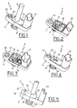
- FIG 1 there is illustrated an end of a rigid tube 1 of a hydraulic circuit, in particular of a vehicle air-conditioning circuit automotive, with a connection and connection 3 connection mounted to one end of the tube 1 and which incorporates a pressure sensor or temperature without the need to drill a hole in the rigid tube 1 to mount the sensor.
- connection and fixing connection 3 consists of by a housing 5 preferably made of a plastic material and whose 2 is illustrated in FIG. 2.
- the housing 5 is pierced by a central orifice 7 which on one side is extended by a connecting end 9 and on the other side, opens into an internal housing or chamber 11 which communicates with the central orifice 7.
- the pressure or temperature sensor 13 is mounted and fixed in the chamber 11 as illustrated in FIG. chamber 11 is sealed by means of a plate 15 forming a cover (FIG. 4) which bears on bosses 17 projecting from bottom of chamber 11 ( Figure 3).
- the plate which can be metallic or made of plastic, is pierced with an orifice 19 axially aligned with the central orifice 7 of the housing 5.
- the plate 15 has a sufficient thickness to provide in its hole 19 a groove 21 adapted to receive a seal O-ring (Figure 4).
- the housing 5 is pierced with a fixing hole 23 (FIGS. 1 to 4) which can receive a metal eyelet of reinforcement 25 (Figures 3 and 4), and towards its other end, a portion forming sheath 27 for the passage of electrical conductors from the sensor 13 to a steering unit (not shown).
- the connection tip 9 of the housing 5 has at least one peripheral groove 29 adapted to receive a seal O-ring ( Figure 4).
- the sensor 13 is mounted in the chamber 11 of the housing 5 ( Figure 3), the chamber 11 is closed by the plate 15 ( Figure 4), and just fix the rigid tube 1 in the orifice 19 of the plate 15, knowing that the free end of the rigid tube 1 can penetrate more or less inside the housing 5 as will be explained later with reference to Figures 6a and 6b.
- Fixing the rigid tube 1 in the orifice 19 of the plate 15 is made of a sealed manner by an operation known per se of fitting, stamping, swaging or rotation-melting for example, sealing possibly obtained by the presence of an O-ring in the groove 19 of the orifice 21 of the plate 15.
- the threaded portion is engaged a bolt for example in the hole 23 of the housing 5 to fix the connection 3 fixing and connecting to one of the elements of the circuit of air conditioner.
- this fixing intervening at a housing 5 plastic material, this material can be caused to flow over time and adversely affect the good behavior of the fixation.
- a metal reinforcement flange 35 is provided. forming a fixing lug which is pierced with a first hole 36 traversed by the end portion of the rigid tube 1 which is fixed to the metal piece 35 by an operation known per se of tip forming such a punching, a dugegeonnage even a brazing for example, and by a second hole of fixing 37 which is axially aligned with the fixing hole 23 of the housing 5 which is pressed against the metal flange 35.
- a nipple of positioning 39 secured to the housing 5 and which enters a blind hole of the metal flange 35.
- the rigid tube 1 with its connectors 3 for fixing and connection is then connected to a socket 40 of the circuit of air conditioning as schematically illustrated in Figures 6a and 6b which are half-axial sections of FIG. 5.
- the female endpiece 40 has a cavity 42 adapted to receive the connection end-piece 9 of the housing 5, the housing 5 bearing on the female end 40.
- the sensor 13 not being mounted in the axis of the central orifice 7 of the housing 5, it provide a bypass of the fluid transported by the rigid tube 1 for bring it to the sensor 13, and the realization of this derivation is function the degree of depression of the rigid tube 1 in the housing 5.
- the rigid tube 1 is introduced into the housing 5 to penetrate into the connection piece 9.
- the bypass of the fluid is ensured by at least one groove 7a machined in the central orifice 7 and which forms a passage adapted to to divert a part of the fluid, at the inlet or at the outlet of the rigid tube 1, towards the chamber 11 to reach the sensor 13.
- the sensor 13 is a pressure sensor, its membrane will be deformed by the pressure of the fluid and the deformations are going to be turned into electrical signals that will be transmitted to the control center.
- the rigid tube 1 is introduced into the housing 5 but without penetrating inside the tip 9, its free end does not protrude from the plate 15 of the housing 5. In this case, the derivation of the fluid is directly ensured by the chamber 11 of the housing 5 in which is housed the sensor 13.
- connection 3 connection and connection is formed of a housing 5 which is fixed directly to one end of the rigid tube 1 but with a sensor 13 positioned otherwise.
- this housing 5 which can be realized also made of plastic material has a tubular body pierced with a central orifice 50 fluid passage.
- the central orifice 50 Towards one end of the part, the central orifice 50 has a enlarged diameter barely greater than the external diameter of the rigid tube 1, and delimits a shoulder 52 forming a stop for the end of the rigid tube 1 engaged in the central orifice 50.
- Fixing the rigid tube 1 in the orifice central 50 can be effected in a sealed manner by means of an adhesive or by a rotation-fusion operation for example.
- the housing 5 forms a connection piece 9 with at least one groove device 29 adapted to receive an O-ring for sealing.
- the housing 5 comprises a housing 58 delimited by at least two radial walls 60 and able to receive the sensor 13 which is communication with the fluid by a radial channel 62 formed in the thickness housing 5 and which communicates with the central orifice 50.
- the housing 5 also includes a boss radially external forming a fastening lug 64 pierced with an orifice 23 for the passage of a screw and or the rod of a bolt for example.
- One eyepiece metal 25 can be mounted in the orifice 66 to ensure better fixing of the connection and fixing connectors 3.
- the tip 9 can be a male endpiece as illustrated above, but can alternatively be a female end when the receiving end of the air conditioning circuit is a male end.
- the tip 9 is able to fit into any element of the air conditioning circuit, the compressor, the condenser, a desiccant tank, expansion system, evaporator or hose, connected by rigid and / or flexible tubes.
- the orifice 19 of the plate 15 may have a profile conformation more elaborate than a simply tubular conformation, in order to be able to fix a tube 1 with pilot bit, flanged, of type snap-on or other that has the complex conformation complementary.
- the invention applies to any circuit and is not limited to a vehicle air conditioning system automobile.
Landscapes
- Engineering & Computer Science (AREA)
- General Engineering & Computer Science (AREA)
- Mechanical Engineering (AREA)
- Measuring Fluid Pressure (AREA)
- Measuring Temperature Or Quantity Of Heat (AREA)
Abstract
Description
- la figure 1 est une vue en perspective pour illustrer l'extrémité d'un tube rigide d'un circuit hydraulique avec sa connectique de fixation et de raccordement selon un premier mode de réalisation de l'invention ;
- les figures 2 à 4 sont des vues en perspective pour illustrer des détails de la connectique de fixation et de raccordement selon le premier mode de réalisation de l'invention ;
- la figure 5 est une vue en perspective d'une variante de réalisation du premier mode de réalisation de la figure 1 ;
- les figures 6a et 6b sont des demi-vues en coupe axiale partielle de la figure 5 pour illustrer deux variantes de réalisation ; et
- la figure 7 est une vue en coupe axiale d'une connectique de fixation et de raccordement selon un second mode de réalisation de l'invention.
Claims (13)
- Procédé de montage d'un capteur (13) dans un circuit hydraulique tel un circuit de climatisation, ledit circuit comprenant au moins un tube rigide (1) avec une connectique (3) de fixation et de raccordement à au moins l'une de ses deux extrémités, caractérisé en ce qu'il consiste à intégrer le capteur (15) dans la connectique (3) de fixation et de raccordement sans percer de trou dans le tube rigide (1) pour y monter le capteur (13), à réaliser la connectique (3) de fixation et de raccordement sous la forme d'un boítier (5) en matière plastique qui, d'un côté, reçoit de manière étanche la partie d'extrémité du tube rigide (1) et, de l'autre côté, se termine par un embout de raccordement (9), à prévoir dans le boítier (5) au moins un passage de dérivation pour amener une partie du fluide véhiculé par le tube rigide (1) vers la chambre (11) dans laquelle est logé le capteur (13), et à prévoir dans le boítier (5) un moyen (23) tel un orifice apte à recevoir un moyen de fixation de la connectique (3) de fixation et de raccordement.
- Procédé de montage selon la revendication 2, dans lequel on ferme la chambre (11) où est logé le capteur (15) par une plaque (15) percée d'un orifice (19) dans lequel la partie d'extrémité du tube rigide (1) est fixée de manière étanche.
- Procédé de montage selon la revendication 1, dans lequel on rapporte sur la partie d'extrémité libre du tube rigide (1) une bride de renfort (35) percé d'un premier trou (36) pour le passage du tube rigide (1) et d'un second trou de fixation (37) axialement aligné avec un trou de fixation (23) percé dans le boítier (5) qui est accolé à la bride de renfort (35).
- Procédé de montage selon la revendication 1, dans lequel on réalise le boítier (5) sous la forme d'un bloc avec un passage central (50) et qui supporte à sa périphérie le capteur (13) avec un passage radial (62) percé dans le boítier (5) pour mettre en communication le capteur (13) avec le passage central (50) où circule le fluide.
- Tube rigide pour circuit hydraulique, en particulier pour circuit de climatisation de véhicule automobile, comprenant une connectique (3) de fixation et de raccordement à l'une de ses extrémités, et qui est équipé d'un capteur (13) de pression ou de température, caractérisé en ce que le capteur (13) est intégré dans la connectique (3) de fixation et de raccordement, et dans lequel la connectique (3) de fixation et de raccordement est constituée par un boítier (5) qui reçoit de manière étanche la partie d'extrémité du tube rigide (1), qui se termine par un embout de raccordement (9), et qui présente au moins un passage de dérivation pour amener une partie du fluide véhiculé par le tube rigide (1) vers un logement ou chambre (11) du boítier (5) dans lequel est logé le capteur (13), et qui présente un moyen (23) tel un orifice apte à recevoir un moyen de fixation de la connectique (3) de fixation et de raccordement.
- Tube rigide selon la revendication 5, dans lequel la chambre (11) est fermée de manière étanche par une plaque (15) qui est percé d'un orifice (19) dans lequel le tube rigide (1) est fixé par une opération d'emmanchement, de matriçage, de dudgeonnage ou de rotation-fusion.
- Tube rigide selon la revendication 6, dans lequel le boítier (5) est également percé d'un orifice (23) pour le passage d'un élément de fixation de la connectique (3) de fixation et de raccordement.
- Tube rigide selon l'une des revendications 5 à 7, dans lequel le boítier (5) est percé d'un orifice central (7) qui débouche dans la chambre (11) où est logé le capteur (13), et dans lequel le passage de dérivation est formé par au moins une rainure (7a) usinée dans l'orifice central (7) au niveau de l'embout de raccordement (9), lorsque l'extrémité libre du tube rigide (1) pénètre au moins en partie dans l'embout de raccordement (9).
- Tube rigide selon la revendication 8, dans lequel le passage de dérivation est formé par la chambre 11 lorsque l'extrémité libre du tube rigide (1) ne pénètre pas dans l'embout de raccordement (9).
- Tube rigide selon la revendication 5, dans lequel le boítier (5) est réalisé en matière plastique, et dans lequel une bride de renfort (35) est fixée autour du tube rigide (1) et contre laquelle vient en appui le boítier (5), ladite bride étant percée d'un orifice de fixation (37) axialement aligné avec l'orifice (23) du boítier (5).
- Tube rigide selon la revendication 5, dans lequel la connectique (3) de fixation et de raccordement est constituée par un boítier (5) sous la forme d'un bloc percé d'un orifice central (50) qui reçoit, d'un côté et d'une manière étanche la partie d'extrémité du tube rigide (1) et qui, de l'autre côté, se termine par un embout de raccordement (9), et dans lequel le boítier (5) supporte extérieurement le capteur (13) qui communique avec l'orifice central (50) par un passage radial (62) ménagé dans le boítier (5).
- Tube rigide selon la revendication 11, dans lequel le boítier (5) comprend également une bride de renfort (64) percée d'un orifice (23) pour le passage d'un élément de fixation.
- Circuit hydraulique, en particulier un circuit de climatisation pour véhicule automobile, comprenant notamment un tube rigide (1) avec à l'une de ses deux extrémités une connectique (3) de fixation et de raccordement, et un capteur (13) de pression ou de température, caractérisé en ce que le capteur (13) est intégré dans la connectique (3) de fixation et de raccordement selon l'une des revendications 5 à 12.
Applications Claiming Priority (2)
| Application Number | Priority Date | Filing Date | Title |
|---|---|---|---|
| FR0406328A FR2871546B1 (fr) | 2004-06-11 | 2004-06-11 | Procede de montage d'un capteur dans un circuit hydraulique, et tube rigide dudit circuit equipe d'un tel capteur |
| FR0406328 | 2004-06-11 |
Publications (2)
| Publication Number | Publication Date |
|---|---|
| EP1605235A1 true EP1605235A1 (fr) | 2005-12-14 |
| EP1605235B1 EP1605235B1 (fr) | 2012-04-25 |
Family
ID=34942378
Family Applications (1)
| Application Number | Title | Priority Date | Filing Date |
|---|---|---|---|
| EP05291197A Expired - Lifetime EP1605235B1 (fr) | 2004-06-11 | 2005-06-03 | Procédé de montage d'un capteur dans un circuit hydraulique, et tube rigide dudit circuit équipé d'un tel capteur |
Country Status (5)
| Country | Link |
|---|---|
| US (1) | US7478561B2 (fr) |
| EP (1) | EP1605235B1 (fr) |
| JP (1) | JP4873890B2 (fr) |
| AT (1) | ATE555368T1 (fr) |
| FR (1) | FR2871546B1 (fr) |
Cited By (2)
| Publication number | Priority date | Publication date | Assignee | Title |
|---|---|---|---|---|
| WO2014096658A1 (fr) * | 2012-12-20 | 2014-06-26 | Valeo Systemes De Controle Moteur | Vanne, notamment vanne de recirculation de gaz d'echappement |
| WO2020070615A1 (fr) * | 2018-10-05 | 2020-04-09 | Payraud Pierre | Dispositif de fixation pour la tenue d'un capteur, comprenant une came |
Families Citing this family (1)
| Publication number | Priority date | Publication date | Assignee | Title |
|---|---|---|---|---|
| US8950191B2 (en) * | 2009-07-02 | 2015-02-10 | Bicent Power Llc | System and method for gas turbine chilled water storage discharge control and/or gas turbine output control |
Citations (4)
| Publication number | Priority date | Publication date | Assignee | Title |
|---|---|---|---|---|
| US3934605A (en) * | 1973-07-03 | 1976-01-27 | Societe Legris France S.A. | Modular distributor box for fluids |
| EP0471121A1 (fr) * | 1990-08-15 | 1992-02-19 | Matsui Manufacturing Co., Ltd. | Dispositif d'identification pour tuyau de transport pneumatique de matériaux pulvérisés ou granulés |
| US5231867A (en) * | 1990-07-05 | 1993-08-03 | Dipl.-Ing. Wrede & Niedecken Verwaltung Gmbh | Device for detecting leaks in a flanged joint |
| EP0585465A1 (fr) * | 1992-02-26 | 1994-03-09 | Daido Co., Ltd. | Construction a double paroi de tube en materiau composite, son procede de production et dispositif a cet effet |
Family Cites Families (2)
| Publication number | Priority date | Publication date | Assignee | Title |
|---|---|---|---|---|
| US3760842A (en) * | 1970-12-29 | 1973-09-25 | T Mikiya | Pressure manifold having plurality of quick connect-disconnect plugs for selectively receiving pressure meter, drain cock, etc. |
| JP2969514B2 (ja) * | 1997-08-27 | 1999-11-02 | 日本ピラー工業株式会社 | 流体計測用センサーの取付構造 |
-
2004
- 2004-06-11 FR FR0406328A patent/FR2871546B1/fr not_active Expired - Fee Related
-
2005
- 2005-06-03 AT AT05291197T patent/ATE555368T1/de active
- 2005-06-03 EP EP05291197A patent/EP1605235B1/fr not_active Expired - Lifetime
- 2005-06-10 US US11/149,319 patent/US7478561B2/en not_active Expired - Fee Related
- 2005-06-10 JP JP2005170947A patent/JP4873890B2/ja not_active Expired - Fee Related
Patent Citations (4)
| Publication number | Priority date | Publication date | Assignee | Title |
|---|---|---|---|---|
| US3934605A (en) * | 1973-07-03 | 1976-01-27 | Societe Legris France S.A. | Modular distributor box for fluids |
| US5231867A (en) * | 1990-07-05 | 1993-08-03 | Dipl.-Ing. Wrede & Niedecken Verwaltung Gmbh | Device for detecting leaks in a flanged joint |
| EP0471121A1 (fr) * | 1990-08-15 | 1992-02-19 | Matsui Manufacturing Co., Ltd. | Dispositif d'identification pour tuyau de transport pneumatique de matériaux pulvérisés ou granulés |
| EP0585465A1 (fr) * | 1992-02-26 | 1994-03-09 | Daido Co., Ltd. | Construction a double paroi de tube en materiau composite, son procede de production et dispositif a cet effet |
Cited By (7)
| Publication number | Priority date | Publication date | Assignee | Title |
|---|---|---|---|---|
| WO2014096658A1 (fr) * | 2012-12-20 | 2014-06-26 | Valeo Systemes De Controle Moteur | Vanne, notamment vanne de recirculation de gaz d'echappement |
| FR3000169A1 (fr) * | 2012-12-20 | 2014-06-27 | Valeo Sys Controle Moteur Sas | Vanne, notamment vanne de recirculation de gaz d'echappement |
| CN104956134A (zh) * | 2012-12-20 | 2015-09-30 | 法雷奥电机控制系统公司 | 阀,特别是排气再循环阀 |
| CN104956134B (zh) * | 2012-12-20 | 2017-03-08 | 法雷奥电机控制系统公司 | 阀 |
| US9951727B2 (en) | 2012-12-20 | 2018-04-24 | Valeo Systemes De Controle Moteur | Valve, particularly an exhaust gas recirculation valve |
| WO2020070615A1 (fr) * | 2018-10-05 | 2020-04-09 | Payraud Pierre | Dispositif de fixation pour la tenue d'un capteur, comprenant une came |
| FR3086878A1 (fr) * | 2018-10-05 | 2020-04-10 | Pierre Payraud | Dispositif de fixation pour la tenue d'un capteur, comprenant une came |
Also Published As
| Publication number | Publication date |
|---|---|
| US20050284230A1 (en) | 2005-12-29 |
| EP1605235B1 (fr) | 2012-04-25 |
| ATE555368T1 (de) | 2012-05-15 |
| FR2871546B1 (fr) | 2008-02-22 |
| JP2006023294A (ja) | 2006-01-26 |
| JP4873890B2 (ja) | 2012-02-08 |
| US7478561B2 (en) | 2009-01-20 |
| FR2871546A1 (fr) | 2005-12-16 |
Similar Documents
| Publication | Publication Date | Title |
|---|---|---|
| EP0840867B1 (fr) | Dispositif de raccordement etanche entre un embout de tube rigide et un tuyau souple et procede de fabrication d'un tel dispositif | |
| EP1605235B1 (fr) | Procédé de montage d'un capteur dans un circuit hydraulique, et tube rigide dudit circuit équipé d'un tel capteur | |
| EP1914464B1 (fr) | Système de détrompage pour le raccordement de canalisations sur un dispositif de commande de fluide | |
| EP1719945B1 (fr) | Connectique de raccordement d'un tube d'un flexible à haute pression pour un circuit de climatisation par exemple | |
| FR2924193A1 (fr) | Raccord etanche et procede de montage d'un tel reccord | |
| EP1568469B1 (fr) | Procédé de piquage d'un corps tubulaire sur un conduit de transfert de fluide, et conduit ainsi piqué | |
| FR2769961A1 (fr) | Cylindre recepteur equipe d'un adaptateur en matiere plastique | |
| EP1498672A1 (fr) | Elément tubulaire pour circuit de climatisation | |
| WO2002008677A1 (fr) | Dispositif detendeur pour fluide frigorigene et circuit de conditionnement comprenant un tel dispositif | |
| EP1801486A1 (fr) | Atténuateur de bruit pour flexible hydraulique, flexible qui en est porvu et système de direction assistée l'incorporant | |
| FR2818730A1 (fr) | Embout femelle pour coupleur | |
| FR3052528A1 (fr) | Vanne anti-retour et circuit et dispositif de refroidissement pour un vehicule comportant une telle vanne | |
| WO2020193437A1 (fr) | Réservoir pour gaz sous pression | |
| FR2903756A1 (fr) | Attenuateur de bruit pour conduite de fluide hydraulique, article comprenant cet attenuateur, conduite compreant cet article et procede d'assemblage. | |
| EP1719940A1 (fr) | Flexible, en particulier pour circuit de climatisation, équipé d'un système de raccordement étanche entre un élément tubulaire rigide et un élément tubulaire souple du flexible | |
| EP1619437A1 (fr) | Raccord de piquage | |
| WO2008096067A2 (fr) | Dispositif de protection d'organes de direction et/ou de transmission et soufflet de protection équipant un tel dispositif | |
| FR2936477A1 (fr) | Raccord permettant le montage d'un capteur et amplificateur de freinage comportant un tel raccord | |
| FR2707891A1 (fr) | Dispositif de filtration pour circuit frigorifique et procédé de fabrication d'un tel dispositif. | |
| EP1821023B1 (fr) | Dispositif réducteur de bruit pour circuit de climatisation de véhicule automobile, et un tel circuit | |
| FR2847021A1 (fr) | Raccord de piece sur tube de dimension sensiblement inferieur, embout et piece pour un tel raccord | |
| EP2141401A1 (fr) | Raccord pour le branchement de tuyaux notamment d'un circuit de depression du moteur d'un véhicule automobile | |
| FR2941205A1 (fr) | Amplificateur de la force de freinage comprenant un raccord pneumatique pour un vehicule, procede d'assemblage d'un tel amplificateur de la force de freinage, et vehicule comprenant un tel amplificateur de la force de freinage. | |
| WO1998058204A1 (fr) | Dispositif de raccordement etanche entre un embout de tube metallique et l'extremite d'un tuyau souple, et procede de fabrication d'un tel dispositif | |
| FR2910108A1 (fr) | Raccord pour raccorder un tuyau de chauffage a un accessoire de raccordement d'une installation de chauffage et/ou climatisation. |
Legal Events
| Date | Code | Title | Description |
|---|---|---|---|
| PUAI | Public reference made under article 153(3) epc to a published international application that has entered the european phase |
Free format text: ORIGINAL CODE: 0009012 |
|
| AK | Designated contracting states |
Kind code of ref document: A1 Designated state(s): AT BE BG CH CY CZ DE DK EE ES FI FR GB GR HU IE IS IT LI LT LU MC NL PL PT RO SE SI SK TR |
|
| AX | Request for extension of the european patent |
Extension state: AL BA HR LV MK YU |
|
| 17P | Request for examination filed |
Effective date: 20060607 |
|
| AKX | Designation fees paid |
Designated state(s): AT BE BG CH CY CZ DE DK EE ES FI FR GB GR HU IE IS IT LI LT LU MC NL PL PT RO SE SI SK TR |
|
| 17Q | First examination report despatched |
Effective date: 20070618 |
|
| GRAP | Despatch of communication of intention to grant a patent |
Free format text: ORIGINAL CODE: EPIDOSNIGR1 |
|
| GRAS | Grant fee paid |
Free format text: ORIGINAL CODE: EPIDOSNIGR3 |
|
| GRAA | (expected) grant |
Free format text: ORIGINAL CODE: 0009210 |
|
| AK | Designated contracting states |
Kind code of ref document: B1 Designated state(s): AT BE BG CH CY CZ DE DK EE ES FI FR GB GR HU IE IS IT LI LT LU MC NL PL PT RO SE SI SK TR |
|
| REG | Reference to a national code |
Ref country code: GB Ref legal event code: FG4D Free format text: NOT ENGLISH |
|
| REG | Reference to a national code |
Ref country code: CH Ref legal event code: EP |
|
| REG | Reference to a national code |
Ref country code: AT Ref legal event code: REF Ref document number: 555368 Country of ref document: AT Kind code of ref document: T Effective date: 20120515 |
|
| REG | Reference to a national code |
Ref country code: IE Ref legal event code: FG4D Free format text: LANGUAGE OF EP DOCUMENT: FRENCH |
|
| REG | Reference to a national code |
Ref country code: DE Ref legal event code: R096 Ref document number: 602005033833 Country of ref document: DE Effective date: 20120621 |
|
| REG | Reference to a national code |
Ref country code: NL Ref legal event code: VDEP Effective date: 20120425 |
|
| REG | Reference to a national code |
Ref country code: AT Ref legal event code: MK05 Ref document number: 555368 Country of ref document: AT Kind code of ref document: T Effective date: 20120425 |
|
| LTIE | Lt: invalidation of european patent or patent extension |
Effective date: 20120425 |
|
| PG25 | Lapsed in a contracting state [announced via postgrant information from national office to epo] |
Ref country code: PL Free format text: LAPSE BECAUSE OF FAILURE TO SUBMIT A TRANSLATION OF THE DESCRIPTION OR TO PAY THE FEE WITHIN THE PRESCRIBED TIME-LIMIT Effective date: 20120425 Ref country code: IS Free format text: LAPSE BECAUSE OF FAILURE TO SUBMIT A TRANSLATION OF THE DESCRIPTION OR TO PAY THE FEE WITHIN THE PRESCRIBED TIME-LIMIT Effective date: 20120825 Ref country code: LT Free format text: LAPSE BECAUSE OF FAILURE TO SUBMIT A TRANSLATION OF THE DESCRIPTION OR TO PAY THE FEE WITHIN THE PRESCRIBED TIME-LIMIT Effective date: 20120425 Ref country code: SE Free format text: LAPSE BECAUSE OF FAILURE TO SUBMIT A TRANSLATION OF THE DESCRIPTION OR TO PAY THE FEE WITHIN THE PRESCRIBED TIME-LIMIT Effective date: 20120425 Ref country code: CY Free format text: LAPSE BECAUSE OF FAILURE TO SUBMIT A TRANSLATION OF THE DESCRIPTION OR TO PAY THE FEE WITHIN THE PRESCRIBED TIME-LIMIT Effective date: 20120425 Ref country code: FI Free format text: LAPSE BECAUSE OF FAILURE TO SUBMIT A TRANSLATION OF THE DESCRIPTION OR TO PAY THE FEE WITHIN THE PRESCRIBED TIME-LIMIT Effective date: 20120425 |
|
| PG25 | Lapsed in a contracting state [announced via postgrant information from national office to epo] |
Ref country code: SI Free format text: LAPSE BECAUSE OF FAILURE TO SUBMIT A TRANSLATION OF THE DESCRIPTION OR TO PAY THE FEE WITHIN THE PRESCRIBED TIME-LIMIT Effective date: 20120425 Ref country code: GR Free format text: LAPSE BECAUSE OF FAILURE TO SUBMIT A TRANSLATION OF THE DESCRIPTION OR TO PAY THE FEE WITHIN THE PRESCRIBED TIME-LIMIT Effective date: 20120726 Ref country code: PT Free format text: LAPSE BECAUSE OF FAILURE TO SUBMIT A TRANSLATION OF THE DESCRIPTION OR TO PAY THE FEE WITHIN THE PRESCRIBED TIME-LIMIT Effective date: 20120827 |
|
| BERE | Be: lapsed |
Owner name: HUTCHINSON Effective date: 20120630 |
|
| PG25 | Lapsed in a contracting state [announced via postgrant information from national office to epo] |
Ref country code: CZ Free format text: LAPSE BECAUSE OF FAILURE TO SUBMIT A TRANSLATION OF THE DESCRIPTION OR TO PAY THE FEE WITHIN THE PRESCRIBED TIME-LIMIT Effective date: 20120425 Ref country code: NL Free format text: LAPSE BECAUSE OF FAILURE TO SUBMIT A TRANSLATION OF THE DESCRIPTION OR TO PAY THE FEE WITHIN THE PRESCRIBED TIME-LIMIT Effective date: 20120425 Ref country code: RO Free format text: LAPSE BECAUSE OF FAILURE TO SUBMIT A TRANSLATION OF THE DESCRIPTION OR TO PAY THE FEE WITHIN THE PRESCRIBED TIME-LIMIT Effective date: 20120425 Ref country code: DK Free format text: LAPSE BECAUSE OF FAILURE TO SUBMIT A TRANSLATION OF THE DESCRIPTION OR TO PAY THE FEE WITHIN THE PRESCRIBED TIME-LIMIT Effective date: 20120425 Ref country code: AT Free format text: LAPSE BECAUSE OF FAILURE TO SUBMIT A TRANSLATION OF THE DESCRIPTION OR TO PAY THE FEE WITHIN THE PRESCRIBED TIME-LIMIT Effective date: 20120425 Ref country code: SK Free format text: LAPSE BECAUSE OF FAILURE TO SUBMIT A TRANSLATION OF THE DESCRIPTION OR TO PAY THE FEE WITHIN THE PRESCRIBED TIME-LIMIT Effective date: 20120425 Ref country code: MC Free format text: LAPSE BECAUSE OF NON-PAYMENT OF DUE FEES Effective date: 20120630 Ref country code: EE Free format text: LAPSE BECAUSE OF FAILURE TO SUBMIT A TRANSLATION OF THE DESCRIPTION OR TO PAY THE FEE WITHIN THE PRESCRIBED TIME-LIMIT Effective date: 20120425 |
|
| REG | Reference to a national code |
Ref country code: CH Ref legal event code: PL |
|
| REG | Reference to a national code |
Ref country code: CH Ref legal event code: PL |
|
| PG25 | Lapsed in a contracting state [announced via postgrant information from national office to epo] |
Ref country code: IT Free format text: LAPSE BECAUSE OF FAILURE TO SUBMIT A TRANSLATION OF THE DESCRIPTION OR TO PAY THE FEE WITHIN THE PRESCRIBED TIME-LIMIT Effective date: 20120425 |
|
| PLBE | No opposition filed within time limit |
Free format text: ORIGINAL CODE: 0009261 |
|
| STAA | Information on the status of an ep patent application or granted ep patent |
Free format text: STATUS: NO OPPOSITION FILED WITHIN TIME LIMIT |
|
| GBPC | Gb: european patent ceased through non-payment of renewal fee |
Effective date: 20120725 |
|
| REG | Reference to a national code |
Ref country code: IE Ref legal event code: MM4A |
|
| 26N | No opposition filed |
Effective date: 20130128 |
|
| PG25 | Lapsed in a contracting state [announced via postgrant information from national office to epo] |
Ref country code: ES Free format text: LAPSE BECAUSE OF FAILURE TO SUBMIT A TRANSLATION OF THE DESCRIPTION OR TO PAY THE FEE WITHIN THE PRESCRIBED TIME-LIMIT Effective date: 20120805 Ref country code: GB Free format text: LAPSE BECAUSE OF NON-PAYMENT OF DUE FEES Effective date: 20120725 Ref country code: BE Free format text: LAPSE BECAUSE OF NON-PAYMENT OF DUE FEES Effective date: 20120630 Ref country code: CH Free format text: LAPSE BECAUSE OF NON-PAYMENT OF DUE FEES Effective date: 20120630 Ref country code: IE Free format text: LAPSE BECAUSE OF NON-PAYMENT OF DUE FEES Effective date: 20120603 Ref country code: LI Free format text: LAPSE BECAUSE OF NON-PAYMENT OF DUE FEES Effective date: 20120630 |
|
| REG | Reference to a national code |
Ref country code: DE Ref legal event code: R097 Ref document number: 602005033833 Country of ref document: DE Effective date: 20130128 |
|
| PG25 | Lapsed in a contracting state [announced via postgrant information from national office to epo] |
Ref country code: BG Free format text: LAPSE BECAUSE OF FAILURE TO SUBMIT A TRANSLATION OF THE DESCRIPTION OR TO PAY THE FEE WITHIN THE PRESCRIBED TIME-LIMIT Effective date: 20120725 |
|
| PG25 | Lapsed in a contracting state [announced via postgrant information from national office to epo] |
Ref country code: TR Free format text: LAPSE BECAUSE OF FAILURE TO SUBMIT A TRANSLATION OF THE DESCRIPTION OR TO PAY THE FEE WITHIN THE PRESCRIBED TIME-LIMIT Effective date: 20120425 |
|
| PG25 | Lapsed in a contracting state [announced via postgrant information from national office to epo] |
Ref country code: LU Free format text: LAPSE BECAUSE OF NON-PAYMENT OF DUE FEES Effective date: 20120603 |
|
| PG25 | Lapsed in a contracting state [announced via postgrant information from national office to epo] |
Ref country code: HU Free format text: LAPSE BECAUSE OF FAILURE TO SUBMIT A TRANSLATION OF THE DESCRIPTION OR TO PAY THE FEE WITHIN THE PRESCRIBED TIME-LIMIT Effective date: 20050603 |
|
| REG | Reference to a national code |
Ref country code: FR Ref legal event code: PLFP Year of fee payment: 11 |
|
| REG | Reference to a national code |
Ref country code: FR Ref legal event code: PLFP Year of fee payment: 12 |
|
| REG | Reference to a national code |
Ref country code: FR Ref legal event code: PLFP Year of fee payment: 13 |
|
| REG | Reference to a national code |
Ref country code: FR Ref legal event code: PLFP Year of fee payment: 14 |
|
| PGFP | Annual fee paid to national office [announced via postgrant information from national office to epo] |
Ref country code: DE Payment date: 20180625 Year of fee payment: 14 |
|
| PGFP | Annual fee paid to national office [announced via postgrant information from national office to epo] |
Ref country code: FR Payment date: 20180523 Year of fee payment: 14 |
|
| REG | Reference to a national code |
Ref country code: DE Ref legal event code: R119 Ref document number: 602005033833 Country of ref document: DE |
|
| PG25 | Lapsed in a contracting state [announced via postgrant information from national office to epo] |
Ref country code: DE Free format text: LAPSE BECAUSE OF NON-PAYMENT OF DUE FEES Effective date: 20200101 |
|
| PG25 | Lapsed in a contracting state [announced via postgrant information from national office to epo] |
Ref country code: FR Free format text: LAPSE BECAUSE OF NON-PAYMENT OF DUE FEES Effective date: 20190630 |