EP1604608A1 - Retinaschutzvorrichtung für ein Operationsmikroskop - Google Patents
Retinaschutzvorrichtung für ein Operationsmikroskop Download PDFInfo
- Publication number
- EP1604608A1 EP1604608A1 EP05104981A EP05104981A EP1604608A1 EP 1604608 A1 EP1604608 A1 EP 1604608A1 EP 05104981 A EP05104981 A EP 05104981A EP 05104981 A EP05104981 A EP 05104981A EP 1604608 A1 EP1604608 A1 EP 1604608A1
- Authority
- EP
- European Patent Office
- Prior art keywords
- optical element
- eye
- beam path
- illumination beam
- protection device
- Prior art date
- Legal status (The legal status is an assumption and is not a legal conclusion. Google has not performed a legal analysis and makes no representation as to the accuracy of the status listed.)
- Withdrawn
Links
- 210000001525 retina Anatomy 0.000 title claims abstract description 29
- 230000003287 optical effect Effects 0.000 claims description 32
- 238000005286 illumination Methods 0.000 claims description 28
- 230000001681 protective effect Effects 0.000 claims description 13
- 210000001747 pupil Anatomy 0.000 description 8
- 230000000694 effects Effects 0.000 description 3
- 210000004087 cornea Anatomy 0.000 description 2
- 238000010521 absorption reaction Methods 0.000 description 1
- 239000012876 carrier material Substances 0.000 description 1
- 230000001609 comparable effect Effects 0.000 description 1
- 230000001419 dependent effect Effects 0.000 description 1
- 230000031700 light absorption Effects 0.000 description 1
- 230000002093 peripheral effect Effects 0.000 description 1
- 230000002207 retinal effect Effects 0.000 description 1
- 230000003595 spectral effect Effects 0.000 description 1
- 238000001356 surgical procedure Methods 0.000 description 1
- 238000012876 topography Methods 0.000 description 1
Images


Classifications
-
- A—HUMAN NECESSITIES
- A61—MEDICAL OR VETERINARY SCIENCE; HYGIENE
- A61B—DIAGNOSIS; SURGERY; IDENTIFICATION
- A61B3/00—Apparatus for testing the eyes; Instruments for examining the eyes
- A61B3/10—Objective types, i.e. instruments for examining the eyes independent of the patients' perceptions or reactions
- A61B3/13—Ophthalmic microscopes
-
- A—HUMAN NECESSITIES
- A61—MEDICAL OR VETERINARY SCIENCE; HYGIENE
- A61B—DIAGNOSIS; SURGERY; IDENTIFICATION
- A61B3/00—Apparatus for testing the eyes; Instruments for examining the eyes
- A61B3/10—Objective types, i.e. instruments for examining the eyes independent of the patients' perceptions or reactions
- A61B3/14—Arrangements specially adapted for eye photography
- A61B3/15—Arrangements specially adapted for eye photography with means for aligning, spacing or blocking spurious reflection ; with means for relaxing
- A61B3/156—Arrangements specially adapted for eye photography with means for aligning, spacing or blocking spurious reflection ; with means for relaxing for blocking
-
- G—PHYSICS
- G02—OPTICS
- G02B—OPTICAL ELEMENTS, SYSTEMS OR APPARATUS
- G02B21/00—Microscopes
- G02B21/0004—Microscopes specially adapted for specific applications
- G02B21/0012—Surgical microscopes
-
- G—PHYSICS
- G02—OPTICS
- G02B—OPTICAL ELEMENTS, SYSTEMS OR APPARATUS
- G02B21/00—Microscopes
- G02B21/06—Means for illuminating specimens
- G02B21/08—Condensers
- G02B21/082—Condensers for incident illumination only
- G02B21/084—Condensers for incident illumination only having annular illumination around the objective
-
- A—HUMAN NECESSITIES
- A61—MEDICAL OR VETERINARY SCIENCE; HYGIENE
- A61F—FILTERS IMPLANTABLE INTO BLOOD VESSELS; PROSTHESES; DEVICES PROVIDING PATENCY TO, OR PREVENTING COLLAPSING OF, TUBULAR STRUCTURES OF THE BODY, e.g. STENTS; ORTHOPAEDIC, NURSING OR CONTRACEPTIVE DEVICES; FOMENTATION; TREATMENT OR PROTECTION OF EYES OR EARS; BANDAGES, DRESSINGS OR ABSORBENT PADS; FIRST-AID KITS
- A61F9/00—Methods or devices for treatment of the eyes; Devices for putting in contact-lenses; Devices to correct squinting; Apparatus to guide the blind; Protective devices for the eyes, carried on the body or in the hand
- A61F9/007—Methods or devices for eye surgery
Definitions
- the invention relates to an eye, in particular retina protection device and an optical element having a freeform surface for a lighting beam path, as well as the use of a optical element with freeform surface to protect the retina of the Patient's eye during eye surgery.
- the patient's eye should be temporarily protected from the light that a surgeon Illumination of the surgical field on the eye is used.
- the retina as well as the Cornea and the lens could otherwise be too large Irradiation dose to be damaged.
- filters are used filter out harmful spectral components of the light.
- DE-A1-33 39 172 describes a light trap for Surgical microscopes. With one in the illumination beam path a surgical microscope swiveling aperture become zones of the light field shadowed in the object field. When shadowing the Midfield of light in the area of the pupil will prevent a harmful light beam falls on the retina of the patient's eye. It forms so a dark spot centric in the light field above the Patient pupil off.
- the eye in particular retina protection device according to the invention for a surgical microscope consists of an illumination beam path, which defines a light field for an object plane, and an optical element in the illumination beam path, which is such is designed that it emits light from the central area of the Light field deflects.
- an optical element in the illumination beam path which is such is designed that it emits light from the central area of the Light field deflects.
- the Eye is rolled and the pupil is not in the central area, the light becomes decentralized from one of these positions Area of the light field out.
- the light is not in the center or in the decentralized area in heat converted, but led away from there.
- Such an optical element may be in its peripheral area partially have an infinite radius, so here is the Distraction effect is eliminated.
- the surface of the formed by a free-form surface optical element can also be non-rotationally symmetric deviations from the sphere, preferably a topography, e.g. is represented by a polynomial of higher order.
- the optical Element can optionally from the illumination beam path electrically or electronically controlled - optionally remotely controlled - be swung in by motor.
- the eye in particular retina protection device according to the invention does not have to be used exclusively for a surgical microscope rather, it can also be used in other optical devices be installed.
- Fig. 1 shows a representation of an illumination beam path of a Microscope 17 in application of a retinal protective shield 13 after the State of the art.
- a light source 1 From a light source 1 is light in the Illuminating beam emitted, which also condenser lenses 2a and 2b of the illumination beam path has.
- a field diaphragm 3 In one to the object level conjugate level is a field diaphragm 3 and in the same level a retina protective shield 13, which is the light in the absorbed central area of the illumination beam path.
- Deflection elements 5 and 6 and an optic 7 passes the remaining Light on the surgical field.
- the shading 8, caused by the retina protective shield 13, the pupil in the iris 10 covers one Patient's eye.
- the light passes through partial regions of the cornea 9 possibly on the iris 10, but not on the pupil or on the lens 11 of the patient's eye and thus not on the retina this eye.
- the observer eye 16 is a Surgeons presented.
- Fig. 2 is an illustration of the illumination beam path of a Microscope 17 in application of an optical according to the invention Elements 4, in particular a special retina protective lens with Freeform surface.
- Elements 4 Located in the plane conjugate to the object plane 14 the optical element 4, in particular the retina protective lens, which the light from the central area of the illumination beam path deflects and does not absorb. The light amplifies either the light intensity in the remaining area or is in for the retina unproblematic other lateral areas of the Illuminated beam path.
- the shading 8, by the Free-form surface of the retina protective lens is produced, causes the effect as explained in the description of FIG. 1.
- FIG. 3 is an illustration of the illumination beam path of a Microscope 17 in application of an optical according to the invention Elements, in particular a condenser lens 2c with free-form surface. Outside the level conjugated to the object plane 14 is located a condenser lens 2c with free-form surface, which the light from the deflects the central area of the illumination beam path.
- the Shading 8, through the free-form surface of the condenser lens 2c is produced causes the effect as in the description of FIG. 1 explained.
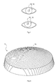
- Fig. 4 shows a representation of the eye of a patient in two different pupil positions.
- the iris 10 In the upper part is the iris 10 with the Pupil 18 centrally aligned and in the lower part to the left above rolled, so decentralized.
- Fig. 5 is an enlarged view of an inventive optical element 4, in particular a retina protective lens.
- the Free-form surface 15 illustrated by way of example is designed such that it deflects the light from the central illuminated area.
Landscapes
- Health & Medical Sciences (AREA)
- Life Sciences & Earth Sciences (AREA)
- Physics & Mathematics (AREA)
- Surgery (AREA)
- General Health & Medical Sciences (AREA)
- Ophthalmology & Optometry (AREA)
- Biomedical Technology (AREA)
- General Physics & Mathematics (AREA)
- Analytical Chemistry (AREA)
- Biophysics (AREA)
- Chemical & Material Sciences (AREA)
- Engineering & Computer Science (AREA)
- Optics & Photonics (AREA)
- Heart & Thoracic Surgery (AREA)
- Medical Informatics (AREA)
- Molecular Biology (AREA)
- Animal Behavior & Ethology (AREA)
- Public Health (AREA)
- Veterinary Medicine (AREA)
- Microscoopes, Condenser (AREA)
- Prostheses (AREA)
Abstract
Description
- Fig. 1 -
- eine schematische Darstellung eines Beleuchtungsstrahlenganges in Anwendung einer Retina-Schutzblende nach dem Stand der Technik,
- Fig. 2 -
- eine schematische Darstellung eines Beleuchtungsstrahlenganges in Anwendung eines erfindungsgemäßen optischen Elements, insbesondere einer speziellen Retina-Schutzlinse mit Freiformfläche,
- Fig. 3 -
- eine schematische Darstellung eines Beleuchtungsstrahlenganges in Anwendung eines erfindungsgemäßen optischen Elements, insbesondere einer Kondensorlinse mit Freiformfläche,
- Fig. 4 -
- ine schematische Darstellung des Auges eines Patienten in zwei verschiedenen Pupillenpositionen und
- Fig. 5 -
- eine schematische Darstellung eines erfindungsgemäßen optischen Elements, insbesondere einer Retina-Schutzlinse mit Freiformfläche.
Claims (12)
- Augen-, insbesondere Retina-Schutzvorrichtung für ein Operationsmikroskop mit einem Beleuchtungsstrahlengang, der ein Leuchtfeld für eine Objektebene (14) definiert, und einem optischen Element (4) im Beleuchtungsstrahlengang, dadurch gekennzeichnet, dass das optische Element (4) derart ausgebildet ist, dass es Licht aus dem zentralen oder einem dezentralen Bereich des Leuchtfeldes herauslenkt.
- Augen-, insbesondere Retina-Schutzvorrichtung nach Anspruch 1, dadurch gekennzeichnet, dass das optische Element aus einer optischen Linse (4) besteht.
- Augen-, insbesondere Retina-Schutzvorrichtung nach einem der vorhergehenden Ansprüche, dadurch gekennzeichnet, dass die brechenden Flächen der Linse (4) seitlich des zentralen oder dezentralen Bereichs einen unendlichen Radius aufweisen.
- Augen-, insbesondere Retina-Schutzvorrichtung nach einem der vorhergehenden Ansprüche, dadurch gekennzeichnet, dass das optische Element (4) wenigstens eine Freiformfläche (15) aufweist.
- Augen-, insbesondere Retina-Schutzvorrichtung nach einem der vorhergehenden Ansprüche, dadurch gekennzeichnet, dass die Linse (4) im zentralen oder in einem dezentralen Bereich des Beleuchtungsstrahlenganges in einer zur Objektebene (14) konjugierten Ebene angeordnet ist.
- Augen-, insbesondere Retina-Schutzvorrichtung nach einem der vorhergehenden Ansprüche, dadurch gekennzeichnet, dass das optische Element wenigstens eine Kondensorlinse (2c) außerhalb einer zur Objektebene (14) konjugierten Ebene umfasst, an der wenigstens eine Freiformfläche (15) ausgestaltet ist.
- Augen-, insbesondere Retina-Schutzvorrichtung nach einem der vorhergehenden Ansprüche, dadurch gekennzeichnet, dass das optische Element (4) aus dem Beleuchtungsstrahlengang - gegebenenfalls ferngesteuert - entfernbar ist.
- Augen-, insbesondere Retina-Schutzvorrichtung nach einem der vorhergehenden Ansprüche, dadurch gekennzeichnet, dass das optische Element (4) aus dem Beleuchtungsstrahlengang elektrisch oder elektronisch angesteuert motorisch entfernbar ist.
- Optisches Element (4) mit einer Freiformfläche für einen Beleuchtungsstrahlengang, der ein Leuchtfeld definiert, dadurch gekennzeichnet, dass das optische Element (4) so ausgebildet ist, dass es im Anwendungsfall Licht aus dem zentralen oder einem dezentralen Bereich eines Leuchtfeldes heraus in den verbleibenden Bereich desselben Leuchtfeldes hineinlenkt.
- Optisches Element (4) nach Anspruch 9, dadurch gekennzeichnet, dass es im zentralen oder dezentralen Bereich des Beleuchtungsstrahlenganges eines Operationsmikroskops in einer zur Objektebene (14) konjugierten Ebene angeordnet ist.
- Optisches Element (4) nach einem der Ansprüche 9 oder 10, dadurch gekennzeichnet, dass es aus dem Beleuchtungsstrahlengang - vorzugsweise motorisch gesteuert - entfernbar ist.
- Verwendung eines optischen Elements mit Freiformfläche (15) als Augenschutzvorrichtung, vorzugsweise in einem optischen Vergrößerungsgerät.
Applications Claiming Priority (2)
| Application Number | Priority Date | Filing Date | Title |
|---|---|---|---|
| DE102004028470 | 2004-06-11 | ||
| DE102004028470A DE102004028470A1 (de) | 2004-06-11 | 2004-06-11 | Augen-, insbesondere Retinaschutzvorrichtung und optisches Element mit einer Freiformfläche für einen Beleuchtungsstrahlengang, sowie Verwendung eines optischen Elements mit Freiformfläche |
Publications (1)
| Publication Number | Publication Date |
|---|---|
| EP1604608A1 true EP1604608A1 (de) | 2005-12-14 |
Family
ID=34940107
Family Applications (1)
| Application Number | Title | Priority Date | Filing Date |
|---|---|---|---|
| EP05104981A Withdrawn EP1604608A1 (de) | 2004-06-11 | 2005-06-08 | Retinaschutzvorrichtung für ein Operationsmikroskop |
Country Status (4)
| Country | Link |
|---|---|
| US (1) | US7434934B2 (de) |
| EP (1) | EP1604608A1 (de) |
| JP (1) | JP4974481B2 (de) |
| DE (1) | DE102004028470A1 (de) |
Cited By (1)
| Publication number | Priority date | Publication date | Assignee | Title |
|---|---|---|---|---|
| EP1632171A3 (de) * | 2004-06-11 | 2008-02-13 | Leica Microsystems (Schweiz) AG | Beleuchtungsvorrichtung, insbesondere Spaltlampe |
Families Citing this family (3)
| Publication number | Priority date | Publication date | Assignee | Title |
|---|---|---|---|---|
| ES2289957B1 (es) | 2007-02-07 | 2008-12-01 | Universidad Complutense De Madrid | Fuente de iluminacion con emision reducida de longitudes de onda corta para la proteccion de ojos. |
| DE102007023445A1 (de) * | 2007-05-16 | 2008-11-20 | Jenoptik Laser, Optik, Systeme Gmbh | Konfokal bildgebendes optisches System und Messanordnung zur Mittendickenmessung |
| DE102011088039B4 (de) * | 2011-12-08 | 2020-01-16 | Leica Microsystems (Schweiz) Ag | Operationsmikroskopsystem für die Ophthalmologie und zugehörige Detektionseinheit |
Citations (3)
| Publication number | Priority date | Publication date | Assignee | Title |
|---|---|---|---|---|
| DE3339172A1 (de) * | 1983-10-28 | 1985-05-15 | Fa. Carl Zeiss, 7920 Heidenheim | Lichtfalle fuer augenuntersuchungsgeraete |
| EP0611547A1 (de) * | 1993-02-03 | 1994-08-24 | J.D. Möller Optische Werke GmbH | Operationsmikroskop |
| DE10207379A1 (de) * | 2002-02-21 | 2003-09-04 | Asphericon Gmbh | Verfahren zum Schleifen und Polieren von Freiformflächen, insbesondere von rotationssymmetrischen asphärischen optischen Linsen |
Family Cites Families (11)
| Publication number | Priority date | Publication date | Assignee | Title |
|---|---|---|---|---|
| JPS6264334A (ja) * | 1985-09-12 | 1987-03-23 | キヤノン株式会社 | 眼科用照明装置 |
| JPS62101242A (ja) * | 1985-10-29 | 1987-05-11 | オリンパス光学工業株式会社 | 手術用顕微鏡 |
| JPH01255817A (ja) * | 1988-04-06 | 1989-10-12 | Canon Inc | 顕微鏡用照明装置 |
| JP3631302B2 (ja) * | 1995-10-11 | 2005-03-23 | オリンパス株式会社 | 実体顕微鏡 |
| US6483638B1 (en) * | 1996-07-22 | 2002-11-19 | Kla-Tencor Corporation | Ultra-broadband UV microscope imaging system with wide range zoom capability |
| DE19638263B4 (de) * | 1996-09-19 | 2004-01-29 | Carl Zeiss | Ophthalmologisches Beobachtungsgerät |
| US6160668A (en) * | 1998-05-14 | 2000-12-12 | Pilkington Pe Limited | Optical systems |
| KR20040015251A (ko) * | 2001-05-15 | 2004-02-18 | 칼 짜이스 에스엠티 아게 | 불화물 결정 렌즈들을 포함하는 렌즈 시스템 |
| JP4068371B2 (ja) * | 2001-06-13 | 2008-03-26 | 株式会社トプコン | 手術用顕微鏡 |
| US6636366B1 (en) * | 2001-09-21 | 2003-10-21 | Victor Company Of Japan, Limited | Objective for optical disk, optical pickup, optical disk writer-reader, and optical disk reader |
| JP4340656B2 (ja) * | 2003-06-30 | 2009-10-07 | 株式会社ライト製作所 | 眼屈折力測定装置 |
-
2004
- 2004-06-11 DE DE102004028470A patent/DE102004028470A1/de not_active Withdrawn
-
2005
- 2005-06-08 EP EP05104981A patent/EP1604608A1/de not_active Withdrawn
- 2005-06-09 US US11/148,765 patent/US7434934B2/en not_active Expired - Fee Related
- 2005-06-13 JP JP2005172085A patent/JP4974481B2/ja not_active Expired - Fee Related
Patent Citations (3)
| Publication number | Priority date | Publication date | Assignee | Title |
|---|---|---|---|---|
| DE3339172A1 (de) * | 1983-10-28 | 1985-05-15 | Fa. Carl Zeiss, 7920 Heidenheim | Lichtfalle fuer augenuntersuchungsgeraete |
| EP0611547A1 (de) * | 1993-02-03 | 1994-08-24 | J.D. Möller Optische Werke GmbH | Operationsmikroskop |
| DE10207379A1 (de) * | 2002-02-21 | 2003-09-04 | Asphericon Gmbh | Verfahren zum Schleifen und Polieren von Freiformflächen, insbesondere von rotationssymmetrischen asphärischen optischen Linsen |
Non-Patent Citations (2)
| Title |
|---|
| CARL ZEISS, OBERKOCHEN: "Innovation 11, the Magazine from Carl Zeiss No. 11", June 2002 (2002-06-01), Retrieved from the Internet <URL:http://www.zeiss.de/C125716F004E0776/0/89B5E684C76DE80CC125716F005491F5/$File/innovation_11.pdf> [retrieved on 20110715] * |
| RIES H.; MUSCHAWECK J.: "Tailored freeform optical surfaces", J. OPT. SOC. AM. A, vol. 19, no. 3, March 2002 (2002-03-01), USA, pages 590 - 595 * |
Cited By (1)
| Publication number | Priority date | Publication date | Assignee | Title |
|---|---|---|---|---|
| EP1632171A3 (de) * | 2004-06-11 | 2008-02-13 | Leica Microsystems (Schweiz) AG | Beleuchtungsvorrichtung, insbesondere Spaltlampe |
Also Published As
| Publication number | Publication date |
|---|---|
| US7434934B2 (en) | 2008-10-14 |
| DE102004028470A1 (de) | 2005-12-29 |
| US20050283142A1 (en) | 2005-12-22 |
| JP2005349211A (ja) | 2005-12-22 |
| JP4974481B2 (ja) | 2012-07-11 |
Similar Documents
| Publication | Publication Date | Title |
|---|---|---|
| DE19746483C5 (de) | Vorrichtung zur Formgebung von optischen Linsen durch Materialabtrag | |
| EP2452616B1 (de) | Beobachtungseinrichtung | |
| DE9017860U1 (de) | Beleuchtungseinrichtung für ein Operationsmikroskop | |
| DE69936214T2 (de) | Chirurgisches Augenfixationsgerät | |
| DE19638263B4 (de) | Ophthalmologisches Beobachtungsgerät | |
| EP1291696B1 (de) | Prismenkonstruktion für simultane 0-Grad und Schräg-Beleuchtung eines Stereo-Operationsmikroskops | |
| EP3156828B1 (de) | Operationsmikroskop | |
| EP1997423B1 (de) | Operationsmikroskop mit Beleuchtungseinrichtung | |
| DE29724852U1 (de) | Vorrichtung zur Formgebung von Objekten | |
| EP3484424B1 (de) | System zur augentherapie mittels gewebebearbeitung durch nichtlineare wechselwirkung | |
| EP0830838B1 (de) | Sehtestgerät | |
| DE102014004026A1 (de) | Ophthalmologische Vorrichtung zur Bearbeitung eines Gewebes im Vordergrund eines Auges | |
| DE102004028470A1 (de) | Augen-, insbesondere Retinaschutzvorrichtung und optisches Element mit einer Freiformfläche für einen Beleuchtungsstrahlengang, sowie Verwendung eines optischen Elements mit Freiformfläche | |
| WO2008131834A1 (de) | Kontaktglas mit markierung | |
| EP0611547A1 (de) | Operationsmikroskop | |
| DE102011085527B4 (de) | Beleuchtungseinrichtung für ein Stereomikroskop, insbesondere Operationsmikroskop | |
| DE10349297A1 (de) | Laserbearbeitung | |
| DE102014004027A1 (de) | Laservorrichtung zur Bearbeitung eines Gewebes im Vorderabschnitt eines Auges | |
| DE212011100060U1 (de) | Ophthalmochirurgisches Lasersystem mit einem femtosekunden Laser | |
| EP0782420A1 (de) | Vorrichtung zur formung der cornea | |
| DE10349296A1 (de) | Adapter für Laserbearbeitung | |
| DE102023111150B3 (de) | Beleuchtungssystem, zugehörige Verwendung und Beobachtungssystem | |
| DE3641341A1 (de) | Zielmarkierung fuer ein beobachtungsgeraet mit zusatzbeleuchtung | |
| DE102013226784A1 (de) | Operationsmikroskop | |
| DE102016218829B4 (de) | Beleuchtungsvorrichtung für ein Operationsmikroskop und Operationsmikroskop |
Legal Events
| Date | Code | Title | Description |
|---|---|---|---|
| PUAI | Public reference made under article 153(3) epc to a published international application that has entered the european phase |
Free format text: ORIGINAL CODE: 0009012 |
|
| AK | Designated contracting states |
Kind code of ref document: A1 Designated state(s): AT BE BG CH CY CZ DE DK EE ES FI FR GB GR HU IE IS IT LI LT LU MC NL PL PT RO SE SI SK TR |
|
| AX | Request for extension of the european patent |
Extension state: AL BA HR LV MK YU |
|
| 17P | Request for examination filed |
Effective date: 20060607 |
|
| AKX | Designation fees paid |
Designated state(s): DE FR GB |
|
| 17Q | First examination report despatched |
Effective date: 20071106 |
|
| RAP1 | Party data changed (applicant data changed or rights of an application transferred) |
Owner name: LEICA INSTRUMENTS PTE. LTD. |
|
| RAP1 | Party data changed (applicant data changed or rights of an application transferred) |
Owner name: LEICA INSTRUMENTS (SINGAPORE) PTE. LTD. |
|
| STAA | Information on the status of an ep patent application or granted ep patent |
Free format text: STATUS: THE APPLICATION IS DEEMED TO BE WITHDRAWN |
|
| 18D | Application deemed to be withdrawn |
Effective date: 20140416 |