EP1604049B1 - Method and apparatus for treating a substrate - Google Patents
Method and apparatus for treating a substrate Download PDFInfo
- Publication number
- EP1604049B1 EP1604049B1 EP03782978A EP03782978A EP1604049B1 EP 1604049 B1 EP1604049 B1 EP 1604049B1 EP 03782978 A EP03782978 A EP 03782978A EP 03782978 A EP03782978 A EP 03782978A EP 1604049 B1 EP1604049 B1 EP 1604049B1
- Authority
- EP
- European Patent Office
- Prior art keywords
- plasma
- source
- treatment fluid
- plasma source
- fluid supply
- Prior art date
- Legal status (The legal status is an assumption and is not a legal conclusion. Google has not performed a legal analysis and makes no representation as to the accuracy of the status listed.)
- Expired - Lifetime
Links
Images
Classifications
-
- H—ELECTRICITY
- H01—ELECTRIC ELEMENTS
- H01J—ELECTRIC DISCHARGE TUBES OR DISCHARGE LAMPS
- H01J37/00—Discharge tubes with provision for introducing objects or material to be exposed to the discharge, e.g. for the purpose of examination or processing thereof
- H01J37/32—Gas-filled discharge tubes
- H01J37/32009—Arrangements for generation of plasma specially adapted for examination or treatment of objects, e.g. plasma sources
- H01J37/32366—Localised processing
- H01J37/32376—Scanning across large workpieces
-
- C—CHEMISTRY; METALLURGY
- C23—COATING METALLIC MATERIAL; COATING MATERIAL WITH METALLIC MATERIAL; CHEMICAL SURFACE TREATMENT; DIFFUSION TREATMENT OF METALLIC MATERIAL; COATING BY VACUUM EVAPORATION, BY SPUTTERING, BY ION IMPLANTATION OR BY CHEMICAL VAPOUR DEPOSITION, IN GENERAL; INHIBITING CORROSION OF METALLIC MATERIAL OR INCRUSTATION IN GENERAL
- C23C—COATING METALLIC MATERIAL; COATING MATERIAL WITH METALLIC MATERIAL; SURFACE TREATMENT OF METALLIC MATERIAL BY DIFFUSION INTO THE SURFACE, BY CHEMICAL CONVERSION OR SUBSTITUTION; COATING BY VACUUM EVAPORATION, BY SPUTTERING, BY ION IMPLANTATION OR BY CHEMICAL VAPOUR DEPOSITION, IN GENERAL
- C23C16/00—Chemical coating by decomposition of gaseous compounds, without leaving reaction products of surface material in the coating, i.e. chemical vapour deposition [CVD] processes
- C23C16/44—Chemical coating by decomposition of gaseous compounds, without leaving reaction products of surface material in the coating, i.e. chemical vapour deposition [CVD] processes characterised by the method of coating
- C23C16/50—Chemical coating by decomposition of gaseous compounds, without leaving reaction products of surface material in the coating, i.e. chemical vapour deposition [CVD] processes characterised by the method of coating using electric discharges
-
- C—CHEMISTRY; METALLURGY
- C23—COATING METALLIC MATERIAL; COATING MATERIAL WITH METALLIC MATERIAL; CHEMICAL SURFACE TREATMENT; DIFFUSION TREATMENT OF METALLIC MATERIAL; COATING BY VACUUM EVAPORATION, BY SPUTTERING, BY ION IMPLANTATION OR BY CHEMICAL VAPOUR DEPOSITION, IN GENERAL; INHIBITING CORROSION OF METALLIC MATERIAL OR INCRUSTATION IN GENERAL
- C23C—COATING METALLIC MATERIAL; COATING MATERIAL WITH METALLIC MATERIAL; SURFACE TREATMENT OF METALLIC MATERIAL BY DIFFUSION INTO THE SURFACE, BY CHEMICAL CONVERSION OR SUBSTITUTION; COATING BY VACUUM EVAPORATION, BY SPUTTERING, BY ION IMPLANTATION OR BY CHEMICAL VAPOUR DEPOSITION, IN GENERAL
- C23C16/00—Chemical coating by decomposition of gaseous compounds, without leaving reaction products of surface material in the coating, i.e. chemical vapour deposition [CVD] processes
- C23C16/04—Coating on selected surface areas, e.g. using masks
-
- C—CHEMISTRY; METALLURGY
- C23—COATING METALLIC MATERIAL; COATING MATERIAL WITH METALLIC MATERIAL; CHEMICAL SURFACE TREATMENT; DIFFUSION TREATMENT OF METALLIC MATERIAL; COATING BY VACUUM EVAPORATION, BY SPUTTERING, BY ION IMPLANTATION OR BY CHEMICAL VAPOUR DEPOSITION, IN GENERAL; INHIBITING CORROSION OF METALLIC MATERIAL OR INCRUSTATION IN GENERAL
- C23C—COATING METALLIC MATERIAL; COATING MATERIAL WITH METALLIC MATERIAL; SURFACE TREATMENT OF METALLIC MATERIAL BY DIFFUSION INTO THE SURFACE, BY CHEMICAL CONVERSION OR SUBSTITUTION; COATING BY VACUUM EVAPORATION, BY SPUTTERING, BY ION IMPLANTATION OR BY CHEMICAL VAPOUR DEPOSITION, IN GENERAL
- C23C16/00—Chemical coating by decomposition of gaseous compounds, without leaving reaction products of surface material in the coating, i.e. chemical vapour deposition [CVD] processes
- C23C16/44—Chemical coating by decomposition of gaseous compounds, without leaving reaction products of surface material in the coating, i.e. chemical vapour deposition [CVD] processes characterised by the method of coating
- C23C16/50—Chemical coating by decomposition of gaseous compounds, without leaving reaction products of surface material in the coating, i.e. chemical vapour deposition [CVD] processes characterised by the method of coating using electric discharges
- C23C16/513—Chemical coating by decomposition of gaseous compounds, without leaving reaction products of surface material in the coating, i.e. chemical vapour deposition [CVD] processes characterised by the method of coating using electric discharges using plasma jets
-
- H—ELECTRICITY
- H01—ELECTRIC ELEMENTS
- H01J—ELECTRIC DISCHARGE TUBES OR DISCHARGE LAMPS
- H01J37/00—Discharge tubes with provision for introducing objects or material to be exposed to the discharge, e.g. for the purpose of examination or processing thereof
- H01J37/32—Gas-filled discharge tubes
Definitions
- the invention relates to a method for treating a surface of at least one substrate, wherein the at least one substrate is placed in a process chamber, wherein a plasma is generated by at least one plasma source, the at least one plasma source being a cascade source, wherein at least one cathode of the cascade source is present in a prechamber in which, during use, a relatively high pressure prevails compared to a relatively low pressure prevailing in the process chamber, wherein, via a relatively narrow channel bounded by mutually electrically insulated cascade plates, the prechamber opens into the process chamber, such that, during use, the plasma extends via the relatively narrow channel into the process chamber.
- the known method can be used for different purposes. For instance, using this method, a layer of material can be deposited on the substrate surface of the at least one substrate, in particular by means of Plasma Enhanced Chemical Vapor Deposition (PECVD). In that case, usually, a mixture of treatment gases is led into the plasma to fall apart into reactive fragments. These fragments can react with each other and/or with the substrate surface for the purpose of deposition of the layer. Further, the known method can, conversely, be used to remove material from the substrate surface by means of plasma etching, also called dry etching. In that case, the composition of the plasma usually has an etching effect on the substrate surface.
- the relatively low pressure in the process chamber is usually subatmospheric, for instance less than 5000 Pa, in particular less then 500 Pa.
- a disadvantage of the method according to the opening paragraph hereof is that the control over the uniformity of the treatment leaves much to be desired.
- parts of the substrate surface may, for instance, undergo too much or too little treatment, so that, in the case of PECVD and plasma etching respectively, an undesirably thick or thin layer of material is deposited thereon and removed therefrom, respectively, compared to other parts of the substrate surface.
- An object of the invention is to obviate these disadvantages of the method referred to in the opening paragraph, in particular to provide a method by means of which the uniformity of the treatment can be very well controlled.
- the method according to the invention is characterized in that, during the treatment, at least one plasma source and/or at least one optionally provided treatment fluid supply source is moved relative to the substrate surface.
- the treatment and particularly its uniformity can be controlled very accurately.
- the movement allows the amount of plasma reaching a part of the substrate surface to be adjusted as desired.
- the at least one plasma source and/or treatment fluid supply source can be moved such that each part of the substrate surface undergoes substantially the same extent of treatment, particularly because each part of this surface is reached by the same amount of plasma.
- a very good uniformity of the treatment can be obtained, so that a layer of material can be deposited very uniformly on the substrate surface by PECVD or etched from it by dry etching using the plasma.
- the plasma source and/or the treatment fluid supply source can be moved relative to the surface such that at least a first part of the substrate surface undergoes a substantially greater extent of treatment than a second part of that surface, in particular in that the first surface part is reached by a larger amount of plasma than the second surface part.
- the plasma source and/or the treatment fluid supply source can be moved in various manners. For instance, the plasma source and/or the treatment fluid supply source can be rotated about at least one rotation axis, which axis extends substantially parallel to the substrate surface. Further, the plasma source and/or treatment fluid supply source can be moved in a direction towards or away from the substrate surface. In addition, the plasma source and/or the treatment fluid supply source can be moved in at least one lateral direction relative to the substrate surface. Further, the plasma source and/or treatment fluid supply source can be rotated about an axis extending perpendicularly relative to the substrate surface. Such a movement specifically has effect when the source does not generate rotationally symmetric plasma.
- the plasma source and/or the treatment fluid supply source can, for instance, carry out one or more three-dimensional movements, for instance to treat three-dimensional surfaces.
- a three-dimensional movement can comprise different translation movements, in different directions.
- such a three-dimensional movement can comprise, for instance, one or more rotations, about different rotation axes.
- the plasma source and/or treatment fluid supply source can, for instance, be moved along at least a part of an outside of a substrate to be treated, for the purpose of treating this outside.
- the plasma source and/or treatment fluid supply source can, for instance, be moved around at least a part of a substrate.
- the plasma source and/or treatment fluid supply source can, for instance, be moved along at least a part of an inside of the substrate to be treated, to treat at least a part of this inside.
- Each plasma source can carry out a combination of these movements.
- a number or each of these sources can carry out, for instance, at least one of the above manners of movement.
- the amount of treatment fluid to be added to the plasma is related to the movement of the at least one plasma source.
- the effect of the movement of the at least one plasma source can be enhanced or reduced by adding more or less treatment fluid to the plasma before, during and/or after this movement.
- the amount of treatment fluid can be accurately adjusted to movements of the plasma source to very precisely control treatment of the substrate surface. It is, for instance, possible that plasma from the plasma source needs to cover a smaller distance to the substrate surface when the source is in a first position compared to the distance when, after a certain movement, the source is in a second position. As a result, it is possible that less plasma reaches the substrate surface when the source is in the second position, which can result in loss of effectiveness of a treatment fluid included in the plasma. In that case, more treatment fluid can be added to the plasma when the source is in the second position to compensate for this loss of effectiveness.
- a treatment fluid can be supplied into the prechamber of the cascade source, near the cascade source cathode present in this prechamber.
- the treatment fluid can be supplied to the plasma in the prechamber using means which are relatively simple and inexpensive to design.
- At least one said treatment fluid supply source is arranged to add the treatment fluid to the plasma.
- a treatment fluid supply source is also called a showerhead.
- the treatment fluid can be added to the plasma in an easy and proportionally distributed manner.
- the at least one showerhead is moved relative to the substrate surface, with the movement of the showerhead being related to the movement of the at least one plasma source so that the aforementioned advantageous effects of the movement of the plasma source can be optimized, at least are not undone by the presence of the showerhead.
- the showerhead can, for instance, be coupled to the plasma source.
- the plasma source can, for instance, be mounted on the process chamber. Surprisingly, this can yield a relatively high treatment rate, such as a high deposition rate in PECVD.
- this plasma source can, for instance, be arranged in the process chamber and/or be movable through at least a part of the process chamber.
- the substrate is provided with at least one cavity at least partly bounded by the substrate surface, while, during treatment, at least a part of tho plasma source and/or at least the treatment fluid supply source is and/or has been introduced into this substrate cavity.
- an inner surface of a substrate can be properly reached by the plasma source and/or the treatment fluid supply source for the purpose of a desired treatment of this inner surface.
- the substrate cavity can, for instance, comprise a substantially closed cavity, a closable cavity or a cavity accessible from the surroundings.
- the invention further relates to an apparatus for treating a surface of at least one substrate, the apparatus being provided with a process chamber and at least one plasma source, the at least one plasma source being a cascade source, wherein at least one cathode of the cascade source is present in a prechamber in which, during use, a relatively high pressure prevails compared to a relatively low pressure prevailing in the process chamber, wherein, via a relatively narrow channel bounded by mutually electrically insulated cascade plates, the prechamber opens into the process chamber, such that, during use, the plasma extends via the relatively narrow channel into the process chamber.
- Such an apparatus is also known from the European patent EP-0-295-752.
- a disadvantage of this apparatus is that it does not provide sufficient control of the uniformity of a treatment on the substrate surface to be carried out using the apparatus.
- this disadvantage is obviated in that the at least one plasma source and/or at least one optionally provided treatment fluid supply source is movably arranged.
- plasma generated by it can reach different parts of the substrate surface for treatment of this surface, which provides a very high degree of control of the treatment to be carried out.
- the invention further provides a substrate provided with a surface with at least one layer of material deposited on it, characterized in that the layer has been deposited using a method according to any one of claims 1-15 and/or using an apparatus according to any one of claims 16-30.
- the layer of this substrate has been deposited on the substrate surface in a very well controlled manner with a view to a particular desired uniformity.
- the properties of this layer are unique compared to layers of substrates deposited by conventional PECVD techniques.
- the layer can, for instance, have a very uniform thickness or, conversely, a thickness which varies in a particular manner.
- the substrate surface to be treated can comprise different surfaces, for instance a substantially one-dimensional, two-dimensional or three-dimensional surface.
- Figs. 1-3 show an apparatus for treating a surface of a substrate S.
- the apparatus is particularly arranged for carrying out PECVD.
- the apparatus is provided with a process chamber 1 and a substrate holder 2 arranged there, on which the substrate S to be treated is placed.
- a plasma source 3 is mounted on the process chamber 1 and opposite the substrate surface to be treated.
- the plasma source is a cascade source 3.
- the source 3 is provided with a cathode 4 located in a prechamber 6 and an anode 5 located on a side of the source 3 facing the process chamber 1.
- the prechamber 6 opens into the process chamber 1.
- the channel 7 is bounded by mutually electrically insulated cascade plates 8 and the anode 5.
- the process chamber 1 is maintained at a relatively low pressure, in particular lower than 5000 Pa, and preferably lower than 500 Pa.
- a plasma is generated, for instance by ignition of an inert gas, or fluid otherwise suitable for this, present between them.
- the pressure P2 in the prechamber 6 is higher than the pressure in the process chamber 1.
- the pressure P2 can, for instance, be substantially atmospheric and be in the range of 0.5-1.5 bar. Because the pressure in the process chamber 1 is considerably lower than the pressure in the prechamber 6, a part 20 of the generated plasma expands such that it extends, via the relatively narrow channel 7, into the process chamber 1 to contact the substrate surface.
- the plasma source 3 is movably arranged relative to the substrate surface.
- the plasma source 3 is mounted on an upper housing part 16 of the apparatus.
- the upper housing part 16 is coupled to a lower housing part 17 by means of a flexible, substantially gastight sealing.
- the sealing is designed as a cylindrical resilient body 11.
- the resilient body 11 is arranged to exert such a spring force on the at least one plasma source 3, at least via the upper housing part 16, that, under the influence of that spring force, each time, the plasma source 3 can move to the starting position shown in the Figures when the plasma source 3 has been brought to another position.
- the resilient body 11 is formed by a thin-walled stainless-steel bellows.
- the upper housing part 16 is coupled to the lower housing part 17 so as to be rotatable about two different axes 14, 15.
- the upper housing part 16 is connected to a bearing ring 19 so as to be rotatable about a rotation axis 15, while this bearing ring 19 is connected, so as to be rotatable about a rotation axis 14, to supports 18 attached on the lower housing part 17.
- the apparatus is provided with a first motor 12 and a second motor 13 to move the upper housing part 16 with the source 3 to a desired position. Since the two rotation axes 14 and 15 extend perpendicularly to each other, the plasma source 3 can be moved to very many different positions.
- the process chamber 1 is provided with a showerhead 9.
- the showerhead is arranged to add the treatment fluid to the plasma 20 extending via the relatively narrow channel 7 into the process chamber 1. in particular for carrying out PECVD.
- the showerhead 9 is provided with at least one plasma passage 21 through which the plasma 20 can extend.
- the showerhead can, for instance, comprise an annular pipe provided with a number of outflow openings 22 through which the treatment fluid can be introduced into the plasma 20.
- the showerhead 9 is coupled to the plasma source 3, at least via the upper housing part 16, so that the showerhead 9 can follow movements of the plasma source 3.
- the plasma source 3 can be moved to obtain a very good control of a plasma treatment of the substrate surface. This is particularly advantageous since this allows, for instance, material to be deposited on the substrate S with a very uniform layer thickness.
- the upper housing part with the source 3 can, for instance, be moved such that parts of the substrate surface which receive too little plasma, for instance near the edge of the substrate, receive an extra amount of plasma to still undergo sufficient treatment.
- material can, conversely, be dry etched from the substrate surface in a very uniform manner.
- by movement of the source 3 it can be achieved that certain parts of the substrate surface undergo a considerably greater extent of treatment than other parts. For instance, substantially a half of the substrate surface can be treated by a rotation of the source about one of the two rotation axes 14, 15 shown while the other half of the surface remains substantially untreated.
- the invention is not limited to the exemplary embodiment described. Various modifications are possible within the scope of the invention.
- the wording that the at least one source "is mounted on the process chamber" should be interpreted broadly, and can, for instance, include the meaning that the source is mounted on top of, next to, near, under the process chamber or otherwise with respect to the process chamber, but at least such that at least a part of a plasma generated by this source can reach a surface of a substrate S arranged in the process chamber.
- the process chamber can be arranged to place one or more than one substrate in it.
- a substrate to be treated may, for instance, comprise a semiconductor wafer, a compact or DVD disk such as for storage of music, video, computer data, a solar cell substrate, a display substrate, a reflector, a window, a car window, a synthetic or metal substrate to be coated, a housing, a lamp housing, a catalyst substrate or the like.
- the substrate may have a disc-shaped, circular, angular or other design.
- the substrate can, for instance, comprise a three-dimensional object.
- the surface of the substrate to be treated can, for instance, comprise an inside and/or an outside of the substrate. Further, the substrate surface to be treated can, for instance, comprise a substantially one-dimensional, two-dimensional or three-dimensional surface, an at least partly concave surface, an at least partly convex surface, and/or a combination of similar or differently shaped surfaces.
- the material to be deposited by PECVD may comprise various materials, an enumeration of which is outside the scope of this text, but a reference to the elements of the periodic table and possible atomic and/or molecular combinations of these elements gives a fair impression of what can be deposited.
- the invention is not limited to a movable source but also comprises a fixedly arranged source with a movable treatment fluid supply source.
- the invention also comprises a method and apparatus provided with multiple movable sources and/or movable treatment fluid supply sources.
- the substrate S to be treated and/or the substrate holder 2 can, for instance, also be movably arranged, to be moved during a substrate treatment.
- the plasma source and/or the treatment fluid supply source can be moved continuously, at certain moments, iteratively, intermittently, periodically or the like.
- the movement of the plasma source and/or the treatment fluid supply source can, for instance, be started after the substrate has been placed in a certain treatment position in the process chamber.
Landscapes
- Chemical & Material Sciences (AREA)
- Engineering & Computer Science (AREA)
- Plasma & Fusion (AREA)
- Physics & Mathematics (AREA)
- Organic Chemistry (AREA)
- General Chemical & Material Sciences (AREA)
- Chemical Kinetics & Catalysis (AREA)
- Materials Engineering (AREA)
- Mechanical Engineering (AREA)
- Metallurgy (AREA)
- Analytical Chemistry (AREA)
- Chemical Vapour Deposition (AREA)
- Drying Of Semiconductors (AREA)
- Exposure Of Semiconductors, Excluding Electron Or Ion Beam Exposure (AREA)
- Manufacturing Of Printed Circuit Boards (AREA)
- Treatments Of Macromolecular Shaped Articles (AREA)
- Cleaning Or Drying Semiconductors (AREA)
Abstract
Description
- The invention relates to a method for treating a surface of at least one substrate, wherein the at least one substrate is placed in a process chamber, wherein a plasma is generated by at least one plasma source, the at least one plasma source being a cascade source, wherein at least one cathode of the cascade source is present in a prechamber in which, during use, a relatively high pressure prevails compared to a relatively low pressure prevailing in the process chamber, wherein, via a relatively narrow channel bounded by mutually electrically insulated cascade plates, the prechamber opens into the process chamber, such that, during use, the plasma extends via the relatively narrow channel into the process chamber.
- This method is known from the European patent EP-0-295-752. In the known method, the plasma source is mounted on the process chamber so that the plasma is generated substantially outside the process chamber. As a result of the low pressure in the process chamber, a part of the plasma can expand from the plasma source to the process chamber via a passage between the source and chamber to contact the substrate surface. Because the plasma is generated by a plasma source mounted on the process chamber, it has surprisingly been found that a relatively high treatment rate, such as a high deposition rate with PEVCD, can be obtained. This is in contrast with, for instance, a conventional plasma reactor in which the plasma source is located in the process chamber and the substrate to be treated is placed between electrodes of the plasma source, which results in an undesirably low treatment rate.
- The known method can be used for different purposes. For instance, using this method, a layer of material can be deposited on the substrate surface of the at least one substrate, in particular by means of Plasma Enhanced Chemical Vapor Deposition (PECVD). In that case, usually, a mixture of treatment gases is led into the plasma to fall apart into reactive fragments. These fragments can react with each other and/or with the substrate surface for the purpose of deposition of the layer. Further, the known method can, conversely, be used to remove material from the substrate surface by means of plasma etching, also called dry etching. In that case, the composition of the plasma usually has an etching effect on the substrate surface. The relatively low pressure in the process chamber is usually subatmospheric, for instance less than 5000 Pa, in particular less then 500 Pa.
- A disadvantage of the method according to the opening paragraph hereof is that the control over the uniformity of the treatment leaves much to be desired. As a result, parts of the substrate surface may, for instance, undergo too much or too little treatment, so that, in the case of PECVD and plasma etching respectively, an undesirably thick or thin layer of material is deposited thereon and removed therefrom, respectively, compared to other parts of the substrate surface.
- An object of the invention is to obviate these disadvantages of the method referred to in the opening paragraph, in particular to provide a method by means of which the uniformity of the treatment can be very well controlled.
- For this purpose, the method according to the invention is characterized in that, during the treatment, at least one plasma source and/or at least one optionally provided treatment fluid supply source is moved relative to the substrate surface.
- In this manner, the treatment and particularly its uniformity can be controlled very accurately. The movement allows the amount of plasma reaching a part of the substrate surface to be adjusted as desired. Thus, the at least one plasma source and/or treatment fluid supply source can be moved such that each part of the substrate surface undergoes substantially the same extent of treatment, particularly because each part of this surface is reached by the same amount of plasma. In this manner, for instance, a very good uniformity of the treatment can be obtained, so that a layer of material can be deposited very uniformly on the substrate surface by PECVD or etched from it by dry etching using the plasma. On the other hand, it may be desired to have a non-uniform treatment take place, for instance when a part of the substrate surface is to obtain or lose considerably more or less material. In that case, the plasma source and/or the treatment fluid supply source can be moved relative to the surface such that at least a first part of the substrate surface undergoes a substantially greater extent of treatment than a second part of that surface, in particular in that the first surface part is reached by a larger amount of plasma than the second surface part.
- The plasma source and/or the treatment fluid supply source can be moved in various manners. For instance, the plasma source and/or the treatment fluid supply source can be rotated about at least one rotation axis, which axis extends substantially parallel to the substrate surface. Further, the plasma source and/or treatment fluid supply source can be moved in a direction towards or away from the substrate surface. In addition, the plasma source and/or the treatment fluid supply source can be moved in at least one lateral direction relative to the substrate surface. Further, the plasma source and/or treatment fluid supply source can be rotated about an axis extending perpendicularly relative to the substrate surface. Such a movement specifically has effect when the source does not generate rotationally symmetric plasma. During the treatment, the plasma source and/or the treatment fluid supply source can, for instance, carry out one or more three-dimensional movements, for instance to treat three-dimensional surfaces. Such a three-dimensional movement can comprise different translation movements, in different directions. In addition, such a three-dimensional movement can comprise, for instance, one or more rotations, about different rotation axes. During the treatment, the plasma source and/or treatment fluid supply source can, for instance, be moved along at least a part of an outside of a substrate to be treated, for the purpose of treating this outside. The plasma source and/or treatment fluid supply source can, for instance, be moved around at least a part of a substrate. In addition, during the treatment, the plasma source and/or treatment fluid supply source can, for instance, be moved along at least a part of an inside of the substrate to be treated, to treat at least a part of this inside. Each plasma source can carry out a combination of these movements. When the method is carried out using several plasma sources, a number or each of these sources can carry out, for instance, at least one of the above manners of movement.
- In the case that a treatment fluid is added to the plasma, in particular for the purpose of PECVD, it is advantageous if the amount of treatment fluid to be added to the plasma is related to the movement of the at least one plasma source.
- For instance, the effect of the movement of the at least one plasma source can be enhanced or reduced by adding more or less treatment fluid to the plasma before, during and/or after this movement. Further, in this manner, the amount of treatment fluid can be accurately adjusted to movements of the plasma source to very precisely control treatment of the substrate surface. It is, for instance, possible that plasma from the plasma source needs to cover a smaller distance to the substrate surface when the source is in a first position compared to the distance when, after a certain movement, the source is in a second position. As a result, it is possible that less plasma reaches the substrate surface when the source is in the second position, which can result in loss of effectiveness of a treatment fluid included in the plasma. In that case, more treatment fluid can be added to the plasma when the source is in the second position to compensate for this loss of effectiveness.
- According to a further elaboration of the invention, a treatment fluid can be supplied into the prechamber of the cascade source, near the cascade source cathode present in this prechamber.
- In this manner, the treatment fluid can be supplied to the plasma in the prechamber using means which are relatively simple and inexpensive to design.
- According to an advantageous elaboration of the invention, between the at least one plasma source and the substrate surface, at least one said treatment fluid supply source is arranged to add the treatment fluid to the plasma. In the field, such a treatment fluid supply source is also called a showerhead.
- By means of a showerhead, the treatment fluid can be added to the plasma in an easy and proportionally distributed manner. Preferably, during the treatment, the at least one showerhead is moved relative to the substrate surface, with the movement of the showerhead being related to the movement of the at least one plasma source so that the aforementioned advantageous effects of the movement of the plasma source can be optimized, at least are not undone by the presence of the showerhead. For this purpose, the showerhead can, for instance, be coupled to the plasma source.
- The plasma source can, for instance, be mounted on the process chamber. Surprisingly, this can yield a relatively high treatment rate, such as a high deposition rate in PECVD. In addition, this plasma source can, for instance, be arranged in the process chamber and/or be movable through at least a part of the process chamber.
- According to a further elaboration of the invention, the substrate is provided with at least one cavity at least partly bounded by the substrate surface, while, during treatment, at least a part of tho plasma source and/or at least the treatment fluid supply source is and/or has been introduced into this substrate cavity.
- In this manner, for instance, an inner surface of a substrate can be properly reached by the plasma source and/or the treatment fluid supply source for the purpose of a desired treatment of this inner surface. The substrate cavity can, for instance, comprise a substantially closed cavity, a closable cavity or a cavity accessible from the surroundings.
- The invention further relates to an apparatus for treating a surface of at least one substrate, the apparatus being provided with a process chamber and at least one plasma source, the at least one plasma source being a cascade source, wherein at least one cathode of the cascade source is present in a prechamber in which, during use, a relatively high pressure prevails compared to a relatively low pressure prevailing in the process chamber, wherein, via a relatively narrow channel bounded by mutually electrically insulated cascade plates, the prechamber opens into the process chamber, such that, during use, the plasma extends via the relatively narrow channel into the process chamber.
- Such an apparatus is also known from the European patent EP-0-295-752. A disadvantage of this apparatus is that it does not provide sufficient control of the uniformity of a treatment on the substrate surface to be carried out using the apparatus.
- According to the present invention, this disadvantage is obviated in that the at least one plasma source and/or at least one optionally provided treatment fluid supply source is movably arranged.
- Using the movably arranged plasma source and/or treatment fluid supply source, plasma generated by it can reach different parts of the substrate surface for treatment of this surface, which provides a very high degree of control of the treatment to be carried out.
- The invention further provides a substrate provided with a surface with at least one layer of material deposited on it, characterized in that the layer has been deposited using a method according to any one of claims 1-15 and/or using an apparatus according to any one of claims 16-30.
- The layer of this substrate has been deposited on the substrate surface in a very well controlled manner with a view to a particular desired uniformity. Thus, the properties of this layer are unique compared to layers of substrates deposited by conventional PECVD techniques. The layer can, for instance, have a very uniform thickness or, conversely, a thickness which varies in a particular manner. The substrate surface to be treated can comprise different surfaces, for instance a substantially one-dimensional, two-dimensional or three-dimensional surface.
- The invention will be further elucidated with reference to an exemplary embodiment and the drawing, in which:
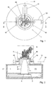
- Fig. 1 shows a top plan view of an exemplary embodiment;
- Fig. 2 shows a cross-sectional view along line II-II of the top plan view shown in Fig. 1;
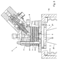
- Fig. 3 shows detail Q of the cross-sectional view shown in Fig. 2.
- Figs. 1-3 show an apparatus for treating a surface of a substrate S. The apparatus is particularly arranged for carrying out PECVD. The apparatus is provided with a
process chamber 1 and asubstrate holder 2 arranged there, on which the substrate S to be treated is placed. On theprocess chamber 1 and opposite the substrate surface to be treated, aplasma source 3 is mounted. - As Fig. 3 shows, the plasma source is a
cascade source 3. Thesource 3 is provided with acathode 4 located in aprechamber 6 and ananode 5 located on a side of thesource 3 facing theprocess chamber 1. Via a relativelynarrow channel 7, theprechamber 6 opens into theprocess chamber 1. Thechannel 7 is bounded by mutually electricallyinsulated cascade plates 8 and theanode 5. During use, theprocess chamber 1 is maintained at a relatively low pressure, in particular lower than 5000 Pa, and preferably lower than 500 Pa. Between thocathode 4 andanode 5, a plasma is generated, for instance by ignition of an inert gas, or fluid otherwise suitable for this, present between them. When the plasma has been generated in thesource 3, the pressure P2 in theprechamber 6 is higher than the pressure in theprocess chamber 1. The pressure P2 can, for instance, be substantially atmospheric and be in the range of 0.5-1.5 bar. Because the pressure in theprocess chamber 1 is considerably lower than the pressure in theprechamber 6, apart 20 of the generated plasma expands such that it extends, via the relativelynarrow channel 7, into theprocess chamber 1 to contact the substrate surface. - The
plasma source 3 is movably arranged relative to the substrate surface. For this purpose, theplasma source 3 is mounted on anupper housing part 16 of the apparatus. Theupper housing part 16 is coupled to alower housing part 17 by means of a flexible, substantially gastight sealing. In the present exemplary embodiment, the sealing is designed as a cylindricalresilient body 11. In addition, theresilient body 11 is arranged to exert such a spring force on the at least oneplasma source 3, at least via theupper housing part 16, that, under the influence of that spring force, each time, theplasma source 3 can move to the starting position shown in the Figures when theplasma source 3 has been brought to another position. In the present exemplary embodiment, theresilient body 11 is formed by a thin-walled stainless-steel bellows. - For the purpose of moving the
plasma source 3, theupper housing part 16 is coupled to thelower housing part 17 so as to be rotatable about twodifferent axes upper housing part 16 is connected to abearing ring 19 so as to be rotatable about arotation axis 15, while thisbearing ring 19 is connected, so as to be rotatable about arotation axis 14, tosupports 18 attached on thelower housing part 17. The apparatus is provided with afirst motor 12 and asecond motor 13 to move theupper housing part 16 with thesource 3 to a desired position. Since the tworotation axes plasma source 3 can be moved to very many different positions. - As Figs. 2 and 3 show, the
process chamber 1 is provided with ashowerhead 9. The showerhead is arranged to add the treatment fluid to theplasma 20 extending via the relativelynarrow channel 7 into theprocess chamber 1. in particular for carrying out PECVD. Theshowerhead 9 is provided with at least oneplasma passage 21 through which theplasma 20 can extend. The showerhead can, for instance, comprise an annular pipe provided with a number ofoutflow openings 22 through which the treatment fluid can be introduced into theplasma 20. Theshowerhead 9 is coupled to theplasma source 3, at least via theupper housing part 16, so that theshowerhead 9 can follow movements of theplasma source 3. - During use of this apparatus, the
plasma source 3 can be moved to obtain a very good control of a plasma treatment of the substrate surface. This is particularly advantageous since this allows, for instance, material to be deposited on the substrate S with a very uniform layer thickness. The upper housing part with thesource 3 can, for instance, be moved such that parts of the substrate surface which receive too little plasma, for instance near the edge of the substrate, receive an extra amount of plasma to still undergo sufficient treatment. On the other hand, material can, conversely, be dry etched from the substrate surface in a very uniform manner. In addition, by movement of thesource 3, it can be achieved that certain parts of the substrate surface undergo a considerably greater extent of treatment than other parts. For instance, substantially a half of the substrate surface can be treated by a rotation of the source about one of the tworotation axes - It is self-evident that the invention is not limited to the exemplary embodiment described. Various modifications are possible within the scope of the invention. For instance, the wording that the at least one source "is mounted on the process chamber" should be interpreted broadly, and can, for instance, include the meaning that the source is mounted on top of, next to, near, under the process chamber or otherwise with respect to the process chamber, but at least such that at least a part of a plasma generated by this source can reach a surface of a substrate S arranged in the process chamber.
- Further, the process chamber can be arranged to place one or more than one substrate in it.
- A substrate to be treated may, for instance, comprise a semiconductor wafer, a compact or DVD disk such as for storage of music, video, computer data, a solar cell substrate, a display substrate, a reflector, a window, a car window, a synthetic or metal substrate to be coated, a housing, a lamp housing, a catalyst substrate or the like. The substrate may have a disc-shaped, circular, angular or other design. The substrate can, for instance, comprise a three-dimensional object. The surface of the substrate to be treated can, for instance, comprise an inside and/or an outside of the substrate. Further, the substrate surface to be treated can, for instance, comprise a substantially one-dimensional, two-dimensional or three-dimensional surface, an at least partly concave surface, an at least partly convex surface, and/or a combination of similar or differently shaped surfaces.
- The material to be deposited by PECVD may comprise various materials, an enumeration of which is outside the scope of this text, but a reference to the elements of the periodic table and possible atomic and/or molecular combinations of these elements gives a fair impression of what can be deposited. The invention is not limited to a movable source but also comprises a fixedly arranged source with a movable treatment fluid supply source. The invention also comprises a method and apparatus provided with multiple movable sources and/or movable treatment fluid supply sources.
- Further, the substrate S to be treated and/or the
substrate holder 2 can, for instance, also be movably arranged, to be moved during a substrate treatment. - Further, the plasma source and/or the treatment fluid supply source can be moved continuously, at certain moments, iteratively, intermittently, periodically or the like. The movement of the plasma source and/or the treatment fluid supply source can, for instance, be started after the substrate has been placed in a certain treatment position in the process chamber.
Claims (30)
- A method for treating a surface of at least one substrate, wherein the at least one substrate is placed in a process chamber, , wherein a plasma is generated by at least one plasma source, the at least one plasma source being a cascade source (3), wherein at least one cathode (4) of the cascade source (3) is present in a prechamber (6) in which, during use, a relatively high pressure (P2) prevails compared to a relatively low pressure (P1) prevailing in the process chamber (1), wherein, via a relatively narrow channel (7) bounded by mutually electrically insulated cascade plates (8), the prechamber (6) opens into the process chamber (1), such that, during use, the plasma extends via the relatively narrow channel (7) into the process chamber (1), characterized in that, during the treatment, at least one plasma source (3) and/or at least one optionally provided treatment fluid supply source is moved relative to the substrate surface.
- A method according to claim 1, characterized in that the plasma source (3) and/or the optional treatment fluid supply source is rotated about at least one rotation axis (14, 15), which axis (14, 15) extends substantially parallel to the substrate surface.
- A method according to claim 1 or 2, characterized in that the plasma source (3) and/or the optional treatment fluid supply source is moved in a direction towards the substrate surface or away from it.
- A method according to any one of the preceding claims, characterized in that the plasma source (3) and/or the optional treatment fluid supply source is moved in at least one lateral direction relative to the substrate surface.
- A method according to any one of the preceding claims, characterized in that the plasma source (3) and/or the optional treatment fluid supply source is rotated about an axis extending perpendicularly relative to the substrate surface.
- A method according to any one of the preceding claims, characterized in that a treatment fluid is added to the plasma, in particular for the purpose of PECVD.
- A method according to claim 6, characterized in that the amount of treatment fluid to be added to the plasma is related to the movement of the at least one plasma source (3).
- A method according to claim 6 or 7, characterized in that a treatment fluid is supplied into a prechamber (6) of the cascade source (3), near a cascade source cathode (4) present in this prechamber (6).
- A method according to at least claim 6 or 7, characterized in that, between the at least one plasma source (3) and the substrate surface, at least one treatment fluid supply source (9) is arranged to add the treatment fluid to the plasma.
- A method according to claim 9, characterized in that, during the treatment, the at least one treatment fluid supply source (9) is moved relative to the substrate surface, wherein the movement of the treatment fluid supply source (9) is related to the movement of the at least one plasma source (3).
- A method according to any one of the preceding claims, characterized in that the at least one plasma source (3) is moved such that each part of the substrate surface undergoes substantially the same extent of treatment, in particular in that each part of this surface is reached by the same amount of plasma.
- A method according to any one of claims 1-10, characterized in that the at least one plasma source (3) is moved such that at least a first part of the substrate surface undergoes substantially a greater extent of treatment than a second part of this surface, in particular in that the first surface part is reached by a larger amount of plasma than the second surface part.
- A method according to any one of the preceding claims, wherein said plasma source (3) is mounted on the process chamber.
- A method according to any one of claims 1-12, wherein said substrate is provided with at least one cavity at least partly bounded by said substrate surface, wherein, during treatment, at least a part of said plasma source and/or at least said treatment fluid supply source is and/or has been introduced into said substrate cavity.
- A method according to any one of the preceding claims, wherein, during the treatment, said plasma source (3) and/or treatment fluid supply source carries out at least one three-dimensional movement.
- An apparatus for treating a surface of at least one substrate, wherein the apparatus is provided with a process chamber and at least one plasma source, the at least one plasma source being a cascade source (3), wherein at least one cathode (4) of the cascade source (3) is present in a prechamber (6) in which, during use, a relatively high pressure (P2) prevails compared to a relatively low pressure (P1) prevailing in the process chamber (1), wherein, via a relatively narrow channel (7) bounded by mutually electrically insulated cascade plates (8), the prechamber (6) opens into the process chamber (1), such that, during use, the plasma extends via the relatively narrow channel (7) into the process chamber (1), characterized in that the at least one plasma source (3) and/or at least one optionally provided treatment fluid supply source is movably arranged.
- An apparatus according to claim 16, characterized in that the apparatus is provided with resilient means (11) arranged to exert such a spring force on the at least one plasma source (3) that, under the influence of this spring force, the plasma source (3) can move to a starting position when the plasma source (3) is not in this starting position.
- An apparatus according to any one of claims 16-17, characterized in that, between the at least one plasma source (3) and the process chamber (1), a flexible, substantially gastight sealing is provided.
- An apparatus according to any one of claims 16-18, characterized in that the apparatus is provided with a first housing part (16) and a second housing part (17), wherein the at least one plasma source is provided on the first housing part (16), wherein the first housing part (16) is coupled to the second housing part (17) in a substantially gastight and movable manner, in particular by a thin-walled stainless-steel bellows (11).
- An apparatus according to any one of claims 16-19, characterized in that the apparatus is provided with at least one motor (12, 13) for the purpose of moving the at least one plasma source (3).
- An apparatus according to any one of claims 16-20, characterized in that the at least one plasma source (3) is arranged so as to be rotatable about at least one first (14) rotation axis and one second rotation axis (15), wherein the first and second rotation axis (14 and 15 respectively) each extend substantially parallel to the substrate surface and in a different direction.
- An apparatus according to any one of claims 16-21, characterized in that the process chamber (1) is provided with at least one treatment fluid supply source (9) to add a treatment fluid to the plasma, in particular for the purpose of PECVD.
- An apparatus according to claim 22, characterized in that the at least one treatment fluid supply source (9) is arranged to add treatment fluid to the plasma extending via each relatively narrow cascade source channel (7) into the process chamber (1).
- An apparatus according to claim 22 or 23, characterized in that the at least one treatment fluid supply source (9) is provided with at least one plasma passage through which the plasma extends during use.
- An apparatus according to any one of claims 22-24, characterized in that the at least one treatment fluid supply source (9) is movably arranged in the process chamber (1).
- An apparatus according to claim 25, characterized in that the at least one treatment fluid supply source (9) is coupled to the at least one plasma source, such that the movement of the at least one treatment fluid supply source (9) is related to the movement of the at least one plasma source (3).
- An apparatus according to any one of claims 16-26, wherein said plasma source is mounted on the process chamber.
- An apparatus according to any one of claims 16-27, wherein said plasma source and/or at least said treatment fluid supply source are arranged to carry out one or more three-dimensional movements.
- An apparatus according to any one of claims 16-28, wherein the apparatus is at least arranged to carry out PECVD.
- A substrate provided with a surface with at least one layer of material deposited on it, characterized in that the layer has been deposited using a method according to any one of claims 1-15 and/or using an apparatus according to any one of claims 16-29.
Applications Claiming Priority (3)
| Application Number | Priority Date | Filing Date | Title |
|---|---|---|---|
| NL1022155 | 2002-12-12 | ||
| NL1022155A NL1022155C2 (en) | 2002-12-12 | 2002-12-12 | Method and device for treating a surface of at least one substrate. |
| PCT/NL2003/000886 WO2004053190A1 (en) | 2002-12-12 | 2003-12-12 | Method and apparatus for treating a substrate |
Publications (2)
| Publication Number | Publication Date |
|---|---|
| EP1604049A1 EP1604049A1 (en) | 2005-12-14 |
| EP1604049B1 true EP1604049B1 (en) | 2007-03-28 |
Family
ID=32501543
Family Applications (1)
| Application Number | Title | Priority Date | Filing Date |
|---|---|---|---|
| EP03782978A Expired - Lifetime EP1604049B1 (en) | 2002-12-12 | 2003-12-12 | Method and apparatus for treating a substrate |
Country Status (11)
| Country | Link |
|---|---|
| US (1) | US7645495B2 (en) |
| EP (1) | EP1604049B1 (en) |
| JP (1) | JP4578979B2 (en) |
| KR (1) | KR100895913B1 (en) |
| CN (1) | CN100489155C (en) |
| AT (1) | ATE358192T1 (en) |
| AU (1) | AU2003296050A1 (en) |
| DE (1) | DE60312902T2 (en) |
| ES (1) | ES2283848T3 (en) |
| NL (1) | NL1022155C2 (en) |
| WO (1) | WO2004053190A1 (en) |
Families Citing this family (53)
| Publication number | Priority date | Publication date | Assignee | Title |
|---|---|---|---|---|
| WO2005081592A1 (en) * | 2004-02-20 | 2005-09-01 | The University Of Sydney | An apparatus for plasma treatment |
| US20090107545A1 (en) | 2006-10-09 | 2009-04-30 | Soltaix, Inc. | Template for pyramidal three-dimensional thin-film solar cell manufacturing and methods of use |
| US9508886B2 (en) | 2007-10-06 | 2016-11-29 | Solexel, Inc. | Method for making a crystalline silicon solar cell substrate utilizing flat top laser beam |
| US8399331B2 (en) | 2007-10-06 | 2013-03-19 | Solexel | Laser processing for high-efficiency thin crystalline silicon solar cell fabrication |
| US8420435B2 (en) | 2009-05-05 | 2013-04-16 | Solexel, Inc. | Ion implantation fabrication process for thin-film crystalline silicon solar cells |
| NL1030896C2 (en) * | 2006-01-11 | 2007-07-12 | Otb Group Bv | Method and device for the controlled depositing of material by means of plasma on a three-dimensional substrate. |
| BRPI0710139A2 (en) * | 2006-04-14 | 2011-08-23 | Silica Tech Llc | PLASMA DEPOSITION APPARATUS TO MAKE SOLAR CELLS, AND, METHOD FOR FORMING A SOLAR CELL LAYER |
| US20080210290A1 (en) * | 2006-04-14 | 2008-09-04 | Dau Wu | Plasma inside vapor deposition apparatus and method for making multi-junction silicon thin film solar cell modules and panels |
| WO2008007944A1 (en) * | 2006-07-12 | 2008-01-17 | Technische Universiteit Eindhoven | Method and device for treating a substrate by means of a plasma |
| US20100304521A1 (en) * | 2006-10-09 | 2010-12-02 | Solexel, Inc. | Shadow Mask Methods For Manufacturing Three-Dimensional Thin-Film Solar Cells |
| US8035028B2 (en) * | 2006-10-09 | 2011-10-11 | Solexel, Inc. | Pyramidal three-dimensional thin-film solar cells |
| US8193076B2 (en) | 2006-10-09 | 2012-06-05 | Solexel, Inc. | Method for releasing a thin semiconductor substrate from a reusable template |
| US8293558B2 (en) * | 2006-10-09 | 2012-10-23 | Solexel, Inc. | Method for releasing a thin-film substrate |
| US7999174B2 (en) * | 2006-10-09 | 2011-08-16 | Solexel, Inc. | Solar module structures and assembly methods for three-dimensional thin-film solar cells |
| WO2011072161A2 (en) | 2009-12-09 | 2011-06-16 | Solexel, Inc. | High-efficiency photovoltaic back-contact solar cell structures and manufacturing methods using thin planar semiconductors |
| US20080264477A1 (en) * | 2006-10-09 | 2008-10-30 | Soltaix, Inc. | Methods for manufacturing three-dimensional thin-film solar cells |
| USH2207H1 (en) * | 2007-01-05 | 2007-12-04 | Bijker Martin D | Additional post-glass-removal processes for enhanced cell efficiency in the production of solar cells |
| WO2009026240A1 (en) * | 2007-08-17 | 2009-02-26 | Solexel, Inc. | Methods for liquid transfer coating of three-dimensional substrates |
| US8039052B2 (en) * | 2007-09-06 | 2011-10-18 | Intermolecular, Inc. | Multi-region processing system and heads |
| US20100144080A1 (en) * | 2008-06-02 | 2010-06-10 | Solexel, Inc. | Method and apparatus to transfer coat uneven surface |
| US8288195B2 (en) * | 2008-11-13 | 2012-10-16 | Solexel, Inc. | Method for fabricating a three-dimensional thin-film semiconductor substrate from a template |
| US8294026B2 (en) | 2008-11-13 | 2012-10-23 | Solexel, Inc. | High-efficiency thin-film solar cells |
| EP2371006A4 (en) * | 2008-11-26 | 2013-05-01 | Solexel Inc | TRUNCATED PYRAMID STRUCTURES FOR TRANSPARENT SOLAR CELLS |
| MY170119A (en) * | 2009-01-15 | 2019-07-05 | Trutag Tech Inc | Porous silicon electro-etching system and method |
| US9076642B2 (en) | 2009-01-15 | 2015-07-07 | Solexel, Inc. | High-Throughput batch porous silicon manufacturing equipment design and processing methods |
| US8906218B2 (en) | 2010-05-05 | 2014-12-09 | Solexel, Inc. | Apparatus and methods for uniformly forming porous semiconductor on a substrate |
| US8999058B2 (en) | 2009-05-05 | 2015-04-07 | Solexel, Inc. | High-productivity porous semiconductor manufacturing equipment |
| MY162405A (en) * | 2009-02-06 | 2017-06-15 | Solexel Inc | Trench Formation Method For Releasing A Thin-Film Substrate From A Reusable Semiconductor Template |
| US8828517B2 (en) | 2009-03-23 | 2014-09-09 | Solexel, Inc. | Structure and method for improving solar cell efficiency and mechanical strength |
| EP2419306B1 (en) * | 2009-04-14 | 2016-03-30 | Solexel, Inc. | High efficiency epitaxial chemical vapor deposition (cvd) reactor |
| US9099584B2 (en) * | 2009-04-24 | 2015-08-04 | Solexel, Inc. | Integrated three-dimensional and planar metallization structure for thin film solar cells |
| US9318644B2 (en) | 2009-05-05 | 2016-04-19 | Solexel, Inc. | Ion implantation and annealing for thin film crystalline solar cells |
| US8445314B2 (en) * | 2009-05-22 | 2013-05-21 | Solexel, Inc. | Method of creating reusable template for detachable thin film substrate |
| MY159405A (en) * | 2009-05-29 | 2016-12-30 | Solexel Inc | Three-dimensional thin-film semiconductor substrate with through-holes and methods of manufacturing |
| NL2002980C2 (en) * | 2009-06-05 | 2010-12-07 | Otb Solar Bv | Method for passivating al least a part of a substrate surface. |
| US9111729B2 (en) * | 2009-12-03 | 2015-08-18 | Lam Research Corporation | Small plasma chamber systems and methods |
| CN102844883B (en) | 2010-02-12 | 2016-01-20 | 速力斯公司 | Double-sided reusable templates for semiconductor substrates for fabrication of photovoltaic cells and microelectronic devices |
| US9190289B2 (en) | 2010-02-26 | 2015-11-17 | Lam Research Corporation | System, method and apparatus for plasma etch having independent control of ion generation and dissociation of process gas |
| EP2580775A4 (en) | 2010-06-09 | 2014-05-07 | Solexel Inc | METHOD AND SYSTEM FOR HIGH-PRODUCTIVITY THIN FILM DEPOSITION |
| MY158500A (en) | 2010-08-05 | 2016-10-14 | Solexel Inc | Backplane reinforcement and interconnects for solar cells |
| US8999104B2 (en) | 2010-08-06 | 2015-04-07 | Lam Research Corporation | Systems, methods and apparatus for separate plasma source control |
| US9155181B2 (en) | 2010-08-06 | 2015-10-06 | Lam Research Corporation | Distributed multi-zone plasma source systems, methods and apparatus |
| US9967965B2 (en) | 2010-08-06 | 2018-05-08 | Lam Research Corporation | Distributed, concentric multi-zone plasma source systems, methods and apparatus |
| US9449793B2 (en) | 2010-08-06 | 2016-09-20 | Lam Research Corporation | Systems, methods and apparatus for choked flow element extraction |
| CN102534568B (en) * | 2010-12-30 | 2014-12-17 | 北京北方微电子基地设备工艺研究中心有限责任公司 | Plasma-enhanced chemical vapor deposition equipment |
| EP2710639A4 (en) | 2011-05-20 | 2015-11-25 | Solexel Inc | SELF-ACTIVATED FRONT SURFACE POLARIZATION FOR A SOLAR CELL |
| CN102796993B (en) * | 2011-05-27 | 2014-05-28 | 北京北方微电子基地设备工艺研究中心有限责任公司 | CVD (Chemical Vapor Deposition) equipment and control method thereof |
| US9177762B2 (en) | 2011-11-16 | 2015-11-03 | Lam Research Corporation | System, method and apparatus of a wedge-shaped parallel plate plasma reactor for substrate processing |
| US10283325B2 (en) | 2012-10-10 | 2019-05-07 | Lam Research Corporation | Distributed multi-zone plasma source systems, methods and apparatus |
| US9783889B2 (en) * | 2012-03-26 | 2017-10-10 | Applied Materials, Inc. | Apparatus for variable substrate temperature control |
| US8735210B2 (en) * | 2012-06-28 | 2014-05-27 | International Business Machines Corporation | High efficiency solar cells fabricated by inexpensive PECVD |
| WO2014098905A1 (en) * | 2012-12-21 | 2014-06-26 | Clearedge Power Corporation | Deposition cloud tower with adjustable field |
| JP2015090916A (en) * | 2013-11-06 | 2015-05-11 | 東京エレクトロン株式会社 | Substrate processing apparatus and substrate processing method |
Family Cites Families (16)
| Publication number | Priority date | Publication date | Assignee | Title |
|---|---|---|---|---|
| DE2054538C3 (en) * | 1970-11-05 | 1979-03-22 | Siemens Ag, 1000 Berlin Und 8000 Muenchen | Device for depositing layers of semiconductor material |
| JPS6179774A (en) * | 1984-09-28 | 1986-04-23 | Mitsubishi Heavy Ind Ltd | Method for coating inside surface of vessel |
| FR2571995B1 (en) * | 1984-10-22 | 1986-12-26 | Soudure Autogene Francaise | MACHINE FOR THE EXTERNAL WELDING OF TUBES END TO END, BY ELECTRON BEAM |
| DE3884653T2 (en) * | 1987-04-03 | 1994-02-03 | Fujitsu Ltd | Method and device for the vapor deposition of diamond. |
| JPS6428297A (en) * | 1987-04-03 | 1989-01-30 | Fujitsu Ltd | Vapor phase synthesis of diamond |
| GB8713986D0 (en) | 1987-06-16 | 1987-07-22 | Shell Int Research | Apparatus for plasma surface treating |
| NL8701530A (en) * | 1987-06-30 | 1989-01-16 | Stichting Fund Ond Material | METHOD FOR TREATING SURFACES OF SUBSTRATES USING A PLASMA AND REACTOR FOR CARRYING OUT THAT METHOD |
| JPH06330324A (en) * | 1993-05-17 | 1994-11-29 | Fuji Electric Co Ltd | Dry thin film processing equipment |
| US6051114A (en) * | 1997-06-23 | 2000-04-18 | Applied Materials, Inc. | Use of pulsed-DC wafer bias for filling vias/trenches with metal in HDP physical vapor deposition |
| JP2000109979A (en) * | 1998-10-05 | 2000-04-18 | Tokujiro Okui | Surface treatment method by dc arc discharge plasma |
| US6068201A (en) * | 1998-11-05 | 2000-05-30 | Sulzer Metco (Us) Inc. | Apparatus for moving a thermal spray gun in a figure eight over a substrate |
| JP3662779B2 (en) * | 1999-06-22 | 2005-06-22 | シャープ株式会社 | Plasma processing equipment |
| US6344416B1 (en) * | 2000-03-10 | 2002-02-05 | International Business Machines Corporation | Deliberate semiconductor film variation to compensate for radial processing differences, determine optimal device characteristics, or produce small productions |
| JP2002118027A (en) * | 2000-10-10 | 2002-04-19 | Anelva Corp | Magnetic film forming apparatus and magnetic film forming method |
| US6397776B1 (en) * | 2001-06-11 | 2002-06-04 | General Electric Company | Apparatus for large area chemical vapor deposition using multiple expanding thermal plasma generators |
| US20030049468A1 (en) * | 2001-08-16 | 2003-03-13 | Ing-Feng Hu | Cascade arc plasma and abrasion resistant coatings made therefrom |
-
2002
- 2002-12-12 NL NL1022155A patent/NL1022155C2/en not_active IP Right Cessation
-
2003
- 2003-12-12 EP EP03782978A patent/EP1604049B1/en not_active Expired - Lifetime
- 2003-12-12 KR KR1020057010737A patent/KR100895913B1/en not_active Expired - Fee Related
- 2003-12-12 US US10/538,652 patent/US7645495B2/en not_active Expired - Fee Related
- 2003-12-12 JP JP2004558567A patent/JP4578979B2/en not_active Expired - Fee Related
- 2003-12-12 DE DE60312902T patent/DE60312902T2/en not_active Expired - Lifetime
- 2003-12-12 AT AT03782978T patent/ATE358192T1/en not_active IP Right Cessation
- 2003-12-12 AU AU2003296050A patent/AU2003296050A1/en not_active Abandoned
- 2003-12-12 CN CNB2003801086599A patent/CN100489155C/en not_active Expired - Fee Related
- 2003-12-12 ES ES03782978T patent/ES2283848T3/en not_active Expired - Lifetime
- 2003-12-12 WO PCT/NL2003/000886 patent/WO2004053190A1/en not_active Ceased
Also Published As
| Publication number | Publication date |
|---|---|
| KR100895913B1 (en) | 2009-05-07 |
| ES2283848T3 (en) | 2007-11-01 |
| ATE358192T1 (en) | 2007-04-15 |
| DE60312902T2 (en) | 2007-12-06 |
| CN1738923A (en) | 2006-02-22 |
| EP1604049A1 (en) | 2005-12-14 |
| DE60312902D1 (en) | 2007-05-10 |
| JP2006509907A (en) | 2006-03-23 |
| NL1022155C2 (en) | 2004-06-22 |
| AU2003296050A1 (en) | 2004-06-30 |
| US20060231031A1 (en) | 2006-10-19 |
| CN100489155C (en) | 2009-05-20 |
| WO2004053190A1 (en) | 2004-06-24 |
| KR20050100599A (en) | 2005-10-19 |
| JP4578979B2 (en) | 2010-11-10 |
| US7645495B2 (en) | 2010-01-12 |
Similar Documents
| Publication | Publication Date | Title |
|---|---|---|
| US7645495B2 (en) | Method and apparatus for treating a substrate | |
| US10590534B2 (en) | Film deposition method and film deposition apparatus | |
| CN105088177B (en) | Rear side precipitation equipment and application | |
| US11519067B2 (en) | Method for depositing a silicon nitride film and film deposition apparatus | |
| US6835414B2 (en) | Method for producing coated substrates | |
| US20160343547A1 (en) | Substrate-processing system and method of coating carbon-protection layer therefor | |
| TW201624589A (en) | Method and system for improving process uniformity | |
| WO2005087974A3 (en) | Cvd processes for the deposition of amorphous carbon films | |
| GB2247692A (en) | Preparing diamond-like carbon coatings involving a foundation layer; apparatus therefor | |
| US10781519B2 (en) | Method and apparatus for processing substrate | |
| US11479852B2 (en) | Method for dry cleaning a susceptor and substrate processing apparatus | |
| JP2018048393A (en) | Method for coating conductive components and coating for conductive components | |
| KR20190022054A (en) | Equipment and Method for Doped Coating Using Filtered Cathodic Vacuum Arc | |
| CA2354925A1 (en) | Apparatus and method for coating substrates | |
| EP1054438A3 (en) | System and method for cleaning silicon-coated surfaces in an ion implanter | |
| AU734117B2 (en) | Rotary apparatus for plasma immersion-assisted treament of substrates | |
| KR102867979B1 (en) | Substrate treatment apparatus and substrate treatment method | |
| KR20230062783A (en) | Method and system for selectively removing material at an edge of a substrate | |
| JP2025000255A (en) | Film deposition method and film deposition apparatus | |
| KR20260047825A (en) | Apparatus for processing substrate | |
| KR101619814B1 (en) | Surface contact unit and atomic layer deposition apparatus having the same | |
| KR20240086322A (en) | Batch type atomic layer depositing apparatus | |
| KR100335565B1 (en) | An electrode assembly controlled self dc bias voltage of pecvd | |
| Kim | Structural properties of amorphous carbon thin films deposited by LF (100 kHz), RF (13.56 MHz), and pulsed RF (13.56 MHz) plasma CVD | |
| JP2003003262A (en) | Method for producing hard carbon film-coated member |
Legal Events
| Date | Code | Title | Description |
|---|---|---|---|
| PUAI | Public reference made under article 153(3) epc to a published international application that has entered the european phase |
Free format text: ORIGINAL CODE: 0009012 |
|
| 17P | Request for examination filed |
Effective date: 20050705 |
|
| AK | Designated contracting states |
Kind code of ref document: A1 Designated state(s): AT BE BG CH CY CZ DE DK EE ES FI FR GB GR HU IE IT LI LU MC NL PT RO SE SI SK |
|
| AX | Request for extension of the european patent |
Extension state: AL LT LV MK |
|
| RAX | Requested extension states of the european patent have changed |
Extension state: LT Payment date: 20050705 Extension state: LV Payment date: 20050705 |
|
| GRAP | Despatch of communication of intention to grant a patent |
Free format text: ORIGINAL CODE: EPIDOSNIGR1 |
|
| RIN1 | Information on inventor provided before grant (corrected) |
Inventor name: BIJKER, MARTIN, DINANT Inventor name: EVERS, MARINUS, FRANCISCUS, JOHANUS Inventor name: DINGS, FRANCISCUS, CORNELIUS Inventor name: HOMPUS, MICHAEL, ADRIANUS, THEODORUS |
|
| GRAS | Grant fee paid |
Free format text: ORIGINAL CODE: EPIDOSNIGR3 |
|
| GRAA | (expected) grant |
Free format text: ORIGINAL CODE: 0009210 |
|
| AK | Designated contracting states |
Kind code of ref document: B1 Designated state(s): AT BE BG CH CY CZ DE DK EE ES FI FR GB GR HU IE IT LI LU MC NL PT RO SE SI SK |
|
| AX | Request for extension of the european patent |
Extension state: LT LV |
|
| PG25 | Lapsed in a contracting state [announced via postgrant information from national office to epo] |
Ref country code: BE Free format text: LAPSE BECAUSE OF FAILURE TO SUBMIT A TRANSLATION OF THE DESCRIPTION OR TO PAY THE FEE WITHIN THE PRESCRIBED TIME-LIMIT Effective date: 20070328 Ref country code: AT Free format text: LAPSE BECAUSE OF FAILURE TO SUBMIT A TRANSLATION OF THE DESCRIPTION OR TO PAY THE FEE WITHIN THE PRESCRIBED TIME-LIMIT Effective date: 20070328 Ref country code: SI Free format text: LAPSE BECAUSE OF FAILURE TO SUBMIT A TRANSLATION OF THE DESCRIPTION OR TO PAY THE FEE WITHIN THE PRESCRIBED TIME-LIMIT Effective date: 20070328 Ref country code: FI Free format text: LAPSE BECAUSE OF FAILURE TO SUBMIT A TRANSLATION OF THE DESCRIPTION OR TO PAY THE FEE WITHIN THE PRESCRIBED TIME-LIMIT Effective date: 20070328 |
|
| REG | Reference to a national code |
Ref country code: GB Ref legal event code: FG4D |
|
| REG | Reference to a national code |
Ref country code: CH Ref legal event code: EP |
|
| REF | Corresponds to: |
Ref document number: 60312902 Country of ref document: DE Date of ref document: 20070510 Kind code of ref document: P |
|
| REG | Reference to a national code |
Ref country code: IE Ref legal event code: FG4D |
|
| PG25 | Lapsed in a contracting state [announced via postgrant information from national office to epo] |
Ref country code: SE Free format text: LAPSE BECAUSE OF FAILURE TO SUBMIT A TRANSLATION OF THE DESCRIPTION OR TO PAY THE FEE WITHIN THE PRESCRIBED TIME-LIMIT Effective date: 20070628 |
|
| REG | Reference to a national code |
Ref country code: CH Ref legal event code: NV Representative=s name: PATENTANWAELTE SCHAAD, BALASS, MENZL & PARTNER AG |
|
| PG25 | Lapsed in a contracting state [announced via postgrant information from national office to epo] |
Ref country code: PT Free format text: LAPSE BECAUSE OF FAILURE TO SUBMIT A TRANSLATION OF THE DESCRIPTION OR TO PAY THE FEE WITHIN THE PRESCRIBED TIME-LIMIT Effective date: 20070828 |
|
| LTIE | Lt: invalidation of european patent or patent extension |
Effective date: 20070328 |
|
| ET | Fr: translation filed | ||
| REG | Reference to a national code |
Ref country code: ES Ref legal event code: FG2A Ref document number: 2283848 Country of ref document: ES Kind code of ref document: T3 |
|
| PG25 | Lapsed in a contracting state [announced via postgrant information from national office to epo] |
Ref country code: SK Free format text: LAPSE BECAUSE OF FAILURE TO SUBMIT A TRANSLATION OF THE DESCRIPTION OR TO PAY THE FEE WITHIN THE PRESCRIBED TIME-LIMIT Effective date: 20070328 |
|
| PG25 | Lapsed in a contracting state [announced via postgrant information from national office to epo] |
Ref country code: RO Free format text: LAPSE BECAUSE OF FAILURE TO SUBMIT A TRANSLATION OF THE DESCRIPTION OR TO PAY THE FEE WITHIN THE PRESCRIBED TIME-LIMIT Effective date: 20070328 Ref country code: CZ Free format text: LAPSE BECAUSE OF FAILURE TO SUBMIT A TRANSLATION OF THE DESCRIPTION OR TO PAY THE FEE WITHIN THE PRESCRIBED TIME-LIMIT Effective date: 20070328 |
|
| PG25 | Lapsed in a contracting state [announced via postgrant information from national office to epo] |
Ref country code: DK Free format text: LAPSE BECAUSE OF FAILURE TO SUBMIT A TRANSLATION OF THE DESCRIPTION OR TO PAY THE FEE WITHIN THE PRESCRIBED TIME-LIMIT Effective date: 20070328 |
|
| PLBE | No opposition filed within time limit |
Free format text: ORIGINAL CODE: 0009261 |
|
| STAA | Information on the status of an ep patent application or granted ep patent |
Free format text: STATUS: NO OPPOSITION FILED WITHIN TIME LIMIT |
|
| 26N | No opposition filed |
Effective date: 20080102 |
|
| PG25 | Lapsed in a contracting state [announced via postgrant information from national office to epo] |
Ref country code: GR Free format text: LAPSE BECAUSE OF FAILURE TO SUBMIT A TRANSLATION OF THE DESCRIPTION OR TO PAY THE FEE WITHIN THE PRESCRIBED TIME-LIMIT Effective date: 20070629 |
|
| PG25 | Lapsed in a contracting state [announced via postgrant information from national office to epo] |
Ref country code: MC Free format text: LAPSE BECAUSE OF NON-PAYMENT OF DUE FEES Effective date: 20071231 |
|
| PG25 | Lapsed in a contracting state [announced via postgrant information from national office to epo] |
Ref country code: IE Free format text: LAPSE BECAUSE OF NON-PAYMENT OF DUE FEES Effective date: 20071212 |
|
| PG25 | Lapsed in a contracting state [announced via postgrant information from national office to epo] |
Ref country code: EE Free format text: LAPSE BECAUSE OF FAILURE TO SUBMIT A TRANSLATION OF THE DESCRIPTION OR TO PAY THE FEE WITHIN THE PRESCRIBED TIME-LIMIT Effective date: 20070328 |
|
| PG25 | Lapsed in a contracting state [announced via postgrant information from national office to epo] |
Ref country code: CY Free format text: LAPSE BECAUSE OF FAILURE TO SUBMIT A TRANSLATION OF THE DESCRIPTION OR TO PAY THE FEE WITHIN THE PRESCRIBED TIME-LIMIT Effective date: 20070328 |
|
| PG25 | Lapsed in a contracting state [announced via postgrant information from national office to epo] |
Ref country code: BG Free format text: LAPSE BECAUSE OF FAILURE TO SUBMIT A TRANSLATION OF THE DESCRIPTION OR TO PAY THE FEE WITHIN THE PRESCRIBED TIME-LIMIT Effective date: 20070628 Ref country code: LU Free format text: LAPSE BECAUSE OF NON-PAYMENT OF DUE FEES Effective date: 20071212 |
|
| PG25 | Lapsed in a contracting state [announced via postgrant information from national office to epo] |
Ref country code: HU Free format text: LAPSE BECAUSE OF FAILURE TO SUBMIT A TRANSLATION OF THE DESCRIPTION OR TO PAY THE FEE WITHIN THE PRESCRIBED TIME-LIMIT Effective date: 20070929 |
|
| REG | Reference to a national code |
Ref country code: CH Ref legal event code: PUE Owner name: OTB SOLAR B.V. Free format text: OTB GROUP B.V.#LUCHTHAVENWEG 10#5657 EB EINDHOVEN (NL) -TRANSFER TO- OTB SOLAR B.V.#LUCHTHAVENWEG 10#5657 EB EINDHOVEN (NL) |
|
| REG | Reference to a national code |
Ref country code: GB Ref legal event code: 732E Free format text: REGISTERED BETWEEN 20091112 AND 20091118 |
|
| NLS | Nl: assignments of ep-patents |
Owner name: OTB SOLAR B.V. Effective date: 20091022 |
|
| REG | Reference to a national code |
Ref country code: FR Ref legal event code: TP |
|
| REG | Reference to a national code |
Ref country code: ES Ref legal event code: PC2A |
|
| PGFP | Annual fee paid to national office [announced via postgrant information from national office to epo] |
Ref country code: ES Payment date: 20111216 Year of fee payment: 9 Ref country code: CH Payment date: 20111227 Year of fee payment: 9 |
|
| PGFP | Annual fee paid to national office [announced via postgrant information from national office to epo] |
Ref country code: IT Payment date: 20111228 Year of fee payment: 9 |
|
| REG | Reference to a national code |
Ref country code: CH Ref legal event code: PL |
|
| PG25 | Lapsed in a contracting state [announced via postgrant information from national office to epo] |
Ref country code: LI Free format text: LAPSE BECAUSE OF NON-PAYMENT OF DUE FEES Effective date: 20121231 Ref country code: CH Free format text: LAPSE BECAUSE OF NON-PAYMENT OF DUE FEES Effective date: 20121231 |
|
| PG25 | Lapsed in a contracting state [announced via postgrant information from national office to epo] |
Ref country code: IT Free format text: LAPSE BECAUSE OF NON-PAYMENT OF DUE FEES Effective date: 20121212 |
|
| REG | Reference to a national code |
Ref country code: ES Ref legal event code: FD2A Effective date: 20140307 |
|
| PG25 | Lapsed in a contracting state [announced via postgrant information from national office to epo] |
Ref country code: ES Free format text: LAPSE BECAUSE OF NON-PAYMENT OF DUE FEES Effective date: 20121213 |
|
| PGFP | Annual fee paid to national office [announced via postgrant information from national office to epo] |
Ref country code: GB Payment date: 20141230 Year of fee payment: 12 |
|
| PGFP | Annual fee paid to national office [announced via postgrant information from national office to epo] |
Ref country code: NL Payment date: 20141219 Year of fee payment: 12 |
|
| PGFP | Annual fee paid to national office [announced via postgrant information from national office to epo] |
Ref country code: DE Payment date: 20150227 Year of fee payment: 12 |
|
| PGFP | Annual fee paid to national office [announced via postgrant information from national office to epo] |
Ref country code: FR Payment date: 20141230 Year of fee payment: 12 |
|
| REG | Reference to a national code |
Ref country code: DE Ref legal event code: R119 Ref document number: 60312902 Country of ref document: DE |
|
| GBPC | Gb: european patent ceased through non-payment of renewal fee |
Effective date: 20151212 |
|
| REG | Reference to a national code |
Ref country code: NL Ref legal event code: MM Effective date: 20160101 |
|
| REG | Reference to a national code |
Ref country code: FR Ref legal event code: ST Effective date: 20160831 |
|
| PG25 | Lapsed in a contracting state [announced via postgrant information from national office to epo] |
Ref country code: GB Free format text: LAPSE BECAUSE OF NON-PAYMENT OF DUE FEES Effective date: 20151212 Ref country code: DE Free format text: LAPSE BECAUSE OF NON-PAYMENT OF DUE FEES Effective date: 20160701 Ref country code: NL Free format text: LAPSE BECAUSE OF NON-PAYMENT OF DUE FEES Effective date: 20160101 |
|
| PG25 | Lapsed in a contracting state [announced via postgrant information from national office to epo] |
Ref country code: FR Free format text: LAPSE BECAUSE OF NON-PAYMENT OF DUE FEES Effective date: 20151231 |