EP1602809B1 - Mounting structure of thermostat - Google Patents
Mounting structure of thermostat Download PDFInfo
- Publication number
- EP1602809B1 EP1602809B1 EP04716007A EP04716007A EP1602809B1 EP 1602809 B1 EP1602809 B1 EP 1602809B1 EP 04716007 A EP04716007 A EP 04716007A EP 04716007 A EP04716007 A EP 04716007A EP 1602809 B1 EP1602809 B1 EP 1602809B1
- Authority
- EP
- European Patent Office
- Prior art keywords
- thermostat
- annular
- valve body
- chamber
- mounting structure
- Prior art date
- Legal status (The legal status is an assumption and is not a legal conclusion. Google has not performed a legal analysis and makes no representation as to the accuracy of the status listed.)
- Expired - Lifetime
Links
- 239000002826 coolant Substances 0.000 claims description 36
- 238000002485 combustion reaction Methods 0.000 abstract description 19
- 238000007789 sealing Methods 0.000 abstract description 11
- 238000001816 cooling Methods 0.000 abstract description 5
- 239000012809 cooling fluid Substances 0.000 abstract 6
- 230000002093 peripheral effect Effects 0.000 abstract 3
- XLYOFNOQVPJJNP-UHFFFAOYSA-N water Substances O XLYOFNOQVPJJNP-UHFFFAOYSA-N 0.000 description 8
- 238000006073 displacement reaction Methods 0.000 description 3
- 238000006243 chemical reaction Methods 0.000 description 2
- 238000010276 construction Methods 0.000 description 2
- 239000000126 substance Substances 0.000 description 2
- 230000000694 effects Effects 0.000 description 1
- 238000011144 upstream manufacturing Methods 0.000 description 1
Images


Classifications
-
- F—MECHANICAL ENGINEERING; LIGHTING; HEATING; WEAPONS; BLASTING
- F01—MACHINES OR ENGINES IN GENERAL; ENGINE PLANTS IN GENERAL; STEAM ENGINES
- F01P—COOLING OF MACHINES OR ENGINES IN GENERAL; COOLING OF INTERNAL-COMBUSTION ENGINES
- F01P7/00—Controlling of coolant flow
- F01P7/14—Controlling of coolant flow the coolant being liquid
- F01P7/16—Controlling of coolant flow the coolant being liquid by thermostatic control
-
- G—PHYSICS
- G05—CONTROLLING; REGULATING
- G05D—SYSTEMS FOR CONTROLLING OR REGULATING NON-ELECTRIC VARIABLES
- G05D23/00—Control of temperature
- G05D23/01—Control of temperature without auxiliary power
- G05D23/13—Control of temperature without auxiliary power by varying the mixing ratio of two fluids having different temperatures
- G05D23/1306—Control of temperature without auxiliary power by varying the mixing ratio of two fluids having different temperatures for liquids
- G05D23/132—Control of temperature without auxiliary power by varying the mixing ratio of two fluids having different temperatures for liquids with temperature sensing element
- G05D23/1333—Control of temperature without auxiliary power by varying the mixing ratio of two fluids having different temperatures for liquids with temperature sensing element measuring the temperature of incoming fluid
Definitions
- the present invention relates to a thermostat mounting structure for holding a thermostat that controls the flow of a coolant in a cooling system included in an internal combustion engine.
- a buried thermostat mounting structure previously proposed in, for example, JP 2002-39433 A fits an encased thermostat in a thermostat chamber extending across a coolant passage in a casing, and covers the thermostat chamber with a cover so as to hold the thermostat in place, and seals the gap between the cover and the casing with a rubber seal.
- thermostat mounting structure in a second embodiment of the invention disclosed in JP 2002-39433 A will be described with reference to Fig. 17 .
- a thermostat chamber 03 is extended across a coolant passage 02 formed in a casing 01.
- a thermostat 07 is fitted in the thermostat chamber 03.
- a cover 05 is attached to the casing 04 so as to cover the thermostat chamber 03 and to hold the thermostat 07 in place.
- the gap between the cover 05 and the casing 01 is sealed with a rubber seal 04.
- the thermostat 07 has a cylindrical valve body 08 provided with an inlet opening 08a and an outlet opening 08b, and a valve element 09.
- the valve element 09 moves axially to open and close the inlet opening 08a and the outlet opening 08b.
- the valve body 08 is fitted in the thermostat chamber 03 with the openings 08a and 08b corresponding to the coolant passage 02 of the casing 01.
- a bypass opening 08c is formed in the valve body 08 at a position below the outlet opening 08b so as to connect a space in the valve body 08 to the coolant passage 02.
- the outlet opening 08b and the bypass opening 08c are opened selectively by the agency of the thermal expansion of a wax 010.
- An O-ring 011 is put on the thermostat 07 to divide the outer surface of the valve body 08 into a part on the side of the inlet opening 08a and a part on the side of the outlet opening 08b.
- the cover 05 is provided with a bypass passage 06 and an annular groove holding the rubber seal 04.
- the cover 05 is attached to the casing 01 so as to cover the thermostat chamber 03 holding the thermostat 07.
- the rubber seal 04 is pressed against a part of the casing 01 around the thermostat chamber 03 and the outer end of the valve body 08 to fix the thermostat 07 in the thermostat chamber 03.
- the O-ring 011 divides the thermostat chamber 03 formed in the casing 01 and surrounding the valve body 08 into a part on the side of the inlet opening and a part on the side of the outlet opening.
- the rubber seal 04 separates an internal space inside the valve body 08 fitted in the thermostat chamber 03 from an external space outside the valve body 08.
- the prior art thermostat mounting structure is advantageous in forming a thermostat unit in compact construction, the thermostat 07 fitted in the thermostat chamber 03 is displaced minutely because the thermostat 07 is suspended by the O ring 011 in a floating state, and the thermostat mounting structure does not have any positioning mechanism for positioning the thermostat 07 relative to the casing 01 and the rubber seal 04.
- US-A-5 018 664 discloses a thermostat mounting structure, wherein a thermostat chamber is provided in a casing so as to extend across an inlet coolant passage formed through the casing; a thermostat is fitted in the thermostat chamber of the casing, said thermostat having a valve element slidably fitted in a valve body; a cover is attached to the casing so as to close the thermostat chamber; and an annular elastic seal is provided to seal the thermostat chamber and to hold the thermostat fixedly in place in the thermostat chamber, wherein the elastic seal has a corner part defined by an annular lip and an annular ridge
- EP 1 219 879 A1 discloses a thermostat mounting structure having a thermostat chamber, a thermostat and a cover closing the thermostat chamber, wherein an elastic seal is fitted in an annular groove of the cover to seal the thermostat chamber.
- the present invention has been made in view of such a problem and it is therefore an object of the present invention to provide a thermostat mounting structure capable of accurately positioning and securely sealing a thermostat in a thermostat chamber, and simple in construction.
- the present invention provides a thermostat mounting structure according to claim 1.
- the cover is attached to the casing so as to cover the thermostat chamber with the annular inner corner part of the annular elastic seal fitted in the annular groove of the cover pressed against the outer end of the valve body.
- the thermostat can be held fixedly in place by the simple thermostat mounting structure, the valve body is restrained from displacement, and the annular elastic seal is pressed against the end surface and the circumference of the outer end of the valve body to seal the thermostat chamber with high reliability.
- the elastic seal may be provided with an annular shoulder having an L-shaped cross section in the inner corner part defined by the annular lip and the annular ridge, and the annular circumferential end portion of the outer end of the valve body may be fitted against the annular shoulder to position the thermostat.
- the annular elastic seal is provided with the annular shoulder having an L-shaped cross section in the inner corner part and the cover is attached to the casing to cover the thermostat chamber of the casing with the end surface and the outer circumference of the outer end of the valve body of the thermostat fitted in the thermostat chamber of the casing fitted in the annular groove to position the thermostat, the thermostat can be easily and surely positioned, the valve body can be restrained from displacement, and the elastic seal is pressed against the end surface and the outer circumference of the outer end of the valve body to securely seal the thermostat chamber.
- the annular ridge defining the annular shoulder of the elastic seal may have an inclined inner side surface, and the outer edge of the end surface of the valve body in contact with the inclined inner side surface of the annular ridge may be chambered in a bevel surface.
- the inclined inner side surface of the annular ridge of the elastic seal and the beveled surface of the valve body are able to be pressed closely together and thereby the thermostat can be firmly held for positioning and the sealing effect of the elastic seal can be increased.
- the circular lip of the elastic seal extends radially inward from a body of the elastic seal, and the annular ridge rises toward the thermostat from the inner surface of the body of the elastic seal facing the thermostat.
- an axial groove is formed in the side wall of the thermostat chamber, an axial ridge is formed on the outer circumference of the valve body, and the thermostat is fitted in the thermostat chamber with the axial ridge fitted in the axial groove to position the valve body with respect to a circumferential direction.
- the thermostat chamber of the casing has an outer open end covered with the cover and a substantially semispherical inner bottom
- the cylindrical valve body has an inner, bottomed cylindrical part having an end seated on the semispherical inner bottom of the thermostat chamber.
- the inner, bottomed cylindrical part may have an outside diameter smaller than that of the valve body, ribs may be formed integrally with the inner, bottomed cylindrical end part so as to extend in diametrically opposite directions, respectively, and the ribs may be pressed against the substantially semispherical bottom. This arrangement enables the further accurate positioning of the cylindrical valve body in the thermostat chamber.
- thermostat mounting structure in a preferred embodiment of the present invention will be described with reference to Figs. 1 to 16 .
- the thermostat mounting structure holds a thermostat 50 included in the cooling system of an internal combustion engine.
- a camshaft 2 is supported for rotation on a cylinder head 1.
- a timing chain 4 is extended between a driven sprocket 3 fixedly mounted on one end of the cam shaft 2 and a drive sprocket mounted on a crankshaft, not shown, to drive the camshaft 2 for rotation at a rotational speed half that of the crankshaft.
- the timing chain 4 is extended in a chain chamber 1a formed in the cylinder head 1.
- An opening is formed coaxially with the camshaft 2 in a side wall 1a defining the chain chamber 1a.
- a water pump 5 has a pump case 6 fitted in the opening of the side wall.
- the pump case 6 of the water pump 5 has a bottomed cylindrical part 6a housing a driven magnet 8 supported on a rotational shaft 7, and an enlarged part 6b put on the rotational shaft 7 and housing an impeller 9.
- the rotational shaft 7 has one end rotatably supported on a thermostat casing 20 serving also as a pump cover. The driven magnet 8 and the impeller 9 rotate together with the rotational shaft 7.
- a drive magnet 11 is fitted in a cylindrical support member 10 fastened together with the driven sprocket 3 to the camshaft 2 so as to surround the pump case 6 fitted in the chain chamber 1a of the cylinder head 1.
- the drive magnet 11 that rotates together with the camshaft 2 entrains the driven magnet 8 of the water ump 5 separated therefrom by the pump case 6 to rotate the impeller 9.
- the thermostat casing 20 serving also as a pump cover has an inner annular wall 22.
- the annular wall 22 is fitted in the enlarged part 6b of the pump case 6 to form a scroll chamber 21 in which the impeller 9 rotates.
- a journal 23 of the rotational shaft 7 extends into the thermostat casing 20 as shown in Figs. 1 and 3 .
- the thermostat casing 20 serving also as a thermostat casing has an outer joining surface 24 to which a thermostat cover 30 is joined.
- a thermostat chamber 25, i.e., a thermostat receiving chamber, is formed in the thermostat casing 20 so as to open in the outer contact surface 24.
- a thermostat 50 is fitted in the thermostat chamber 25. Threaded holes 24a are formed in the outer joining surface 24 at positions substantially on the opposite sides, respectively, of the thermostat chamber 25.
- the thermostat chamber 25 is defined by a tapered circumferential surface 25a slightly tapered toward its inner end, and a substantially semispherical bottom surface 25b.
- a groove 25c of a predetermined length is formed in the tapered circumferential surface 25a so as to extend from the open end of the tapered side surface 25a.
- An inlet coolant passage 26 is formed so as to extend perpendicularly to the thermostat chamber 25 and to open in an inner end part of the thermostat chamber 25.
- An upstream part of the inlet coolant passage 26 extends in an inlet connecting pipe 27, while a downstream part of the inlet coolant passage 26 is connected to an annular inlet passage 26a.
- the thermostat chamber 25 extends across the inlet coolant passage 26.
- An outlet coolant passage 29 is formed in an outlet connecting pipe 28 parallel to the inlet connecting pipe 27 as shown in Fig. 4 .
- the inlet coolant passage 29 is connected to the scroll chamber 21 surrounding the impeller 9.
- the thermostat 50 received in the thermostat chamber 25 of the thermostat casing 20 has a slightly tapered, cylindrical valve body 51.
- the valve body 51 is provided with a rectangular inlet opening 52 and a rectangular outlet opening 53 in substantially diametrically opposite parts thereof, and a bypass opening 54 in a part below the outlet opening 53.
- the valve body 51 has an outer open end having an annular end surface 51a, and an inner end defined by a bottom wall 51b.
- a reduced bottomed cylindrical part 55 protrudes from the bottom wall 51b.
- the outer edge of the annular end surface 51a is chamfered in a bevel surface 51c.
- Ribs 56 are extended along the bottomed cylindrical part 55 to the bottom wall 51b. Inner end parts of the ribs 56 are rounded in a shape corresponding to the substantially semispherical bottom surface 25b so as to merge into the circumference of the valve body 51.
- the bottomed cylindrical part 55 and the ribs 56 are formed integrally with the valve body 51.
- the ribs 56 are formed in parts between the inlet opening 52 and the outlet opening 53 of the valve body 51 so as to be contained in a plane including the center axis of the valve body 51.
- a groove 57 is formed along the intersection of the plane including the center axis of the valve body 51 and containing the ridges of the ribs 56, and the end surfaces of the ribs 56, the end surface of the bottomed cylindrical part 55, the outer circumference of the valve body 51 and the annular end surface 51a.
- a rubber O ring 58 is fitted in the groove 57.
- a jutting part of the O ring 58 jutting out from the groove 57 divides a space around the outer circumference of the valve body 51 into halves, i.e., an inlet part on the side of the inlet opening 52, and an outlet part on the side of the outlet opening 53.
- a ridge 59 is formed on the outer circumference of the valve body 51 at a position below the bypass opening 54 and near the annular end surface 51a.
- a valve element 61 is fitted slidably in a cylindrical space 60 in the valve body 51 with an inner, reduced tubular part 61a thereof slidably fitted in the bottomed cylindrical part 55.
- An outer part of the valve element 61 opposite the tubular part 61a is hollowed to form a space communicating with the space in the tubular part 61a.
- a diaphragm 63 is held between a step formed in the space in the outer part of the valve element 61 and a bottomed wax case 62.
- the wax case 62 contains a wax, i.e., a thermally expandable substance.
- An inner part of the space in the space in the valve body 61 on the inner side of the diaphragm 63 contains a semifluid substance 65.
- a rubber piston 66 and a piston 68 are fitted slidably in the reduced tubular part 61a with a backup plate 67 held between the rubber piston 66 and the piston 68.
- a retaining ring 69 is fitted in an annular groove formed in a part near the end surface 51a of the inner side surface of the valve body 51.
- a spring 70 is extended between the retaining ring 69 and the valve element 61 to press the valve element 61 against the bottom wall 51b of the valve body 51. While the coolant temperature is low, the valve element 61 is pressed against the bottom wall 51b by the spring 70 as shown in Figs. 14 and 15 , and, consequently, the inlet opening 52 and the outlet opening 53 are closed and the bypass opening 54 is opened.
- the wax 64 expands to make the diaphragm 63 bulge inward, the rubber piston 66 is pushed inward, and the pressure applied to the rubber piston 66 is transmitted through the backup plate 67 to the piston 68. Since the inner end of the piston 68 is in contact with the bottom surface of the bottomed cylindrical part 55 and the piston 68 is immovable, the valve element 61 is moved outward against the resilience of the spring 70 by reaction. Consequently, the inlet opening 52 and the outlet opening 53 are opened, and the bypass opening 54 is closed as shown in Fig. 16 .
- the thermostat 50 is fitted in the thermostat chamber 25 of the thermostat casing 20 with the ridge 59 formed in the outer circumference of the valve body 51 fitted in the groove 25c formed in the inner circumference of the thermostat chamber 25.
- the thermostat 50 can be positioned at a desired angular position with respect to the axis of the valve body 51 such that the inlet passage 52 and the outlet passage 53 correspond to the inlet coolant passage 26, and the bypass opening 54, similarly to the outlet passage 53, corresponds to the inlet coolant passage 26.
- the O ring 58 fitted in the groove 57 is pressed against the inner circumference 25a and the semispherical surface 25b of the thermostat chamber 25, and divides a space between the inner circumference 25a and the valve body 51 into halves, i.e., the inlet part on the side of the inlet opening 52, and the outlet part on the side of the outlet opening 53, in cooperation with the ribs 56 of the thermostat 50.
- the thermostat cover 30 covers the open end of the thermostat chamber 25 after fitting the thermostat 50 in the thermostat chamber 25.
- the thermostat cover 30 has a joining surface 31 to be joined to the joining surface 24 of the thermostat casing 20.
- An outer annular wall 32 and an inner annular wall 33 lower than and coaxial with the outer annular wall 32 are formed on the joining surface 31.
- the inner annular wall 33 surrounds a recess 35.
- a by pass duct 36 has a bypass passage 36a extending from the recess 35.
- a connecting pipe 37 is press-fitted in the bypass duct 36.
- the joining surface 31 includes the end surface of the outer annular wall 32, and the respective end surfaces of mounting parts 38 and 39 merging into the outer annular wall 32.
- the mounting parts 38 and 29 are provided with bolt holes 38a and 39a.
- An annular rubber seal 40 i.e. , an elastic seal, is fitted in an annular groove 34 formed between the outer annular wall 32 and the inner annular wall 33.
- the rubber seal 40 has an annular body 41 having a rectangular cross section, an annular lip 42 radially inwardly protruding from the joint of the inner sealing surface 41a and the inner circumference 41b of the annular body 41, and an annular ridge 43 axially protruding away from the inner sealing surface 41a of the annular body 41.
- the sealing surface 42a of the circular lip 42, and an inner inclined surface 44a of the annular ridge 43 define an annular shoulder 44 having an L-shaped corner.
- the rubber seal 40 is fitted in the annular groove 34 of the thermostat cover 30.
- the circular lip 42 of the rubber seal 40 rests on the end surface of the inner annular wall 33.
- the joining surface 31 of the thermostat cover 30 provided with the rubber seal 40 is joined to the joining surface 24 of the thermostat casing 20, the inner sealing surface 41a of the rubber seal 40 is joined to the joining surface 24 surrounding the open end of the thermostat chamber 25, the annular lip 42 of the rubber seal 40 is joined to the outer end surface 21a of the valve body 21 of the thermostat 50, and the outer inclined surface 44a of the rubber seal 40 is joined to the bevel surface 51c of the valve body 21.
- the rubber seal 40 is pressed against the joining surface 24 around the open end of the thermostat chamber 25, and the end surface 21a of the valve body 21 of the thermostat 50 to seal the cylindrical space 60 of the valve body 21 from the external space.
- the inclined surface 44a defining the side surface of the annular shoulder 44 of the rubber seal 40 comes into contact with the bevel surface 51c of the open outer end of the valve body 21 to position the valve body 21 easily.
- the inclined surface 44a of the rubber seal 40 is pressed against the bevel surface 51c of the outer open end of the valve body 21, the valve body 21 can be accurately and surely positioned, the valve body 21 is restrained from displacement, and the valve body 21 can be satisfactorily sealed.
- the thermostat cover 30 is fastened to the thermostat casing 20 by passing two bolts 80 through the bolt holes 38a and 39a of the thermostat cover 30 and screwing the bolts in the threaded holes 24a of the thermostat casing 20 to seal the thermostat 50 in the thermostat casing 20.
- the O ring 58 put on the valve body 51 is pressed against the inner circumference 25a and the semi-spherical bottom surface 25b of the thermostat chamber 25, and is held between the outer end surface 21a of the valve body 21 and the rubber seal 40.
- the O ring divides the space between the inner circumference 25a of the thermostat chamber 25 and the valve body 51 into the inlet part on the side of the inlet opening 52, and the outlet part on the side of the outlet opening 53, and seals the inlet and the outlet part.
- the coolant pumped by the water pump 5 flows into and through an internal combustion engine E, flows into and through a radiator R, and flows through the inlet coolant passage 26 of the thermostat casing 20 to the inlet opening 52 of the thermostat 50. Part of the coolant flows through the bypass passage 37a into the cylindrical space 60 of the thermostat 50.
- the low-temperature coolant circulates through the cooling system in a warm-up period subsequent to the start of the internal combustion engine E.
- the low-temperature coolant does not heat the wax 64 of the thermostat 50 through the valve element 61 of the valve element 61 and the wax case 62. Consequently, the valve element 61 closes the inlet opening 52 and the outlet opening 53 and opens the bypass opening 54 as shown in Figs. 1 and 15 .
- the coolant pumped by the water pump 5 and circulated through and warmed by the internal combustion engine E flows through a bypass passage including the bypass passage 37a, the cylindrical space 60 of the thermostat 50, and the bypass opening 54 into the water pump 5 as shown in Fig. 15 .
- the coolant does not flow through the radiator R and circulates only through the internal combustion engine E to warm up the internal combustion engine E quickly.
- the temperature of the circulating coolant increases with time, the wax 64 contained in the wax case 62 of the thermostat 50 is caused to expand by heat, and the volume of the wax 64 increases, forcing on the piston 68 to urge the piston to project from the reduced tubular part 61a, and the piston 68 exerts a reaction on the valve element 61 to move the valve element 61 against the resilience of the spring 70. Consequently, the inlet opening 52 and the outlet opening 53 are opened and the bypass opening 54 is closed.
- the coolant pumped by the water pump 5 and circulated through and warmed by the internal combustion engine E flows through the radiator R, and the coolant is cooled while the same is flowing through the radiator R.
- the cooled coolant flows through a circulation passage including the inlet opening 52, the outlet opening 53 and the water pump 5 to cool the internal combustion engine E.
- the cooled coolant that has flowed through the radiator R leaks from outside the valve body 51 into the cylindrical space 60, and is mixed in the coolant circulating through the internal combustion engine E while the internal combustion engine E is in warm-up operation and the bypass circuit including the bypass passage 36a for circulating the coolant only through the internal combustion engine E is formed to impede the increase of the temperature of the coolant and to delay the warm up of the internal combustion engine, unless the rubber seal 40 of the thermostat 50 exercises its sealing function perfectly.
- the annular recess of the rubber seal 40 positions the valve body 21 accurately and surely, and the rubber seal 40 exercises its high sealing function. Consequently, the leakage of the coolant flowed through the radiator R into the coolant circuit including the internal combustion engine E can be substantially perfectly prevented to avoid the extension of warming-up period.
Landscapes
- Engineering & Computer Science (AREA)
- Chemical & Material Sciences (AREA)
- Combustion & Propulsion (AREA)
- Mechanical Engineering (AREA)
- General Engineering & Computer Science (AREA)
- Physics & Mathematics (AREA)
- General Physics & Mathematics (AREA)
- Automation & Control Theory (AREA)
- Temperature-Responsive Valves (AREA)
Abstract
Description
- The present invention relates to a thermostat mounting structure for holding a thermostat that controls the flow of a coolant in a cooling system included in an internal combustion engine.
- A buried thermostat mounting structure previously proposed in, for example,
JP 2002-39433 A - A thermostat mounting structure in a second embodiment of the invention disclosed in
JP 2002-39433 A Fig. 17 . - A
thermostat chamber 03 is extended across acoolant passage 02 formed in acasing 01. Athermostat 07 is fitted in thethermostat chamber 03. Acover 05 is attached to thecasing 04 so as to cover thethermostat chamber 03 and to hold thethermostat 07 in place. The gap between thecover 05 and thecasing 01 is sealed with arubber seal 04. - The
thermostat 07 has acylindrical valve body 08 provided with an inlet opening 08a and an outlet opening 08b, and avalve element 09. Thevalve element 09 moves axially to open and close the inlet opening 08a and the outlet opening 08b. Thevalve body 08 is fitted in thethermostat chamber 03 with theopenings coolant passage 02 of thecasing 01. - A
bypass opening 08c is formed in thevalve body 08 at a position below the outlet opening 08b so as to connect a space in thevalve body 08 to thecoolant passage 02. The outlet opening 08b and the bypass opening 08c are opened selectively by the agency of the thermal expansion of awax 010. An O-ring 011 is put on thethermostat 07 to divide the outer surface of thevalve body 08 into a part on the side of the inlet opening 08a and a part on the side of the outlet opening 08b. - The
cover 05 is provided with abypass passage 06 and an annular groove holding therubber seal 04. Thecover 05 is attached to thecasing 01 so as to cover thethermostat chamber 03 holding thethermostat 07. Therubber seal 04 is pressed against a part of thecasing 01 around thethermostat chamber 03 and the outer end of thevalve body 08 to fix thethermostat 07 in thethermostat chamber 03. - Thus, the O-
ring 011 divides thethermostat chamber 03 formed in thecasing 01 and surrounding thevalve body 08 into a part on the side of the inlet opening and a part on the side of the outlet opening. Therubber seal 04 separates an internal space inside thevalve body 08 fitted in thethermostat chamber 03 from an external space outside thevalve body 08. - Although the prior art thermostat mounting structure is advantageous in forming a thermostat unit in compact construction, the
thermostat 07 fitted in thethermostat chamber 03 is displaced minutely because thethermostat 07 is suspended by theO ring 011 in a floating state, and the thermostat mounting structure does not have any positioning mechanism for positioning thethermostat 07 relative to thecasing 01 and therubber seal 04. -
US-A-5 018 664 discloses a thermostat mounting structure, wherein a thermostat chamber is provided in a casing so as to extend across an inlet coolant passage formed through the casing; a thermostat is fitted in the thermostat chamber of the casing, said thermostat having a valve element slidably fitted in a valve body; a cover is attached to the casing so as to close the thermostat chamber; and an annular elastic seal is provided to seal the thermostat chamber and to hold the thermostat fixedly in place in the thermostat chamber, wherein the elastic seal has a corner part defined by an annular lip and an annular ridge - Further,
EP 1 219 879 A1 - For further illustration of background art, reference can also be made to documents
EP 1 067 280 A1US-A-5 799 625 , which disclose thermostat mounting structures for mounting a thermostat in a flow passage of an internal combustion engine. - The present invention has been made in view of such a problem and it is therefore an object of the present invention to provide a thermostat mounting structure capable of accurately positioning and securely sealing a thermostat in a thermostat chamber, and simple in construction.
- To achieve the above object, the present invention provides a thermostat mounting structure according to
claim 1. - The cover is attached to the casing so as to cover the thermostat chamber with the annular inner corner part of the annular elastic seal fitted in the annular groove of the cover pressed against the outer end of the valve body. Thus, the thermostat can be held fixedly in place by the simple thermostat mounting structure, the valve body is restrained from displacement, and the annular elastic seal is pressed against the end surface and the circumference of the outer end of the valve body to seal the thermostat chamber with high reliability.
- According to an embodiment of the present invention, the elastic seal may be provided with an annular shoulder having an L-shaped cross section in the inner corner part defined by the annular lip and the annular ridge, and the annular circumferential end portion of the outer end of the valve body may be fitted against the annular shoulder to position the thermostat.
- Since the annular elastic seal is provided with the annular shoulder having an L-shaped cross section in the inner corner part and the cover is attached to the casing to cover the thermostat chamber of the casing with the end surface and the outer circumference of the outer end of the valve body of the thermostat fitted in the thermostat chamber of the casing fitted in the annular groove to position the thermostat, the thermostat can be easily and surely positioned, the valve body can be restrained from displacement, and the elastic seal is pressed against the end surface and the outer circumference of the outer end of the valve body to securely seal the thermostat chamber.
- In another embodiment of the thermostat mounting structure according to the present invention, the annular ridge defining the annular shoulder of the elastic seal may have an inclined inner side surface, and the outer edge of the end surface of the valve body in contact with the inclined inner side surface of the annular ridge may be chambered in a bevel surface.
- The inclined inner side surface of the annular ridge of the elastic seal and the beveled surface of the valve body are able to be pressed closely together and thereby the thermostat can be firmly held for positioning and the sealing effect of the elastic seal can be increased.
- According to the invention, the circular lip of the elastic seal extends radially inward from a body of the elastic seal, and the annular ridge rises toward the thermostat from the inner surface of the body of the elastic seal facing the thermostat.
- Preferably, an axial groove is formed in the side wall of the thermostat chamber, an axial ridge is formed on the outer circumference of the valve body, and the thermostat is fitted in the thermostat chamber with the axial ridge fitted in the axial groove to position the valve body with respect to a circumferential direction.
- Preferably, the thermostat chamber of the casing has an outer open end covered with the cover and a substantially semispherical inner bottom, and the cylindrical valve body has an inner, bottomed cylindrical part having an end seated on the semispherical inner bottom of the thermostat chamber.
- The inner, bottomed cylindrical part may have an outside diameter smaller than that of the valve body, ribs may be formed integrally with the inner, bottomed cylindrical end part so as to extend in diametrically opposite directions, respectively, and the ribs may be pressed against the substantially semispherical bottom. This arrangement enables the further accurate positioning of the cylindrical valve body in the thermostat chamber.
-
-
Fig. 1 is a sectional view of a thermostat mounting structure in a preferred embodiment of the present invention as applied to a cooling system included in an internal combustion engine, and part of the internal combustion engine; -
Fig. 2 is a side elevation of a pump case; -
Fig. 3 is a sectional view taken on the line III-III inFig. 2 ; -
Fig. 4 is a sectional view taken on the line IV-IV inFig. 2 ; -
Fig. 5 is a front elevation of a thermostat cover; -
Fig. 6 is a rear view of the thermostat cover; -
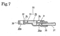
Fig. 7 is a sectional view taken on the line VII-VII inFig. 6 ; -
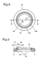
Fig. 8 is a plan view of a rubber seal; -
Fig. 9 is a sectional view taken on the line IX-IX inFig. 8 ; -
Fig. 10 is a front elevation of a thermostat; -
Fig. 11 is a side elevation of the thermostat shown inFig. 10 ; -
Fig. 12 is a top view of the thermostat shown inFig. 10 ; -
Fig. 13 is a bottom view of the thermostat shown inFig. 10 ; -
Fig. 14 is a sectional view taken on the line XIV-XIV inFig. 11 ; -
Fig. 15 is an enlarged sectional view of the thermostat mounting structure in a state where the temperature of the coolant is low; -
Fig. 16 is an enlarged sectional view of the thermostat mounting structure in a state where the temperature of the coolant is high; and -
Fig. 17 is a sectional view of a prior art thermostat mounting structure. - A thermostat mounting structure in a preferred embodiment of the present invention will be described with reference to
Figs. 1 to 16 . The thermostat mounting structure holds athermostat 50 included in the cooling system of an internal combustion engine. - Referring to
Fig. 1 , acamshaft 2 is supported for rotation on acylinder head 1. A timing chain 4 is extended between a drivensprocket 3 fixedly mounted on one end of thecam shaft 2 and a drive sprocket mounted on a crankshaft, not shown, to drive thecamshaft 2 for rotation at a rotational speed half that of the crankshaft. - The timing chain 4 is extended in a chain chamber 1a formed in the
cylinder head 1. An opening is formed coaxially with thecamshaft 2 in a side wall 1a defining the chain chamber 1a. Awater pump 5 has apump case 6 fitted in the opening of the side wall. - The
pump case 6 of thewater pump 5 has a bottomedcylindrical part 6a housing a driven magnet 8 supported on arotational shaft 7, and an enlargedpart 6b put on therotational shaft 7 and housing an impeller 9. Therotational shaft 7 has one end rotatably supported on athermostat casing 20 serving also as a pump cover. The driven magnet 8 and the impeller 9 rotate together with therotational shaft 7. - A
drive magnet 11 is fitted in acylindrical support member 10 fastened together with the drivensprocket 3 to thecamshaft 2 so as to surround thepump case 6 fitted in the chain chamber 1a of thecylinder head 1. Thedrive magnet 11 that rotates together with thecamshaft 2 entrains the driven magnet 8 of thewater ump 5 separated therefrom by thepump case 6 to rotate the impeller 9. - The
thermostat casing 20 serving also as a pump cover has an innerannular wall 22. Theannular wall 22 is fitted in theenlarged part 6b of thepump case 6 to form ascroll chamber 21 in which the impeller 9 rotates. Ajournal 23 of therotational shaft 7 extends into thethermostat casing 20 as shown inFigs. 1 and3 . - Referring to
Figs. 2 to 4 , thethermostat casing 20 serving also as a thermostat casing has an outer joiningsurface 24 to which athermostat cover 30 is joined. Athermostat chamber 25, i.e., a thermostat receiving chamber, is formed in thethermostat casing 20 so as to open in theouter contact surface 24. Athermostat 50 is fitted in thethermostat chamber 25. Threadedholes 24a are formed in the outer joiningsurface 24 at positions substantially on the opposite sides, respectively, of thethermostat chamber 25. - The
thermostat chamber 25 is defined by a taperedcircumferential surface 25a slightly tapered toward its inner end, and a substantially semisphericalbottom surface 25b. Agroove 25c of a predetermined length is formed in the taperedcircumferential surface 25a so as to extend from the open end of the taperedside surface 25a. - An
inlet coolant passage 26 is formed so as to extend perpendicularly to thethermostat chamber 25 and to open in an inner end part of thethermostat chamber 25. An upstream part of theinlet coolant passage 26 extends in aninlet connecting pipe 27, while a downstream part of theinlet coolant passage 26 is connected to anannular inlet passage 26a. Thethermostat chamber 25 extends across theinlet coolant passage 26. - An
outlet coolant passage 29 is formed in anoutlet connecting pipe 28 parallel to theinlet connecting pipe 27 as shown inFig. 4 . Theinlet coolant passage 29 is connected to thescroll chamber 21 surrounding the impeller 9. - Referring to
Figs. 10 to 14 , thethermostat 50 received in thethermostat chamber 25 of thethermostat casing 20 has a slightly tapered,cylindrical valve body 51. Thevalve body 51 is provided with a rectangular inlet opening 52 and a rectangular outlet opening 53 in substantially diametrically opposite parts thereof, and abypass opening 54 in a part below theoutlet opening 53. - The
valve body 51 has an outer open end having anannular end surface 51a, and an inner end defined by abottom wall 51b. A reduced bottomedcylindrical part 55 protrudes from thebottom wall 51b. The outer edge of theannular end surface 51a is chamfered in abevel surface 51c. -
Ribs 56 are extended along the bottomedcylindrical part 55 to thebottom wall 51b. Inner end parts of theribs 56 are rounded in a shape corresponding to the substantially semisphericalbottom surface 25b so as to merge into the circumference of thevalve body 51. - The bottomed
cylindrical part 55 and theribs 56 are formed integrally with thevalve body 51. Theribs 56 are formed in parts between theinlet opening 52 and the outlet opening 53 of thevalve body 51 so as to be contained in a plane including the center axis of thevalve body 51. - A
groove 57 is formed along the intersection of the plane including the center axis of thevalve body 51 and containing the ridges of theribs 56, and the end surfaces of theribs 56, the end surface of the bottomedcylindrical part 55, the outer circumference of thevalve body 51 and theannular end surface 51a. Arubber O ring 58 is fitted in thegroove 57. A jutting part of theO ring 58 jutting out from thegroove 57 divides a space around the outer circumference of thevalve body 51 into halves, i.e., an inlet part on the side of theinlet opening 52, and an outlet part on the side of theoutlet opening 53. - A
ridge 59 is formed on the outer circumference of thevalve body 51 at a position below thebypass opening 54 and near theannular end surface 51a. - As best shown in
Fig. 14 , avalve element 61 is fitted slidably in acylindrical space 60 in thevalve body 51 with an inner, reducedtubular part 61a thereof slidably fitted in the bottomedcylindrical part 55. An outer part of thevalve element 61 opposite thetubular part 61a is hollowed to form a space communicating with the space in thetubular part 61a. - A
diaphragm 63 is held between a step formed in the space in the outer part of thevalve element 61 and a bottomedwax case 62. An edge part of the open inner end of thewax case 62 fastened to thevalve body 61 by staking or the like. Thewax case 62 contains a wax, i.e., a thermally expandable substance. An inner part of the space in the space in thevalve body 61 on the inner side of thediaphragm 63 contains asemifluid substance 65. - A
rubber piston 66 and apiston 68 are fitted slidably in the reducedtubular part 61a with abackup plate 67 held between therubber piston 66 and thepiston 68. - A retaining
ring 69 is fitted in an annular groove formed in a part near theend surface 51a of the inner side surface of thevalve body 51. Aspring 70 is extended between the retainingring 69 and thevalve element 61 to press thevalve element 61 against thebottom wall 51b of thevalve body 51. While the coolant temperature is low, thevalve element 61 is pressed against thebottom wall 51b by thespring 70 as shown inFigs. 14 and15 , and, consequently, theinlet opening 52 and theoutlet opening 53 are closed and thebypass opening 54 is opened. - As the coolant temperature rises, the
wax 64 expands to make thediaphragm 63 bulge inward, therubber piston 66 is pushed inward, and the pressure applied to therubber piston 66 is transmitted through thebackup plate 67 to thepiston 68. Since the inner end of thepiston 68 is in contact with the bottom surface of the bottomedcylindrical part 55 and thepiston 68 is immovable, thevalve element 61 is moved outward against the resilience of thespring 70 by reaction. Consequently, theinlet opening 52 and theoutlet opening 53 are opened, and thebypass opening 54 is closed as shown inFig. 16 . - The
thermostat 50 is fitted in thethermostat chamber 25 of thethermostat casing 20 with theridge 59 formed in the outer circumference of thevalve body 51 fitted in thegroove 25c formed in the inner circumference of thethermostat chamber 25. Thus, thethermostat 50 can be positioned at a desired angular position with respect to the axis of thevalve body 51 such that theinlet passage 52 and theoutlet passage 53 correspond to theinlet coolant passage 26, and thebypass opening 54, similarly to theoutlet passage 53, corresponds to theinlet coolant passage 26. - The
O ring 58 fitted in thegroove 57 is pressed against theinner circumference 25a and thesemispherical surface 25b of thethermostat chamber 25, and divides a space between theinner circumference 25a and thevalve body 51 into halves, i.e., the inlet part on the side of theinlet opening 52, and the outlet part on the side of theoutlet opening 53, in cooperation with theribs 56 of thethermostat 50. - The thermostat cover 30 covers the open end of the
thermostat chamber 25 after fitting thethermostat 50 in thethermostat chamber 25. - Referring to
Figs. 5 to 7 , thethermostat cover 30 has a joiningsurface 31 to be joined to the joiningsurface 24 of thethermostat casing 20. An outerannular wall 32 and an innerannular wall 33 lower than and coaxial with the outerannular wall 32 are formed on the joiningsurface 31. The innerannular wall 33 surrounds arecess 35. A bypass duct 36 has abypass passage 36a extending from therecess 35. A connectingpipe 37 is press-fitted in thebypass duct 36. - The joining
surface 31 includes the end surface of the outerannular wall 32, and the respective end surfaces of mountingparts annular wall 32. The mountingparts bolt holes annular rubber seal 40, i.e. , an elastic seal, is fitted in anannular groove 34 formed between the outerannular wall 32 and the innerannular wall 33. - Referring to
Figs. 8 and 9 , therubber seal 40 has anannular body 41 having a rectangular cross section, anannular lip 42 radially inwardly protruding from the joint of theinner sealing surface 41a and the inner circumference 41b of theannular body 41, and anannular ridge 43 axially protruding away from theinner sealing surface 41a of theannular body 41. The sealingsurface 42a of thecircular lip 42, and an innerinclined surface 44a of theannular ridge 43 define anannular shoulder 44 having an L-shaped corner. Therubber seal 40 is fitted in theannular groove 34 of thethermostat cover 30. Thecircular lip 42 of therubber seal 40 rests on the end surface of the innerannular wall 33. - The joining
surface 31 of thethermostat cover 30 provided with therubber seal 40 is joined to the joiningsurface 24 of thethermostat casing 20, theinner sealing surface 41a of therubber seal 40 is joined to the joiningsurface 24 surrounding the open end of thethermostat chamber 25, theannular lip 42 of therubber seal 40 is joined to the outer end surface 21a of thevalve body 21 of thethermostat 50, and the outerinclined surface 44a of therubber seal 40 is joined to thebevel surface 51c of thevalve body 21. - When the
thermostat cover 30 is joined to thethermostat casing 20 so as to cover thethermostat chamber 25 containing thethermostat 50, therubber seal 40 is pressed against the joiningsurface 24 around the open end of thethermostat chamber 25, and the end surface 21a of thevalve body 21 of thethermostat 50 to seal thecylindrical space 60 of thevalve body 21 from the external space. - When the
thermostat cover 30 is thus attached to thethermostat casing 20, theinclined surface 44a defining the side surface of theannular shoulder 44 of therubber seal 40 comes into contact with thebevel surface 51c of the open outer end of thevalve body 21 to position thevalve body 21 easily. Theinclined surface 44a of therubber seal 40 is pressed against thebevel surface 51c of the outer open end of thevalve body 21, thevalve body 21 can be accurately and surely positioned, thevalve body 21 is restrained from displacement, and thevalve body 21 can be satisfactorily sealed. - When the
rubber seal 40 is thus compressed between the bottom surface of the annular groove 34 (and the end surface of the inner annular wall 33), and the thermostat casing 20 (and the valve body 41), the sealingsurface 41a of theannular body 41, theinclined surface 44a, and the sealingsurface 42a of thecircular lip 42 are pressed against the joiningsurface 24 of thethermostat casing 20, thebevel surface 51c of the open end of thevalve body 21, and theannular end surface 51a of thevalve body 21, respectively, to seal thethermostat 50 perfectly in thethermostat chamber 25. - The
thermostat cover 30 is fastened to thethermostat casing 20 by passing twobolts 80 through the bolt holes 38a and 39a of thethermostat cover 30 and screwing the bolts in the threadedholes 24a of thethermostat casing 20 to seal thethermostat 50 in thethermostat casing 20. - The
O ring 58 put on thevalve body 51 is pressed against theinner circumference 25a and the semi-sphericalbottom surface 25b of thethermostat chamber 25, and is held between the outer end surface 21a of thevalve body 21 and therubber seal 40. The O ring divides the space between theinner circumference 25a of thethermostat chamber 25 and thevalve body 51 into the inlet part on the side of theinlet opening 52, and the outlet part on the side of theoutlet opening 53, and seals the inlet and the outlet part. - Referring to
Fig. 1 , the coolant pumped by thewater pump 5 flows into and through an internal combustion engine E, flows into and through a radiator R, and flows through theinlet coolant passage 26 of thethermostat casing 20 to the inlet opening 52 of thethermostat 50. Part of the coolant flows through the bypass passage 37a into thecylindrical space 60 of thethermostat 50. - The low-temperature coolant circulates through the cooling system in a warm-up period subsequent to the start of the internal combustion engine E. In this warm-up period, the low-temperature coolant does not heat the
wax 64 of thethermostat 50 through thevalve element 61 of thevalve element 61 and thewax case 62. Consequently, thevalve element 61 closes theinlet opening 52 and theoutlet opening 53 and opens thebypass opening 54 as shown inFigs. 1 and15 . - Therefore, the coolant pumped by the
water pump 5 and circulated through and warmed by the internal combustion engine E flows through a bypass passage including the bypass passage 37a, thecylindrical space 60 of thethermostat 50, and thebypass opening 54 into thewater pump 5 as shown inFig. 15 . Thus, the coolant does not flow through the radiator R and circulates only through the internal combustion engine E to warm up the internal combustion engine E quickly. - Then, the temperature of the circulating coolant increases with time, the
wax 64 contained in thewax case 62 of thethermostat 50 is caused to expand by heat, and the volume of thewax 64 increases, forcing on thepiston 68 to urge the piston to project from the reducedtubular part 61a, and thepiston 68 exerts a reaction on thevalve element 61 to move thevalve element 61 against the resilience of thespring 70. Consequently, theinlet opening 52 and theoutlet opening 53 are opened and thebypass opening 54 is closed. - While the internal combustion engine is in its normal operation, the coolant pumped by the
water pump 5 and circulated through and warmed by the internal combustion engine E flows through the radiator R, and the coolant is cooled while the same is flowing through the radiator R. The cooled coolant flows through a circulation passage including theinlet opening 52, theoutlet opening 53 and thewater pump 5 to cool the internal combustion engine E. - In some cases, the cooled coolant that has flowed through the radiator R leaks from outside the
valve body 51 into thecylindrical space 60, and is mixed in the coolant circulating through the internal combustion engine E while the internal combustion engine E is in warm-up operation and the bypass circuit including thebypass passage 36a for circulating the coolant only through the internal combustion engine E is formed to impede the increase of the temperature of the coolant and to delay the warm up of the internal combustion engine, unless therubber seal 40 of thethermostat 50 exercises its sealing function perfectly. In the thermostat mounting structure embodying the present invention, the annular recess of therubber seal 40 positions thevalve body 21 accurately and surely, and therubber seal 40 exercises its high sealing function. Consequently, the leakage of the coolant flowed through the radiator R into the coolant circuit including the internal combustion engine E can be substantially perfectly prevented to avoid the extension of warming-up period.
Claims (6)
- A thermostat mounting structure wherein:a thermostat chamber (25) is provided in a casing (20) so as to extend across an inlet coolant passage (26) formed through the casing (20);a thermostat (50) is fitted in the thermostat chamber (25) of the casing (20), said thermostat (50) including a cylindrical valve body (51) having an inlet opening (52) and an outlet opening (53) in a side wall thereof, and a valve element (61) slidably fitted in the valve body (51) to open and close the inlet opening (52) and the outlet opening (53);a cover (30) is attached to the casing (20) so as to close the thermostat chamber (25), said cover (30) having an annular groove (34) in a joining surface thereof facing the thermostat (50); andan annular elastic seal (40) is fitted in the annular groove (34) of the cover (30) to seal the thermostat chamber (25) and to hold the thermostat (50) fixedly in place in the thermostat chamber (25):wherein the elastic seal (40) has an inner, corner part defined by an annular lip (42) and an annular ridge (43), and the annular lip (42) and the annular ridge (43) are pressed against an annular circumferential end portion (51a, 51c) of the valve body (51) to position the thermostat (50),wherein the annular lip (42) of the elastic seal (40) extends radially inward from a body (41) of the elastic seal (40), and the annular ridge (43) rises toward the thermostat (50) from the inner surface of the body (41) of the elastic seal (40) facing the thermostat (50).
- The thermostat mounting structure according to claim 1, wherein the elastic seal (40) is provided with an annular shoulder (44) having an L-shaped cross section in the inner corner part defined by the annular lip (42) and the annular ridge (43), and the annular circumferential end portion (51a,51c) of the outer end of the valve body (51) are fitted against the annular shoulder (44) to position the thermostat (50).
- The thermostat mounting structure according to claim 2, wherein the annular ridge (43) defining the annular shoulder (44) of the elastic seal (40) has an inclined inner side surface (44a), and the outer edge of the end surface of the valve body (51) in contact with the inclined inner side surface (44a) of the annular ridge (43) is chambered in a bevel surface (51c) .
- The thermostat mounting structure according to claim 1, wherein an axial groove (25c) is formed in the side wall of the thermostat chamber (25), an axial ridge (59) is formed on the outer circumference of the valve body (51), and the thermostat (50) is fitted in the thermostat chamber (25) with the axial ridge (59) fitted in the axial groove (25c) to position the valve body (51) with respect to a circumferential direction.
- The thermostat mounting structure according to claim 1, wherein the thermostat chamber (25) of the casing (20) has an outer open end covered with the cover (30) and a substantially semispherical inner bottom (25c), and the cylindrical valve body (51) has an inner, bottomed cylindrical part (55) having an end seated on the semispherical inner bottom (25c) of the thermostat chamber (25).
- The thermostat mounting structure according to claim 5, wherein the inner, bottomed cylindrical part (55) has an outside diameter smaller than that of the valve body (51), ribs (56) are formed integrally with the inner, bottomed cylindrical end part (55) so as to extend in diametrically opposite directions, and the ribs (56) are pressed against the substantially semispherical bottom (25c).
Applications Claiming Priority (3)
| Application Number | Priority Date | Filing Date | Title |
|---|---|---|---|
| JP2003065548 | 2003-03-11 | ||
| JP2003065548A JP4212388B2 (en) | 2003-03-11 | 2003-03-11 | Thermostat mounting structure |
| PCT/JP2004/002483 WO2004081354A1 (en) | 2003-03-11 | 2004-03-01 | Mounting structure of thermostat |
Publications (3)
| Publication Number | Publication Date |
|---|---|
| EP1602809A1 EP1602809A1 (en) | 2005-12-07 |
| EP1602809A4 EP1602809A4 (en) | 2008-07-16 |
| EP1602809B1 true EP1602809B1 (en) | 2012-06-13 |
Family
ID=32984499
Family Applications (1)
| Application Number | Title | Priority Date | Filing Date |
|---|---|---|---|
| EP04716007A Expired - Lifetime EP1602809B1 (en) | 2003-03-11 | 2004-03-01 | Mounting structure of thermostat |
Country Status (6)
| Country | Link |
|---|---|
| EP (1) | EP1602809B1 (en) |
| JP (1) | JP4212388B2 (en) |
| KR (1) | KR20050117527A (en) |
| CN (1) | CN100368660C (en) |
| TW (1) | TWI317778B (en) |
| WO (1) | WO2004081354A1 (en) |
Families Citing this family (7)
| Publication number | Priority date | Publication date | Assignee | Title |
|---|---|---|---|---|
| GB2444271B (en) * | 2006-11-29 | 2011-05-18 | Ford Global Tech Llc | A thermostat for an engine cooling system |
| CA2727578C (en) * | 2008-07-10 | 2016-02-09 | Nippon Thermostat Co., Ltd. | Thermostat device |
| CN105332786A (en) * | 2015-12-11 | 2016-02-17 | 重庆小康工业集团股份有限公司 | Thermostat seat for engine |
| FR3055983A1 (en) * | 2016-09-14 | 2018-03-16 | Vernet | DEVICE FOR THERMOSTATICALLY CONTROLLING A FLUID |
| CN108331656B (en) * | 2018-02-05 | 2019-08-06 | 安徽江淮汽车集团股份有限公司 | A kind of universal thermostat erection support |
| JP2022190731A (en) * | 2021-06-15 | 2022-12-27 | 日本サーモスタット株式会社 | Cover member and thermostat device with the same |
| FR3126732A1 (en) * | 2021-09-06 | 2023-03-10 | Psa Automobiles Sa | MOTOR VEHICLE DIESEL TYPE THERMAL ENGINE EQUIPPED WITH A FLUID OUTLET BOX |
Family Cites Families (8)
| Publication number | Priority date | Publication date | Assignee | Title |
|---|---|---|---|---|
| JPH0319428U (en) * | 1989-07-07 | 1991-02-26 | ||
| US5018664A (en) * | 1990-05-08 | 1991-05-28 | Caltherm Corporation | Thermostat having soft mounting structure |
| US5582138A (en) * | 1995-03-17 | 1996-12-10 | Standard-Thomson Corporation | Electronically controlled engine cooling apparatus |
| JP3582055B2 (en) * | 1999-01-27 | 2004-10-27 | 日本サーモスタット株式会社 | Mounting structure of thermostat |
| JP3284407B2 (en) * | 1999-01-27 | 2002-05-20 | 日本サーモスタット株式会社 | Cooling medium flow control method and device |
| WO2002008648A1 (en) * | 2000-07-25 | 2002-01-31 | Nippon Thermostat Co., Ltd. | Case structure of thermostat |
| JP4558901B2 (en) * | 2000-07-25 | 2010-10-06 | 日本サーモスタット株式会社 | Thermostat and mounting structure of thermostat |
| JP4408539B2 (en) * | 2000-07-25 | 2010-02-03 | 日本サーモスタット株式会社 | Thermostat case structure |
-
2003
- 2003-03-11 JP JP2003065548A patent/JP4212388B2/en not_active Expired - Fee Related
-
2004
- 2004-03-01 CN CNB2004800057682A patent/CN100368660C/en not_active Expired - Fee Related
- 2004-03-01 WO PCT/JP2004/002483 patent/WO2004081354A1/en active Application Filing
- 2004-03-01 EP EP04716007A patent/EP1602809B1/en not_active Expired - Lifetime
- 2004-03-01 KR KR1020057015874A patent/KR20050117527A/en not_active Application Discontinuation
- 2004-03-03 TW TW093105575A patent/TWI317778B/en not_active IP Right Cessation
Also Published As
| Publication number | Publication date |
|---|---|
| KR20050117527A (en) | 2005-12-14 |
| JP2004270645A (en) | 2004-09-30 |
| JP4212388B2 (en) | 2009-01-21 |
| CN1756898A (en) | 2006-04-05 |
| WO2004081354A1 (en) | 2004-09-23 |
| TW200506182A (en) | 2005-02-16 |
| EP1602809A4 (en) | 2008-07-16 |
| TWI317778B (en) | 2009-12-01 |
| EP1602809A1 (en) | 2005-12-07 |
| CN100368660C (en) | 2008-02-13 |
Similar Documents
| Publication | Publication Date | Title |
|---|---|---|
| US7445161B2 (en) | Thermostat | |
| JP4400885B2 (en) | Thermostat unit | |
| JP3284407B2 (en) | Cooling medium flow control method and device | |
| EP2538052B1 (en) | Thermostat device | |
| JP2000213352A (en) | Thermostat | |
| US8573164B2 (en) | Pump apparatus | |
| CN111479990B (en) | Cooling water control valve device and engine cooling system using the same | |
| US10626784B2 (en) | Rotary type valve device | |
| EP1602809B1 (en) | Mounting structure of thermostat | |
| US7175101B2 (en) | Thermostat mounting structure | |
| JP4368043B2 (en) | Thermostat mounting structure using seal member | |
| JP4558901B2 (en) | Thermostat and mounting structure of thermostat | |
| JP2001090620A (en) | Intake device for internal combustion engine | |
| CN112780761A (en) | Valve apparatus for vehicle | |
| EP1103703B1 (en) | Thermostat device | |
| US20230175600A1 (en) | Rotary valve device | |
| JP4223137B2 (en) | Thermostat device | |
| GB2320552A (en) | A combined bypass and thermostat assembly | |
| JP2019039498A (en) | Fluid control valve |
Legal Events
| Date | Code | Title | Description |
|---|---|---|---|
| PUAI | Public reference made under article 153(3) epc to a published international application that has entered the european phase |
Free format text: ORIGINAL CODE: 0009012 |
|
| 17P | Request for examination filed |
Effective date: 20050907 |
|
| AK | Designated contracting states |
Kind code of ref document: A1 Designated state(s): AT BE BG CH CY CZ DE DK EE ES FI FR GB GR HU IE IT LI LU MC NL PL PT RO SE SI SK TR |
|
| AX | Request for extension of the european patent |
Extension state: AL LT LV MK |
|
| DAX | Request for extension of the european patent (deleted) | ||
| RBV | Designated contracting states (corrected) |
Designated state(s): ES IT |
|
| REG | Reference to a national code |
Ref country code: DE Ref legal event code: 8566 |
|
| A4 | Supplementary search report drawn up and despatched |
Effective date: 20080617 |
|
| 17Q | First examination report despatched |
Effective date: 20090804 |
|
| GRAP | Despatch of communication of intention to grant a patent |
Free format text: ORIGINAL CODE: EPIDOSNIGR1 |
|
| GRAS | Grant fee paid |
Free format text: ORIGINAL CODE: EPIDOSNIGR3 |
|
| GRAA | (expected) grant |
Free format text: ORIGINAL CODE: 0009210 |
|
| AK | Designated contracting states |
Kind code of ref document: B1 Designated state(s): ES IT |
|
| RAP1 | Party data changed (applicant data changed or rights of an application transferred) |
Owner name: HONDA MOTOR CO., LTD. Owner name: NIPPON THERMOSTAT CO., LTD. |
|
| PLBE | No opposition filed within time limit |
Free format text: ORIGINAL CODE: 0009261 |
|
| STAA | Information on the status of an ep patent application or granted ep patent |
Free format text: STATUS: NO OPPOSITION FILED WITHIN TIME LIMIT |
|
| PG25 | Lapsed in a contracting state [announced via postgrant information from national office to epo] |
Ref country code: ES Free format text: LAPSE BECAUSE OF FAILURE TO SUBMIT A TRANSLATION OF THE DESCRIPTION OR TO PAY THE FEE WITHIN THE PRESCRIBED TIME-LIMIT Effective date: 20120924 |
|
| 26N | No opposition filed |
Effective date: 20130314 |
|
| PGFP | Annual fee paid to national office [announced via postgrant information from national office to epo] |
Ref country code: IT Payment date: 20140318 Year of fee payment: 11 |
|
| PG25 | Lapsed in a contracting state [announced via postgrant information from national office to epo] |
Ref country code: IT Free format text: LAPSE BECAUSE OF NON-PAYMENT OF DUE FEES Effective date: 20150301 |