EP1602544A1 - Hydraulic master cylinder - Google Patents
Hydraulic master cylinder Download PDFInfo
- Publication number
- EP1602544A1 EP1602544A1 EP04013225A EP04013225A EP1602544A1 EP 1602544 A1 EP1602544 A1 EP 1602544A1 EP 04013225 A EP04013225 A EP 04013225A EP 04013225 A EP04013225 A EP 04013225A EP 1602544 A1 EP1602544 A1 EP 1602544A1
- Authority
- EP
- European Patent Office
- Prior art keywords
- piston
- permanent magnet
- hydraulic cylinder
- housing
- cylinder according
- Prior art date
- Legal status (The legal status is an assumption and is not a legal conclusion. Google has not performed a legal analysis and makes no representation as to the accuracy of the status listed.)
- Granted
Links
Images


Classifications
-
- B—PERFORMING OPERATIONS; TRANSPORTING
- B60—VEHICLES IN GENERAL
- B60T—VEHICLE BRAKE CONTROL SYSTEMS OR PARTS THEREOF; BRAKE CONTROL SYSTEMS OR PARTS THEREOF, IN GENERAL; ARRANGEMENT OF BRAKING ELEMENTS ON VEHICLES IN GENERAL; PORTABLE DEVICES FOR PREVENTING UNWANTED MOVEMENT OF VEHICLES; VEHICLE MODIFICATIONS TO FACILITATE COOLING OF BRAKES
- B60T17/00—Component parts, details, or accessories of power brake systems not covered by groups B60T8/00, B60T13/00 or B60T15/00, or presenting other characteristic features
- B60T17/18—Safety devices; Monitoring
- B60T17/22—Devices for monitoring or checking brake systems; Signal devices
- B60T17/221—Procedure or apparatus for checking or keeping in a correct functioning condition of brake systems
-
- B—PERFORMING OPERATIONS; TRANSPORTING
- B60—VEHICLES IN GENERAL
- B60T—VEHICLE BRAKE CONTROL SYSTEMS OR PARTS THEREOF; BRAKE CONTROL SYSTEMS OR PARTS THEREOF, IN GENERAL; ARRANGEMENT OF BRAKING ELEMENTS ON VEHICLES IN GENERAL; PORTABLE DEVICES FOR PREVENTING UNWANTED MOVEMENT OF VEHICLES; VEHICLE MODIFICATIONS TO FACILITATE COOLING OF BRAKES
- B60T11/00—Transmitting braking action from initiating means to ultimate brake actuator without power assistance or drive or where such assistance or drive is irrelevant
- B60T11/10—Transmitting braking action from initiating means to ultimate brake actuator without power assistance or drive or where such assistance or drive is irrelevant transmitting by fluid means, e.g. hydraulic
- B60T11/16—Master control, e.g. master cylinders
- B60T11/232—Recuperation valves
-
- F—MECHANICAL ENGINEERING; LIGHTING; HEATING; WEAPONS; BLASTING
- F15—FLUID-PRESSURE ACTUATORS; HYDRAULICS OR PNEUMATICS IN GENERAL
- F15B—SYSTEMS ACTING BY MEANS OF FLUIDS IN GENERAL; FLUID-PRESSURE ACTUATORS, e.g. SERVOMOTORS; DETAILS OF FLUID-PRESSURE SYSTEMS, NOT OTHERWISE PROVIDED FOR
- F15B15/00—Fluid-actuated devices for displacing a member from one position to another; Gearing associated therewith
- F15B15/20—Other details, e.g. assembly with regulating devices
- F15B15/28—Means for indicating the position, e.g. end of stroke
- F15B15/2807—Position switches, i.e. means for sensing of discrete positions only, e.g. limit switches
-
- F—MECHANICAL ENGINEERING; LIGHTING; HEATING; WEAPONS; BLASTING
- F15—FLUID-PRESSURE ACTUATORS; HYDRAULICS OR PNEUMATICS IN GENERAL
- F15B—SYSTEMS ACTING BY MEANS OF FLUIDS IN GENERAL; FLUID-PRESSURE ACTUATORS, e.g. SERVOMOTORS; DETAILS OF FLUID-PRESSURE SYSTEMS, NOT OTHERWISE PROVIDED FOR
- F15B7/00—Systems in which the movement produced is definitely related to the output of a volumetric pump; Telemotors
- F15B7/06—Details
- F15B7/08—Input units; Master units
-
- F—MECHANICAL ENGINEERING; LIGHTING; HEATING; WEAPONS; BLASTING
- F16—ENGINEERING ELEMENTS AND UNITS; GENERAL MEASURES FOR PRODUCING AND MAINTAINING EFFECTIVE FUNCTIONING OF MACHINES OR INSTALLATIONS; THERMAL INSULATION IN GENERAL
- F16D—COUPLINGS FOR TRANSMITTING ROTATION; CLUTCHES; BRAKES
- F16D25/00—Fluid-actuated clutches
- F16D25/08—Fluid-actuated clutches with fluid-actuated member not rotating with a clutching member
-
- F—MECHANICAL ENGINEERING; LIGHTING; HEATING; WEAPONS; BLASTING
- F16—ENGINEERING ELEMENTS AND UNITS; GENERAL MEASURES FOR PRODUCING AND MAINTAINING EFFECTIVE FUNCTIONING OF MACHINES OR INSTALLATIONS; THERMAL INSULATION IN GENERAL
- F16D—COUPLINGS FOR TRANSMITTING ROTATION; CLUTCHES; BRAKES
- F16D25/00—Fluid-actuated clutches
- F16D25/12—Details not specific to one of the before-mentioned types
- F16D25/126—Details not specific to one of the before-mentioned types adjustment for wear or play
-
- F—MECHANICAL ENGINEERING; LIGHTING; HEATING; WEAPONS; BLASTING
- F16—ENGINEERING ELEMENTS AND UNITS; GENERAL MEASURES FOR PRODUCING AND MAINTAINING EFFECTIVE FUNCTIONING OF MACHINES OR INSTALLATIONS; THERMAL INSULATION IN GENERAL
- F16D—COUPLINGS FOR TRANSMITTING ROTATION; CLUTCHES; BRAKES
- F16D25/00—Fluid-actuated clutches
- F16D25/08—Fluid-actuated clutches with fluid-actuated member not rotating with a clutching member
- F16D2025/081—Hydraulic devices that initiate movement of pistons in slave cylinders for actuating clutches, i.e. master cylinders
-
- F—MECHANICAL ENGINEERING; LIGHTING; HEATING; WEAPONS; BLASTING
- F16—ENGINEERING ELEMENTS AND UNITS; GENERAL MEASURES FOR PRODUCING AND MAINTAINING EFFECTIVE FUNCTIONING OF MACHINES OR INSTALLATIONS; THERMAL INSULATION IN GENERAL
- F16D—COUPLINGS FOR TRANSMITTING ROTATION; CLUTCHES; BRAKES
- F16D48/00—External control of clutches
- F16D48/02—Control by fluid pressure
- F16D2048/0212—Details of pistons for master or slave cylinders especially adapted for fluid control
-
- F—MECHANICAL ENGINEERING; LIGHTING; HEATING; WEAPONS; BLASTING
- F16—ENGINEERING ELEMENTS AND UNITS; GENERAL MEASURES FOR PRODUCING AND MAINTAINING EFFECTIVE FUNCTIONING OF MACHINES OR INSTALLATIONS; THERMAL INSULATION IN GENERAL
- F16D—COUPLINGS FOR TRANSMITTING ROTATION; CLUTCHES; BRAKES
- F16D2300/00—Special features for couplings or clutches
- F16D2300/18—Sensors; Details or arrangements thereof
Definitions
- the invention relates to a hydraulic cylinder, in particular a master cylinder, according to the preamble of claim 1.
- Such a hydraulic cylinder, piston-cylinder unit is for example from the DE 199 15 832 A1 discloses and serves, for example, the actuation of a hydraulic Clutch or brake device.
- the piston-cylinder unit that is in this Example represents a master cylinder is via the brake or clutch pedal, which is in communication with the piston rod of the cylinder, activated.
- the im Master cylinder generated hydraulic pressure is filled via a hydraulic fluid Transfer line system to a slave cylinder, which there is a shift a working piston causes and thus, for. operate a clutch release can.
- said piston-cylinder unit has a sensor system which detects the position of the piston inside the cylinder serves.
- an open to the cylinder inner wall on the outer circumference of the piston Formed annular groove on which an annular permanent magnet is arranged which is axially displaceable with the piston along the inner wall of the cylinder.
- a receiving part On the outer wall of the cylinder housing, a receiving part is fixed, in which two Hall switches are arranged, the axial distance of an initial and an end position corresponds to the piston and which is located on the magnetic field of the piston Address permanent magnet and when passing the permanent magnet trigger a switching process or an electrical signal.
- the receiving part has an electrical Terminal contact portion.
- the Hall switch only are arranged at a circumferential position, while the permanent magnet is designed rotationally symmetrical, which is usually due to the free rotation of the Piston is designed around its longitudinal axis so that the piston in each rotational position can generate a signal.
- the invention has the object based, a hydraulic cylinder with an improved and cheaper Propose sensor system.
- the invention is based on the consideration that in one of the prior art known hydraulic cylinder with a sensor system of the permanent magnet only therefore ring-shaped and arranged symmetrically to the central axis of the piston is because the pistons rotate substantially freely about this central axis can. Furthermore, in order to produce a usable signal, it must be in every rotational position the piston of the arranged on this magnet in the detection range of or more on the outside of the cylinder housing at a certain, fixed Circumferential position mounted sensors are located.
- the permanent magnet asymmetric and rotatably mounted on the piston, so the magnet can be many times more compact, i.e. be dimensioned much smaller.
- the sensor system In particular, the sensor can be reduced in size.
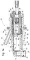
- FIG. 1a shows an axial sectional view of a hydraulic cylinder according to the invention 10 with a tracking device, which serves as a master cylinder for a hydraulic Actuating device is designed for actuating a motor vehicle clutch.
- the master cylinder 10 has a plastic housing 12 and, in a stepped bore arranged, fixedly connected to the housing 12 guide tube 14, which a common sleeve 16 for an axially movable in the cylinder 10 Plastic piston 18 with a tread 20 form.
- the housing 12 comprises at the end face a fluid connection 22 with a fluid channel 24, which via a connectable there fluid line with a drawing, not shown Slave cylinder is in fluid communication.
- the piston 18 of the master cylinder 10 is about a pivotally mounted on this piston rod 26 with a clutch pedal, not shown, in operative connection, during its actuation the piston 26 shifts to the left in the figure and via the fluid connection the slave cylinder and an associated with this clutch fork to disengage the vehicle clutch controls.
- a caster connection 28 From the lateral surface of the housing is a caster connection 28 from which with a therein run-off channel 30 with a fluid supply reservoir, not shown communicated.
- variable pressure space 32 which faces the movable piston 18 sealed against the environment.
- These are two on the housing 12, by a Intermediate ring 34 spaced annular lip seals 36, 38 arranged, each with a sealing lip on the housing 12 and with a second sealing lip on the tread 20 of the piston 18 abut.
- first seal primary seal 36
- second seal 38 serves the tight separation of the wake 42 from the atmosphere.
- the secondary seal 28 are also arranged in the housing.
- the master cylinder 10 has a tracking device 44 on.
- follower 46 in Form of an extending from the front side in the axial direction open Balancing or follower grooves arranged.
- the extension is chosen so that the Primary seal 36 is bridged in the illustrated end position of the piston 18 and a compensation channel 48 from the pressure chamber 32, starting via the follower groove 46th is released to the trailing edge 42 and on to the trailing channel 30.
- the fluid connection between the trailing region 42 and the trailing channel 30 as well the pressure chamber 32 is ensured by hidden in the figure channels in the intermediate ring 34.
- the follower groove 46 During a movement of the piston 18 in the pressure chamber 32 decreasing Direction is the follower groove 46 from the region of the primary seal 36th moved out, causing the primary seal 36 completely to the piston tread 20 applies and thus the connection between the pressure chamber 32 and the trailing channel 30 interrupts.
- the follower 46 instead of an open groove 46, the follower 46 also at the position shown as a closed groove, i. essentially as an axial bore be executed, which with a radially outwardly guided lateral Bore, i. a stitch channel is connected.
- the branch channel opens in the in Fig. 1a shown piston position immediately behind the cooperating with the piston 18 Sealing lip of the primary seal 36 in the trailing region 42nd
- the follower groove 46 on the piston 18 is on a substantially same circumferential position with respect to the housing 12 as in the trailing area 42 outflowing run-off channel 30 is arranged, so that the compensation channel 48 in the wake area 42 is as short as possible.
- the master cylinder 10 In order to maintain the mutual rotational position of the follower means, i. the compensation groove and the housing 12, the master cylinder 10 with a rotation 50 with an axial guide groove 52 in the guide tube 14 and engaging in this and axially of this guided nose 24 on the piston 18.
- an optional vent groove 60 is arranged, which a the trailing channel 30th near section 62 and the trailing channel 30 remote section 64 has.
- the trailing channel 30 remote section 64 has a relative to the horizontal by an angle ⁇ of 1.5 ° to the trailing channel 30 towards rising groove bottom 66th
- the trailing channel 30 near section 62 has a to this by the angle ⁇ , which is about 5 °, relative to the horizontal rising groove bottom 66 on and extends approximately over a third of the length of the pressure space 32.
- trailing channel 30 near section 62 forms within the pressure chamber 32 a gas bubble collection section 68 located immediately before the primary seal 36 accumulate and in the indicated position of the piston 18, in the the follower groove 46 is in the region of the primary seal 36, via the follower groove 46 and the trailing channel 30 can escape.
- the cross section corresponds to the follower groove 46 at least the cross section of the vent groove 46 in the region of the primary seal 36. This will lead to a build-up of accumulation of relatively large amounts of gas the compensation channel 46 avoided during a venting process.
- annular groove 70 may be an additional Cover element 72, for example.
- An annular disc 72 is introduced to cover the annular groove 70 be as this is shown in the detail of Fig. 1 b.
- the ring disk For this purpose, 72 is centered between the primary seal 36 and the shoulder 40 of the Housing 12 is taken, wherein the inner diameter is dimensioned so that the Running surface 20 of the piston 18 can slide past without contact.
- the hydraulic cylinder 10 st provided for installation in a horizontal position. in this connection corresponds to the central axis A of the hydraulic cylinder 10 of the horizontal.
- the hydraulic cylinder 10 can also with its connection 22 for the pressure line upwards around an angle ⁇ smaller or equal to the horizontal angle be arranged inclined.
- the piston 18 can also have a plurality of such grooves 46.
- the one or more follower grooves 46 are preferably on the piston 18 at the geodetically highest range and adjacent formed to the gas collecting section 68. In the horizontal shown in the figure Position are the Nachlaufnuten 46 in the upper half-plane of the piston 18, and particularly preferably close to the wake channel 30 and conveniently also in the range the vent groove 60 is positioned.
- one or more Austiciansnuten 46 outside of with the gas collecting portion 68 cooperating piston area are formed.
- the balance grooves 46 are to be arranged and dimensioned overall, that with a vent the effect described below can be adjusted.
- the flow rate of the fluid in the or Balancing grooves 46 set as high as possible, which in a given piston cross section by a suitable choice of the groove cross-section in conjunction with the Number of grooves can be easily done.
- a short, axially extending Bridge 74 may be formed when reaching the inserted end position the piston 18 there positively engages in the Ausretesnut 46 and in the Ausretesnut damming, but not after passing the primary seal 36 more displaced from the groove 46 on these dischargeable gas accumulations, whereupon dodge these in the vent groove 60 and in this direction of the primary seal 36 can go up to turn off at a next venting process to escape the pressure chamber 32.
- the hydraulic cylinder 10 comprises according to FIG. 1 a, a sensor system 55 for detection a piston position, wherein the piston 18, a rod-shaped permanent magnet 56 and on the outside of the housing 12 or alternatively on the guide sleeve 14, a detector unit 58 for detecting a magnetic field induced by the permanent magnet 56 are arranged.
- the detector unit 58 comprises a sensor housing 59, in which two magnetic field sensitive Sensors 61, 63, e.g. Hall sensors or reed contacts are included. alternative can also be continuously working capacitive or inductive displacement transducer be used as sensors.
- the axial positioning of the permanent magnet 56 on the piston 18 is in principle freely selectable, but is in the position shown the axial distance of the magnet 56 to the pressure chamber 32 is minimized, resulting in a constructive advantage in the positioning of the sensors 61, 63 and the sensor housing 59 results, which saves space in the front region of the cylinder housing 12th and thus directly axially in the region of the pressure chamber 32 can be formed.
- the permanent magnet 56 and the sensors 61, 63 are located substantially on the same circumferential position.
- the magnet 56 is one of its two Magnetic poles on the sensors 61, 63 aligned, so that of the there especially strong magnetic field can be applied.
- the axial distance of the sensors 61, 63 corresponds approximately to an initial and a End position of the piston 18.
- the piston 18 is indeed axially off the position of the sensor 61, but still within its detection range.
- the piston 18 in its sleeve 16 is the respectively axially closest to the permanent magnet 56 sensor 24 and 26 of the latter Detected magnetic field and can then perform a switching movement and / or generated an electrical signal, which via a signal line, not shown an evaluation is forwarded for further processing. It can too Both sensors 61, 63 simultaneously with the magnetic field of the permanent magnet 56th be acted upon, from the respective resulting signal ratio of the sensors 61, 63, the position of the piston 18 can be determined.
- the rotation can 50 alternatively be carried out under the participation itself, such as this is shown in Fig. 2.
- the magnet 56 is inserted into the piston 18, that this protrudes slightly radially beyond the piston running surface 20.
- the supernumerary Area of the magnet 56 engages in an axial groove 76 formed on the pressure chamber 32 and is held by this against rotation.
- the illustrated variant has the advantage that the nose 54 can be omitted on the piston and that the permanent magnet 56 is guided substantially closer to the detector unit 58 can be, as this is known so far. This results in the further advantage that less massive can be performed while the detector unit 58 a may have lower sensitivity.
- the permanent magnet 56 as shown in the section of FIG. 3, Also arranged on a pressure chamber 32 on the piston 18 formed axial extension 80 be.
- On the axial extension 80 is a preferably made of plastic Receiving element 82 rotatably mounted, but axially fixed.
- the receiving element 82 by means of a one-way locking device, a snap connection or a other securing means 83 on the piston 18 as axially as possible without play and insoluble be assured.
- the receiving element 82 has a radially projecting and the tread 20 of the piston 18 superior nose 84 or pin on which in an axial groove 76a can engage, which is opposite to the vent groove 60 at the pressure chamber 32 is trained.
- the magnet 56 is preferably in the receiving element 82 poured, but alternatively, other attachment methods, such as Example, the insertion, snapping or pressing into a recess as in Fig. 2, a locking connection or the like are possible.
- the free rotation of the piston remains, unless otherwise is restricted, and receive only the receiving element 82 with the Magnet 56 are secured against rotation to the housing 12 and thus to the sensors 61, 63 established.
- the material for the permanent magnet 56 is particularly well an alloy the material system iron neodymium-boron (FeNdB), with a particularly high magnetic flux density can be displayed.
- FeNdB iron neodymium-boron
- a surface corrosion protection layer For example, a nickel coating.
- the detector unit 58 Due to the asymmetrical arrangement of the permanent magnet 56, the detector unit 58 overall very compact and cost-effective and a significant Amount of costly magnetic material can be saved.
Abstract
Description
Die Erfindung betrifft einen Hydraulikzylinder, insbesondere einen Geberzylinder, gemäß dem Oberbegriff des Patentanspruchs 1.The invention relates to a hydraulic cylinder, in particular a master cylinder, according to the preamble of claim 1.
Eine solcher Hydraulikzylinder, Kolben-Zylinder-Aggregat ist beispielsweise aus der DE 199 15 832 A1 bekannt und dient beispielsweise der Betätigung einer hydraulischen Kupplungs oder Bremsvorrichtung. Das Kolben-Zylinder-Aggregat, das in diesem Beispiel einen Geberzylinder darstellt, wird über das Brems- oder Kupplungspedal, welches mit der Kolbenstange des Zylinders in Verbindung steht, aktiviert. Der im Geberzylinder erzeugte hydraulische Druck wird über ein mit Hydraulikflüssigkeit befülltes Leitungssystem an einen Nehmerzylinder übertragen, welcher dort eine Verschiebung eines Arbeitskolbens bewirkt und damit z.B. einen Kupplungsausrücker betätigen kann. Des Weiteren weist das genannte Kolben-Zylinder-Aggregat ein Sensorsystem auf, welches der Erkennung der Stellung des Kolbens innerhalb des Zylinders dient. Dazu ist am Außenumfang des Kolbens eine zur Zylinderinnenwand offene Ringnut ausgebildet, an der ein ringförmiger Permanentmagnet angeordnet ist, welcher mit dem Kolben entlang der Innenwandung des Zylinders axial verschiebbar ist. An der Außenwandung des Zylindergehäuses ist ein Aufnahmeteil befestigt, in dem zwei Hall-Schalter angeordnet sind, deren Axialabstand einer Anfangs- und einer Endposition des Kolbens entspricht und die auf das Magnetfeld des am Kolben befindlichen Permanentmagneten ansprechen und beim Vorbeigleiten des Permanentmagneten einen Schaltvorgang bzw. ein elektrisches Signal auslösen. Zur Weitergabe des Signals an Steuer- oder Kontrollstrukturen besitzt das Aufnahmeteil ein elektrisches Anschlusskontaktteil.Such a hydraulic cylinder, piston-cylinder unit is for example from the DE 199 15 832 A1 discloses and serves, for example, the actuation of a hydraulic Clutch or brake device. The piston-cylinder unit that is in this Example represents a master cylinder is via the brake or clutch pedal, which is in communication with the piston rod of the cylinder, activated. The im Master cylinder generated hydraulic pressure is filled via a hydraulic fluid Transfer line system to a slave cylinder, which there is a shift a working piston causes and thus, for. operate a clutch release can. Furthermore, said piston-cylinder unit has a sensor system which detects the position of the piston inside the cylinder serves. For this purpose, an open to the cylinder inner wall on the outer circumference of the piston Formed annular groove on which an annular permanent magnet is arranged, which is axially displaceable with the piston along the inner wall of the cylinder. On the outer wall of the cylinder housing, a receiving part is fixed, in which two Hall switches are arranged, the axial distance of an initial and an end position corresponds to the piston and which is located on the magnetic field of the piston Address permanent magnet and when passing the permanent magnet trigger a switching process or an electrical signal. To pass on the Signal to control or control structures, the receiving part has an electrical Terminal contact portion.
Der genannten Druckschrift sind keine detaillierten Angaben darüber entnehmbar, wie der Permanentmagnet am Kolben befestigt ist. Angesichts der einzigen Figur kann jedoch davon ausgegangen werden, dass in einem ersten Arbeitsschritt der Kolben gefertigt wird und in einem weiteren Arbeitsschritt der Ringmagnet von der dem Druckraum abgewandten Seite des Kolbens in die Ringnut des Kolbens aufgeschoben wird. Dabei ist von Nachteil, dass bei diesem Zusammenbau von Kolben und Permanentmagnet auch bei größter Sorgfalt ein nachträgliches Lösen des Permanentmagneten von der Montageposition am Kolben infolge von plötzlichen, schockartigen Belastungen des Kolbens nicht ausgeschlossen werden kann und somit die Positionserkennung des Kolbens fehlerhaft erfolgen kann. Im Extremfall kann der Permanentmagnet zerbersten, was zu einer Blockierung des Kolbens und damit zum Ausfall des hydraulischen Systems führen kann. An dem Sensorsystem fällt auf, dass die Hallschalter lediglich an einer Umfangsposition angeordnet sind, währens der Permanentmagnet rotationssymmetrisch gestaltet ist, was üblicherweis wegen der freien Drehbarkeit des Kolbens um dessen Längsachse so ausgeführt ist, damit der Kolben in jeder Drehlage ein Signal erzeugen kann. The cited document are no detailed information about how to remove the permanent magnet is attached to the piston. Given the single figure can however, assume that in a first step the piston is manufactured and in a further step of the ring magnet of the Pressure chamber facing away from the piston pushed into the annular groove of the piston becomes. It is disadvantageous that in this assembly of piston and permanent magnet even with the utmost care a subsequent release of the permanent magnet from the mounting position on the piston due to sudden, shock loads the piston can not be excluded and thus the position detection the piston can be faulty. In extreme cases, the permanent magnet burst, resulting in a blockage of the piston and thus failure of the hydraulic Systems can lead. On the sensor system is noticeable that the Hall switch only are arranged at a circumferential position, while the permanent magnet is designed rotationally symmetrical, which is usually due to the free rotation of the Piston is designed around its longitudinal axis so that the piston in each rotational position can generate a signal.
Von dem genannten Stand der Technik ausgehend, liegt der Erfindung die Aufgabe zugrunde, einen Hydraulikzylinder mit einem verbesserten und kostengünstigeren Sensorsystem vorzuschlagen.Starting from the cited prior art, the invention has the object based, a hydraulic cylinder with an improved and cheaper Propose sensor system.
Die vorstehend genannte Aufgabe wird durch einen gattungsgemäßen Hydraulikzylinder mit den im Kennzeichen des Patentanspruchs 1 angegebenen Merkmale gelöst. Vorteilhafte Weiterbildungen und Ausgestaltungen der Erfindung sind in den Unteransprüchen angegeben.The above object is achieved by a generic hydraulic cylinder solved with the features specified in the characterizing part of claim 1. Advantageous developments and refinements of the invention are in the dependent claims specified.
Die Erfindung geht von der Überlegung aus, dass bei einem aus dem Stand der Technik bekannten Hydraulikzylinder mit einem Sensorsystem der Permantmagnet nur deswegen ringförmig ausgebildet und symmetrisch zur Mittelachse des Kolbens angeordnet ist, weil sich der Kolben im Wesentlichen frei um diese Mittelachse drehen kann. Des Weiteren muss sich, um ein verwertbares Signal zu erzeugen, in jeder Drehlage des Kolbens der an diesem angeordnete Magnet im Erfassungsbereich eines oder mehrerer an der Außenseite des Zylindergehäuses an einer bestimmten, festen Umfangsposition angebrachten Sensoren befinden.The invention is based on the consideration that in one of the prior art known hydraulic cylinder with a sensor system of the permanent magnet only therefore ring-shaped and arranged symmetrically to the central axis of the piston is because the pistons rotate substantially freely about this central axis can. Furthermore, in order to produce a usable signal, it must be in every rotational position the piston of the arranged on this magnet in the detection range of or more on the outside of the cylinder housing at a certain, fixed Circumferential position mounted sensors are located.
Wird, so wie es die Erfindung vorschlägt, der Permanentmagnet asymmetrisch und drehfest am Kolben angeordnet, so kann der Magnet um ein Mehrfaches kompakter, d.h. wesentlich kleiner dimensioniert werden. Gleichfalls kann auch das Sensorsystem, insbesondere der Sensor in dessen Baugröße verkleinert werden. Is, as proposed by the invention, the permanent magnet asymmetric and rotatably mounted on the piston, so the magnet can be many times more compact, i.e. be dimensioned much smaller. Likewise, the sensor system, In particular, the sensor can be reduced in size.
Die Erfindung wird nachfolgend unter Bezugnahme auf die beigefügten Figuren anhand eines bevorzugten Ausführungsbeispiels an einem Geberzylinder für eine Kraftfahrzeugkupplung erläutert. Es zeigen:
- Fig. 1 a
- eine Axialschnittdarstellung eines Hydraulikzylinders mit einer Nachlaufeinrichtung,
- Fig. 1 b
- ein Ausschnitt des Hydraulikzylinders der Fig. 1 a mit einer im Bereich der Primärdichtung angeordneten Ringscheibe,
- Fig.2
- eine schematische Darstellung der Anordnung eines Permanentmagneten an einem Kolben eines Hydraulikzyklinders in einem Radialschnitt,
- Fig. 3
- eine weitere Anordnungsvariante eines Permanentmagneten an einem Kolben.
- Fig. 1 a
- an axial sectional view of a hydraulic cylinder with a tracking device,
- Fig. 1 b
- 1 a with a ring disk arranged in the region of the primary seal,
- Fig.2
- a schematic representation of the arrangement of a permanent magnet on a piston of a Hydraulikzyklinders in a radial section,
- Fig. 3
- a further arrangement variant of a permanent magnet on a piston.
Die Fig.1a zeigt eine Axialschnittdarstellung eines erfindungsgemäßen Hydraulikzylinders
10 mit einer Nachlaufeinrichtung, welcher als Geberzylinder für eine hydraulische
Betätigungseinrichtung zur Betätigung einer Kraftfahrzeugkupplung ausgebildet ist.
Der Geberzylinder 10 weist ein Kunststoff-Gehäuse 12 und ein, in einer Stufenbohrung
angeordnetes, fest mit dem Gehäuse 12 verbundenes Führungsrohr 14 auf, welche
eine gemeinsame Laufbuchse 16 für einen in dem Zylinder 10 axial beweglichen
Kunststoff-Kolben 18 mit einer Lauffläche 20 bilden.1a shows an axial sectional view of a hydraulic cylinder according to the
Das Gehäuse 12 umfasst an der Stirnseite einen Fluidanschluss 22 mit einem Fluidkanal
24, der über eine dort verbindbare Fluidleitung mit einem zeichnerisch nicht dargestellten
Nehmerzylinder in Fluidverbindung steht. Der Kolben 18 des Geberzylinders
10 steht über eine schwenkbeweglich an diesem angeordnete Kolbenstange 26 mit
einem nicht dargestellten Kupplungspedal in Wirkverbindung, bei dessen Betätigung
sich der Kolben 26 in der Figur nach links verschiebt und über die Fluidverbindung
den Nehmerzylinder und eine mit diesen verbundene Kupplungsgabel zum Ausrücken
der Fahrzeugkupplung steuert.The
Von der Mantelfläche des Gehäuses steht ein Nachlaufanschluss 28 ab, der mit einem
darin ausgeführten Nachlaufkanal 30 mit einem nicht dargestellten Fluid-Nachlaufbehälter
kommuniziert.From the lateral surface of the housing is a
Die Stirnseite des Kolbens 18 und die Innenwandung des Zylindergehäuses 12 definieren
einen variablen Druckraum 32, welcher gegenüber dem beweglichen Kolben
18 gegen die Umgebung abgedichtet ist. Dazu sind am Gehäuse 12 zwei, durch einen
Zwischenring 34 beabstandete Ringlippendichtungen 36, 38 angeordnet, die jeweils
mit einer Dichtlippe am Gehäuse 12 und mit einer zweiten Dichtlippe an der Lauffläche
20 des Kolbens 18 anliegen. Die axial zwischen dem Nachlaufkanal 30 und dem
Druckraum 32, an einem Gehäuseabsatz 40 anliegende erste Dichtung (Primärdichtung
36) dichtet den Druckraum 32 gegenüber einen durch den Zwischenring 34 gebildeten
ringförmigen Nachlaufbereich 42 ab. Die zweite, am Ende des Führungsrohres
14 befindliche Ringlippendichtung (Sekundärdichtung 38) dient der dichten Abtrennung
des Nachlaufbereichs 42 von der Atmosphäre. Alternativ kann die Sekundärdichtung
28 auch im Gehäuse angeordnet werden. Define the end face of the
Um ein Nachlaufen von Hydraulikflüssigkeit in und das Entweichen von Gasblasen aus
dem Druckraum 32 sicherzustellen, weist der Geberzylinder 10 eine Nachlaufeinrichtung
44 auf. Zu diesem Zweck sind an der Kolbenlauffläche 20 Nachlaufmittel 46 in
Form einer sich von dessen Stirnseite aus in axialer Richtung erstreckenden offenen
Ausgleichs- bzw. Nachlaufnuten angeordnet. Die Erstreckung ist so gewählt, dass die
Primärdichtung 36 in der dargestellten Endstellung des Kolbens 18 überbrückt wird
und ein Ausgleichskanal 48 vom Druckraum 32 ausgehend über die Nachlaufnut 46
zum Nachlaufbereich 42 und weiter zum Nachlaufkanal 30 freigegeben wird. Die Fluidverbindung
zwischen dem Nachlaufbereich 42 und dem Nachlaufkanal 30 sowie
dem Druckraum 32 wird durch in der Figur verdeckte Kanäle im Zwischenring 34 sichergestellt.
Bei einer Bewegung des Kolbens 18 in die den Druckraum 32 verkleinernde
Richtung wird die Nachlaufnut 46 aus dem Bereich der Primärdichtung 36
herausbewegt, wodurch sich die Primärdichtung 36 vollständig an die Kolbenlauffläche
20 anlegt und damit die Verbindung zwischen dem Druckraum 32 und dem Nachlaufkanal
30 unterbricht. Anstelle einer offen Nut 46 können die Nachlaufmittel 46
auch an der gezeigten Position als geschlossene Nut, d.h. im wesentlichen als Axialbohrung
ausgeführt werden, welche mit einer nach radial aussen geführten seitlichen
Bohrung, d.h. einem Stichkanal verbunden ist. Der Stichkanal mündet in der in Fig. 1a
gezeigten Kolbenstellung unmittelbar hinter der mit dem Kolben 18 zusammenwirkenden
Dichtlippe der Primärdichtung 36 in den Nachlaufbereich 42.To run after hydraulic fluid in and the escape of gas bubbles
To ensure the
Wie aus der Fig.1a ersichtlich, ist die Nachlaufnut 46 am Kolben 18 auf einer im Wesentlichen
gleichen Umfangslage bezüglich des Gehäuses 12 wie der in den Nachlaufbereich
42 mündende Nachlaufkanal 30 angeordnet, so dass der Ausgleichskanal
48 im Nachlaufbereich 42 möglichst kurz bemessen ist.As can be seen from Fig.1a, the
Zur Beibehaltung der gegenseitigen Drehlage der Nachlaufmittel, d.h. der Ausgleichsnut
und dem Gehäuse 12 weist der Geberzylinder 10 eine Verdrehsicherung 50 mit
einer axialen Führungsnut 52 im Führungsrohr 14 und einer in diese eingreifende und
axial von dieser geführten Nase 24 am Kolben 18 auf.In order to maintain the mutual rotational position of the follower means, i. the compensation groove
and the
In der oberen Wandung des Druckraums ist zur weiteren Unterstützung der Entlüftung
eine optionale Entlüftungsnut 60 angeordnet, welche einen dem Nachlaufkanal 30
nahen Abschnitt 62 und einen dem Nachlaufkanal 30 fernen Abschnitt 64 aufweist.
Der dem Nachlaufkanal 30 ferne Abschnitt 64 hat einen gegenüber der Horizontalen
um einen Winkel α von 1,5° zu dem Nachlaufkanal 30 hin ansteigenden Nutgrund 66.
Der dem Nachlaufkanal 30 nahe Abschnitt 62 weist einen zu diesem um den Winkel
β, der etwa 5° beträgt, gegenüber der Horizontalen ansteigenden Nutgrund 66 auf
und erstreckt sich ungefähr über ein Drittel der Länge des Druckraums 32. Insbesondere
der dem Nachlaufkanal 30 nahe Abschnitt 62 bildet innerhalb des Druckraums
32 einen Sammelabschnitt 68 für Gasblasen, welche sich unmittelbar vor der Primärdichtung
36 ansammeln und in der eingezeichneten Stellung des Kolbens 18, in der
sich die Nachlaufnut 46 im Bereich der Primärdichtung 36 befindet, über die Nachlaufnut
46 und den Nachlaufkanal 30 entweichen können.In the upper wall of the pressure chamber is to further assist the vent
an
Bei einem Unterdruck im Druckraum 32 strömt über die Nachlaufnut 46 zudem
Hydraulikfluid in diesen nach. Vorteilhafterweise entspricht der Querschnitt der Nachlaufnut
46 mindestens dem Querschnitt der Entlüftungsnut 46 im Bereich der Primärdichtung
36. Damit wird bei relativ großen Gasansammlungen eine Aufstauung an
dem Ausgleichskanal 46 bei einem Entlüftungsvorgang vermieden.At a negative pressure in the
Zur Vermeidung eines Übertritts von Restgas aus dem Druckraum 32 in die von den
Dichtlippen der Primärdichtung 36 aufgespannte Ringnut 70 kann ein zusätzliches
Deckelement 72, bspw. eine Ringscheibe 72 zur Abdeckung der Ringnut 70 eingebracht
werden, wie dieses in dem Ausschnitt der Fig. 1 b gezeigt ist. Die Ringscheibe
72 wird dazu zwischen der Primärdichtung 36 und dem Absatz 40 zentriert von dem
Gehäuse 12 aufgenommen, wobei deren Innendurchmesser so bemessen ist, dass die
Lauffläche 20 des Kolbens 18 berührungsfrei vorbeigleiten kann.To avoid a transfer of residual gas from the
Der Hydraulikzylinder 10 st zum Einbau in einer horizontalen Lage vorgesehen. Hierbei
entspricht die Mittelachse A des Hydraulikzylinders 10 der Horizontalen. Der Hydraulikzylinder
10 kann auch mit seinem Anschluß 22 für die Druckleitung nach oben hin
um einen gegenüber dem Winkel α kleineren oder gleich großen Winkel zur Horizontalen
geneigt angeordnet werden.The
Alternativ zu der Ausbildung einer einzigen Nachlaufnut 46 kann der Kolben 18 auch
mehrere derartiger Nuten 46 aufweisen. Die eine oder mehreren Nachlaufnuten 46
sind vorzugsweise am Kolben 18 am geodätisch höchsten Bereich und benachbart
zum Gassammelabschnitt 68 ausgebildet. Bei der in der Figur dargestellten horizontalen
Lage sind die Nachlaufnuten 46 in der oberen Halbebene des Kolbens 18, und
besonders bevorzugt nahe zum Nachlaufkanal 30 und günstigerweise ebenso im Bereich
der Entlüftungsnut 60 positioniert.As an alternative to the formation of a
Zusätzlich können auch eine oder mehrere Ausgleichsnuten 46 ausserhalb des mit
dem Gassammelabschnitt 68 zusammenwirkenden Kolbenbereichs ausgebildet werden.
Jedoch sind die Ausgleichsnuten 46 insgesamt so anzuordnen und zu dimensionieren,
dass sich bei einer Entlüftung die unten beschriebene Wirkung einstellen kann.In addition, one or more Ausgleichsnuten 46 outside of with
the
Bei einem Entlüftungsvorgang mit einer Kolbenbewegung in den Druckraum 32 hinein
wird beim Vorhandensein einer Gasansammlung in der Entlüftungsnut 60 oder wenn
diese nicht ausgebildet ist im geodätisch oberen Volumenbereich des Druckraumes 32
Fluid verdrängt und hat dort einen ansteigenden Fluidpegel zur Folge, da das Fluid
über die ggf. ausserhalb des Gassammelabschnittes 68 angeordneten Ausgleichsnuten
nur ungenügend schnell aus dem Druckraum entweichen kann. In Folge werden
die im Gassammelabschnitt 68 vorhandenen Gase zunächst komprimiert und anschließend
über die zu diesem unmittelbar benachbarten, d.h. in diesem Zustand in
direkter Strömungsverbindung stehenden Nachlaufmitteln 46 mit dem überschüssigen,
verdrängten Fluid aus dem Druckraum 32 geschoben bzw. herausgepresst.In a venting process with a piston movement into the
Zur Erzielung einer möglichst vollständigen Entgasung des Druckraumes 32 ist es von
besonderer Bedeutung, die Strömungsgeschwindigkeit des Fluids in der oder den
Ausgleichsnuten 46 möglichst hoch einzustellen, was bei einem vorgegebenen Kolbenquerschnitt
durch eine geeignete Wahl des Nutquerschnitts in Verbindung mit der
Nutanzahl einfach erfolgen kann. To achieve the most complete degassing of the
Am stirnseitigen Ende des Druckraums 32 kann zusätzlich ein kurzer, sich axial erstreckender
Steg 74 ausgebildet sein, der bei Erreichen der eingeschobenen Endposition
des Kolbens 18 dort formschlüssig in die Ausgleichsnut 46 eingreift und sich in der
Ausgleichsnut aufstauende, jedoch nach dem Passieren der Primärdichtung 36 nicht
mehr über diese abführbare Gasansammlungen aus der Nut 46 verdrängt, worauf sich
diese in die Entlüftungsnut 60 ausweichen und in dieser in Richtung der Primärdichtung
36 nach oben ansteigen können, um bei einem nächsten Entlüftungsvorgang aus
dem Druckraum 32 zu entweichen.At the front end of the
Der Hydraulikzylinder 10 umfasst gemäß Fig. 1 a ein Sensorsystem 55 zur Detektion
einer Kolbenstellung, wobei am Kolben 18 ein stabförmiger Permanentmagnet 56 und
an der Außenseite des Gehäuses 12 oder alternativ an der Führungshülse 14 eine Detektoreinheit
58 zur Erfassung einer von dem Permanentmagnet 56 induzierten Magnetfeldänderung
angeordnet sind.The
Die Detektoreinheit 58 umfasst ein Sensorgehäuse 59, in dem zwei magnetfeldempfindliche
Sensoren 61, 63, z.B. Hall-Sensoren oder Reed-Kontakte enthalten sind. Alternativ
können auch kontinuierlich arbeitende kapazitive oder induktive Wegaufnehmer
als Sensoren eingesetzt werden. Die axiale Positionierung des Permanentmagneten
56 am Kolben 18 ist prinzipiell frei wählbar, jedoch ist an der dargestellten Position
der axiale Abstand des Magneten 56 zum Druckraum 32 minimiert, wodurch sich ein
konstruktiver Vorteil bei der Positionierung der Sensoren 61, 63 und des Sensorgehäuses
59 ergibt, welches platzsparend im vorderen Bereich des Zylindergehäuses 12
und somit unmittelbar axial im Bereich des Druckraumes 32 ausgebildet werden kann.
Der Permanentmagnet 56 und die Sensoren 61, 63 befinden sich im Wesentlichen auf
derselben Umfangslage. Vorteilhafterweise ist der Magnet 56 mit einem seiner beiden
Magnetpole auf die Sensoren 61, 63 ausgerichtet, damit diese von dem dort besonders
stark ausgeprägten Magnetfeld beaufschlagt werden können.The
Der axiale Abstand der Sensoren 61, 63 entspricht dabei etwa einer Anfangs- und einer
Endstellung des Kolbens 18. In Fig. 1 a befindet sich der Kolben 18 zwar axial abseits
der Position des Sensors 61, jedoch noch innerhalb dessen Erfassungsbereiches.
Bei einer Axialbewegung des Kolbens 18 in dessen Laufbuchse 16 wird der jeweils
axial dem Permanentmagneten 56 nächstliegende Sensor 24 bzw. 26 von dessen
Magnetfeld erfasst und kann daraufhin eine Schaltbewegung ausführen und/oder erzeugt
ein elektrisches Signal, welches über eine nicht dargestellte Signalleitung an
eine Auswerteeinheit zur weiteren Bearbeitung weitergeleitet wird. Es können auch
beide Sensoren 61, 63 gleichzeitig mit dem Magnetfeld des Permanentmagneten 56
beaufschlagt werden, wobei aus dem jeweils resultierenden Signalverhältnis der Sensoren
61, 63 die Position des Kolbens 18 ermittelt werden kann.The axial distance of the
In den verdrehsicher in der Laufbuchse 16 geführten Kolben 18 ist, wie in der Figur zu
erkennen, asymmetrisch zur Kolben- und zur Zylindermittellinie A der Permanentmagnet
56 eingesetzt, der zumindest im Bereich der Kolbenlauffläche 20 vollständig vom
Kunststoffmaterial des Kolbens 18 umgeben ist. Somit ist der Magnet 56 einerseits
gegen Korrosionserscheinungen sicher geschützt, andererseits wird die Lauffläche 20
des Kolbens 18 nicht unterbrochen, was einen verschleißarmen, langlebigen Betrieb
des Hydraulikzylinders 10 garantiert.In the non-rotatably guided in the
Zur Anordnung des Permanentmagneten 56 im Hydraulikzylinder 10 kann die Verdrehsicherung
50 alternativ unter dessen Mitwirkung selbst ausgeführt werden, wie
dieses in Fig. 2 dargestellt ist. Dazu ist der Magnet 56 so in den Kolben 18 eingesetzt,
dass dieser radial etwas über die Kolbenlauffläche 20 heraussteht. Der überstehende
Bereich des Magneten 56 greift in eine am Druckraum 32 ausgebildete Axialnut 76 ein
und wird von dieser verdrehsicher gehalten. Beispielsweise genügt es, an der Lauffläche
20 eine Ausnehmung 78 als Aufnahmebereich vorzusehen und einen scheibenförmigen
Permanentmagneten 56 in diese einzusetzen. Da dieser in der Nut 76 geführt
wird, ist im montierten Zustand des Zylinders 10 gleichzeitig eine verliersichere
Anordnung gegeben, d.h. der Permanetmagnet 56 braucht in der Ausnehmung 78 nur
zum Zweck seiner Montage fixiert werden. Jedoch sollte ein Axialspiel zwischen dem
Magnet 56 und dessen Aufnahmebereich 78 vermieden werden, da dieses einer exakten
Stellungsdetektion des Kolbens 18 entgegensteht.For the arrangement of the
Die erläuterte Variante hat den Vorteil, dass die Nase 54 am Kolben entfallen kann und
dass der Permanentmagnet 56 wesentlich näher an der Detektoreinheit 58 geführt
werden kann, als dieses bisher bekannt ist. Daraus ergibt sich der weitere Vorteil, dass
weniger massiv ausgeführt werden kann und gleichzeitig die Detektoreinheit 58 eine
geringere Ansprechempfindlichkeit aufweisen kann. The illustrated variant has the advantage that the
Alternativ kann der Permanentmagnet 56, wie in dem Ausschnitt der Fig. 3 dargestellt,
auch an einem zum Druckraum 32 am Kolben 18 ausgebildeten Axialfortsatz 80 angeordnet
sein. Auf dem Axialfortsatz 80 ist ein vorzugsweise aus Kunststoff gefertigtes
Aufnahmeelement 82 drehfrei, jedoch axial fixiert gelagert. Dazu kann das Aufnahmelement
82 mittels einer Einweg-Rastvorrichtung, einer Schnappverbindung oder eines
anderen Sicherungsmittels 83 am Kolben 18 axial möglichst spielfrei und unlösbar
gesichert sein. Das Aufnahmeelement 82 weist eine radial abstehende und die Lauffläche
20 des Kolbens 18 überragende Nase 84 bzw. Zapfen auf, die in eine Axialnut
76a eingreifen kann, welche zu der Entlüftungsnut 60 am Druckraum 32 gegenüberliegend
ausgebildet ist. Der Magnet 56 ist vorzugsweise in das Aufnahmelement
82 eingegossen, wobei alternativ auch andere Befestigungsmethoden, wie zum
Beispiel das Einlassen, Einschnappen oder Einpressen in eine Ausnehmung wie in
Fig. 2 gezeigt, eine Rastverbindung oder ähnliches möglich sind.Alternatively, the
Bei dieser Variante bleibt die freie Drehbarkeit des Kolbens, sofern diese nicht anderweitig
eingeschränkt ist, erhalten und lediglich das Aufnahmeelement 82 mit dem
Magnet 56 sind verdrehgesichert zum Gehäuse 12 und damit zu den Sensoren 61, 63
festgelegt.In this variant, the free rotation of the piston remains, unless otherwise
is restricted, and receive only the receiving
Als Werkstoff für den Permanentmagneten 56 eignet sich besonders gut eine Legierung
des Materialsystems Eisen-Neodym-Bor (FeNdB), mit der eine besonders hohe
magnetische Flußdichte darstellbar ist. Befindet sich der Magnetwerkstoff mit dem
Fluid in unmittelbaren Kontakt, so empfiehlt sich das Aufbringen einer Oberflächenkorrosionsschutzschicht,
bspw. eines Nickelüberzugs. As the material for the
Durch die asymmetrische Anordnung des Permanentmagneten 56 kann die Detektoreinheit
58 insgesamt sehr kompakt und kostengünstig dargestellt und eine erhebliche
Menge von kostenintensiven Magnetmaterial eingespart werden. Due to the asymmetrical arrangement of the
- 1010
- Hydraulikzylinderhydraulic cylinders
- 1212
- Zylindergehäusecylinder housing
- 1414
- Führungsrohrguide tube
- 1616
- Laufbuchseliner
- 1818
- Kolbenpiston
- 2020
- Laufflächetread
- 2222
- Fluidanschlußfluid port
- 2424
- Fluidkanalfluid channel
- 2626
- Kolbenstangepiston rod
- 2828
- Nachlaufanschlußrunning connection
- 3030
- Nachlaufkanalrunning channel
- 3232
- Druckraumpressure chamber
- 3434
- Zwischenringintermediate ring
- 3636
- Primärdichtungprimary seal
- 3838
- Sekundärdichtungsecondary seal
- 4040
- Gehäuseabsatzhousing shoulder
- 4242
- Nachlaufbereichrunning area
- 4444
- NachlaufeinrichtungTracking system
- 4646
- Nachlaufmittel trailing means
- 4848
- Ausgleichskanalcompensation channel
- 5050
- Verdrehsicherungtwist
- 5252
- Führungsnutguide
- 5454
- Nasenose
- 5555
- Sensorsystemsensor system
- 5656
- Permanentmagnetpermanent magnet
- 5858
- Detektoreinheitdetector unit
- 5959
- Sensorgehäusesensor housing
- 6060
- Entlüftungsnutvent groove
- 61, 6361, 63
- Sensorensensors
- 6262
- naher Abschnittclose section
- 6464
- ferner Abschnittfurther section
- 6666
- Nutgrundgroove base
- 6868
- GassammelabschnittGas collection section
- 7070
- Ringnutring groove
- 7272
- Ringscheibewasher
- 7474
- Axialstegaxial web
- 76, 76a76, 76a
- Axialnutaxial groove
- 7878
- Aufnahmebereichreception area
- 8080
- Axialfortsatzaxial extension
- 8282
- Aufnahmeelementreceiving element
- 8383
- Sicherungsmittelsecuring means
- 8484
- Zapfenspigot
Claims (9)
dadurch gekennzeichnet, dass der Permanentmagnet (56) am Hydraulikzylinder (10) im Wesentlichen auf derselben Umfangslage wie der Sensor (61, 63) angeordnet ist.Hydraulic cylinder according to claim 1,
characterized in that the permanent magnet (56) on the hydraulic cylinder (10) is arranged substantially at the same circumferential position as the sensor (61, 63).
dadurch gekennzeichnet, dass dieser eine Verdrehsicherung (50) mit einer Führungsnut (52) am Gehäuse (12) und einer in diese eingreifende, am Kolben (18) ausgebildete Nase (24) aufweist.Hydraulic cylinder according to claim 1 or 2,
characterized in that it comprises an anti-rotation device (50) with a guide groove (52) on the housing (12) and an engaging in this, on the piston (18) formed nose (24).
dadurch gekennzeichnet, dass der Permanentmagnet (56) mit einem seiner beiden Magnetpole auf einen Sensor( 61, 63) ausgerichtet ist.Hydraulic cylinder according to one of the preceding claims,
characterized in that the permanent magnet (56) is aligned with one of its two magnetic poles on a sensor (61, 63).
dadurch gekennzeichnet, dass der Permanentmagnet (56) an der zum Druckraum (32) gewandten Stirnseite des Kolbens (18) angeordnet ist.Hydraulic cylinder according to one of the preceding claims,
characterized in that the permanent magnet (56) on the pressure chamber (32) facing the end face of the piston (18) is arranged.
dadurch gekennzeichnet, dass der Kolben (18) aus einem Kunststoff gefertigt und der Permanentmagnet (56) vollständig in diesen eingebettet ist.Hydraulic cylinder according to one of the preceding claims,
characterized in that the piston (18) made of a plastic and the permanent magnet (56) is completely embedded in this.
dadurch gekennzeichnet, dass der Permanetmagnet (56) als Bestandteil der Verdrehsicherung (50) am Kolben (18) angeordnet ist.Hydraulic cylinder according to one of the preceding claims,
characterized in that the permanent magnet (56) is arranged as part of the anti-rotation device (50) on the piston (18).
dadurch gekennzeichnet, dass der Permanentmagnet (56) in einem am Kolben (18) ausgebildeten Aufnahmebereich (78) angeordnet ist und radial über eine Kolbenlauffläche (20) heraussteht und wobei der Permanentmagnet (56) in eine am Druckmittelzylinder (10) ausgebildete Axialnut (80) eingreift.Hydraulic cylinder according to one of the preceding claims,
characterized in that the permanent magnet (56) is arranged in a receiving region (78) formed on the piston (18) and projects radially beyond a piston running surface (20) and wherein the permanent magnet (56) is formed in an axial groove (80) formed on the pressure medium cylinder (10) ) intervenes.
dadurch gekennzeichnet, dass der Permanentmagnet (56) an einem drehbar am Kolben (18) gelagerten Aufnahmelement (82) angeordnet ist, wobei das Aufnahmelement (82) in einer Axialnut (76a) drehfest geführt wird.Hydraulic cylinder according to one of the preceding claims,
characterized in that the permanent magnet (56) on a rotatably mounted on the piston (18) receiving element (82) is arranged, wherein the receiving element (82) in an axial groove (76 a) is guided rotatably.
Priority Applications (4)
| Application Number | Priority Date | Filing Date | Title |
|---|---|---|---|
| AT04013225T ATE494194T1 (en) | 2004-06-04 | 2004-06-04 | HYDRAULIC CYLINDER |
| EP04013225A EP1602544B1 (en) | 2004-06-04 | 2004-06-04 | Hydraulic master cylinder |
| DE502004012087T DE502004012087D1 (en) | 2004-06-04 | 2004-06-04 | hydraulic cylinders |
| US11/103,869 US7219495B2 (en) | 2004-06-04 | 2005-04-12 | Hydraulic cylinder |
Applications Claiming Priority (1)
| Application Number | Priority Date | Filing Date | Title |
|---|---|---|---|
| EP04013225A EP1602544B1 (en) | 2004-06-04 | 2004-06-04 | Hydraulic master cylinder |
Publications (2)
| Publication Number | Publication Date |
|---|---|
| EP1602544A1 true EP1602544A1 (en) | 2005-12-07 |
| EP1602544B1 EP1602544B1 (en) | 2011-01-05 |
Family
ID=34925251
Family Applications (1)
| Application Number | Title | Priority Date | Filing Date |
|---|---|---|---|
| EP04013225A Not-in-force EP1602544B1 (en) | 2004-06-04 | 2004-06-04 | Hydraulic master cylinder |
Country Status (3)
| Country | Link |
|---|---|
| EP (1) | EP1602544B1 (en) |
| AT (1) | ATE494194T1 (en) |
| DE (1) | DE502004012087D1 (en) |
Cited By (17)
| Publication number | Priority date | Publication date | Assignee | Title |
|---|---|---|---|---|
| DE102007054183A1 (en) | 2007-11-14 | 2009-05-20 | Zf Friedrichshafen Ag | Pressure cylinder for actuating a vehicle clutch comprises a damping element arranged between a piston and a cylinder housing to dampen the axial movement of the piston before reaching the final position of the telescopic position |
| EP2085634A1 (en) | 2008-02-01 | 2009-08-05 | ZF Friedrichshafen AG | Hydraulic actuation system for a motor vehicle with two pressure lines |
| DE102008011132A1 (en) | 2008-02-26 | 2009-08-27 | Zf Friedrichshafen Ag | Pressure medium cylinder for a hydraulic actuation system of a motor vehicle |
| EP1878932A3 (en) * | 2006-07-15 | 2010-02-17 | ZF Friedrichshafen AG | Device for recording the stroke position of a coupling piston |
| WO2010054303A1 (en) * | 2008-11-10 | 2010-05-14 | Hb Performance Systems, Inc. | Handlebar master cylinder |
| EP2187064A1 (en) | 2008-11-17 | 2010-05-19 | ZF Friedrichshafen AG | Pressurised medium cylinder with a guide jacket that has an ideal function |
| DE102008044074A1 (en) | 2008-11-26 | 2010-05-27 | Zf Friedrichshafen Ag | Pressure medium cylinder e.g. hydraulic master cylinder, for e.g. hydraulic braking system, to actuate friction coupling of motor vehicle, has guide sleeve axially supported at housing and at safety element firmly connected with housing |
| DE102009016465A1 (en) | 2009-04-04 | 2010-10-14 | Zf Friedrichshafen Ag | Operating arrangement for e.g. brake of motor vehicle used in automotive engineering, has piston rod whose end areas are connected with pedal and piston, respectively, where piston takes predetermined rotary position at pedal |
| AT512511B1 (en) * | 2012-07-24 | 2013-09-15 | Avl List Gmbh | Pressure-medium-operated piston-cylinder unit |
| WO2014023305A1 (en) * | 2012-08-09 | 2014-02-13 | Schaeffler Technologies AG & Co. KG | Piston-cylinder arrangement, in particular for a clutch actuating system in a motor vehicle |
| WO2015120853A1 (en) * | 2014-02-14 | 2015-08-20 | Schaeffler Technologies AG & Co. KG | Piston-cylinder assembly, in particular master cylinder of a clutch actuating system in a motor vehicle |
| DE102008063752B4 (en) * | 2008-01-11 | 2018-01-25 | Schaeffler Technologies AG & Co. KG | Piston rod connection |
| US20190039590A1 (en) * | 2016-02-16 | 2019-02-07 | Hitachi Automotive Systems, Ltd. | Brake Apparatus, Brake System, and Master Cylinder |
| DE102018216219A1 (en) * | 2018-09-24 | 2020-03-26 | Knorr-Bremse Systeme für Nutzfahrzeuge GmbH | Position measuring system |
| DE202020104419U1 (en) | 2020-07-30 | 2021-08-02 | Hugo Benzing Gmbh & Co. Kg | Parking lock unit |
| US11168788B2 (en) | 2018-08-03 | 2021-11-09 | Fte Automotive Gmbh | Parking lock module for actuating a parking lock in a motor vehicle |
| DE102020118052A1 (en) | 2020-07-08 | 2022-01-13 | Zf Cv Systems Europe Bv | Actuating device for an automated manual transmission |
Families Citing this family (1)
| Publication number | Priority date | Publication date | Assignee | Title |
|---|---|---|---|---|
| CN109253184B (en) * | 2017-07-12 | 2022-05-03 | 舍弗勒技术股份两合公司 | Piston, clutch release system master cylinder, and method for manufacturing piston body |
Citations (5)
| Publication number | Priority date | Publication date | Assignee | Title |
|---|---|---|---|---|
| US4896584A (en) * | 1986-10-22 | 1990-01-30 | Kurt Stoll | Piston-cylinder assembly |
| DE4341810A1 (en) * | 1993-12-08 | 1995-06-14 | Festo Kg | Sensor device for position detection of a piston |
| US20030172651A1 (en) * | 2002-03-15 | 2003-09-18 | Delphi Technologies Inc. | Retainer for brake master cylinder travel sensor |
| US20040020201A1 (en) * | 2000-10-31 | 2004-02-05 | Feigel Hans-Joerg | Signal transmitter comprising a hall sensor integrated in a master cylinder |
| EP1391615A2 (en) * | 2002-08-22 | 2004-02-25 | ZF Sachs AG | Piston-cylinder unit |
-
2004
- 2004-06-04 DE DE502004012087T patent/DE502004012087D1/en active Active
- 2004-06-04 AT AT04013225T patent/ATE494194T1/en active
- 2004-06-04 EP EP04013225A patent/EP1602544B1/en not_active Not-in-force
Patent Citations (5)
| Publication number | Priority date | Publication date | Assignee | Title |
|---|---|---|---|---|
| US4896584A (en) * | 1986-10-22 | 1990-01-30 | Kurt Stoll | Piston-cylinder assembly |
| DE4341810A1 (en) * | 1993-12-08 | 1995-06-14 | Festo Kg | Sensor device for position detection of a piston |
| US20040020201A1 (en) * | 2000-10-31 | 2004-02-05 | Feigel Hans-Joerg | Signal transmitter comprising a hall sensor integrated in a master cylinder |
| US20030172651A1 (en) * | 2002-03-15 | 2003-09-18 | Delphi Technologies Inc. | Retainer for brake master cylinder travel sensor |
| EP1391615A2 (en) * | 2002-08-22 | 2004-02-25 | ZF Sachs AG | Piston-cylinder unit |
Cited By (21)
| Publication number | Priority date | Publication date | Assignee | Title |
|---|---|---|---|---|
| EP1878932A3 (en) * | 2006-07-15 | 2010-02-17 | ZF Friedrichshafen AG | Device for recording the stroke position of a coupling piston |
| DE102007054183A1 (en) | 2007-11-14 | 2009-05-20 | Zf Friedrichshafen Ag | Pressure cylinder for actuating a vehicle clutch comprises a damping element arranged between a piston and a cylinder housing to dampen the axial movement of the piston before reaching the final position of the telescopic position |
| DE102008063752B4 (en) * | 2008-01-11 | 2018-01-25 | Schaeffler Technologies AG & Co. KG | Piston rod connection |
| EP2085634A1 (en) | 2008-02-01 | 2009-08-05 | ZF Friedrichshafen AG | Hydraulic actuation system for a motor vehicle with two pressure lines |
| DE102008007379A1 (en) | 2008-02-01 | 2009-08-06 | Zf Friedrichshafen Ag | Hydraulic actuating system for a motor vehicle coupling with two pressure lines |
| DE102008011132A1 (en) | 2008-02-26 | 2009-08-27 | Zf Friedrichshafen Ag | Pressure medium cylinder for a hydraulic actuation system of a motor vehicle |
| EP2096009A2 (en) | 2008-02-26 | 2009-09-02 | ZF Friedrichshafen AG | Pressure cylinder for a hydraulic actuation system in a motor vehicle |
| WO2010054303A1 (en) * | 2008-11-10 | 2010-05-14 | Hb Performance Systems, Inc. | Handlebar master cylinder |
| EP2187064A1 (en) | 2008-11-17 | 2010-05-19 | ZF Friedrichshafen AG | Pressurised medium cylinder with a guide jacket that has an ideal function |
| DE102008044074A1 (en) | 2008-11-26 | 2010-05-27 | Zf Friedrichshafen Ag | Pressure medium cylinder e.g. hydraulic master cylinder, for e.g. hydraulic braking system, to actuate friction coupling of motor vehicle, has guide sleeve axially supported at housing and at safety element firmly connected with housing |
| DE102009016465A1 (en) | 2009-04-04 | 2010-10-14 | Zf Friedrichshafen Ag | Operating arrangement for e.g. brake of motor vehicle used in automotive engineering, has piston rod whose end areas are connected with pedal and piston, respectively, where piston takes predetermined rotary position at pedal |
| AT512511B1 (en) * | 2012-07-24 | 2013-09-15 | Avl List Gmbh | Pressure-medium-operated piston-cylinder unit |
| AT512511A4 (en) * | 2012-07-24 | 2013-09-15 | Avl List Gmbh | Pressure-medium-operated piston-cylinder unit |
| WO2014023305A1 (en) * | 2012-08-09 | 2014-02-13 | Schaeffler Technologies AG & Co. KG | Piston-cylinder arrangement, in particular for a clutch actuating system in a motor vehicle |
| WO2015120853A1 (en) * | 2014-02-14 | 2015-08-20 | Schaeffler Technologies AG & Co. KG | Piston-cylinder assembly, in particular master cylinder of a clutch actuating system in a motor vehicle |
| US20190039590A1 (en) * | 2016-02-16 | 2019-02-07 | Hitachi Automotive Systems, Ltd. | Brake Apparatus, Brake System, and Master Cylinder |
| US11168788B2 (en) | 2018-08-03 | 2021-11-09 | Fte Automotive Gmbh | Parking lock module for actuating a parking lock in a motor vehicle |
| DE102018216219A1 (en) * | 2018-09-24 | 2020-03-26 | Knorr-Bremse Systeme für Nutzfahrzeuge GmbH | Position measuring system |
| DE102018216219B4 (en) * | 2018-09-24 | 2021-01-28 | Knorr-Bremse Systeme für Nutzfahrzeuge GmbH | Position measuring system |
| DE102020118052A1 (en) | 2020-07-08 | 2022-01-13 | Zf Cv Systems Europe Bv | Actuating device for an automated manual transmission |
| DE202020104419U1 (en) | 2020-07-30 | 2021-08-02 | Hugo Benzing Gmbh & Co. Kg | Parking lock unit |
Also Published As
| Publication number | Publication date |
|---|---|
| EP1602544B1 (en) | 2011-01-05 |
| DE502004012087D1 (en) | 2011-02-17 |
| ATE494194T1 (en) | 2011-01-15 |
Similar Documents
| Publication | Publication Date | Title |
|---|---|---|
| EP1602544B1 (en) | Hydraulic master cylinder | |
| EP1056631B1 (en) | Magnetic valve for slip-control hydraulic braking systems in vehicles | |
| DE102012018134B4 (en) | Brake master cylinder | |
| DE102006054941B3 (en) | electromagnet | |
| DE19531010B4 (en) | Solenoid valve, in particular for a slip-controlled, hydraulic brake system for motor vehicles | |
| DE102012015179A1 (en) | Fluid pressure cylinder | |
| DE10137468B4 (en) | Mounting structure for position detection sensors | |
| DE102008062521A1 (en) | Flow sensor for fluid media | |
| DE3019119C2 (en) | Pneumatic drive for switching and actuating elements | |
| EP1602543B1 (en) | Master cylinder | |
| DE102016220056A1 (en) | Printing cylinder, in particular master cylinder, with moving sleeve | |
| DE10319061B4 (en) | Flow control valve | |
| EP3452344A1 (en) | Hydraulic cylinder, in particular main brake cylinder for hydraulic brake systems | |
| DE3831554C2 (en) | Throttle check valve | |
| EP1391615A2 (en) | Piston-cylinder unit | |
| DE10323797B4 (en) | Piston-cylinder unit with a sensor system | |
| DE3932248C3 (en) | Piston with central valve for hydraulic vehicle brake systems | |
| DE3113271C2 (en) | ||
| DE102013208459A1 (en) | Master cylinder | |
| DE4236045A1 (en) | HYDRAULIC CHANGEOVER VALVE FOR A VEHICLE BRAKE SYSTEM | |
| EP2103495B1 (en) | Hydraulic braking device for two-wheelers | |
| DE102008062532A1 (en) | Shut-off element for fluid media, non-return valve with a shut-off element and assembly thereof | |
| DE3918909A1 (en) | MAIN CYLINDER, IN PARTICULAR FOR A BLOCK-PROTECTED, HYDRAULIC BRAKE SYSTEM, WITH A DEVICE FOR DETERMINING THE POSITION OF THE MAIN PISTON | |
| DE3412351C2 (en) | ||
| DE102005014414A1 (en) | Device for monitoring the position and movement of a brake pedal and assembly method therefor |
Legal Events
| Date | Code | Title | Description |
|---|---|---|---|
| PUAI | Public reference made under article 153(3) epc to a published international application that has entered the european phase |
Free format text: ORIGINAL CODE: 0009012 |
|
| 17P | Request for examination filed |
Effective date: 20050114 |
|
| AK | Designated contracting states |
Kind code of ref document: A1 Designated state(s): AT BE BG CH CY CZ DE DK EE ES FI FR GB GR HU IE IT LI LU MC NL PL PT RO SE SI SK TR |
|
| AX | Request for extension of the european patent |
Extension state: AL HR LT LV MK |
|
| AKX | Designation fees paid |
Designated state(s): AT BE BG CH CY CZ DE DK EE ES FI FR GB GR HU IE IT LI LU MC NL PL PT RO SE SI SK TR |
|
| 17Q | First examination report despatched |
Effective date: 20100224 |
|
| GRAP | Despatch of communication of intention to grant a patent |
Free format text: ORIGINAL CODE: EPIDOSNIGR1 |
|
| GRAS | Grant fee paid |
Free format text: ORIGINAL CODE: EPIDOSNIGR3 |
|
| GRAA | (expected) grant |
Free format text: ORIGINAL CODE: 0009210 |
|
| AK | Designated contracting states |
Kind code of ref document: B1 Designated state(s): AT BE BG CH CY CZ DE DK EE ES FI FR GB GR HU IE IT LI LU MC NL PL PT RO SE SI SK TR |
|
| REG | Reference to a national code |
Ref country code: GB Ref legal event code: FG4D Free format text: NOT ENGLISH |
|
| REG | Reference to a national code |
Ref country code: CH Ref legal event code: EP |
|
| REG | Reference to a national code |
Ref country code: IE Ref legal event code: FG4D Free format text: LANGUAGE OF EP DOCUMENT: GERMAN |
|
| REF | Corresponds to: |
Ref document number: 502004012087 Country of ref document: DE Date of ref document: 20110217 Kind code of ref document: P |
|
| REG | Reference to a national code |
Ref country code: DE Ref legal event code: R096 Ref document number: 502004012087 Country of ref document: DE Effective date: 20110217 |
|
| REG | Reference to a national code |
Ref country code: NL Ref legal event code: VDEP Effective date: 20110105 |
|
| PG25 | Lapsed in a contracting state [announced via postgrant information from national office to epo] |
Ref country code: SI Free format text: LAPSE BECAUSE OF FAILURE TO SUBMIT A TRANSLATION OF THE DESCRIPTION OR TO PAY THE FEE WITHIN THE PRESCRIBED TIME-LIMIT Effective date: 20110105 |
|
| PG25 | Lapsed in a contracting state [announced via postgrant information from national office to epo] |
Ref country code: PT Free format text: LAPSE BECAUSE OF FAILURE TO SUBMIT A TRANSLATION OF THE DESCRIPTION OR TO PAY THE FEE WITHIN THE PRESCRIBED TIME-LIMIT Effective date: 20110505 Ref country code: GR Free format text: LAPSE BECAUSE OF FAILURE TO SUBMIT A TRANSLATION OF THE DESCRIPTION OR TO PAY THE FEE WITHIN THE PRESCRIBED TIME-LIMIT Effective date: 20110406 Ref country code: SE Free format text: LAPSE BECAUSE OF FAILURE TO SUBMIT A TRANSLATION OF THE DESCRIPTION OR TO PAY THE FEE WITHIN THE PRESCRIBED TIME-LIMIT Effective date: 20110105 Ref country code: ES Free format text: LAPSE BECAUSE OF FAILURE TO SUBMIT A TRANSLATION OF THE DESCRIPTION OR TO PAY THE FEE WITHIN THE PRESCRIBED TIME-LIMIT Effective date: 20110416 |
|
| REG | Reference to a national code |
Ref country code: IE Ref legal event code: FD4D |
|
| PG25 | Lapsed in a contracting state [announced via postgrant information from national office to epo] |
Ref country code: NL Free format text: LAPSE BECAUSE OF FAILURE TO SUBMIT A TRANSLATION OF THE DESCRIPTION OR TO PAY THE FEE WITHIN THE PRESCRIBED TIME-LIMIT Effective date: 20110105 Ref country code: BG Free format text: LAPSE BECAUSE OF FAILURE TO SUBMIT A TRANSLATION OF THE DESCRIPTION OR TO PAY THE FEE WITHIN THE PRESCRIBED TIME-LIMIT Effective date: 20110405 Ref country code: FI Free format text: LAPSE BECAUSE OF FAILURE TO SUBMIT A TRANSLATION OF THE DESCRIPTION OR TO PAY THE FEE WITHIN THE PRESCRIBED TIME-LIMIT Effective date: 20110105 Ref country code: PL Free format text: LAPSE BECAUSE OF FAILURE TO SUBMIT A TRANSLATION OF THE DESCRIPTION OR TO PAY THE FEE WITHIN THE PRESCRIBED TIME-LIMIT Effective date: 20110105 Ref country code: CY Free format text: LAPSE BECAUSE OF FAILURE TO SUBMIT A TRANSLATION OF THE DESCRIPTION OR TO PAY THE FEE WITHIN THE PRESCRIBED TIME-LIMIT Effective date: 20110105 |
|
| PG25 | Lapsed in a contracting state [announced via postgrant information from national office to epo] |
Ref country code: EE Free format text: LAPSE BECAUSE OF FAILURE TO SUBMIT A TRANSLATION OF THE DESCRIPTION OR TO PAY THE FEE WITHIN THE PRESCRIBED TIME-LIMIT Effective date: 20110105 Ref country code: IE Free format text: LAPSE BECAUSE OF FAILURE TO SUBMIT A TRANSLATION OF THE DESCRIPTION OR TO PAY THE FEE WITHIN THE PRESCRIBED TIME-LIMIT Effective date: 20110105 Ref country code: DK Free format text: LAPSE BECAUSE OF FAILURE TO SUBMIT A TRANSLATION OF THE DESCRIPTION OR TO PAY THE FEE WITHIN THE PRESCRIBED TIME-LIMIT Effective date: 20110105 |
|
| PLBE | No opposition filed within time limit |
Free format text: ORIGINAL CODE: 0009261 |
|
| STAA | Information on the status of an ep patent application or granted ep patent |
Free format text: STATUS: NO OPPOSITION FILED WITHIN TIME LIMIT |
|
| PG25 | Lapsed in a contracting state [announced via postgrant information from national office to epo] |
Ref country code: CZ Free format text: LAPSE BECAUSE OF FAILURE TO SUBMIT A TRANSLATION OF THE DESCRIPTION OR TO PAY THE FEE WITHIN THE PRESCRIBED TIME-LIMIT Effective date: 20110105 Ref country code: SK Free format text: LAPSE BECAUSE OF FAILURE TO SUBMIT A TRANSLATION OF THE DESCRIPTION OR TO PAY THE FEE WITHIN THE PRESCRIBED TIME-LIMIT Effective date: 20110105 Ref country code: RO Free format text: LAPSE BECAUSE OF FAILURE TO SUBMIT A TRANSLATION OF THE DESCRIPTION OR TO PAY THE FEE WITHIN THE PRESCRIBED TIME-LIMIT Effective date: 20110105 |
|
| 26N | No opposition filed |
Effective date: 20111006 |
|
| PG25 | Lapsed in a contracting state [announced via postgrant information from national office to epo] |
Ref country code: IT Free format text: LAPSE BECAUSE OF FAILURE TO SUBMIT A TRANSLATION OF THE DESCRIPTION OR TO PAY THE FEE WITHIN THE PRESCRIBED TIME-LIMIT Effective date: 20110105 |
|
| BERE | Be: lapsed |
Owner name: ZF FRIEDRICHSHAFEN A.G. Effective date: 20110630 |
|
| REG | Reference to a national code |
Ref country code: CH Ref legal event code: PL |
|
| REG | Reference to a national code |
Ref country code: DE Ref legal event code: R097 Ref document number: 502004012087 Country of ref document: DE Effective date: 20111006 |
|
| GBPC | Gb: european patent ceased through non-payment of renewal fee |
Effective date: 20110604 |
|
| PG25 | Lapsed in a contracting state [announced via postgrant information from national office to epo] |
Ref country code: BE Free format text: LAPSE BECAUSE OF NON-PAYMENT OF DUE FEES Effective date: 20110630 |
|
| PG25 | Lapsed in a contracting state [announced via postgrant information from national office to epo] |
Ref country code: LI Free format text: LAPSE BECAUSE OF NON-PAYMENT OF DUE FEES Effective date: 20110630 Ref country code: CH Free format text: LAPSE BECAUSE OF NON-PAYMENT OF DUE FEES Effective date: 20110630 |
|
| PG25 | Lapsed in a contracting state [announced via postgrant information from national office to epo] |
Ref country code: GB Free format text: LAPSE BECAUSE OF NON-PAYMENT OF DUE FEES Effective date: 20110604 |
|
| PGFP | Annual fee paid to national office [announced via postgrant information from national office to epo] |
Ref country code: DE Payment date: 20120530 Year of fee payment: 9 |
|
| PGFP | Annual fee paid to national office [announced via postgrant information from national office to epo] |
Ref country code: FR Payment date: 20120619 Year of fee payment: 9 |
|
| REG | Reference to a national code |
Ref country code: AT Ref legal event code: MM01 Ref document number: 494194 Country of ref document: AT Kind code of ref document: T Effective date: 20110604 |
|
| PG25 | Lapsed in a contracting state [announced via postgrant information from national office to epo] |
Ref country code: AT Free format text: LAPSE BECAUSE OF NON-PAYMENT OF DUE FEES Effective date: 20110604 |
|
| PG25 | Lapsed in a contracting state [announced via postgrant information from national office to epo] |
Ref country code: MC Free format text: LAPSE BECAUSE OF NON-PAYMENT OF DUE FEES Effective date: 20110630 |
|
| PG25 | Lapsed in a contracting state [announced via postgrant information from national office to epo] |
Ref country code: LU Free format text: LAPSE BECAUSE OF NON-PAYMENT OF DUE FEES Effective date: 20110604 |
|
| PG25 | Lapsed in a contracting state [announced via postgrant information from national office to epo] |
Ref country code: TR Free format text: LAPSE BECAUSE OF FAILURE TO SUBMIT A TRANSLATION OF THE DESCRIPTION OR TO PAY THE FEE WITHIN THE PRESCRIBED TIME-LIMIT Effective date: 20110105 |
|
| PG25 | Lapsed in a contracting state [announced via postgrant information from national office to epo] |
Ref country code: HU Free format text: LAPSE BECAUSE OF FAILURE TO SUBMIT A TRANSLATION OF THE DESCRIPTION OR TO PAY THE FEE WITHIN THE PRESCRIBED TIME-LIMIT Effective date: 20110105 |
|
| REG | Reference to a national code |
Ref country code: DE Ref legal event code: R119 Ref document number: 502004012087 Country of ref document: DE Effective date: 20140101 |
|
| REG | Reference to a national code |
Ref country code: FR Ref legal event code: ST Effective date: 20140228 |
|
| PG25 | Lapsed in a contracting state [announced via postgrant information from national office to epo] |
Ref country code: DE Free format text: LAPSE BECAUSE OF NON-PAYMENT OF DUE FEES Effective date: 20140101 |
|
| PG25 | Lapsed in a contracting state [announced via postgrant information from national office to epo] |
Ref country code: FR Free format text: LAPSE BECAUSE OF NON-PAYMENT OF DUE FEES Effective date: 20130701 |