EP1602441A1 - Laser beam machine comprising a burr removal device - Google Patents
Laser beam machine comprising a burr removal device Download PDFInfo
- Publication number
- EP1602441A1 EP1602441A1 EP05009908A EP05009908A EP1602441A1 EP 1602441 A1 EP1602441 A1 EP 1602441A1 EP 05009908 A EP05009908 A EP 05009908A EP 05009908 A EP05009908 A EP 05009908A EP 1602441 A1 EP1602441 A1 EP 1602441A1
- Authority
- EP
- European Patent Office
- Prior art keywords
- laser beam
- burr removal
- beam machine
- workpiece
- axis
- Prior art date
- Legal status (The legal status is an assumption and is not a legal conclusion. Google has not performed a legal analysis and makes no representation as to the accuracy of the status listed.)
- Granted
Links
Images



Classifications
-
- B—PERFORMING OPERATIONS; TRANSPORTING
- B23—MACHINE TOOLS; METAL-WORKING NOT OTHERWISE PROVIDED FOR
- B23K—SOLDERING OR UNSOLDERING; WELDING; CLADDING OR PLATING BY SOLDERING OR WELDING; CUTTING BY APPLYING HEAT LOCALLY, e.g. FLAME CUTTING; WORKING BY LASER BEAM
- B23K37/00—Auxiliary devices or processes, not specially adapted for a procedure covered by only one of the other main groups of this subclass
- B23K37/08—Auxiliary devices or processes, not specially adapted for a procedure covered by only one of the other main groups of this subclass for flash removal
-
- B—PERFORMING OPERATIONS; TRANSPORTING
- B23—MACHINE TOOLS; METAL-WORKING NOT OTHERWISE PROVIDED FOR
- B23K—SOLDERING OR UNSOLDERING; WELDING; CLADDING OR PLATING BY SOLDERING OR WELDING; CUTTING BY APPLYING HEAT LOCALLY, e.g. FLAME CUTTING; WORKING BY LASER BEAM
- B23K26/00—Working by laser beam, e.g. welding, cutting or boring
- B23K26/08—Devices involving relative movement between laser beam and workpiece
- B23K26/0869—Devices involving movement of the laser head in at least one axial direction
- B23K26/0876—Devices involving movement of the laser head in at least one axial direction in at least two axial directions
- B23K26/0884—Devices involving movement of the laser head in at least one axial direction in at least two axial directions in at least three axial directions, e.g. manipulators, robots
-
- B—PERFORMING OPERATIONS; TRANSPORTING
- B23—MACHINE TOOLS; METAL-WORKING NOT OTHERWISE PROVIDED FOR
- B23K—SOLDERING OR UNSOLDERING; WELDING; CLADDING OR PLATING BY SOLDERING OR WELDING; CUTTING BY APPLYING HEAT LOCALLY, e.g. FLAME CUTTING; WORKING BY LASER BEAM
- B23K26/00—Working by laser beam, e.g. welding, cutting or boring
- B23K26/14—Working by laser beam, e.g. welding, cutting or boring using a fluid stream, e.g. a jet of gas, in conjunction with the laser beam; Nozzles therefor
- B23K26/1462—Nozzles; Features related to nozzles
- B23K26/1482—Detachable nozzles, e.g. exchangeable or provided with breakaway lines
-
- B—PERFORMING OPERATIONS; TRANSPORTING
- B23—MACHINE TOOLS; METAL-WORKING NOT OTHERWISE PROVIDED FOR
- B23K—SOLDERING OR UNSOLDERING; WELDING; CLADDING OR PLATING BY SOLDERING OR WELDING; CUTTING BY APPLYING HEAT LOCALLY, e.g. FLAME CUTTING; WORKING BY LASER BEAM
- B23K26/00—Working by laser beam, e.g. welding, cutting or boring
- B23K26/16—Removal of by-products, e.g. particles or vapours produced during treatment of a workpiece
-
- B—PERFORMING OPERATIONS; TRANSPORTING
- B23—MACHINE TOOLS; METAL-WORKING NOT OTHERWISE PROVIDED FOR
- B23K—SOLDERING OR UNSOLDERING; WELDING; CLADDING OR PLATING BY SOLDERING OR WELDING; CUTTING BY APPLYING HEAT LOCALLY, e.g. FLAME CUTTING; WORKING BY LASER BEAM
- B23K26/00—Working by laser beam, e.g. welding, cutting or boring
- B23K26/20—Bonding
-
- B—PERFORMING OPERATIONS; TRANSPORTING
- B23—MACHINE TOOLS; METAL-WORKING NOT OTHERWISE PROVIDED FOR
- B23K—SOLDERING OR UNSOLDERING; WELDING; CLADDING OR PLATING BY SOLDERING OR WELDING; CUTTING BY APPLYING HEAT LOCALLY, e.g. FLAME CUTTING; WORKING BY LASER BEAM
- B23K26/00—Working by laser beam, e.g. welding, cutting or boring
- B23K26/36—Removing material
- B23K26/361—Removing material for deburring or mechanical trimming
-
- B—PERFORMING OPERATIONS; TRANSPORTING
- B23—MACHINE TOOLS; METAL-WORKING NOT OTHERWISE PROVIDED FOR
- B23K—SOLDERING OR UNSOLDERING; WELDING; CLADDING OR PLATING BY SOLDERING OR WELDING; CUTTING BY APPLYING HEAT LOCALLY, e.g. FLAME CUTTING; WORKING BY LASER BEAM
- B23K37/00—Auxiliary devices or processes, not specially adapted for a procedure covered by only one of the other main groups of this subclass
- B23K37/02—Carriages for supporting the welding or cutting element
- B23K37/0211—Carriages for supporting the welding or cutting element travelling on a guide member, e.g. rail, track
- B23K37/0235—Carriages for supporting the welding or cutting element travelling on a guide member, e.g. rail, track the guide member forming part of a portal
-
- Y—GENERAL TAGGING OF NEW TECHNOLOGICAL DEVELOPMENTS; GENERAL TAGGING OF CROSS-SECTIONAL TECHNOLOGIES SPANNING OVER SEVERAL SECTIONS OF THE IPC; TECHNICAL SUBJECTS COVERED BY FORMER USPC CROSS-REFERENCE ART COLLECTIONS [XRACs] AND DIGESTS
- Y10—TECHNICAL SUBJECTS COVERED BY FORMER USPC
- Y10T—TECHNICAL SUBJECTS COVERED BY FORMER US CLASSIFICATION
- Y10T29/00—Metal working
- Y10T29/49—Method of mechanical manufacture
- Y10T29/49995—Shaping one-piece blank by removing material
-
- Y—GENERAL TAGGING OF NEW TECHNOLOGICAL DEVELOPMENTS; GENERAL TAGGING OF CROSS-SECTIONAL TECHNOLOGIES SPANNING OVER SEVERAL SECTIONS OF THE IPC; TECHNICAL SUBJECTS COVERED BY FORMER USPC CROSS-REFERENCE ART COLLECTIONS [XRACs] AND DIGESTS
- Y10—TECHNICAL SUBJECTS COVERED BY FORMER USPC
- Y10T—TECHNICAL SUBJECTS COVERED BY FORMER US CLASSIFICATION
- Y10T29/00—Metal working
- Y10T29/51—Plural diverse manufacturing apparatus including means for metal shaping or assembling
- Y10T29/5136—Separate tool stations for selective or successive operation on work
-
- Y—GENERAL TAGGING OF NEW TECHNOLOGICAL DEVELOPMENTS; GENERAL TAGGING OF CROSS-SECTIONAL TECHNOLOGIES SPANNING OVER SEVERAL SECTIONS OF THE IPC; TECHNICAL SUBJECTS COVERED BY FORMER USPC CROSS-REFERENCE ART COLLECTIONS [XRACs] AND DIGESTS
- Y10—TECHNICAL SUBJECTS COVERED BY FORMER USPC
- Y10T—TECHNICAL SUBJECTS COVERED BY FORMER US CLASSIFICATION
- Y10T409/00—Gear cutting, milling, or planing
- Y10T409/30—Milling
- Y10T409/3042—Means to remove scale or raised surface imperfection
- Y10T409/304256—Means to remove flash or burr
-
- Y—GENERAL TAGGING OF NEW TECHNOLOGICAL DEVELOPMENTS; GENERAL TAGGING OF CROSS-SECTIONAL TECHNOLOGIES SPANNING OVER SEVERAL SECTIONS OF THE IPC; TECHNICAL SUBJECTS COVERED BY FORMER USPC CROSS-REFERENCE ART COLLECTIONS [XRACs] AND DIGESTS
- Y10—TECHNICAL SUBJECTS COVERED BY FORMER USPC
- Y10T—TECHNICAL SUBJECTS COVERED BY FORMER US CLASSIFICATION
- Y10T409/00—Gear cutting, milling, or planing
- Y10T409/30—Milling
- Y10T409/306664—Milling including means to infeed rotary cutter toward work
- Y10T409/307728—Milling including means to infeed rotary cutter toward work including gantry-type cutter-carrier
-
- Y—GENERAL TAGGING OF NEW TECHNOLOGICAL DEVELOPMENTS; GENERAL TAGGING OF CROSS-SECTIONAL TECHNOLOGIES SPANNING OVER SEVERAL SECTIONS OF THE IPC; TECHNICAL SUBJECTS COVERED BY FORMER USPC CROSS-REFERENCE ART COLLECTIONS [XRACs] AND DIGESTS
- Y10—TECHNICAL SUBJECTS COVERED BY FORMER USPC
- Y10T—TECHNICAL SUBJECTS COVERED BY FORMER US CLASSIFICATION
- Y10T409/00—Gear cutting, milling, or planing
- Y10T409/30—Milling
- Y10T409/30784—Milling including means to adustably position cutter
- Y10T409/307952—Linear adjustment
- Y10T409/308288—Linear adjustment including gantry-type cutter-carrier
Definitions
- the present invention relates to a burr removal apparatus which removes whisker-like burrs formed on a workpiece surface by molten particles (spatter) scattered above under the pressure of assist gas during piercing on a laser beam machine in order to prevent them from coming into contact with a lower part of a nozzle, causing malfunctions of a profile sensor, and resulting in inability to carry out machining.
- Whisker-like burrs formed during laser machining of a stainless steel or aluminum workpiece are removed manually, as required, based on visual judgment, by stopping the machine, by a skilled operator with many years of experience.
- Patent Documents 1 and 2 There are known techniques which remove dross adhering to the underside of a workpiece using a rotary cutter or a grinder as the workpiece moves (see Japanese Patent Laid-Open Publication No. 7-266075 and Japanese Utility Model Laid-Open Publication No. 61-181644 (Patent Documents 1 and 2)).
- the present invention provides an apparatus which solves the above problems.
- a laser beam machine comprises, as basic means, a bed, a pallet which is disposed on the bed and holds a workpiece, a column which moves along an X axis, that is, in a longitudinal axis of the bed, a saddle which is supported by the column and moves along a Y axis orthogonal to the X axis, and a machining head which is supported by the saddle and moves along a Z axis perpendicular to a plane formed by the X axis and Y axis.
- a remover of whisker-like burrs formed on a top surface of a workpiece (especially, stainless steel or aluminum) during laser machining.
- the whisker-like burr removal apparatus comprises a machining head raised and lowered from/to a workpiece surface, and a machining tool driven to rotate by the machining head.
- the machining tool is a grinding tool or a cutting tool.
- the present invention allows even an unskilled operator to operate a machine, enabling long, unattended operation without stopping the machine.
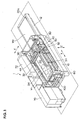
- FIG. 1 is a perspective view showing an overall configuration of a laser beam machine according to the present invention
- FIG. 2 is a plan view
- FIG. 3 is a front view
- FIG. 4 is a perspective view of the relevant portion
- FIG. 5 is a side view.
- a laser beam machine generally denoted by reference number 1, has a pallet (table) 20 which is disposed on a bed 10 to carry a plate-shaped workpiece W 1 .
- a pallet changer 12 is placed on the longitudinal extension of the bed 10, and a pallet 20a carrying a workpiece W 2 to be machined next is awaiting its turn.
- a pair of guide rails 34 are installed on both sides of the bed 10 along its length and a column 30 is mounted on the guide rails 34 in such a way as to be movable along an X axis.
- Means for driving the column 30 along the X axis is provided by, for example, a linear motor, which is formed by a stator installed on the guide rails 34 and a moving member installed on a linear-motion guide 32.
- a guide rail 44 is installed on the column 30 along a Y axis orthogonal to the X axis and a saddle 40 is mounted in such a way as to be movable along the Y axis.
- the saddle 40 is equipped with a linear-motion guide 42 which is engaged with the guide rail 44.
- a linear motor is formed by the guide rail 44 and linear-motion guide 42.
- the saddle 40 has a guide rail installed along a Z axis perpendicular to the plane formed by the X axis and Y axis and has a machining head 50 mounted in such a way as to be movable along the Z axis.
- the machining head 50 has an optical system which admits a laser beam from a laser oscillator 72.
- the machining head 50 is equipped replaceably with a laser machining tool 60.
- a machining area is fitted with a cover 90 to ensure safety.
- a power panel 70 and the laser oscillator 72 are disposed adjacent to the bed 10.
- a control panel 80 for use by the operator to give various commands is disposed on a longitudinal end of the bed 10.
- a setup station 100 for laser machining tools is installed on that end of the bed 10 which is closer to the control panel 80.
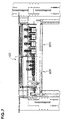
- FIG. 6 is a front view of the setup station 100 for laser machining tools as viewed from the table and
- FIG. 7 is a plan view.
- the setup station 100 for laser machining tools includes a tool station 200 and nozzle station 300, where the tool station 200 is equipped with a tool change magazine for laser machining tools which in turn are equipped with a torch and nozzle while the nozzle station 300 is equipped with a nozzle change magazine for nozzles of laser machining tools.
- FIG. 8 is an explanatory diagram illustrating a whisker-like burr removal apparatus according to the present invention.
- the laser machining tool 60 When the laser machining tool 60 produces, for example, pilot holes PH in aworkpiece W (made of stainless steel, aluminum, or the like) placed on tapered pin-shaped supports K1, the laser machining tool 60 jets out assist gas G1 together with a laser beam.
- aworkpiece W made of stainless steel, aluminum, or the like
- whisker-like burrs Wb are formed on the top surface of the workpiece when pilot holes PH are produced.
- the whisker-like burrs Wb are formed as molten particles of the stainless steel workpiece W scattered above under the pressure of the assist gas G1 and then cool down.
- the laser machining tool 60 moves over the workpiece W, being profile-controlled at a predetermined height position above the top surface Wa of the workpiece W.
- the profile control is performed using a profile sensor which senses capacitance between the laser machining tool 60 and the top surface of Wa of the workpiece.
- the whisker-like burr removal apparatus has the capability to remove the whisker-like burrs Wb formed on the top surface Wa of the workpiece W.
- the whisker-like burr removal apparatus 700 has a machining head 710 which incorporates a motor and which is equipped with a machining tool 730.
- the machining head 710 is mounted in such a way as to be raised and lowered by a cylinder 720.
- the machining head 710 When whisker-like burrs Wb are formed on the top surface Wa of the workpiece W, the machining head 710 is lowered to just above the whisker-like burrs Wb and the machining tool 730 removes the whisker-like burrs Wb.
- a cylindrical grinding stone, end mill, or the like is used as the machining tool 730.
- the whisker-like burr removal apparatus 700 can be mounted on appropriate part of the machining head or the saddle of the laser beam machine. Alternatively, it can be mounted on the laser beam machine as a unit separate from the machining head.
- the removal of whisker-like burrs can be carried out while the machining head is machining another portion.
- a piercing program extracted from a nesting program created on a CAM or NC system can be used for control.
Landscapes
- Engineering & Computer Science (AREA)
- Physics & Mathematics (AREA)
- Optics & Photonics (AREA)
- Mechanical Engineering (AREA)
- Plasma & Fusion (AREA)
- Robotics (AREA)
- Laser Beam Processing (AREA)
Abstract
Description
Claims (6)
- A burr removal apparatus for a laser beam machine that comprises a bed, a pallet which is disposed on the bed and holds a workpiece, a column which moves along an X axis, that is, in a longitudinal axis of the bed, a saddle which is supported by the column and moves along a Y axis orthogonal to the X axis, and a machining head which is supported by the saddle and moves along a Z axis perpendicular to a plane formed by the X axis and Y axis, characterized in that the laser beammachine comprises a remover of burrs formed on a top surface of a workpiece during laser machining.
- The burr removal apparatus for a laser beam machine according to claim 1, characterized in that the burrs are whisker-like burrs.
- The burr removal apparatus for a laser beam machine according to claim 1, characterized in that the workpiece is made of stainless steel or aluminum material.
- The burr removal apparatus for a laser beam machine according to claim 1, characterized in that the burrs are formed of molten particles.
- The burr removal apparatus for a laser beam machine according to claim 1, characterized by comprising a machining head raised and lowered from/to a workpiece surface, and a machining tool driven to rotate by the machining head.
- The burr removal apparatus for a laser beam machine according to claim 5, characterized in that the machining tool is a grinding tool or a cutting tool.
Applications Claiming Priority (2)
| Application Number | Priority Date | Filing Date | Title |
|---|---|---|---|
| JP2004155955A JP2005334927A (en) | 2004-05-26 | 2004-05-26 | Projection removal processing apparatus in laser processing machine |
| JP2004155955 | 2004-05-26 |
Publications (2)
| Publication Number | Publication Date |
|---|---|
| EP1602441A1 true EP1602441A1 (en) | 2005-12-07 |
| EP1602441B1 EP1602441B1 (en) | 2007-08-01 |
Family
ID=34936215
Family Applications (1)
| Application Number | Title | Priority Date | Filing Date |
|---|---|---|---|
| EP05009908A Expired - Lifetime EP1602441B1 (en) | 2004-05-26 | 2005-05-06 | Laser beam machine comprising a burr removal device |
Country Status (5)
| Country | Link |
|---|---|
| US (1) | US7159294B2 (en) |
| EP (1) | EP1602441B1 (en) |
| JP (1) | JP2005334927A (en) |
| CN (1) | CN100493810C (en) |
| DE (1) | DE602005001804T2 (en) |
Cited By (3)
| Publication number | Priority date | Publication date | Assignee | Title |
|---|---|---|---|---|
| EP1859893A1 (en) * | 2006-05-26 | 2007-11-28 | Yamazaki Mazak Corporation | Laser processing machine with exchangeable laser processing tool and machining tool |
| US7745756B2 (en) | 2004-11-29 | 2010-06-29 | Yamazaki Mazak Corporation | Laser processing machine |
| ES2830762A1 (en) * | 2019-10-22 | 2021-06-04 | Fund Tekniker | METHOD AND APPARATUS FOR DEBURING WORKPIECES |
Families Citing this family (17)
| Publication number | Priority date | Publication date | Assignee | Title |
|---|---|---|---|---|
| US7357769B2 (en) * | 2005-05-25 | 2008-04-15 | Mori Seiki Co., Ltd. | Machine tool |
| JP5030606B2 (en) * | 2007-01-30 | 2012-09-19 | ヤマザキマザック株式会社 | Machining center |
| WO2008153028A1 (en) * | 2007-06-11 | 2008-12-18 | Hitachi Metals, Ltd. | Laser working method, and oil ring wire rod |
| EP2939755A4 (en) * | 2012-12-27 | 2016-09-28 | Murata Machinery Ltd | Deburring tool for laser beam machine and deburring method therefor |
| CN103286454A (en) * | 2013-06-08 | 2013-09-11 | 爱司帝光电科技(苏州)有限公司 | Laser precision machining system and laser rough edge removing method |
| US20160023303A1 (en) * | 2014-07-22 | 2016-01-28 | Siemens Energy, Inc. | Method for forming three-dimensional anchoring structures |
| WO2016129879A1 (en) * | 2015-02-09 | 2016-08-18 | 두산공작기계 주식회사 | Five-axis processing machine |
| EP3213859B1 (en) * | 2016-03-01 | 2023-05-17 | Bystronic Laser AG | Laser processing machine with residue removing device |
| CN106736580B (en) * | 2016-12-27 | 2023-10-31 | 徐州启峰智能科技有限公司 | Sales terminal card swipe slot processing device |
| US11583963B2 (en) * | 2017-09-06 | 2023-02-21 | Hirata Corporation | Processing device and processing system |
| CN108381189B (en) * | 2018-04-27 | 2024-05-07 | 苏州英达瑞科技有限公司 | Automatic deburring production line for escalator steps |
| CN110465748A (en) * | 2019-08-27 | 2019-11-19 | 江山市合硕文具有限公司 | It is a kind of can automatic polishing laser marking machine |
| CN111604690A (en) * | 2020-06-02 | 2020-09-01 | 吕子乒 | Automatic welding device |
| CN111644854A (en) * | 2020-06-05 | 2020-09-11 | 赣州逸豪新材料股份有限公司 | Automatic aluminum substrate cutting and drilling equipment |
| CN112276590B (en) * | 2020-10-23 | 2021-12-24 | 山东中车同力达智能装备有限公司 | Full-automatic welding system and production line for cross rods |
| CN117840758B (en) * | 2024-03-05 | 2024-05-03 | 烟台三水电器有限公司 | Automatic processing equipment for partition plate of power distribution cabinet |
| CN118543995B (en) * | 2024-07-29 | 2024-11-22 | 江苏盛阳消防门业有限公司 | Cutting equipment that fire control steel door processing was used |
Citations (6)
| Publication number | Priority date | Publication date | Assignee | Title |
|---|---|---|---|---|
| JPS61182876A (en) * | 1985-02-07 | 1986-08-15 | Kawasaki Steel Corp | Welding equipment having grinding equipment |
| US4661680A (en) * | 1985-06-28 | 1987-04-28 | Westinghouse Electric Corp. | End-of-arm tooling carousel apparatus for use with a robot |
| US5548890A (en) * | 1992-11-24 | 1996-08-27 | Hitachi Construction Machinery Co., Ltd. | Lead frame processing method |
| JPH11207586A (en) * | 1998-01-22 | 1999-08-03 | Amada Co Ltd | Deburring device |
| EP1057575A2 (en) * | 1999-05-28 | 2000-12-06 | Hitachi, Ltd. | A method of manufacturing a structural body and a apparatus therefor |
| JP2004074254A (en) * | 2002-08-21 | 2004-03-11 | Komatsu Sanki Kk | Cutting machine by using plasma arc or laser, and its cutting method |
Family Cites Families (14)
| Publication number | Priority date | Publication date | Assignee | Title |
|---|---|---|---|---|
| US4559684A (en) * | 1981-02-27 | 1985-12-24 | Pryor Timothy R | Controlled machining of combustion chambers, gears and other surfaces |
| US4469930A (en) * | 1981-07-17 | 1984-09-04 | Fuji Tool & Die Co., Ltd. | Three-dimensional laser cutting system by a playback method |
| DE3503736C1 (en) | 1985-02-04 | 1985-12-05 | M.A.N.- Roland Druckmaschinen AG, 6050 Offenbach | Ink metering device on printing machines |
| JPS6395693A (en) | 1986-10-13 | 1988-04-26 | Matsushita Electric Ind Co Ltd | Semiconductor laser device |
| US5351399A (en) * | 1989-08-03 | 1994-10-04 | Schwabische Huttenwerke Gmbh | Method for forming grooves in roll surfaces |
| JP2800949B2 (en) | 1990-05-11 | 1998-09-21 | 株式会社アマダ | Nozzle centering device for laser beam machine |
| JPH07266075A (en) | 1994-03-31 | 1995-10-17 | Komatsu Ltd | Dross removing device for heat cutting machine |
| CA2301351C (en) * | 1994-11-28 | 2002-01-22 | Advanced Cardiovascular Systems, Inc. | Method and apparatus for direct laser cutting of metal stents |
| JPH10314969A (en) | 1997-05-21 | 1998-12-02 | Sumitomo Heavy Ind Ltd | Observation device for laser beam machine |
| US6347259B1 (en) * | 1999-04-01 | 2002-02-12 | Virtek Vision International Inc. | High precision positioning device and method of operating same |
| US6392192B1 (en) * | 1999-09-15 | 2002-05-21 | W. A. Whitney Co. | Real time control of laser beam characteristics in a laser-equipped machine tool |
| DE10012792B4 (en) * | 2000-03-13 | 2011-06-16 | Fraunhofer-Gesellschaft zur Förderung der angewandten Forschung e.V. | Method for cutting components, in which a molten phase is generated by a local energy input |
| JP3865226B2 (en) | 2002-03-26 | 2007-01-10 | 住友重機械工業株式会社 | Laser processing method, laser processing apparatus, and laser processing program |
| CN2573125Y (en) * | 2002-10-25 | 2003-09-17 | 沈阳工业学院 | Vertical high-speed NC milling machine |
-
2004
- 2004-05-26 JP JP2004155955A patent/JP2005334927A/en active Pending
-
2005
- 2005-05-04 US US11/121,427 patent/US7159294B2/en not_active Expired - Fee Related
- 2005-05-06 DE DE602005001804T patent/DE602005001804T2/en not_active Expired - Lifetime
- 2005-05-06 EP EP05009908A patent/EP1602441B1/en not_active Expired - Lifetime
- 2005-05-26 CN CNB2005100738914A patent/CN100493810C/en not_active Expired - Fee Related
Patent Citations (6)
| Publication number | Priority date | Publication date | Assignee | Title |
|---|---|---|---|---|
| JPS61182876A (en) * | 1985-02-07 | 1986-08-15 | Kawasaki Steel Corp | Welding equipment having grinding equipment |
| US4661680A (en) * | 1985-06-28 | 1987-04-28 | Westinghouse Electric Corp. | End-of-arm tooling carousel apparatus for use with a robot |
| US5548890A (en) * | 1992-11-24 | 1996-08-27 | Hitachi Construction Machinery Co., Ltd. | Lead frame processing method |
| JPH11207586A (en) * | 1998-01-22 | 1999-08-03 | Amada Co Ltd | Deburring device |
| EP1057575A2 (en) * | 1999-05-28 | 2000-12-06 | Hitachi, Ltd. | A method of manufacturing a structural body and a apparatus therefor |
| JP2004074254A (en) * | 2002-08-21 | 2004-03-11 | Komatsu Sanki Kk | Cutting machine by using plasma arc or laser, and its cutting method |
Non-Patent Citations (3)
| Title |
|---|
| PATENT ABSTRACTS OF JAPAN vol. 011, no. 006 (M - 551) 8 January 1987 (1987-01-08) * |
| PATENT ABSTRACTS OF JAPAN vol. 1999, no. 13 30 November 1999 (1999-11-30) * |
| PATENT ABSTRACTS OF JAPAN vol. 2003, no. 12 5 December 2003 (2003-12-05) * |
Cited By (3)
| Publication number | Priority date | Publication date | Assignee | Title |
|---|---|---|---|---|
| US7745756B2 (en) | 2004-11-29 | 2010-06-29 | Yamazaki Mazak Corporation | Laser processing machine |
| EP1859893A1 (en) * | 2006-05-26 | 2007-11-28 | Yamazaki Mazak Corporation | Laser processing machine with exchangeable laser processing tool and machining tool |
| ES2830762A1 (en) * | 2019-10-22 | 2021-06-04 | Fund Tekniker | METHOD AND APPARATUS FOR DEBURING WORKPIECES |
Also Published As
| Publication number | Publication date |
|---|---|
| CN1701894A (en) | 2005-11-30 |
| DE602005001804T2 (en) | 2008-04-10 |
| EP1602441B1 (en) | 2007-08-01 |
| JP2005334927A (en) | 2005-12-08 |
| DE602005001804D1 (en) | 2007-09-13 |
| CN100493810C (en) | 2009-06-03 |
| US7159294B2 (en) | 2007-01-09 |
| US20050262684A1 (en) | 2005-12-01 |
Similar Documents
| Publication | Publication Date | Title |
|---|---|---|
| US7159294B2 (en) | Burr removal apparatus for laser beam machine | |
| EP3090858B1 (en) | Double-head cutting saw with automatic processing function | |
| US6327761B1 (en) | Apparatus for machining a flat metallic workpiece | |
| WO2013145929A1 (en) | Combined processing method and combined processing device | |
| JPH10180585A (en) | Machine tools with automatic chip removal equipment | |
| JPS6043837B2 (en) | Laser processing equipment | |
| CN114571059A (en) | Sheet metal dadoing and laser cutting compounding machine with keep away empty structure | |
| EP1600241B1 (en) | Focus adjuster for laser beam machine | |
| JP2004243393A (en) | Laser welding system | |
| CN210524194U (en) | Self-detection teaching laser cutting machine | |
| JP2006102812A (en) | Laser processing machine | |
| JPH0857654A (en) | Plasma cutting device | |
| KR20190066181A (en) | Automatic beveler device | |
| EP1759804A1 (en) | Laser processing machine comprising a nozzle polishing device | |
| JPH0526617B2 (en) | ||
| CN210657827U (en) | Rail saw milling integrated device | |
| KR101098883B1 (en) | Plazma cutting device | |
| JPS60238217A (en) | Method and device for machining tube | |
| US4632365A (en) | Apparatus for the torch cutting of a steel structural shape | |
| JP2006175580A (en) | Grinding device for nozzle in laser beam machine | |
| KR200180053Y1 (en) | Processing apparatus for a surface defect of burr remover in cold strip | |
| CN221110272U (en) | Metal sheet keyway cutting all-in-one | |
| JPH0433575B2 (en) | ||
| CN217096768U (en) | Automatic blanking equipment | |
| US7649155B2 (en) | Piercing method for laser beam machine |
Legal Events
| Date | Code | Title | Description |
|---|---|---|---|
| PUAI | Public reference made under article 153(3) epc to a published international application that has entered the european phase |
Free format text: ORIGINAL CODE: 0009012 |
|
| AK | Designated contracting states |
Kind code of ref document: A1 Designated state(s): AT BE BG CH CY CZ DE DK EE ES FI FR GB GR HU IE IS IT LI LT LU MC NL PL PT RO SE SI SK TR |
|
| AX | Request for extension of the european patent |
Extension state: AL BA HR LV MK YU |
|
| 17P | Request for examination filed |
Effective date: 20051222 |
|
| AKX | Designation fees paid |
Designated state(s): DE FR GB IT |
|
| GRAP | Despatch of communication of intention to grant a patent |
Free format text: ORIGINAL CODE: EPIDOSNIGR1 |
|
| GRAS | Grant fee paid |
Free format text: ORIGINAL CODE: EPIDOSNIGR3 |
|
| GRAA | (expected) grant |
Free format text: ORIGINAL CODE: 0009210 |
|
| AK | Designated contracting states |
Kind code of ref document: B1 Designated state(s): DE FR GB IT |
|
| REG | Reference to a national code |
Ref country code: GB Ref legal event code: FG4D |
|
| REF | Corresponds to: |
Ref document number: 602005001804 Country of ref document: DE Date of ref document: 20070913 Kind code of ref document: P |
|
| ET | Fr: translation filed | ||
| PLBE | No opposition filed within time limit |
Free format text: ORIGINAL CODE: 0009261 |
|
| STAA | Information on the status of an ep patent application or granted ep patent |
Free format text: STATUS: NO OPPOSITION FILED WITHIN TIME LIMIT |
|
| 26N | No opposition filed |
Effective date: 20080506 |
|
| REG | Reference to a national code |
Ref country code: FR Ref legal event code: PLFP Year of fee payment: 12 |
|
| PGFP | Annual fee paid to national office [announced via postgrant information from national office to epo] |
Ref country code: DE Payment date: 20160504 Year of fee payment: 12 Ref country code: GB Payment date: 20160504 Year of fee payment: 12 |
|
| PGFP | Annual fee paid to national office [announced via postgrant information from national office to epo] |
Ref country code: IT Payment date: 20160524 Year of fee payment: 12 Ref country code: FR Payment date: 20160412 Year of fee payment: 12 |
|
| REG | Reference to a national code |
Ref country code: DE Ref legal event code: R119 Ref document number: 602005001804 Country of ref document: DE |
|
| GBPC | Gb: european patent ceased through non-payment of renewal fee |
Effective date: 20170506 |
|
| REG | Reference to a national code |
Ref country code: FR Ref legal event code: ST Effective date: 20180131 |
|
| PG25 | Lapsed in a contracting state [announced via postgrant information from national office to epo] |
Ref country code: DE Free format text: LAPSE BECAUSE OF NON-PAYMENT OF DUE FEES Effective date: 20171201 Ref country code: GB Free format text: LAPSE BECAUSE OF NON-PAYMENT OF DUE FEES Effective date: 20170506 |
|
| PG25 | Lapsed in a contracting state [announced via postgrant information from national office to epo] |
Ref country code: IT Free format text: LAPSE BECAUSE OF NON-PAYMENT OF DUE FEES Effective date: 20170506 Ref country code: FR Free format text: LAPSE BECAUSE OF NON-PAYMENT OF DUE FEES Effective date: 20170531 |