EP1601245B1 - Remote control for hose operation - Google Patents
Remote control for hose operation Download PDFInfo
- Publication number
- EP1601245B1 EP1601245B1 EP20040737327 EP04737327A EP1601245B1 EP 1601245 B1 EP1601245 B1 EP 1601245B1 EP 20040737327 EP20040737327 EP 20040737327 EP 04737327 A EP04737327 A EP 04737327A EP 1601245 B1 EP1601245 B1 EP 1601245B1
- Authority
- EP
- European Patent Office
- Prior art keywords
- wireless
- hose
- valve
- receiver
- control system
- Prior art date
- Legal status (The legal status is an assumption and is not a legal conclusion. Google has not performed a legal analysis and makes no representation as to the accuracy of the status listed.)
- Expired - Lifetime
Links
- 239000012530 fluid Substances 0.000 claims abstract description 43
- 238000004891 communication Methods 0.000 claims abstract description 15
- 238000000034 method Methods 0.000 claims description 37
- XLYOFNOQVPJJNP-UHFFFAOYSA-N water Substances O XLYOFNOQVPJJNP-UHFFFAOYSA-N 0.000 claims description 31
- 238000001514 detection method Methods 0.000 claims description 24
- 230000004044 response Effects 0.000 claims description 11
- 230000008569 process Effects 0.000 claims description 10
- 230000003213 activating effect Effects 0.000 claims 1
- 239000003990 capacitor Substances 0.000 description 19
- 230000008901 benefit Effects 0.000 description 11
- 230000007423 decrease Effects 0.000 description 11
- 239000007921 spray Substances 0.000 description 5
- 230000007246 mechanism Effects 0.000 description 4
- 230000000153 supplemental effect Effects 0.000 description 4
- 230000008859 change Effects 0.000 description 3
- 230000005611 electricity Effects 0.000 description 3
- 230000004048 modification Effects 0.000 description 3
- 238000012986 modification Methods 0.000 description 3
- 238000011144 upstream manufacturing Methods 0.000 description 3
- 230000009286 beneficial effect Effects 0.000 description 2
- 230000000694 effects Effects 0.000 description 2
- 229920006395 saturated elastomer Polymers 0.000 description 2
- 238000004804 winding Methods 0.000 description 2
- 230000004913 activation Effects 0.000 description 1
- 238000007792 addition Methods 0.000 description 1
- 230000004075 alteration Effects 0.000 description 1
- 238000004458 analytical method Methods 0.000 description 1
- 230000005670 electromagnetic radiation Effects 0.000 description 1
- 239000002360 explosive Substances 0.000 description 1
- 239000007789 gas Substances 0.000 description 1
- 231100001261 hazardous Toxicity 0.000 description 1
- 230000000977 initiatory effect Effects 0.000 description 1
- 239000007788 liquid Substances 0.000 description 1
- 230000003278 mimic effect Effects 0.000 description 1
- 238000012544 monitoring process Methods 0.000 description 1
- 238000011176 pooling Methods 0.000 description 1
- 238000007493 shaping process Methods 0.000 description 1
- 239000000126 substance Substances 0.000 description 1
- 238000005406 washing Methods 0.000 description 1
Images


Classifications
-
- B—PERFORMING OPERATIONS; TRANSPORTING
- B65—CONVEYING; PACKING; STORING; HANDLING THIN OR FILAMENTARY MATERIAL
- B65H—HANDLING THIN OR FILAMENTARY MATERIAL, e.g. SHEETS, WEBS, CABLES
- B65H75/00—Storing webs, tapes, or filamentary material, e.g. on reels
- B65H75/02—Cores, formers, supports, or holders for coiled, wound, or folded material, e.g. reels, spindles, bobbins, cop tubes, cans, mandrels or chucks
- B65H75/34—Cores, formers, supports, or holders for coiled, wound, or folded material, e.g. reels, spindles, bobbins, cop tubes, cans, mandrels or chucks specially adapted or mounted for storing and repeatedly paying-out and re-storing lengths of material provided for particular purposes, e.g. anchored hoses, power cables
- B65H75/38—Cores, formers, supports, or holders for coiled, wound, or folded material, e.g. reels, spindles, bobbins, cop tubes, cans, mandrels or chucks specially adapted or mounted for storing and repeatedly paying-out and re-storing lengths of material provided for particular purposes, e.g. anchored hoses, power cables involving the use of a core or former internal to, and supporting, a stored package of material
- B65H75/44—Constructional details
- B65H75/4481—Arrangements or adaptations for driving the reel or the material
- B65H75/4486—Electric motors
-
- A—HUMAN NECESSITIES
- A01—AGRICULTURE; FORESTRY; ANIMAL HUSBANDRY; HUNTING; TRAPPING; FISHING
- A01G—HORTICULTURE; CULTIVATION OF VEGETABLES, FLOWERS, RICE, FRUIT, VINES, HOPS OR SEAWEED; FORESTRY; WATERING
- A01G25/00—Watering gardens, fields, sports grounds or the like
- A01G25/16—Control of watering
- A01G25/162—Sequential operation
-
- B—PERFORMING OPERATIONS; TRANSPORTING
- B65—CONVEYING; PACKING; STORING; HANDLING THIN OR FILAMENTARY MATERIAL
- B65H—HANDLING THIN OR FILAMENTARY MATERIAL, e.g. SHEETS, WEBS, CABLES
- B65H75/00—Storing webs, tapes, or filamentary material, e.g. on reels
- B65H75/02—Cores, formers, supports, or holders for coiled, wound, or folded material, e.g. reels, spindles, bobbins, cop tubes, cans, mandrels or chucks
- B65H75/34—Cores, formers, supports, or holders for coiled, wound, or folded material, e.g. reels, spindles, bobbins, cop tubes, cans, mandrels or chucks specially adapted or mounted for storing and repeatedly paying-out and re-storing lengths of material provided for particular purposes, e.g. anchored hoses, power cables
- B65H75/38—Cores, formers, supports, or holders for coiled, wound, or folded material, e.g. reels, spindles, bobbins, cop tubes, cans, mandrels or chucks specially adapted or mounted for storing and repeatedly paying-out and re-storing lengths of material provided for particular purposes, e.g. anchored hoses, power cables involving the use of a core or former internal to, and supporting, a stored package of material
- B65H75/44—Constructional details
- B65H75/4481—Arrangements or adaptations for driving the reel or the material
- B65H75/4484—Electronic arrangements or adaptations for controlling the winding or unwinding process, e.g. with sensors
-
- B—PERFORMING OPERATIONS; TRANSPORTING
- B65—CONVEYING; PACKING; STORING; HANDLING THIN OR FILAMENTARY MATERIAL
- B65H—HANDLING THIN OR FILAMENTARY MATERIAL, e.g. SHEETS, WEBS, CABLES
- B65H2551/00—Means for control to be used by operator; User interfaces
- B65H2551/10—Command input means
- B65H2551/13—Remote control devices, e.g. speech recognition
-
- B—PERFORMING OPERATIONS; TRANSPORTING
- B65—CONVEYING; PACKING; STORING; HANDLING THIN OR FILAMENTARY MATERIAL
- B65H—HANDLING THIN OR FILAMENTARY MATERIAL, e.g. SHEETS, WEBS, CABLES
- B65H2701/00—Handled material; Storage means
- B65H2701/30—Handled filamentary material
- B65H2701/33—Hollow or hose-like material
-
- Y—GENERAL TAGGING OF NEW TECHNOLOGICAL DEVELOPMENTS; GENERAL TAGGING OF CROSS-SECTIONAL TECHNOLOGIES SPANNING OVER SEVERAL SECTIONS OF THE IPC; TECHNICAL SUBJECTS COVERED BY FORMER USPC CROSS-REFERENCE ART COLLECTIONS [XRACs] AND DIGESTS
- Y10—TECHNICAL SUBJECTS COVERED BY FORMER USPC
- Y10T—TECHNICAL SUBJECTS COVERED BY FORMER US CLASSIFICATION
- Y10T137/00—Fluid handling
- Y10T137/6851—With casing, support, protector or static constructional installations
- Y10T137/6918—With hose storage or retrieval means
- Y10T137/6932—With retrieval means
Definitions
- This invention relates generally to hose systems and more particularly to controlling fluid flow and reel operations of hose systems.
- the invention further relates to power saving aspects of the same.
- Hoses are typically used in conjunction with on/off valves positioned at a distal or proximal end of the hose.
- garden hoses are fitted to a faucet on the outside of a house or other building, with a traditional manual spigot or valve for turning the water flow on or off at the faucet.
- a traditional manual spigot or valve for turning the water flow on or off at the faucet.
- the hose is designed to extend many yards away from the faucet, it is often convenient to have a means for turning the flow on or off at the distal or spray nozzle end of the hose.
- many manual devices such as spray guns are provided for fitting at the nozzle end of the hose so that the flow can be turned on or off without repeatedly returning to the faucet.
- Remote control systems generally involve a remote transmitter powered by a battery, or low power source, and the unit to be controlled.
- the unit to be controlled is connected to a receiver that is usually powered by a continuous power source, lather than a battery.
- the remote transmitter is typically powered by batteries and thus truly “wireless,” the receiver is usually connected to a larger, or continuous, source of power by a wire.
- the receiver cannot function in this way because it does not know when a command will be sent to it In other words, in traditional arrangements, the receiver must continuously monitor for incoming signals and, therefore, must be on at all times. The power that is needed to continuously monitor for an incoming signal would normally drain a battery in a few days. This makes a fully wireless, or battery-operated remotely controllable device, impractical.
- Such a hose control system comprising a flow controller and a wireless remote control, is known from US 6,283,139 B1 .
- the present application provides a hose control system according to claim 1 that permits remote control of supplemental flow controllers and motorized reels for hose systems.
- the present invention provides a hose control system comprising a flow controller, a hose reel device, electronic components, and a remote control.
- the flow controller includes an inlet, an outlet, a fluid flow path defined between the inlet and outlet, and an electrically actuated valve positioned to selectively close the fluid flow path.
- the hose reel device which is in fluid communication with the outlet of the flow controller, comprises a rotatable drum onto which a hose can be spooled, and an electrical motor connected to rotate the drum.
- the electronic components are in communication with, and are configured to convey electrical power to drive, the valve and the motor.
- the electronic components comprise a wireless receiver configured to receive wireless command signals for controlling the valve and the motor.
- the remote control comprises manual controls and a wireless transmitter.
- the wireless transmitter is configured to transmit command signals to the wireless receiver for controlling the valve and the motor.
- the manual controls are connected to the wireless transmitter to permit control of the wireless transmitter.
- the present invention provides a hose control system comprising a flow controller, a rotatable hose reel drum onto which a hose can be spooled, an electrically controllable motor connected to rotate the drum, electronic components, and a remote control.
- the flow controller has an inlet, an outlet, a fluid flow path defined between the inlet and outlet, and an electrically actuated valve positioned to selectively close the fluid flow path.
- the electronic components are in communication with the valve and the motor.
- the remote control is configured to transmit wireless command signals to the electronic components for controlling the valve and the motor.
- the present invention provides a hose control system comprising a flow controller, a rotatable hose reel drum onto which a hose can be spooled, a motor connected to rotate the drum, a receiver, and a remote control.
- the flow controller has an inlet, an outlet, a fluid flow path defined between the inlet and outlet, and a valve positioned to selectively close the fluid flow path.
- the inlet is configured to mate with a residential water faucet, and the outlet is configured to mate with a water hose.
- the receiver is configured to receive wireless command signals for controlling the valve and the - motor.
- the remote control is configured to transmit wireless command signals to the receiver for controlling the valve and the motor.
- the present invention provides a power savings system comprising a wireless receiver and a power control unit.
- the wireless receiver is configured to receive wireless signals for controlling at least one of an electrical motor driving rotation of a hose reel and an electrically actuated valve controlling a fluid flow through a hose system.
- the wireless receiver is capable of receiving the wireless signals only when the wireless receiver is in a powered state.
- the power control unit is configured to repeatedly switch the wireless receiver between powered and unpowered states in a cycle.
- the power control unit is configured to keep the wireless receiver in its unpowered state for no more than a set time period during each cycle.
- the system further comprises a remote control configured to transmit wireless command signals for controlling at least one of the motor and the valve, the remote control configured so that each signal is transmitted for a duration at least as long as the set time period.
- the present invention provides a power savings system comprising a wireless receiver and a power control unit.
- the wireless receiver is configured to receive wireless signals for controlling at least one of an electrical motor driving rotation of a hose reel and an electrically actuated valve controlling a fluid flow through a hose system.
- the wireless receiver is capable of receiving the wireless signals only when the wireless receiver is in a powered state.
- the power control unit is configured to reduce power consumption by applying an initial voltage to initiate movement of a mechanical device and then reducing the voltage to the mechanical device after the mechanical device begins moving and before the mechanical device is intended to stop:
- the mechanical device is the valve.
- the mechanical device is the motor.
- the present invention provides the following method according to claim 27 :
- a wireless valve command signal is received for controlling an electrically actuated valve, the valve positioned to selectively close a fluid flow path through a hose system.
- the valve is positioned in response to the wireless valve command signal.
- a wireless reel command signal is received for controlling an electrical motor connected to rotate a drum onto which hose can be spooled. The motor is activated in response to the wireless reel command signal.
- the present invention provides the following method according to claim 38: A wireless valve command signal is transmitted from a remote control to a wireless receiver. Fluid flow through a hose system is controlled in accordance with the wireless valve command signal. A wireless reel command signal is transmitted from the remote control to the wireless receiver. An electric motor is controlled in accordance with the wireless reel command signal, the motor connected to rotate a rotatable reel drum onto which hose can be spooled.
- the present invention provides a method of conserving power in the detection of a wireless signal from a remote transmitter.
- a wireless receiver is repeatedly switched between powered and unpowered states in a cycle.
- the wireless receiver is configured to receive wireless signals for controlling at least one of an electrical motor driving rotation of a hose reel and an electrically actuated valve controlling a fluid flow through a hose system.
- the wireless receiver is capable of receiving the wireless signals only when the wireless receiver is in its powered state. If the wireless receiver receives a wireless signal while in its powered state, switching the wireless receiver to its unpowered state is ceased.
- the present invention provides a power saving valve controller comprising a flow controller and electronic components in communication with the flow controller.
- the flow controller comprises an inlet, an outlet, a fluid flow path defined between the inlet and outlet, and an electrically actuated valve positioned to selectively close the fluid flow path.
- the electronic components comprise a wireless receiver configured to receive wireless command signals for controlling the valve, and a power control unit configured to repeatedly switch the wireless receiver between powered and unpowered states in a cycle.
- the present invention provides a power saving valve controller comprising a flow controller and electronic components in communication with the flow controller.
- the flow controller comprises an inlet, an outlet, a fluid flow path defined between the inlet and outlet, and an electrically actuated valve positioned to selectively close the fluid flow path.
- the electronic components comprise a wireless receiver and a power control unit.
- the receiver is configured to receive wireless command signals for controlling the valve.
- the power control unit is configured to reduce power consumption by applying an initial voltage to initiate movement of the valve and reducing the voltage to the valve after the valve begins moving but before movement of the valve is intended to stop.
- the present invention provides a method of reducing the power consumed by a flow controller.
- a receiver is repeatedly switched on and off, the receiver being configured to receive wireless command signals for controlling an electrically actuated valve of the flow controller. If the receiver receives a wireless command signal, the receiver is kept on to allow the receiver to transmit the command signal to the electrically actuated valve.
- the present invention provides a method of reducing the power consumed by a flow controller.
- an electronic logic unit is kept in an unpowered state until a detection unit detects a wireless signal, the electronic logic unit being configured to receive the signal from the detection unit and process the signal to control a valve in the flow controller.
- the electronic logic unit is powered when the detection unit detects a wireless signal.
- the present invention provides a method of reducing the power consumption of a system for controlling at least one of fluid flow in a hose system and a motor driving rotation of a reel drum for pooling a hose of the hose system.
- an initial voltage is applied to initiate movement of a mechanical device. The initial voltage is reduced after the mechanical device begins moving but before the mechanical device is instructed to stop moving.
- the fluid flow through the hose can comprise compressed air or vacuum suction for other applications.
- FIG. 1A illustrates one embodiment of the present invention.
- a fluid source is illustrated in the form of a water faucet 10 extending from the wall of a building 12.
- the faucet 10 includes a valve or spigot with a manual control 14.
- a hose line 16 in communication with the faucet 10 extends from a proximal end 18 to a distal end 20, terminating in a nozzle 22.
- the nozzle 22 is conventionally configured to receive attachments.
- the nozzle receives a manually actuated nozzle attachment (not shown), such as a spray gun.
- a flow controller 30 is positioned at some point between the distal end 20 of the hose line 16 and the water faucet 10.
- the flow controller 30, shown in more detail in Figure 1B defines a fluid flow path 32 from an inlet 34 to an outlet 36.
- the inlet 34 is configured with internal threading to receive the external threads of a conventional faucet outlet.
- the flow controller outlet 36 defines external threads of a standard diameter and pitch to receive the internal threads of a conventional garden hose connection.
- an electrically actuated valve 38 such as a solenoid valve, for example, selectively permits or inhibits flow therethrough.
- Such electrically actuated valves with inlets and outlets are known in commercially available sprinkler timing systems.
- supplemental is used to describe the flow controller 30, the flow controller may still be the only controller in the system. In other words, the term “supplemental” is not necessarily meant to suggest that there must be other means of controlling the flow; rather, the term is used as an aid to distinguish this flow controller over other items, such as the manual control 14.
- the flow controller 30 includes electronics 40 configured to receive and communicate signals, or command signals, from a remote source such as a transmitter or remote control 50 ( Figures 1A, 3B , 4 and 5 ).
- a remote source such as a transmitter or remote control 50
- the electronics 40 aided by an antenna 42, include a wireless receiver configured to receive electromagnetic signals from a remote source, and to translate those signals into signals that may open or close the electrically actuated valve 38.
- the flow controller 30 may be linked, via one or more wires 118, to a motor 114 that drives rotation of a reel drum 116.
- the flow controller 30 can send signals to control the operation of the motor 114 for the reel, the motor command signals being conveyed to the motor via the wire connection 118.
- the wire connection can also convey power to one or both of the flow controller 30 and the motor 114.
- the motor 114 is powered by connection of an electrical plug 120 to a power supply, the wire connection 118 conveying power to the flow controller 30. Examples of communication methods include infrared (IR) and radio frequency (RF) communications.
- IR infrared
- RF radio frequency
- the wireless receiver 41 will comprise some type of detection unit 44, such as an RF receiver integrated circuit (IC) chip, configured to detect incoming wireless signals. Additionally, the receiver 41 may comprise a logio unit or circuit 43, which is configured to analyse and decode incoming wireless signals detected by the detection unit 44 and determine what, if any, response should be generated. The receiver 41 is preferably configured to communicate, electrically, with an electrically driven device, in order that the electrical signals can be converted into a physical change, such as the actuation of a valve, for example.
- the detection unit 44 and the logic unit 43 need not be physically located within a single housing or receiver 41.
- antenna 42 the antenna can alternatively be incorporated within the housing of the flow controller 30.
- a self-contained DC power source in the form of batteries 47. It will be understood that the flow controller 30 can alternatively be powered by AC current from an electrical outlet on the building 12, or by solar cells or the like.
- the logic unit will be external to the receiver.
- This logic unit could be an Application-Specific Integrated Circuit (ASIC), or a standard IC decoder unit.
- ASIC Application-Specific Integrated Circuit
- the logic unit can preferably be powered down when it is not needed.
- the electronics 40 may include a "power control unit” that lowers the power consumption of the receiver 41.
- the power control unit 45 may be especially valuable when the receiver 41 is powered by batteries 47. As explained above in the Background section, a conventional wireless receiver consumes a great deal of power because the receiver must continually monitor for wireless commands. If the receiver is powered by batteries, the battery power would be exhausted in a very short period of time, such as a week or less The power control unit 45 overcomes this limitation.
- the receiver 41 may function for up to six months.
- the power control unit may allow a receiver to function for up to twenty times longer than a receiver without the power control unit.
- the power control unit 45 generally operates by shutting down the detection unit 44 of the receiver 41, and all other electronics for a "reasonable response time."
- a “reasonable response time” means a time period that a user would not notice or mind in the operation of the remote control transmitter 50.
- a “reasonable response time” is defined as slightly shorter than the duration that the signal from the remote control transmitter lasts 50. For example, when activation of the transmitter 50 results in a signal that lasts 3 seconds, then the shut down time on the detection unit 44 is preferably less than 3 seconds.
- the shut down time of the detection unit 44 is longer than the duration of the signal from the transmitter 50 In these embodiments, the transmitted signal may not be detected by the detection unit 44, which could cause more substantial wait times.
- the reasonable response time factors in the fact that some of the embodiments are as a water hose operated device, for which a user may be willing to wait several seconds before anything occurs at the user's location.
- a reasonable response time is a time period determined by the necessary life of the battery and the power currently in the battery.
- the power control unit 45 will only activate the detector unit approximately 1 second out of every 52 seconds.
- a 51 second down cycle could result in a very long delay between the initiation of the signal from the transmitter 50 to any flow of water through the hose 16, but this is merely an example of how the time periods could be set.
- the detector unit 44 needs only a fraction of a second to determine if a signal is being received. For example, the detector unit 44 could be on for 1/50 of a second, or 20 milliseconds, during each second. This would be a sufficient time to recognize if a signal is being received and would save a significant amount of power.
- the detection unit 45 searches for a signal. This process of repeatedly shutting on and off the detection unit 44, as well as other current draining equipment, limits the amount of power needed for continuously monitoring for incoming wireless signals. If the detection unit 44 does not detect a signal within a set amount of time, the power control unit 45 preferably turns off the power to the detection unit for another period of time, thus repeating a cycle.
- the power control 45 unit also turns off the logic unit 43.
- the logic unit 43 need not be automatically turned back on after a certain period of time. Instead, powering on the logic unit 43 on is only required when a wireless signal is detected by the detection unit 44. In one embodiment, this signal is a valid command from the remote transmitter 50 to open or close the valve 38 or activate the motor 114.
- the device can be configured to return to its power saving mode after a wireless signal has been detected and the signal ceases. That is, while the detection of a signal results in the power control unit 45 allowing the device to use more power, the end of a signal may also allow the power control unit to return the electronics 40 to their low power consumption state. In some embodiments it may be desirable to include a delay following the cessation of the signal, in case another signal is likely to follow. For example, it may be efficient to leave the electronics 40 fully operational, even after a signal to close the valve 38 has stopped being transmitted, as it may be likely that a signal to rewind the hose reel is soon to follow.
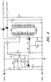
- the power control unit 45 employs an op-amp to switch the detection unit 44 on and off, repeatedly, in order to conserve battery life.
- the power control unit preferably comprises a very low power bi-stable oscillator.
- the oscillator comprises an op-amp U1A, a plurality of resistors R1, R2, R3, R4 and R5, a capacitor C1, and a diode D1.
- the op-amp U1A has a non-inverting input pin 3, an inverting input pin 4, and an output pin 1, among others.
- Resistors R1, R2, and R3 form a voltage divider, which provides one of two voltages to the non-inverting input pin 3 of the op-amp U1A.
- the resistor R3 provides hysteresis to stabilize the op-amp.
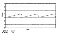
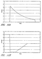
- Figures 7A, 7B , and 7C illustrate the voltages at the pins of the op-amp.
- Figure 7A is the voltage at the output pin 1 of the op-amp.
- Figure 7B is the voltage at the non-inverting input pin 3
- Figure 7C is the voltage at the inverting input pin 4.
- the voltage at non-inverting pin 3 is higher when the voltage at the output pin 1 is high because of the effects of the voltage divider.
- the capacitor C1 charges, gradually increasing the voltage at the inverting pin 4 until the voltage equals the voltage of the non-inverting pin 3.
- the op-amp U1A then changes the output of pin 1 to its low voltage, V ol . Because there are no capacitors connected to the non-inverting pin 3, and thus no time delay, the low output on pin 1 immediately reduces the voltage to pin 3.
- the low output voltage also causes current to flow though the resistors R4 and R5 and lowers the voltage across the capacitor C1. Voltage across a capacitor cannot change immediately, so the voltage at the inverting input 4 gradually decreases.
- the inverting duration (T n ) is proportional to the time constant of the combined resistance of resistors R3 and R4 in parallel multiplied by the capacitance of capacitor C1. This time constant is defined as ((R4*R3)/(R4 + R3))*C1.
- T n the time that the RF receiver U2 receives power, is proportional to the time constant.
- T n is 1/20 of the total cycle time, T n + T p .
- the RF receiver is on between about 2% and 20% of each cycle, more preferably between about 3% and 10%.
- the on and off duration can be further modified by making the resistors R1 and R2 unequal to form an additional voltage divider.
- the RF receiver U2 outputs a signal on the data pin 10 if there is a RF command being received.
- the output of data pin 10 is high, current conducts through a diode D2, charging the capacitor C2.
- the voltage across the capacitor C2 is above 0.6 volts, current conducts through a resistor R8 and the base-emitter junction of a transistor Q2.
- the transistor Q2 turns on and the voltage at the collector is close to ground. This causes current to flow through a resistor R7 and the transistor Q1 base-emitter junction thus holding the transistor Q1 in the on state, applying power to the RF receiver U2.
- the RF receiver U2 receives the RF data and also decodes it.
- the data pin 10 goes low and the control of power to the RF receiver U2 is restored to the bi-stable oscillator.
- the RF receiver U2 When the RF receiver U2 has decoded a command it outputs the results on data pin D0, pin 2 of RF receiver U2, and/or data pin D1, pin 3 of the RF receiver U2. If the function1 port is to be enabled, then the RF receiver U2 outputs a high voltage on the data pin D0 (pin 2). If the function0 port is to be enabled it outputs a high voltage on the data pin D1 (pin 3). A high voltage on the data pin D0 (pin 2) will cause current to flow through the diode D4 and pull the enable function1 port to a high voltage. A high voltage on the data pin D1 (pin 3) will cause current to flow through the diode D3 and pull the enable function0 port to a high voltage.
- the power control unit preferably comprises an op-amp U1A, a plurality of resistors R1, R2, R3, R4 and R5, and a capacitor C1 to form a very low power bi-stable oscillator similar to the embodiment above.
- a transistor Q1 When the output pin 1 of the op-amp U1A is high, a transistor Q1 has no base current and does not conduct. This turns the power off to a RF receiver U2.
- the RF receiver U2 serves only as a receiver.
- the RF receiver U2 passes the data to an ASIC U3 for decoding as seen in Figure 8 .
- the transistor Q1 When the output pin 1 of the op-amp U1 is low, the transistor Q1 has base current conducting through the resistor R6 and turns on such that the voltage at the collector is close to Battery+. The high collector voltage turns the power on to the RF receiver U2.
- the output of the RF receiver U2 on data pin 8 is used to maintain power to the RF receiver U2 while the command is being received.
- the RF receiver U2 outputs a signal on data pin 8 if there is an RF command being received.
- the output on the data pin 8 is high, current conducts through the diode D2, charging the capacitor C2.
- the voltage across the capacitor C2 is above 0.6 volts, current conducts through a resistor R8 and the base-emitter junction of a transistor Q2.
- the transistor Q2 turns on and the voltage at the collector is close to ground. This causes current to flow through a resistor R7 and the transistor Q1 base-emitter junction.
- the transistor Q1 is held in the on state, applying power to the RF receiver U2 while the command is decoded.
- the output of the RF receiver U2 on data pin 8 is also used to maintain power to the ASIC U3 while the command is being decoded.
- the voltage across the capacitor C2 is above 0.6 volts, current conducts through a resistor R11 and the base-emitter junction of a transistor Q3.
- the transistor Q3 turns on and the voltage at the collector is close to ground. This causes current to flow through a resistor R12 and the transistor Q3 base - emitter junction thus holding a transistor Q4 in the on state, applying power to the ASIC U3.
- the ASIC U3 has decoded a command it and determines that the command is a valid command, it outputs a high voltage on the function enable port which turns the power on to the electronics to implement the appropriate functions.
- the data pin 8 of the RF receiver U2 is turned off, and the power cycle is restored to the control of the bi-stable oscillator.
- the power control unit alters the voltage that is being applied across a valve operating device for the period of time required to open or close the valve.
- the power control unit applies a constant voltage across the valve for a period of time sufficient to overcome the initial friction of the valve in order to start the valve moving. Then, the power control valve decreases the voltage for the next period of time while the valve is moving. This process lowers the total amount of energy needed to open or close the valve.
- the switch S1 the anode of a diode D1 is connected to Battery +.
- the diode D1 will go into conduction and the voltage at the cathode of diode D1 will rise to the "breakover" voltage of the diode (e.g., 0.6 volts). Similarly, when the voltage at enable function 0 goes high, a diode D2 will go into conduction and the voltage at the cathode of the diode D2 will rise to 0.6 volts.
- voltage at the cathode of either diode D1 or D2 is high, the voltage across a capacitor C1 changes. The voltage across the capacitor C1 cannot change instantaneously, so current flows through a resistor R4 and the emitter-base junction of a transistor Q1. The transistor Q1 turns on and saturates the collector-emitter junction voltage.
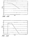
- Figures 10A, 10B , 10C and 10D illustrate the process of slowly turning down the voltage across the water valve.
- the numbers in these graphs are merely suggestive of actual numbers, and will vary depending on component values.
- the graph illustrates the voltage for point p2, which is at the node of the resistors R3 and R4 and the capacitor C1.
- Figure 10B is a graph of the voltage at out1.
- Figure 10C is a graph of the voltage at out2. Note that when the voltage at P2 decreases below 1.4 volts, there is insufficient voltage to saturate the transistors Q2 and Q3, and the voltage to the ports out1 and out2 is equal.
- the voltage across the ports out1 and out2 goes to zero when the voltage at point p2 decreases below 1.4 volts.
- the voltage alteration process applies full voltage across the valve to break the friction and start the valve moving and then decreases the voltage during the period that the valve is moving to minimize the power consumption.
- circuits can be used throughout the device to further limit the power consumption for other functions.
- the above power consumption units are used together. Any combination may be used, and a combination of all three power consumption units is contemplated.
- the voltage shaping circuit is used with either of the power control units. While the power control units have been described in relation to their operation to a flow controller for a hose, and in particular for controlling a valve, one of skill in the art will recognize that these power control units can be useful in any situation where the minimization of power consumption is desirable. This is true regardless of whether or not the receiver unit is powered by batteries or involves a flow controller.
- the apparatus further comprises a remote control 50, which is capable of communicating wirelessly with the electronics 40 of the flow controller 30, as described above.
- the remote control 50 includes a wireless transmitter and power source (preferably a battery 47).
- the system operates on radio frequency. In one preferred embodiment, frequencies in the range of 433MHz to 900 MHz are used. However, in other embodiments, infrared or other ranges of electromagnetic radiation can be employed.
- the transmitter operates off of a DC current with a preferred minimum range of 100 feet, more preferably with a minimum range of 200 feet.
- the remote controller 50 is mounted on the hose 16, particularly proximate the nozzle 22.
- the remote controller 50 can be mounted on the hose 16 by any suitable manner, including standard attachment bands 52 as illustrated.
- the flow controller 30 is placed between the faucet 10 and the nozzle 22 that terminates the distal end 20. However, rather than placing the flow controller 30 directly at the proximal end 18 of the hose line, the flow controller 30 is placed in an intermediate position along the hose line. Namely, the flow controller 30 is positioned between a first hose length or section 16a and a second hose length or section 16b. Additionally, the remote control 50 is shown freely held by a user's hand 54, rather than being mounted on the hose. As illustrated, the remote 50 can be very small, such as the remote controls sometimes found on key chains or as part of a key for automobile remote security control.
- FIG 3A illustrates the "key chain” remote control 50.
- the remote control 50 simply toggles the electrically actuated valve 38 ( Figure 1B ) between open and closed conditions.
- the remote control 50 includes manually operated controls for user operation.
- an "ON" button 58 represents the open condition for the electrically actuated valve 38 while an “OFF” button 59 represents the closed condition for this electrically actuated valve 38.
- a single button can serve to both open and close the electrically actuated valve 38, depending upon the current state of the valve when the signal is sent.
- either or both of the ON and OFF buttons can serve to partially open or partially close the valve along a continuum from the completely open state to the completely closed state.
- a single dial can similarly function to control the rate of flow by controlling the degree to which the electrically actuated valve 38 is open.
- a remote control 50 according to the invention with more complicated manual controls is illustrated.
- this remote control operates both the flow controller 30 as well as a hose reel mechanism for winding and/or unwinding hose onto/from a hose drum.
- the remote control 50 can operate the motor 114 of the embodiment of Figure 4 (described below).
- a single valve control button 62 is illustrated, such that pressing the button 62 will send a signal to the electronics 40 ( Figure 1B ) of the flow controller 30 to toggle the electrically actuated valve 38 between open and closed conditions.
- the valve control button 62 can be replaced by two buttons, as in Figure 3A , or can be replaced by any of the alternatives mentioned in the preceding paragraph.
- the remote control 50 of Figure 3B also includes one or more buttons for controlling hose reel operation.
- the remote control 50 includes a "stop" button 64, for halting the operation of the motor on the hose reel device, a "forward” button 66 for unwinding hose from the hose reel, and a “rewind” button 68 for winding hose onto the hose reel drum.
- a "stop" button 64 for halting the operation of the motor on the hose reel device
- a "forward” button 66 for unwinding hose from the hose reel
- a "rewind” button 68 for winding hose onto the hose reel drum.
- the "forward" button 66 can be omitted when the hose reel is arranged for manual unwinding, simply by pulling on the hose.
- a single button can be provided (in place of stop and rewind buttons) to toggle the hose reel motor between rewinding and off conditions.
- the associated electronics and the hose reel device can also be configured to conduct a short, timed rewind with a single quick tap upon the button, and to completely rewind the hose when the button is held down for a longer period of time.
- the skilled artisan will readily appreciate numerous modifications that can be made to the electronics to operate the flow controller and a hose reel device.
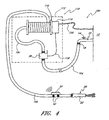
- a hose control apparatus 100 including a hose reel device 110, the flow controller 30 and the remote control 50, is illustrated.
- the first length of hose 16a conveys fluid from the fluid source or faucet 10 to the flow controller 30.
- the hose reel device 110 includes the flow controller 30 inside a hose reel housing 112, although in other arrangements the flow controller 30 can be connected outside the hose reel housing 112.
- the hose reel device 110 also includes a motor 114 for rotating a hose reel drum 116.
- a second hose section 16b wraps around the drum 116 and terminates at the distal end 20 in a hose nozzle 22 or attachment device, such as a spray gun or extension rod (not shown).
- the remote control 50 is attached at the distal end 20 of the hose, just upstream of the nozzle 22, by way of attachment bands 52 or other suitable means.
- the flow controller 30 is connected, directly or indirectly, upstream of the hose reel drum. Therefore, when the water is shut off at the flow controller 30, the second hose section 16b can be readily wrapped upon the drum 116 without the difficulties associated with water pressure within the second hose section 16b, despite the fact that the water spigot 14 is turned on and there is water pressure within the first hose section 16a.
- Fluid connection between the flow controller 30 and the second hose section 16b can be direct, but is preferably conducted via a third hose section 16c that leads to an integrated tubing and a further connection on the drum 116 between the integrated tubing and the second hose section 16b.
- a single command from the remote control both turns off the flow of water from the flow controller 30 and starts the hose reel device . 110 rewinding.
- One of the benefits of some of the herein described embodiments is that the combination of a remotely operated valve and remotely operated reel allows the benefits of the other device to be more fully exploited. For instance, as described above, the flow controller 30 allows the reel to more efficiently wind in and unwind the hose. Likewise, the advantage of the remote control for the reel allows one to fully enjoy the remote control aspect of the flow controller 30 since without it, if one were going to put the hose back, one would have to return to the original location of the hose.
- the flow controller 30 is also connected by way of the illustrated wire connection 118 to the hose reel motor 114, which is in turn connected to a power source, such as a relatively heavy duty rechargeable battery (not shown) or by the illustrated electrical cord 120 leading to an electrical source or outlet of the building 12.
- a power source such as a relatively heavy duty rechargeable battery (not shown) or by the illustrated electrical cord 120 leading to an electrical source or outlet of the building 12.
- the wire connection 118 can carry both electrical signals from the electronics 40 ( Figure 1B ), and power from the power source of the hose reel device 110 to the flow controller 30, thereby obviating a separate battery source for the flow controller 30.
- the wire connection 118 may comprise one or more wires. It will be understood that, by the illustrated wire connection 118, the flow controller 30 decodes and relays signals from the remote control 50 to operate the hose reel, as discussed above with respect to Figure 3B .
- the precise location of the electronics 40 need not be within the body of the flow controller 30.
- the electronics 40 including the wireless receiver 41, may be contained anywhere within the hose reel device 110 or within the hose reel housing 112, or even outside of or on top of the hose reel device. Indeed, in some embodiments, so long as the electronics 40 can communicate signals it receives to the flow controller 30, the electronics could practically be located anywhere.
- the important considerations to be made in deciding where to place the electronics 40 include those guiding principles pointed out in the present application, and those realized by one of ordinary skill in the art.
- the arrangement in Figure 4 has the benefit of placing one possible source of electricity, the electrical cord 120, at a significant distance from the inlet of the flow controller 30.
- This is advantageous because, when the electrically actuated valve 38 is closed, the inlet section of the flow controller 30 will still be experiencing the full pressure of substance in the hose. This inlet section of the closed flow controller 30 has a greater chance of leaking than the section of hose closer towards the nozzle. If the fluid is hazardous when combined with electricity (water or certain explosive gases, for example) it would be beneficial for the device to provide as much distance as possible between the primary source of electrical current and possible sources of leaks of the fluid.
- the electronics 40 are contained within the flow controller 30, in some embodiments it may be advantageous to place certain aspects of the electronics in other locations. For instance, it may be advantageous to place the wireless receiver(s) external to any hose reel housing 112, in order to allow for certain remote control devices to reach the receiver more readily. Alternatively, it may be desirable to limit the amount of electronics in the flow controller 30; thus, the electronics may be placed elsewhere and connected to the electrically activated valve 38 via a wire which will carry a signal to open or close the valve. In one embodiment, the electronics 40 are primarily contained within the hose reel device 110. In another embodiment, the electronics 40 are contained in or on the hose reel housing 112. In a preferred embodiment, the electronics 40 are primarily contained in the flow controller 30.
- the hose reel preferably includes a mechanism to distribute the hose across the surface of the drum 116 as it winds, thereby avoiding tangling and maximizing efficiency.
- the hose reel device 110 employs a mechanism similar to that disclosed in U.S. Patent No. 6,422,500 issued to Mead, Jr. on July 23, 2002 , and assigned to the assignee of the present application.
- that patent illustrates at Figures 8A and 8B and related text a method of distributing hose across the hose reel drum by relative rotation between a housing shell with a hose aperture and the drum housed within.
- Mechanisms for linking the rotation of the drum along the horizontal axis and the rotation of the surrounding shell can include the spiral groove as illustrated in the incorporated patent, or can include any of a number of other linkage systems.
- the hose reel device 110 and flow controller 30 can be connected to a water faucet 10 and placed at any convenient position.
- the second section of hose 16b is wound upon the hose reel drum 116 with perhaps only the nozzle 22 protruding from the hose reel housing 112.
- the flow controller 30 is preferably in an off position during non-use, such that there is less pressure in the second section of hose 16b during non-use than during use, although the spigot at the faucet 10 may be left open. There is thus minimum risk of leakage, at least upstream of the flow controller 30, and the hose section 16b readily winds upon the drum and can be slightly compressed, depending upon the nature of the hose.
- the pressure in section 16b may be increased, thus inflating the hose and assisting in the unwinding of the hose. This may be achieved by opening the electrically actuated valve, at least partially. As will be appreciated by one of skill in the art, in the embodiment described by Figure 4 , this pre-inflating of the hose may lead to water leaving the hose before the water is needed by the user. However, a second flow controller may be placed further downstream towards the nozzle 22, or manual controls may be in place at the nozzle as well.
- multiple flow controllers may be employed along a length of hose, for many reasons, the main two being that there may be multiple flow outlets, or because particular characteristics of hose properties may be desired in particular sections of a hose.
- the user can pull upon the nozzle 22 and freely unwind the hose from the drum 116.
- the motor 114 can be actuated (e.g., by use of the remote control 50) to automatically splay out and unwind the hose.
- the remote control 50 When the user has pulled the hose sufficiently and has reached a position where he would like to apply the fluid, the user employs the remote control 50 to open the flow control valve 38 in the flow controller 30. Since the spigot 14 is already open, there is no need to travel to the faucet 10, which may be difficult to reach or where there is likely to be muddiness from dripping water, in order to turn on the hose.
Landscapes
- Engineering & Computer Science (AREA)
- Water Supply & Treatment (AREA)
- Life Sciences & Earth Sciences (AREA)
- Environmental Sciences (AREA)
- Selective Calling Equipment (AREA)
- Storing, Repeated Paying-Out, And Re-Storing Of Elongated Articles (AREA)
- Application Of Or Painting With Fluid Materials (AREA)
- Forklifts And Lifting Vehicles (AREA)
- Extrusion Moulding Of Plastics Or The Like (AREA)
- Rigid Pipes And Flexible Pipes (AREA)
- Massaging Devices (AREA)
- Flexible Shafts (AREA)
- Magnetically Actuated Valves (AREA)
- Other Liquid Machine Or Engine Such As Wave Power Use (AREA)
Abstract
Description
- This invention relates generally to hose systems and more particularly to controlling fluid flow and reel operations of hose systems. The invention further relates to power saving aspects of the same.
- Hoses are typically used in conjunction with on/off valves positioned at a distal or proximal end of the hose. For example, garden hoses are fitted to a faucet on the outside of a house or other building, with a traditional manual spigot or valve for turning the water flow on or off at the faucet. Because the hose is designed to extend many yards away from the faucet, it is often convenient to have a means for turning the flow on or off at the distal or spray nozzle end of the hose. Thus, many manual devices such as spray guns are provided for fitting at the nozzle end of the hose so that the flow can be turned on or off without repeatedly returning to the faucet.
- Despite the availability of attachments for turning the flow on or off at the nozzle end, it is generally undesirable to leave the water flow on at the source when the hose is no longer in use. Continual water pressure along the entire length of the hose is undesirable for a number of reasons. The pressure tends to form leakage paths at joints between multiple lengths of hose, at the joint between the nozzle and the nozzle attachment (such as a spray gun), and at the joint between the faucet and the hose. Furthermore, continual pressure can also form leaks along the hose line itself. Constant leakage at these points leads to flooded or muddied garden areas, particularly near the faucet where the user has to go to turn the water on or off. Moreover, it is difficult to manipulate the hose, move it from place to place or coil the hose for storage with constant pressure along the hose line. This leads the user to turn off the water flow at the source, e.g., by the manual spigot on the outside faucet. However, it is often inconvenient to reach the faucet. Often the faucet is obstructed or difficult to reach and the area around the faucet tends to be muddied by water leakage.
- These problems have been addressed to some extent by providing a remotely controllable, electrically actuated valve or flow controller in the hose, the valve positioned to selectively open and close a fluid flow path through the hose via a remote control. However, there are power consumption issues that limit the use of remotely controlled devices. Remote control systems generally involve a remote transmitter powered by a battery, or low power source, and the unit to be controlled. The unit to be controlled is connected to a receiver that is usually powered by a continuous power source, lather than a battery. Thus, while the remote transmitter is typically powered by batteries and thus truly "wireless," the receiver is usually connected to a larger, or continuous, source of power by a wire. The reason the transmitter can operate from a battery, or low power source, is because a transmitter only needs to draw power when it transmits a wireless signal to the receiver, thus, the transmitter does not need to draw power at all times. On the other hand, the receiver cannot function in this way because it does not know when a command will be sent to it In other words, in traditional arrangements, the receiver must continuously monitor for incoming signals and, therefore, must be on at all times. The power that is needed to continuously monitor for an incoming signal would normally drain a battery in a few days. This makes a fully wireless, or battery-operated remotely controllable device, impractical.
- Such a hose control system, comprising a flow controller and a wireless remote control, is known from
US 6,283,139 B1 . - Motorized hose reels also exist. Such reels have mechanical and electrical controls on the reel itself.
- Accordingly, a need exists for improved control over fluid flow through a hose system, as well as over a motorized reel. A need also exists to reduce the power needed to operate this and other types of remote control systems for supplemental fluid flow controller and/or motorized reels. In satisfaction of these needs, the present application provides a hose control system according to
claim 1 that permits remote control of supplemental flow controllers and motorized reels for hose systems. - In one preferred embodiment, the present invention provides a hose control system comprising a flow controller, a hose reel device, electronic components, and a remote control. The flow controller includes an inlet, an outlet, a fluid flow path defined between the inlet and outlet, and an electrically actuated valve positioned to selectively close the fluid flow path. The hose reel device, which is in fluid communication with the outlet of the flow controller, comprises a rotatable drum onto which a hose can be spooled, and an electrical motor connected to rotate the drum. The electronic components are in communication with, and are configured to convey electrical power to drive, the valve and the motor. The electronic components comprise a wireless receiver configured to receive wireless command signals for controlling the valve and the motor. The remote control comprises manual controls and a wireless transmitter. The wireless transmitter is configured to transmit command signals to the wireless receiver for controlling the valve and the motor. The manual controls are connected to the wireless transmitter to permit control of the wireless transmitter.
- In another preferred aspect, the present invention provides a hose control system comprising a flow controller, a rotatable hose reel drum onto which a hose can be spooled, an electrically controllable motor connected to rotate the drum, electronic components, and a remote control. The flow controller has an inlet, an outlet, a fluid flow path defined between the inlet and outlet, and an electrically actuated valve positioned to selectively close the fluid flow path. The electronic components are in communication with the valve and the motor. The remote control is configured to transmit wireless command signals to the electronic components for controlling the valve and the motor.
- In another preferred aspect, the present invention provides a hose control system comprising a flow controller, a rotatable hose reel drum onto which a hose can be spooled, a motor connected to rotate the drum, a receiver, and a remote control. The flow controller has an inlet, an outlet, a fluid flow path defined between the inlet and outlet, and a valve positioned to selectively close the fluid flow path. The inlet is configured to mate with a residential water faucet, and the outlet is configured to mate with a water hose. The receiver is configured to receive wireless command signals for controlling the valve and the - motor. The remote control is configured to transmit wireless command signals to the receiver for controlling the valve and the motor.
- In another preferred aspect, the present invention provides a power savings system comprising a wireless receiver and a power control unit. The wireless receiver is configured to receive wireless signals for controlling at least one of an electrical motor driving rotation of a hose reel and an electrically actuated valve controlling a fluid flow through a hose system. The wireless receiver is capable of receiving the wireless signals only when the wireless receiver is in a powered state. The power control unit is configured to repeatedly switch the wireless receiver between powered and unpowered states in a cycle. In one embodiment, the power control unit is configured to keep the wireless receiver in its unpowered state for no more than a set time period during each cycle. In this embodiment, the system further comprises a remote control configured to transmit wireless command signals for controlling at least one of the motor and the valve, the remote control configured so that each signal is transmitted for a duration at least as long as the set time period.
- In another preferred aspect, the present invention provides a power savings system comprising a wireless receiver and a power control unit. The wireless receiver is configured to receive wireless signals for controlling at least one of an electrical motor driving rotation of a hose reel and an electrically actuated valve controlling a fluid flow through a hose system. The wireless receiver is capable of receiving the wireless signals only when the wireless receiver is in a powered state. The power control unit is configured to reduce power consumption by applying an initial voltage to initiate movement of a mechanical device and then reducing the voltage to the mechanical device after the mechanical device begins moving and before the mechanical device is intended to stop: In one embodiment the mechanical device is the valve. In another embodiment the mechanical device is the motor.
- In another aspect, the present invention provides the following method according to claim 27 : A wireless valve command signal is received for controlling an electrically actuated valve, the valve positioned to selectively close a fluid flow path through a hose system. The valve is positioned in response to the wireless valve command signal. A wireless reel command signal is received for controlling an electrical motor connected to rotate a drum onto which hose can be spooled. The motor is activated in response to the wireless reel command signal.
- In another aspect, the present invention provides the following method according to claim 38: A wireless valve command signal is transmitted from a remote control to a wireless receiver. Fluid flow through a hose system is controlled in accordance with the wireless valve command signal. A wireless reel command signal is transmitted from the remote control to the wireless receiver. An electric motor is controlled in accordance with the wireless reel command signal, the motor connected to rotate a rotatable reel drum onto which hose can be spooled.
- In another preferred aspect, the present invention provides a method of conserving power in the detection of a wireless signal from a remote transmitter. According to the method, a wireless receiver is repeatedly switched between powered and unpowered states in a cycle. The wireless receiver is configured to receive wireless signals for controlling at least one of an electrical motor driving rotation of a hose reel and an electrically actuated valve controlling a fluid flow through a hose system. The wireless receiver is capable of receiving the wireless signals only when the wireless receiver is in its powered state. If the wireless receiver receives a wireless signal while in its powered state, switching the wireless receiver to its unpowered state is ceased.
- In another preferred aspect, the present invention provides a power saving valve controller comprising a flow controller and electronic components in communication with the flow controller. The flow controller comprises an inlet, an outlet, a fluid flow path defined between the inlet and outlet, and an electrically actuated valve positioned to selectively close the fluid flow path. The electronic components comprise a wireless receiver configured to receive wireless command signals for controlling the valve, and a power control unit configured to repeatedly switch the wireless receiver between powered and unpowered states in a cycle.
- In another preferred aspect, the present invention provides a power saving valve controller comprising a flow controller and electronic components in communication with the flow controller. The flow controller comprises an inlet, an outlet, a fluid flow path defined between the inlet and outlet, and an electrically actuated valve positioned to selectively close the fluid flow path. The electronic components comprise a wireless receiver and a power control unit. The receiver is configured to receive wireless command signals for controlling the valve. The power control unit is configured to reduce power consumption by applying an initial voltage to initiate movement of the valve and reducing the voltage to the valve after the valve begins moving but before movement of the valve is intended to stop.
- In another preferred aspect, the present invention provides a method of reducing the power consumed by a flow controller. According to the method, a receiver is repeatedly switched on and off, the receiver being configured to receive wireless command signals for controlling an electrically actuated valve of the flow controller. If the receiver receives a wireless command signal, the receiver is kept on to allow the receiver to transmit the command signal to the electrically actuated valve.
- In another preferred aspect, the present invention provides a method of reducing the power consumed by a flow controller. According to the method, an electronic logic unit is kept in an unpowered state until a detection unit detects a wireless signal, the electronic logic unit being configured to receive the signal from the detection unit and process the signal to control a valve in the flow controller. The electronic logic unit is powered when the detection unit detects a wireless signal.
- In yet another preferred aspect, the present invention provides a method of reducing the power consumption of a system for controlling at least one of fluid flow in a hose system and a motor driving rotation of a reel drum for pooling a hose of the hose system. According to the method, an initial voltage is applied to initiate movement of a mechanical device. The initial voltage is reduced after the mechanical device begins moving but before the mechanical device is instructed to stop moving.
- For purposes of summarizing the invention and the advantages achieved over the prior art, certain objects and advantages of the invention have been described herein above. Of course, it is to be understood that not necessarily all such objects or advantages may be achieved in accordance with any particular embodiment of the invention. Thus, for example, those skilled in the art will recognize that the invention may be embodied or carried out in a manner that achieves or optimizes one advantage or group of advantages as taught herein without necessarily achieving other objects or advantages as may be taught or suggested herein.
- All of these embodiments are intended to be within the scope of the invention herein disclosed. These and other embodiments of the present invention will become readily apparent to those skilled in the art from the following detailed description of the preferred embodiments having reference to the attached figures, the invention not being limited to any particular preferred embodiment(s) disclosed.
-
-
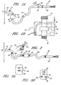
Figure 1A is a schematic illustration of a remotely controlled valve in accordance with a preferred embodiment. -
Figure 1B is a schematic cross-section of a flow controller constructed in accordance with a preferred embodiment. -
Figure 2 is a schematic illustration of a remotely controlled valve positioned between two lengths of hose and a remote control. The subject matter ofFigure 2 , without a reel, is outside the scope of the claims, and forms background explanation for the claimed matter. Certain embodiments may include aspects ofFigure 2 . -
Figure 3A schematically illustrates a remote control. The subject matter ofFigure 3A , without a reel, is outside the scope of the claims, and forms background explanation for the claimed matter. Certain embodiments may include aspects ofFigure 3A . -
Figure 3B schematically illustrates a remote control in accordance with another embodiment. -
Figure 4 schematically illustrates a system for remotely controlling fluid flow and reel operation in accordance with the invention. -
Figure 5 is a schematic representation of the electronics of one embodiment. -
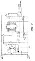
Figure 6 is an embodiment of a power control unit. -
Figure 7A is a graph of the voltage at theoutput pin 1 of the op-ampofFigure 6 . -
Figure 7B is the voltage at thenon-inverting input pin 3 ofFigure 6 . -
Figure 7C is the voltage at the inverting input pin 4 ofFigure 6 . -
Figure 8 is another embodiment of a power control unit. -
Figure 9 is another embodiment of a power control unit. -
Figure 10A is a graph that illustrates the voltage for point p2 ofFigure 9 . -
Figure 10B is a graph of the voltage at out1 ofFigure 9 . -
Figure 10C is a graph of the voltage at out2 ofFigure 9 . -
Figure 10D is a graph showing that the voltage across the ports out1 and out2 ofFigure 9 go to zero when the voltage at point p2 decreases below 1.4 volts - While illustrated in the context of garden hoses for household watering or washing applications, the skilled artisan will readily appreciate that the principles and advantages of the preferred embodiments are applicable to other types of hose products. For example, in addition to the illustrated liquid application, the fluid flow through the hose can comprise compressed air or vacuum suction for other applications.
-
Figure 1A illustrates one embodiment of the present invention. A fluid source is illustrated in the form of awater faucet 10 extending from the wall of abuilding 12. Thefaucet 10 includes a valve or spigot with amanual control 14. Ahose line 16 in communication with thefaucet 10 extends from aproximal end 18 to adistal end 20, terminating in anozzle 22. Thenozzle 22 is conventionally configured to receive attachments. Preferably, the nozzle receives a manually actuated nozzle attachment (not shown), such as a spray gun. - A
flow controller 30 is positioned at some point between thedistal end 20 of thehose line 16 and thewater faucet 10. Theflow controller 30, shown in more detail inFigure 1B , defines afluid flow path 32 from aninlet 34 to anoutlet 36. Desirably, theinlet 34 is configured with internal threading to receive the external threads of a conventional faucet outlet. Similarly, theflow controller outlet 36 defines external threads of a standard diameter and pitch to receive the internal threads of a conventional garden hose connection. Along, theflow path 32 an electrically actuatedvalve 38, such as a solenoid valve, for example, selectively permits or inhibits flow therethrough. Such electrically actuated valves with inlets and outlets are known in commercially available sprinkler timing systems. If the term "supplemental" is used to describe theflow controller 30, the flow controller may still be the only controller in the system. In other words, the term "supplemental" is not necessarily meant to suggest that there must be other means of controlling the flow; rather, the term is used as an aid to distinguish this flow controller over other items, such as themanual control 14. - In the illustrated embodiments (
Figures 1A, 1B ,4 , and5 ), theflow controller 30 includeselectronics 40 configured to receive and communicate signals, or command signals, from a remote source such as a transmitter or remote control 50 (Figures 1A, 3B ,4 and5 ). Thus, theelectronics 40 aided by anantenna 42, include a wireless receiver configured to receive electromagnetic signals from a remote source, and to translate those signals into signals that may open or close the electrically actuatedvalve 38. Additionally, as shown inFigure 4 , theflow controller 30 may be linked, via one ormore wires 118, to amotor 114 that drives rotation of areel drum 116. Thus, theflow controller 30 can send signals to control the operation of themotor 114 for the reel, the motor command signals being conveyed to the motor via thewire connection 118. The wire connection can also convey power to one or both of theflow controller 30 and themotor 114. In the illustrated embodiment, themotor 114 is powered by connection of anelectrical plug 120 to a power supply, thewire connection 118 conveying power to theflow controller 30. Examples of communication methods include infrared (IR) and radio frequency (RF) communications. - As illustrated in
Figure 5 , thewireless receiver 41 will comprise some type ofdetection unit 44, such as an RF receiver integrated circuit (IC) chip, configured to detect incoming wireless signals. Additionally, thereceiver 41 may comprise a logio unit orcircuit 43, which is configured to analyse and decode incoming wireless signals detected by thedetection unit 44 and determine what, if any, response should be generated. Thereceiver 41 is preferably configured to communicate, electrically, with an electrically driven device, in order that the electrical signals can be converted into a physical change, such as the actuation of a valve, for example. Thedetection unit 44 and thelogic unit 43 need not be physically located within a single housing orreceiver 41. - Note that, while illustrated as an external component,
antenna 42 the antenna can alternatively be incorporated within the housing of theflow controller 30. Also illustrated inFigure 1B is a self-contained DC power source in the form of batteries 47. It will be understood that theflow controller 30 can alternatively be powered by AC current from an electrical outlet on thebuilding 12, or by solar cells or the like. - In another embodiment, the logic unit will be external to the receiver. This logic unit could be an Application-Specific Integrated Circuit (ASIC), or a standard IC decoder unit. The logic unit can preferably be powered down when it is not needed.
- Additionally, as shown in
Figure 5 , theelectronics 40 may include a "power control unit" that lowers the power consumption of thereceiver 41. Thepower control unit 45 may be especially valuable when thereceiver 41 is powered by batteries 47. As explained above in the Background section, a conventional wireless receiver consumes a great deal of power because the receiver must continually monitor for wireless commands. If the receiver is powered by batteries, the battery power would be exhausted in a very short period of time, such as a week or less Thepower control unit 45 overcomes this limitation. In one embodiment, of thepower control unit 45, thereceiver 41 may function for up to six months. In one embodiment, the power control unit may allow a receiver to function for up to twenty times longer than a receiver without the power control unit. - In one embodiment, the
power control unit 45 generally operates by shutting down thedetection unit 44 of thereceiver 41, and all other electronics for a "reasonable response time." A "reasonable response time" means a time period that a user would not notice or mind in the operation of theremote control transmitter 50. In another embodiment, a "reasonable response time" is defined as slightly shorter than the duration that the signal from the remote control transmitter lasts 50. For example, when activation of thetransmitter 50 results in a signal that lasts 3 seconds, then the shut down time on thedetection unit 44 is preferably less than 3 seconds. In alternative embodiments, the shut down time of thedetection unit 44 is longer than the duration of the signal from thetransmitter 50 In these embodiments, the transmitted signal may not be detected by thedetection unit 44, which could cause more substantial wait times. In an alternative embodiment, the reasonable response time factors in the fact that some of the embodiments are as a water hose operated device, for which a user may be willing to wait several seconds before anything occurs at the user's location. In an alternative embodiment, a reasonable response time is a time period determined by the necessary life of the battery and the power currently in the battery. For example, if the battery, or batteries, should last for a years worth of continuous use in thereceiver 41, but the batteries only supply 1 week's worth of continuous activity for thedetector unit 44, then thepower control unit 45 will only activate the detector unit approximately 1 second out of every 52 seconds. A 51 second down cycle could result in a very long delay between the initiation of the signal from thetransmitter 50 to any flow of water through thehose 16, but this is merely an example of how the time periods could be set. However, thedetector unit 44 needs only a fraction of a second to determine if a signal is being received. For example, thedetector unit 44 could be on for 1/50 of a second, or 20 milliseconds, during each second. This would be a sufficient time to recognize if a signal is being received and would save a significant amount of power. - Once the
power control unit 45 powers up thedetection unit 44, the detection unit searches for a signal. This process of repeatedly shutting on and off thedetection unit 44, as well as other current draining equipment, limits the amount of power needed for continuously monitoring for incoming wireless signals. If thedetection unit 44 does not detect a signal within a set amount of time, thepower control unit 45 preferably turns off the power to the detection unit for another period of time, thus repeating a cycle. - In another embodiment, the
power control 45 unit also turns off thelogic unit 43. Thelogic unit 43 need not be automatically turned back on after a certain period of time. Instead, powering on thelogic unit 43 on is only required when a wireless signal is detected by thedetection unit 44. In one embodiment, this signal is a valid command from theremote transmitter 50 to open or close thevalve 38 or activate themotor 114. - In either of these power saving embodiments, the device can be configured to return to its power saving mode after a wireless signal has been detected and the signal ceases. That is, while the detection of a signal results in the
power control unit 45 allowing the device to use more power, the end of a signal may also allow the power control unit to return theelectronics 40 to their low power consumption state. In some embodiments it may be desirable to include a delay following the cessation of the signal, in case another signal is likely to follow. For example, it may be efficient to leave theelectronics 40 fully operational, even after a signal to close thevalve 38 has stopped being transmitted, as it may be likely that a signal to rewind the hose reel is soon to follow. - In one aspect, the
power control unit 45 employs an op-amp to switch thedetection unit 44 on and off, repeatedly, in order to conserve battery life. - A preferred embodiment of a power control unit can be seen in
Figure 6 . The power control unit preferably comprises a very low power bi-stable oscillator. The oscillator comprises an op-amp U1A, a plurality of resistors R1, R2, R3, R4 and R5, a capacitor C1, and a diode D1. The op-amp U1A has anon-inverting input pin 3, an inverting input pin 4, and anoutput pin 1, among others. Resistors R1, R2, and R3 form a voltage divider, which provides one of two voltages to thenon-inverting input pin 3 of the op-amp U1A. The resistor R3 provides hysteresis to stabilize the op-amp. While the receiver is an RF receiver in this embodiment, other communications methods could also be used in place of RF communications.Figures 7A, 7B , and7C illustrate the voltages at the pins of the op-amp.Figure 7A is the voltage at theoutput pin 1 of the op-amp.Figure 7B is the voltage at thenon-inverting input pin 3, andFigure 7C is the voltage at the inverting input pin 4. - The voltage at
non-inverting pin 3 is higher when the voltage at theoutput pin 1 is high because of the effects of the voltage divider. The capacitor C1 charges, gradually increasing the voltage at the inverting pin 4 until the voltage equals the voltage of thenon-inverting pin 3. The op-amp U1A then changes the output ofpin 1 to its low voltage, Vol. Because there are no capacitors connected to thenon-inverting pin 3, and thus no time delay, the low output onpin 1 immediately reduces the voltage to pin 3. The low output voltage also causes current to flow though the resistors R4 and R5 and lowers the voltage across the capacitor C1. Voltage across a capacitor cannot change immediately, so the voltage at the inverting input 4 gradually decreases. When the voltage at pin 4 decreases to the voltage of thenon-inverting pin 3 theoutput pin 1 of the op-amp U1A rises to the op-amp's high voltage, Voh. The high output of theoutput pin 1 causes current to flow though the resistor R4 and raises the voltage across the capacitor C1. As the capacitor charges, the voltage at the inverting input pin 4 increases. When the voltage at the inverting pin 4 equals the voltage of thenon-inverting pin 3, theoutput pin 1 switches to Vol, thus repeating a continuous cycle. The non-inverting duration (Tp) is proportional to the time constant determined by the resistance of resistor R4 multiplied by the capacitance of capacitor C1. The inverting duration (Tn) is proportional to the time constant of the combined resistance of resistors R3 and R4 in parallel multiplied by the capacitance of capacitor C1. This time constant is defined as ((R4*R3)/(R4 + R3))*C1. - When the
output pin 1 of op-amp U1A is high, a transistor Q1 has no base current and does not conduct. This turns the power off to the RF receiver U2. When theoutput pin 1 of the op-amp U1A is low, the transistor Q1 has base current conducting through the resistor R6 and turns on such that the voltage at the collector of the transistor Q1 is close to the voltage of Battery+. This turns the power on to the RF receiver U2. As described above, Tn, the time that the RF receiver U2 receives power, is proportional to the time constant. In a preferred embodiment, Tn is 1/20 of the total cycle time, Tn + Tp. Preferably, the RF receiver is on between about 2% and 20% of each cycle, more preferably between about 3% and 10%. The on and off duration can be further modified by making the resistors R1 and R2 unequal to form an additional voltage divider. - The RF receiver U2 outputs a signal on the
data pin 10 if there is a RF command being received. When the output ofdata pin 10 is high, current conducts through a diode D2, charging the capacitor C2. When the voltage across the capacitor C2 is above 0.6 volts, current conducts through a resistor R8 and the base-emitter junction of a transistor Q2. When current conducts through the base-emitter junction of the transistor Q2, the transistor Q2 turns on and the voltage at the collector is close to ground. This causes current to flow through a resistor R7 and the transistor Q1 base-emitter junction thus holding the transistor Q1 in the on state, applying power to the RF receiver U2. This performs the function of applying power to the RF receiver U2 while the command is decoded and executed. In this embodiment, the RF receiver U2 receives the RF data and also decodes it. When the RF reciver no longer is receiving a signal, thedata pin 10 goes low and the control of power to the RF receiver U2 is restored to the bi-stable oscillator. - When the RF receiver U2 has decoded a command it outputs the results on data pin D0,
pin 2 of RF receiver U2, and/or data pin D1,pin 3 of the RF receiver U2. If the function1 port is to be enabled, then the RF receiver U2 outputs a high voltage on the data pin D0 (pin 2). If the function0 port is to be enabled it outputs a high voltage on the data pin D1 (pin 3). A high voltage on the data pin D0 (pin 2) will cause current to flow through the diode D4 and pull the enable function1 port to a high voltage. A high voltage on the data pin D1 (pin 3) will cause current to flow through the diode D3 and pull the enable function0 port to a high voltage. In another embodiment of a power control unit seen infigure. 8 , the power control unit preferably comprises an op-amp U1A, a plurality of resistors R1, R2, R3, R4 and R5, and a capacitor C1 to form a very low power bi-stable oscillator similar to the embodiment above. - When the
output pin 1 of the op-amp U1A is high, a transistor Q1 has no base current and does not conduct. This turns the power off to a RF receiver U2. In this embodiment, the RF receiver U2 serves only as a receiver. The RF receiver U2 passes the data to an ASIC U3 for decoding as seen inFigure 8 . When theoutput pin 1 of the op-amp U1 is low, the transistor Q1 has base current conducting through the resistor R6 and turns on such that the voltage at the collector is close to Battery+. The high collector voltage turns the power on to the RF receiver U2. - The output of the RF receiver U2 on data pin 8 is used to maintain power to the RF receiver U2 while the command is being received. The RF receiver U2 outputs a signal on data pin 8 if there is an RF command being received. When the output on the data pin 8 is high, current conducts through the diode D2, charging the capacitor C2. When the voltage across the capacitor C2 is above 0.6 volts, current conducts through a resistor R8 and the base-emitter junction of a transistor Q2. The transistor Q2 turns on and the voltage at the collector is close to ground. This causes current to flow through a resistor R7 and the transistor Q1 base-emitter junction. Thus, the transistor Q1 is held in the on state, applying power to the RF receiver U2 while the command is decoded.
- The output of the RF receiver U2 on data pin 8 is also used to maintain power to the ASIC U3 while the command is being decoded. When the voltage across the capacitor C2 is above 0.6 volts, current conducts through a resistor R11 and the base-emitter junction of a transistor Q3. The transistor Q3 turns on and the voltage at the collector is close to ground. This causes current to flow through a resistor R12 and the transistor Q3 base - emitter junction thus holding a transistor Q4 in the on state, applying power to the ASIC U3. When the ASIC U3 has decoded a command it and determines that the command is a valid command, it outputs a high voltage on the function enable port which turns the power on to the electronics to implement the appropriate functions. The data pin 8 of the RF receiver U2 is turned off, and the power cycle is restored to the control of the bi-stable oscillator.
- In another embodiment illustrated in
Figure 9 , the power control unit alters the voltage that is being applied across a valve operating device for the period of time required to open or close the valve. In one embodiment, the power control unit applies a constant voltage across the valve for a period of time sufficient to overcome the initial friction of the valve in order to start the valve moving. Then, the power control valve decreases the voltage for the next period of time while the valve is moving. This process lowers the total amount of energy needed to open or close the valve. When the user presses the switch S1, the anode of a diode D1 is connected to Battery +. The diode D1 will go into conduction and the voltage at the cathode of diode D1 will rise to the "breakover" voltage of the diode (e.g., 0.6 volts). Similarly, when the voltage at enablefunction 0 goes high, a diode D2 will go into conduction and the voltage at the cathode of the diode D2 will rise to 0.6 volts. When voltage at the cathode of either diode D1 or D2 is high, the voltage across a capacitor C1 changes. The voltage across the capacitor C1 cannot change instantaneously, so current flows through a resistor R4 and the emitter-base junction of a transistor Q1. The transistor Q1 turns on and saturates the collector-emitter junction voltage. Current flows through a resistor R5 and the emitter-base junction of a transistor Q2. Additionally, current flows through a resistor R6 and the emitter-base junction of a transistor Q3. This current is initially enough to saturate Q2 and Q3, thus effectively connecting Out1 and Out 2 to Battery+ and Battery- respectively. - As the capacitor C1 charges, the voltage across the resistor R4 decreases. When the transistor Q1 is no longer saturated, the current through the resistors R5 and R6 will fall, which will cause the transistors Q2 and Q3 to no longer be saturated. The voltage at out1 will slowly drop from Battery+ and the voltage at out2 will slowly increase from battery-. This effectively decreases the voltage between out1 and out2, which is the voltage across the water valve. As the voltage across the valve decreases, the power which is consumed by the valve decreases. When the transistors Q1, Q3, and Q4 are turned off, the power is disconnected from the valve.
-
Figures 10A, 10B ,10C and 10D illustrate the process of slowly turning down the voltage across the water valve. The numbers in these graphs are merely suggestive of actual numbers, and will vary depending on component values. InFigure 10A , the graph illustrates the voltage for point p2, which is at the node of the resistors R3 and R4 and the capacitor C1.Figure 10B is a graph of the voltage at out1.Figure 10C is a graph of the voltage at out2. Note that when the voltage at P2 decreases below 1.4 volts, there is insufficient voltage to saturate the transistors Q2 and Q3, and the voltage to the ports out1 and out2 is equal. As illustrated inFigure 10D , the voltage across the ports out1 and out2 goes to zero when the voltage at point p2 decreases below 1.4 volts. The voltage alteration process applies full voltage across the valve to break the friction and start the valve moving and then decreases the voltage during the period that the valve is moving to minimize the power consumption. - Similar circuits can be used throughout the device to further limit the power consumption for other functions. In a preferred embodiment, there is a circuit for each function enable setting.
- In one embodiment, several of the above power consumption units are used together. Any combination may be used, and a combination of all three power consumption units is contemplated. In one embodiment, the voltage shaping circuit is used with either of the power control units. While the power control units have been described in relation to their operation to a flow controller for a hose, and in particular for controlling a valve, one of skill in the art will recognize that these power control units can be useful in any situation where the minimization of power consumption is desirable. This is true regardless of whether or not the receiver unit is powered by batteries or involves a flow controller.
- Referring again to
Figure 1A , the apparatus further comprises aremote control 50, which is capable of communicating wirelessly with theelectronics 40 of theflow controller 30, as described above. Accordingly theremote control 50 includes a wireless transmitter and power source (preferably a battery 47). In one embodiment, the system operates on radio frequency. In one preferred embodiment, frequencies in the range of 433MHz to 900 MHz are used. However, in other embodiments, infrared or other ranges of electromagnetic radiation can be employed. Preferably, the transmitter operates off of a DC current with a preferred minimum range of 100 feet, more preferably with a minimum range of 200 feet. In the illustrated embodiment, theremote controller 50 is mounted on thehose 16, particularly proximate thenozzle 22. Theremote controller 50 can be mounted on thehose 16 by any suitable manner, includingstandard attachment bands 52 as illustrated. - Referring now to
Figure 2 , the system for controlling flow is illustrated. The subject matter ofFigure 2 , without a reel, is outside the scope of the claims, and forms background explanation for the claimed matter. Theflow controller 30 is placed between thefaucet 10 and thenozzle 22 that terminates thedistal end 20. However, rather than placing theflow controller 30 directly at theproximal end 18 of the hose line, theflow controller 30 is placed in an intermediate position along the hose line. Namely, theflow controller 30 is positioned between a first hose length orsection 16a and a second hose length orsection 16b. Additionally, theremote control 50 is shown freely held by a user's hand 54, rather than being mounted on the hose. As illustrated, the remote 50 can be very small, such as the remote controls sometimes found on key chains or as part of a key for automobile remote security control. -
Figure 3A illustrates the "key chain"remote control 50. In this simple example, theremote control 50 simply toggles the electrically actuated valve 38 (Figure 1B ) between open and closed conditions. Theremote control 50 includes manually operated controls for user operation. In the illustrated example, an "ON"button 58 represents the open condition for the electrically actuatedvalve 38 while an "OFF"button 59 represents the closed condition for this electrically actuatedvalve 38. It will be understood that, in other arrangements, a single button can serve to both open and close the electrically actuatedvalve 38, depending upon the current state of the valve when the signal is sent. In a more complicated arrangement, either or both of the ON and OFF buttons can serve to partially open or partially close the valve along a continuum from the completely open state to the completely closed state. A single dial can similarly function to control the rate of flow by controlling the degree to which the electrically actuatedvalve 38 is open. - With reference now to
Figure 3B , aremote control 50 according to the invention with more complicated manual controls is illustrated. As will be better understood fromFigure 4 and related text below, this remote control operates both theflow controller 30 as well as a hose reel mechanism for winding and/or unwinding hose onto/from a hose drum. For example, theremote control 50 can operate themotor 114 of the embodiment ofFigure 4 (described below). In this arrangement, a singlevalve control button 62 is illustrated, such that pressing thebutton 62 will send a signal to the electronics 40 (Figure 1B ) of theflow controller 30 to toggle the electrically actuatedvalve 38 between open and closed conditions. It will be understood that thevalve control button 62 can be replaced by two buttons, as inFigure 3A , or can be replaced by any of the alternatives mentioned in the preceding paragraph. - The
remote control 50 ofFigure 3B also includes one or more buttons for controlling hose reel operation. In the illustrated embodiment, theremote control 50 includes a "stop" button 64, for halting the operation of the motor on the hose reel device, a "forward"button 66 for unwinding hose from the hose reel, and a "rewind"button 68 for winding hose onto the hose reel drum. Note the use of symbols on these buttons to mimic standard symbols on tape, compact disc, and video playback devices. In other arrangements, it will be understood that the "forward"button 66 can be omitted when the hose reel is arranged for manual unwinding, simply by pulling on the hose. Additionally, in such an arrangement a single button can be provided (in place of stop and rewind buttons) to toggle the hose reel motor between rewinding and off conditions. The associated electronics and the hose reel device can also be configured to conduct a short, timed rewind with a single quick tap upon the button, and to completely rewind the hose when the button is held down for a longer period of time. The skilled artisan will readily appreciate numerous modifications that can be made to the electronics to operate the flow controller and a hose reel device. - With reference now to
Figure 4 , a hose control apparatus 100, including a hose reel device 110, theflow controller 30 and theremote control 50, is illustrated. The first length ofhose 16a conveys fluid from the fluid source orfaucet 10 to theflow controller 30. In the illustrated embodiment, the hose reel device 110 includes theflow controller 30 inside ahose reel housing 112, although in other arrangements theflow controller 30 can be connected outside thehose reel housing 112. As illustrated, the hose reel device 110 also includes amotor 114 for rotating ahose reel drum 116. Asecond hose section 16b wraps around thedrum 116 and terminates at thedistal end 20 in ahose nozzle 22 or attachment device, such as a spray gun or extension rod (not shown). As shown, theremote control 50 is attached at thedistal end 20 of the hose, just upstream of thenozzle 22, by way ofattachment bands 52 or other suitable means. - Preferably, the
flow controller 30 is connected, directly or indirectly, upstream of the hose reel drum. Therefore, when the water is shut off at theflow controller 30, thesecond hose section 16b can be readily wrapped upon thedrum 116 without the difficulties associated with water pressure within thesecond hose section 16b, despite the fact that thewater spigot 14 is turned on and there is water pressure within thefirst hose section 16a. Fluid connection between theflow controller 30 and thesecond hose section 16b can be direct, but is preferably conducted via athird hose section 16c that leads to an integrated tubing and a further connection on thedrum 116 between the integrated tubing and thesecond hose section 16b. In one embodiment, a single command from the remote control both turns off the flow of water from theflow controller 30 and starts the hose reel device . 110 rewinding. One of the benefits of some of the herein described embodiments is that the combination of a remotely operated valve and remotely operated reel allows the benefits of the other device to be more fully exploited. For instance, as described above, theflow controller 30 allows the reel to more efficiently wind in and unwind the hose. Likewise, the advantage of the remote control for the reel allows one to fully enjoy the remote control aspect of theflow controller 30 since without it, if one were going to put the hose back, one would have to return to the original location of the hose. - The
flow controller 30 is also connected by way of the illustratedwire connection 118 to thehose reel motor 114, which is in turn connected to a power source, such as a relatively heavy duty rechargeable battery (not shown) or by the illustratedelectrical cord 120 leading to an electrical source or outlet of thebuilding 12. Note that thewire connection 118 can carry both electrical signals from the electronics 40 (Figure 1B ), and power from the power source of the hose reel device 110 to theflow controller 30, thereby obviating a separate battery source for theflow controller 30. Thewire connection 118 may comprise one or more wires. It will be understood that, by the illustratedwire connection 118, theflow controller 30 decodes and relays signals from theremote control 50 to operate the hose reel, as discussed above with respect toFigure 3B . It will be understood by one of skill in the art that, in some embodiments, the precise location of theelectronics 40 need not be within the body of theflow controller 30. For instance, theelectronics 40, including thewireless receiver 41, may be contained anywhere within the hose reel device 110 or within thehose reel housing 112, or even outside of or on top of the hose reel device. Indeed, in some embodiments, so long as theelectronics 40 can communicate signals it receives to theflow controller 30, the electronics could practically be located anywhere. The important considerations to be made in deciding where to place theelectronics 40 include those guiding principles pointed out in the present application, and those realized by one of ordinary skill in the art. For example, the arrangement inFigure 4 has the benefit of placing one possible source of electricity, theelectrical cord 120, at a significant distance from the inlet of theflow controller 30. This is advantageous because, when the electrically actuatedvalve 38 is closed, the inlet section of theflow controller 30 will still be experiencing the full pressure of substance in the hose. This inlet section of theclosed flow controller 30 has a greater chance of leaking than the section of hose closer towards the nozzle. If the fluid is hazardous when combined with electricity (water or certain explosive gases, for example) it would be beneficial for the device to provide as much distance as possible between the primary source of electrical current and possible sources of leaks of the fluid. - While in many embodiments, the
electronics 40 are contained within theflow controller 30, in some embodiments it may be advantageous to place certain aspects of the electronics in other locations. For instance, it may be advantageous to place the wireless receiver(s) external to anyhose reel housing 112, in order to allow for certain remote control devices to reach the receiver more readily. Alternatively, it may be desirable to limit the amount of electronics in theflow controller 30; thus, the electronics may be placed elsewhere and connected to the electrically activatedvalve 38 via a wire which will carry a signal to open or close the valve. In one embodiment, theelectronics 40 are primarily contained within the hose reel device 110. In another embodiment, theelectronics 40 are contained in or on thehose reel housing 112. In a preferred embodiment, theelectronics 40 are primarily contained in theflow controller 30. - While not illustrated, it will be understood that the hose reel preferably includes a mechanism to distribute the hose across the surface of the
drum 116 as it winds, thereby avoiding tangling and maximizing efficiency. Most preferably, the hose reel device 110 employs a mechanism similar to that disclosed inU.S. Patent No. 6,422,500 issued to Mead, Jr. on July 23, 2002 , and assigned to the assignee of the present application. In particular, that patent illustrates atFigures 8A and 8B and related text a method of distributing hose across the hose reel drum by relative rotation between a housing shell with a hose aperture and the drum housed within. Mechanisms for linking the rotation of the drum along the horizontal axis and the rotation of the surrounding shell can include the spiral groove as illustrated in the incorporated patent, or can include any of a number of other linkage systems. - In operation, the hose reel device 110 and flow
controller 30 can be connected to awater faucet 10 and placed at any convenient position. When not in use, the second section ofhose 16b is wound upon thehose reel drum 116 with perhaps only thenozzle 22 protruding from thehose reel housing 112. Theflow controller 30 is preferably in an off position during non-use, such that there is less pressure in the second section ofhose 16b during non-use than during use, although the spigot at thefaucet 10 may be left open. There is thus minimum risk of leakage, at least upstream of theflow controller 30, and thehose section 16b readily winds upon the drum and can be slightly compressed, depending upon the nature of the hose. In another embodiment, while there is little pressure insection 16b of the hose while the hose is not being used, in order to assist the unwinding of the hose, the pressure insection 16b may be increased, thus inflating the hose and assisting in the unwinding of the hose. This may be achieved by opening the electrically actuated valve, at least partially. As will be appreciated by one of skill in the art, in the embodiment described byFigure 4 , this pre-inflating of the hose may lead to water leaving the hose before the water is needed by the user. However, a second flow controller may be placed further downstream towards thenozzle 22, or manual controls may be in place at the nozzle as well. - In one embodiment, multiple flow controllers may be employed along a length of hose, for many reasons, the main two being that there may be multiple flow outlets, or because particular characteristics of hose properties may be desired in particular sections of a hose.
- When it is desired to operate the hose, the user can pull upon the
nozzle 22 and freely unwind the hose from thedrum 116. In other arrangements, themotor 114 can be actuated (e.g., by use of the remote control 50) to automatically splay out and unwind the hose. When the user has pulled the hose sufficiently and has reached a position where he would like to apply the fluid, the user employs theremote control 50 to open theflow control valve 38 in theflow controller 30. Since thespigot 14 is already open, there is no need to travel to thefaucet 10, which may be difficult to reach or where there is likely to be muddiness from dripping water, in order to turn on the hose. Nor does water flow freely during such a special trip to thefaucet 10 between the time of turning on the faucet and returning to the nozzle, even in the situation where no manually actuated nozzle attachment is used. Rather, the user is already in position and holding the nozzle when the water flow is actuated. Furthermore, the user need not return to thefaucet 10 in order to shut the water off, but would rather simply use theremote control 50 to shut the water flow off at theflow controller 30. - As appreciated by one of skill in the art, in some embodiments, the particular arrangements described above result in situations in which the chance the fluid flowing through the hose, coming into contact with any electrical current, is greatly reduced. However, it may still be beneficial to effectively seal many of the components that use electricity in order to further reduce any risk.
- It will be appreciated by those skilled in the art that various omissions, additions, and modifications may be made to the methods and structures described above without departure from the scope of the invention. All such modifications and changes are intended to fall within the scope of the invention, as defined by the appended claims.
Claims (38)
- A hose control system, comprising:a flow controller (30) having an inlet (34), an outlet (36), a fluid flow path (32) defined between the inlet and outlet, and an electrically actuated valve (38) positioned to selectively close the fluid flow path;a hose reel device (110) comprising a rotatable hose reel onto which a hose (16) can be spooled, wherein said hose reel device (110) is in fluid communication with the outlet (36) of the flow controller (30) and the hose (16b) is at least partially spooled on said hose reel;an electrically controllable motor (114) connected to rotate the reel;electronic components (40) in communication with said valve (38) and said motor (114); anda wireless remote control (50) configured to transmit wireless command signals to the electronic components (40) for controlling the valve (38) and the motor (114), wherein the wireless remote control (50) is mounted proximate a distal end (20) of the hose (16).
- The hose control system of Claim 1, wherein the electronic components (40) in communication with said valve (38) and said motor (114) comprise a wireless receiver (41) configured to receive the wireless command signals for controlling the valve and the motor, the electronic components being configured to convey electrical power to drive the valve and the motor, and wherein the wireless remote control (50) comprises manual controls (62,64;66,68) and a wireless transmitter, the wireless transmitter being configured to transmit the command signals to the wireless receiver (41) for controlling the valve and the motor, the manual controls being connected to the wireless transmitter to permit control of the wireless transmitter.
- The hose control system of Claim 2, wherein the wireless receiver (41) is integrated with the flow controller (30).
- The hose control system of Claim 2, wherein the electronic components (40) include integrated circuit (IC) chips.
- The hose control system of Claim 2, wherein the wireless receiver (41) is a radio frequency (RF) receiver.
- The hose control system of Claim 2, wherein the electronic components (40) further comprise an electronic logic unit (43) configured to receive the wireless command signals from the wireless receiver (41) and process said command signals to control the valve (38) and the motor (114).
- The hose control system of Claim 6, wherein the logic unit (43) comprises an IC decoder unit.
- The hose control system of Claim 2, wherein the electronic components (40) are configured to position the valve (38) at any of a plurality of positions between a completely closed position in which the fluid flow path (32) is completely closed and a completely open position in which the fluid flow path is completely open.
- The hose control system of Claim 2, wherein the inlet (34) of the flow controller (30) is configured to mate with an outlet of a water faucet (10), the outlet being configured to mate with a hose.
- The hose control system of Claim 2, wherein the inlet (34) and the outlet (36) of the flow controller (30) are configured to mate with ends of hose sections (16a,16c).
- The hose control system of Claim 2, wherein the hose reel device (110) and the flow controller (30) are positioned within a common housing (112).
- The hose control system of Claim 2, wherein the manual controls (62,64,66,68) of the wireless remote control (50) comprise one or more motor controls (64,66,68) for transmitting command signals to the wireless receiver (41) for controlling the motor (114), and one or more valve controls (62) for transmitting command signals to the wireless receiver (41) for controlling the valve (38).
- The hose control system of Claim 1, wherein the inlet (34) is configured to mate with a residential water faucet (10), the outlet (36) being configured to mate with a water hose (16).
- The hose control system of Claim 2, wherein the wireless receiver (41) is capable of receiving the wireless command signals only when the wireless receiver is in a powered state, and wherein the hose control system further comprises a power control unit (45) configured to repeatedly switch the wireless receiver (41) between powered and unpowered states in a cycle.
- The hose control system of Claim 14, wherein the power control unit (45) keeps the wireless receiver (41) in its powered state between about 2-20% of the time of the cycle.
- The hose control system of Claim 15, wherein the power control unit (45) keeps the wireless receiver (41) in its powered state between about 3-10% of the time of the cycle.
- The hose control system of Claim 14, wherein the wireless receiver (41) comprises a detection unit (44) configured to detect and receive the wireless command signals and an electronic logic unit (43) configured to receive the command signals from the detection unit, the logic unit being further configured to process said command signals to control at least one of the motor (114) and the valve (38), wherein the power control unit (45) is configured to keep the logic unit (43) in an unpowered state until the wireless receiver receives a wireless signal.
- The hose control system of Claim 14, wherein the power control unit (45) comprises an operational amplifier.
- The hose control system of Claim 14, wherein the wireless receiver (41) comprises a radio frequency (RF) receiver.
- The hose control system of Claim 14, wherein the power control unit (45) is configured to keep the wireless receiver (41) in its unpowered state for no more than a set time period during each cycle, the wireless remote control (50) being configured to transmit the wireless command signals such that each signal is transmitted for a duration at least as long as said set time period.
- The hose control system of Claim 2, wherein said electronic components (40) further comprise:the wireless receiver (41) configured to receive the wireless command signals from the wireless remote control (50) only when the wireless receiver is in a powered state; anda power control unit (45) configured to reduce power consumption by applying an initial voltage to initiate movement of a mechanical device and then reducing the voltage to the mechanical device after the mechanical device begins moving and before the mechanical device is intended to stop.
- The hose control system of Claim 21, wherein the mechanical device is the valve (38).
- The hose control system of Claim 21, wherein the mechanical device is the motor (114).
- The hose control system of Claim 2, wherein the electronic components (40) further comprise:the wireless receiver (41) configured to receive the wireless command signals for controlling the valve (38); anda power control unit (45) configured to repeatedly switch the wireless receiver (41) between powered and unpowered states in a cycle.
- The hose control system of Claim 24, further comprising an electronic logic unit (43) configured to process said signals, wherein the power control unit (45) is configured to keep the electronic logic unit (43) in an unpowered state until the wireless receiver (41) receives a wireless command signal, the power control unit (45) being configured to switch the electronic logic unit (43) to a powered state after the receiver (41) receives the wireless command signal.
- The hose control system of Claim 1, wherein the reel comprises a drum (116).
- A method comprising:receiving a wireless valve command signal for controlling an electrically actuated valve (38), the valve being positioned to selectively close a fluid flow path (32) through a hose (16);positioning the valve (38) in response to the wireless valve command signal;receiving a wireless reel command signal for controlling an electrical motor (114) connected to rotate a reel onto which the hose (16) can be spooled; andactivating the motor (114) in response to the wireless reel command signal;wherein said wireless command signals originate from a wireless remote control (50) that is mounted proximate a distal end (20) of the hose (16).
- The method of Claim 27, further comprising:repeatedly switching a wireless receiver (41) between powered and unpowered states in a cycle, the wireless receiver being capable of receiving the wireless valve command and reel command signals only when the wireless receiver is in its powered state; andif the wireless receiver (41) receives a wireless signal while in its powered state, ceasing to switch the wireless receiver to its unpowered state.
- The method of Claim 28, further comprising keeping the wireless receiver (41) in its powered state between about 2-20% of the time of the cycle.
- The method of Claim 29, further comprising keeping the wireless receiver (41) in its powered state between about 3-10% of the time of the cycle.
- The method of Claim 28, further comprising:keeping an electronic logic unit (43) in an unpowered state, the electronic logic unit (43) being configured to receive command signals from the wireless receiver (41) and process said signals to control at least one of the motor (114) and the valve (38); andif the wireless receiver (41) receives a wireless signal, switching the logic unit (43) to a powered state.
- The method of Claim 28, wherein the wireless valve command and reel command signals are each transmitted for a duration at least as long as a set time period, the method further comprising:keeping the wireless receiver (41) in its unpowered state for no more than said set time period during each cycle.
- The method of Claim 27, further comprising:repeatedly switching on and off a receiver (41) configured to receive the wireless command signals for controlling the valve (38) or the motor (114); andif the receiver (41) receives a wireless command signal, keeping the receiver on to allow the receiver to transmit the command signal to the valve (3 8) or motor (114).
- The method of Claim 27, further comprising:keeping an electronic logic unit (43) in an unpowered state until a detection unit (44) detects the wireless valve command signal or the wireless reel command signal, the electronic logic unit being configured to receive the signal from the detection unit and process said signal to control the valve (38) or the motor (114); andpowering the electronic logic unit (43) when the detection unit (44) detects one of the wireless signals.
- The method of Claim 27, further comprising:when one of the wireless command signals is received, applying an initial voltage to initiate movement of a mechanical device; andreducing said initial voltage after the mechanical device begins moving but before the mechanical device is intended to stop moving.
- The method of Claim 35, wherein the mechanical device is the valve (38) positioned to selectively close the fluid flow path (32) through the hose (16).
- The method of Claim 35, wherein the mechanical device is the motor (114) driving rotation of the reel.
- A method comprising:transmitting a wireless valve command signal from a wireless remote control (50) to a wireless receiver (41);controlling fluid flow through a hose (16) in accordance with the wireless valve command signal by positioning an electrically actuated valve (38) in response to the wireless valve command signal;transmitting a wireless reel command signal from the wireless remote control (50) to the wireless receiver (41);controlling an electric motor (114) in accordance with the wireless reel command signal, the motor being connected to rotate a rotatable reel onto which the hose (16) can be spooled;wherein said wireless remote control (50) is mounted proximate a distal end (20) of the hose (16);repeatedly switching the wireless receiver (41) between powered and unpowered states in a cycle, the wireless receiver being capable of receiving the wireless valve command and reel command signals only when the wireless receiver is in its powered state; andif the wireless receiver (41) receives a wireless signal while in its powered state, ceasing to switch the wireless receiver to its unpowered state.
Applications Claiming Priority (3)
| Application Number | Priority Date | Filing Date | Title |
|---|---|---|---|
| US45522903P | 2003-03-13 | 2003-03-13 | |
| US455229P | 2003-03-13 | ||
| PCT/US2004/007953 WO2004080161A1 (en) | 2003-03-13 | 2004-03-12 | Remote control for hose operation |
Publications (2)
| Publication Number | Publication Date |
|---|---|
| EP1601245A1 EP1601245A1 (en) | 2005-12-07 |
| EP1601245B1 true EP1601245B1 (en) | 2011-02-23 |
Family
ID=32990937
Family Applications (1)
| Application Number | Title | Priority Date | Filing Date |
|---|---|---|---|
| EP20040737327 Expired - Lifetime EP1601245B1 (en) | 2003-03-13 | 2004-03-12 | Remote control for hose operation |
Country Status (16)
| Country | Link |
|---|---|
| US (3) | US7503338B2 (en) |
| EP (1) | EP1601245B1 (en) |
| JP (2) | JP2006520207A (en) |
| CN (2) | CN101595823A (en) |
| AT (1) | ATE498999T1 (en) |
| AU (1) | AU2004220468B2 (en) |
| BR (1) | BRPI0408250A (en) |
| CA (2) | CA2709852C (en) |
| DE (1) | DE602004031507D1 (en) |
| DK (1) | DK1601245T3 (en) |
| ES (1) | ES2359815T3 (en) |
| HK (1) | HK1090254A1 (en) |
| MX (1) | MXPA05009774A (en) |
| NZ (1) | NZ542701A (en) |
| RU (1) | RU2371748C2 (en) |
| WO (1) | WO2004080161A1 (en) |
Families Citing this family (80)
| Publication number | Priority date | Publication date | Assignee | Title |
|---|---|---|---|---|
| BRPI0408250A (en) | 2003-03-13 | 2006-03-01 | Great Stuff Inc | energy-saving hose control systems, energy-saving valve controllers, and operating, energy-saving, and energy-saving methods consumed by a flow controller and a control system |
| CN101891088A (en) * | 2004-07-01 | 2010-11-24 | 巨杰公司 | Be used to promote the automatic reel of the winding of linear material |
| US7419038B2 (en) | 2005-05-31 | 2008-09-02 | Great Stuff, Inc. | Reel and reel housing |
| DE102005042701A1 (en) * | 2005-09-01 | 2007-03-08 | Torras-Piqué, Jorge | Arrangement to control water flow in irrigating installation fed by water supply connected to pump has device which produces control signal emitted as radio signal to switch on of off water supply to feed pump |
| US20070126591A1 (en) * | 2005-12-02 | 2007-06-07 | Robertshaw Controls Company | Washing Machine Water Leak Prevention System |
| TW200848347A (en) | 2007-02-23 | 2008-12-16 | Great Stuff Inc | Remote control for valve and hose reel system |
| US7950379B2 (en) * | 2007-07-27 | 2011-05-31 | Advanced Launch Corporation | High velocity mass accelerator and method of use thereof |
| US7921871B2 (en) * | 2007-09-14 | 2011-04-12 | Lawrence John E | Low-profile, less conspicuous retractable garden hose reel |
| US8439651B2 (en) * | 2009-07-14 | 2013-05-14 | Briggs & Stratton Corporation | Garden hose booster water pump system |
| US8485796B2 (en) | 2009-03-25 | 2013-07-16 | Briggs & Stratton Corporation | Booster water spraying system |
| US8499369B2 (en) * | 2009-03-31 | 2013-08-06 | Shervin Shokouh Ahmady | Tank water conservation system |
| US8245985B2 (en) * | 2009-04-24 | 2012-08-21 | Robert Bosch Gmbh | Hose hanger device |
| US7931225B2 (en) * | 2009-05-20 | 2011-04-26 | Hsin-Fa Wang | Water hose winding device |
| EP2499409A1 (en) * | 2009-11-11 | 2012-09-19 | Michael Librus | Remote-controlled, water dispensing system |
| US9032565B2 (en) | 2009-12-16 | 2015-05-19 | Kohler Co. | Touchless faucet assembly and method of operation |
| US8336800B1 (en) * | 2010-01-20 | 2012-12-25 | Lopez John D | Powered hose reel device |
| US8662856B2 (en) * | 2010-02-17 | 2014-03-04 | Akron Brass Co. | Pump control system |
| KR20130038246A (en) * | 2010-03-18 | 2013-04-17 | 그라코 미네소타 인크. | Adjusting pump flow at tool |
| KR20130006482A (en) * | 2010-03-22 | 2013-01-16 | 그라코 미네소타 인크. | Rf control module for continuous feed drywall tools |
| US10232395B2 (en) | 2010-07-19 | 2019-03-19 | Irrigreen, Inc. | Multi-nozzle rotary sprinkler |
| US8878397B2 (en) | 2010-08-31 | 2014-11-04 | Great Stuff, Inc. | Electrical cord reel with control system to limit overheating |
| BE1019479A3 (en) | 2010-09-08 | 2012-07-03 | Alpha Reel Bvba | MOTORIZED HOSE Reel. |
| US8418773B2 (en) | 2010-09-10 | 2013-04-16 | Jason Cerrano | Fire-fighting control system |
| US9027903B2 (en) * | 2010-12-15 | 2015-05-12 | Autosplice, Inc. | Power-efficient actuator assemblies and methods of manufacture |
| US8695912B2 (en) | 2011-04-19 | 2014-04-15 | Great Stuff, Inc. | Reel systems and methods for monitoring and controlling linear material slack |
| US9623271B2 (en) | 2011-05-10 | 2017-04-18 | Rom Acquisition Corporation | Fire hose deployment device |
| CN102826415A (en) * | 2011-06-14 | 2012-12-19 | 张春宇 | Power line winder |
| US8995099B2 (en) | 2011-08-05 | 2015-03-31 | Great Stuff, Inc. | Control system for electrical cord reel |
| CN103782479B (en) * | 2011-08-31 | 2016-04-20 | 株式会社东芝 | Power supply forgets closing detecting apparatus, power supply is forgotten to close detection method and detection system |
| US8770504B1 (en) * | 2011-09-23 | 2014-07-08 | Thomas Sandstrom | Motor driven fishing reel |
| CN104040871B (en) | 2011-10-26 | 2016-11-16 | 奥图斯普公司 | Memory alloy actuation equipment and manufacture thereof and using method |
| US8771005B2 (en) | 2011-12-30 | 2014-07-08 | Great Stuff, Inc. | Electrical cord with wear ring |
| US8801458B2 (en) | 2012-01-03 | 2014-08-12 | Great Stuff, Inc. | Electrical cord reel with removeable cord |
| US9295862B2 (en) * | 2012-01-19 | 2016-03-29 | Jason Cerrano | Fire-fighting system |
| US20130214059A1 (en) * | 2012-02-17 | 2013-08-22 | Briggs & Stratton Corporation | Water spraying system |
| US9051927B2 (en) | 2012-02-17 | 2015-06-09 | Briggs & Stratton Corporation | Water pump having two operating conditions |
| US20140021284A1 (en) | 2012-07-20 | 2014-01-23 | Great Stuff, Inc. | Reel with manually actuated retraction system |
| US8814531B2 (en) | 2012-08-02 | 2014-08-26 | Briggs & Stratton Corporation | Pressure washers including jet pumps |
| DE202013100435U1 (en) * | 2012-09-11 | 2013-02-13 | Ipek International Gmbh | System for video data transmission in pipelines |
| US20140261766A1 (en) * | 2013-03-12 | 2014-09-18 | Great Stuff, Inc. | Hose reel assembly |
| US20150027565A1 (en) * | 2013-07-23 | 2015-01-29 | Pairoj Vatanakorn | Water supply monitor |
| JP2016532202A (en) * | 2013-08-16 | 2016-10-13 | ハスクバーナ・アーベー | Intelligent site management system |
| US10130962B2 (en) * | 2013-10-10 | 2018-11-20 | Briggs & Stratton Corporation | Wirelessly controlled trigger start and chemical tank change-over for pressure washers |
| US9049821B1 (en) * | 2014-01-10 | 2015-06-09 | John Nashed Hanna | Water flow control system |
| DE102014200312A1 (en) * | 2014-01-10 | 2015-07-16 | Autoliv Development Ab | Reversible belt tensioner |
| US10870135B2 (en) | 2014-12-05 | 2020-12-22 | Briggs & Stratton, Llc | Pressure washers including jet pumps |
| GB2538504C2 (en) * | 2015-05-18 | 2024-02-28 | Exel Industries Sa | Garden watering controllers |
| JP6580922B2 (en) * | 2015-09-28 | 2019-09-25 | 株式会社タカギ | Sprinkler |
| US9958084B2 (en) * | 2016-01-16 | 2018-05-01 | Elkhart Brass Manufacturing Company, Inc. | Valve actuator |
| US10758933B2 (en) | 2016-03-01 | 2020-09-01 | Carlisle Fluid Technologies, Inc. | Fluid regulation system |
| US20180236498A1 (en) * | 2016-03-30 | 2018-08-23 | Nlb Corp. | Clutch for high-pressure pump |
| JP6739786B2 (en) * | 2016-05-30 | 2020-08-12 | 武蔵エンジニアリング株式会社 | Liquid material discharge device, coating device and coating method thereof |
| CN105993855B (en) * | 2016-07-08 | 2022-03-04 | 山东农业大学 | Mobile micro-sprinkling irrigation water and fertilizer integrated comprehensive management system and management and control method thereof |
| US10618086B2 (en) * | 2016-07-18 | 2020-04-14 | Milwaukee Electric Tool Corporation | Drain cleaner with feed handle |
| EP3526149A4 (en) | 2016-10-17 | 2020-05-06 | Great Stuff, Inc. | Pivotable reel assembly |
| US20180126401A1 (en) * | 2016-11-10 | 2018-05-10 | MMLJ, Inc | Safety Button System and Method of Use |
| US10472202B2 (en) | 2016-11-10 | 2019-11-12 | Acme Product Development, Ltd. | System and method for a powered vertical axis hose reel |
| DE202016106612U1 (en) * | 2016-11-28 | 2018-03-02 | Rehau Ag + Co | Irrigation system, especially for terraces and balconies |
| CN107278834A (en) * | 2017-08-10 | 2017-10-24 | 石台县余节高苦槠农产品有限公司 | A kind of agricultural drip irrigation controller |
| US10865511B2 (en) | 2017-11-15 | 2020-12-15 | Haier Us Appliance Solutions, Inc. | Nozzle assembly for a washing machine appliance |
| CN108223890A (en) * | 2018-02-13 | 2018-06-29 | 施才军 | It is remotely controlled bidet |
| WO2019204814A1 (en) * | 2018-04-20 | 2019-10-24 | Realmfive, Inc. | Full livestock system |
| CN110479007A (en) * | 2018-05-15 | 2019-11-22 | 合肥硕森科技有限公司 | A kind of pressure vessel hydraulic-seal dust cleaning apparatus based on smoke pipe monitoring |
| CN108812222B (en) * | 2018-07-11 | 2020-09-22 | 浙江华疆科技有限公司 | Household balcony plant watering equipment |
| KR102127870B1 (en) * | 2019-03-14 | 2020-06-29 | 주식회사 한진지티씨 | Air hose supply for life saving |
| US11603654B2 (en) | 2019-05-15 | 2023-03-14 | Milwaukee Electric Tool Corporation | Drain cleaning device |
| US11325826B2 (en) * | 2019-11-08 | 2022-05-10 | Booster Fuels, Inc. | Refueling vehicle |
| US11753272B2 (en) * | 2019-12-10 | 2023-09-12 | Gary Morrison | Mobile reel carrier |
| US11121562B2 (en) * | 2019-12-23 | 2021-09-14 | Jeff W H Li | System for automated charging management |
| US11225394B1 (en) * | 2020-03-03 | 2022-01-18 | Nathan Cooper | Motorized hose reel |
| CN111252631B (en) * | 2020-03-24 | 2024-08-09 | 士商(湖州)精密技术有限公司 | Intelligent electric winder and control method thereof |
| CA3176796A1 (en) | 2020-04-28 | 2021-11-04 | James B.A. Tracey | Reel unwinding and winding control |
| US12042043B2 (en) | 2020-06-11 | 2024-07-23 | Kohler Co. | Temperature tracking mirror |
| CN111747244B (en) * | 2020-07-08 | 2022-05-24 | 徐蕊 | New energy automobile fills electric pile based on electromagnetic induction principle |
| US11685630B2 (en) * | 2020-09-15 | 2023-06-27 | Timothy Robert Havens | Outdoor hose storage enclosure |
| US20230080355A1 (en) * | 2021-09-15 | 2023-03-16 | Thrive Smart Systems Incorporated | Battery cassette system |
| CN114194956A (en) * | 2021-10-20 | 2022-03-18 | 南通碧兰宇环保科技有限公司 | Intelligent retraction device for ship shore power cable |
| CN114001188B (en) * | 2021-11-24 | 2024-04-09 | 杭州老板电器股份有限公司 | Fluid tap |
| KR102432723B1 (en) * | 2022-03-11 | 2022-08-18 | 주식회사 비바엔에스 | Apparatus and the method for the bare ground type wireless automatic irrigating |
| CN117303136B (en) * | 2023-11-28 | 2024-02-13 | 北京中宏联工程技术有限公司 | Cable winding and unwinding device |
Family Cites Families (169)
| Publication number | Priority date | Publication date | Assignee | Title |
|---|---|---|---|---|
| US561384A (en) * | 1896-06-02 | fletcher | ||
| US2276714A (en) * | 1941-06-06 | 1942-03-17 | Louie A Brown | Fluid motor |
| US2518990A (en) * | 1948-04-06 | 1950-08-15 | Wayne H Keener | Fluid actuated hose reel |
| US2621870A (en) * | 1950-01-16 | 1952-12-16 | American Marsh Pumps Inc | Hose reel assembly |
| US2607360A (en) * | 1951-02-01 | 1952-08-19 | Young Jack | Water-powered reel for washing |
| US2898605A (en) * | 1955-07-13 | 1959-08-11 | Raymond C Pearson | Water powered retractable showerhead |
| US2963227A (en) * | 1958-06-06 | 1960-12-06 | Symington Wayne Corp | Device for remotely winding a reel |
| US3011469A (en) * | 1958-09-10 | 1961-12-05 | Falkner Dallas Jay | Water ski rope retriever |
| US3471885A (en) * | 1966-06-15 | 1969-10-14 | John Mcloughlin | Hydro driven hose washer and winder |
| US3910497A (en) * | 1971-11-01 | 1975-10-07 | Rockwell International Corp | Hydraulic valve operator and remote control |
| US3810487A (en) * | 1971-11-22 | 1974-05-14 | Porta Service Inc | Mobile lubrication apparatus |
| US3786869A (en) | 1972-04-27 | 1974-01-22 | Loughlin J Mc | Nozzle pressure control system |
| US3911955A (en) * | 1974-03-29 | 1975-10-14 | Gustav A Link | Sprinkler control system |
| US3939862A (en) * | 1974-05-22 | 1976-02-24 | Edward E. Brondyke | Hose reel |
| US3943312A (en) | 1975-02-14 | 1976-03-09 | Grumman Aerospace Corporation | Fire hose nozzle coupler switch |
| US3974879A (en) | 1975-02-14 | 1976-08-17 | Grumman Aerospace Corporation | Method and apparatus for delivering constant water flow rates to a fire hose at each of a plurality of selectable flow rate settings |
| US4101873A (en) | 1976-01-26 | 1978-07-18 | Benjamin Ernest Anderson | Device to locate commonly misplaced objects |
| US4012002A (en) | 1976-05-19 | 1977-03-15 | Fmc Corporation | Automatic coupling mechanism for hose reels |
| US4276482A (en) * | 1977-06-03 | 1981-06-30 | Otis Engineering Corporation | Line flow electric power generator |
| DE2836415A1 (en) * | 1977-08-22 | 1979-03-08 | Solar Product Promotions Pty L | WATER FLOW REGULATING DEVICE |
| US4142367A (en) * | 1977-10-17 | 1979-03-06 | Eleanor A. Guisti Dondero | Domestic water pressure-flow powered generator system |
| US4186881A (en) * | 1978-11-09 | 1980-02-05 | Long Mfg. N. C., Inc. | Irrigation machine |
| US4276900A (en) * | 1979-08-02 | 1981-07-07 | Lars Rosenqvist | Irrigation device |
| US4333490A (en) * | 1980-01-04 | 1982-06-08 | Enter Sr William L | Apparatus and method for controlling a watering system |
| EP0035892A3 (en) | 1980-03-06 | 1982-04-21 | Heatrae-Sadia Heating Limited | Fluid flow control |
| US4352025A (en) * | 1980-11-17 | 1982-09-28 | Troyen Harry D | System for generation of electrical power |
| US4588318A (en) * | 1980-12-22 | 1986-05-13 | Black & Decker Inc. | Painting applicator with remote transmitter control |
| US4396149A (en) * | 1980-12-30 | 1983-08-02 | Energy Management Corporation | Irrigation control system |
| US4392063A (en) * | 1981-03-23 | 1983-07-05 | Voest-Alpine Aktiengesellschaft | Turbine installation comprising a turbine installed in a duct |
| SU1087120A1 (en) | 1981-10-09 | 1984-04-23 | Всесоюзное Научно-Производственное Объединение По Механизации Орошения "Радуга" | Hose-type automatic sprinkler |
| AT372577B (en) * | 1982-03-04 | 1983-10-25 | Bauer Roehren Pumpen | MOBILE SPRINKLING DEVICE FOR SPRINKLING AGRICULTURAL AREAS |
| US4488055A (en) * | 1982-03-10 | 1984-12-11 | James Toyama | Fluid pipe generator |
| US4513772A (en) | 1983-07-25 | 1985-04-30 | Richard Fisher | Automatic hose reel |
| US4858827A (en) | 1984-01-30 | 1989-08-22 | L. R. Nelson Corporation | Electronic water sprinkler timer |
| US4533835A (en) * | 1984-03-15 | 1985-08-06 | Sterling Beckwith | Control apparatus for hydraulically driven generator |
| US4572228A (en) * | 1984-12-24 | 1986-02-25 | Cherne Industries, Inc. | Connector valve assembly for inflatable packer device |
| FR2582876B1 (en) * | 1985-06-04 | 1988-11-18 | Kaeser Charles | PORTABLE HYDROELECTRIC GENERATOR GROUP |
| DE3532511A1 (en) | 1985-09-12 | 1986-09-11 | Hugo Brennenstuhl GmbH & Co KG, 7400 Tübingen | PARTICULARLY PORTABLE DRUM FOR RECEIVING A BENDABLE MEDIUM OR. POWER PIPE LIKE COMPRESSED AIR HOSE, WATER HOSE, ELECTRIC CABLE OR THE LIKE. |
| US4839039B2 (en) * | 1986-02-28 | 1998-12-29 | Recurrent Solutions Ltd | Automatic flow-control device |
| US4731545A (en) * | 1986-03-14 | 1988-03-15 | Desai & Lerner | Portable self-contained power conversion unit |
| JPS62173222U (en) | 1986-04-25 | 1987-11-04 | ||
| JPS61257123A (en) * | 1986-05-19 | 1986-11-14 | ヤンマー農機株式会社 | Irrigation apparatus for growing seedling |
| US4845418A (en) * | 1986-08-27 | 1989-07-04 | Allen-Bradley Company, Inc. | Flux profile control for startup of an induction motor |
| US4730637A (en) * | 1987-02-20 | 1988-03-15 | White F Grove | Fluid loss, damage prevention and control system |
| JPS63234924A (en) * | 1987-03-24 | 1988-09-30 | 東陶機器株式会社 | Shower apparatus |
| US4830283A (en) * | 1987-06-10 | 1989-05-16 | Johnson Bradford H | Irrigation system |
| FR2618910B1 (en) * | 1987-07-28 | 1989-10-27 | Inst Francais Du Petrole | METHOD AND DEVICE FOR IMPROVING THE COEFFICIENT OF TRANSMISSION TO GEOLOGICAL FORMATIONS OF ENERGY CREATED BY A SEISMIC WELL SOURCE |
| US4832074A (en) | 1988-05-26 | 1989-05-23 | Li Wen Kuang | Automatic water hose rewinder |
| JPH0278329A (en) * | 1988-06-24 | 1990-03-19 | Toshiba Corp | Selective call receiver and method for string and transferring identification code used therefor |
| US4852802A (en) * | 1988-08-08 | 1989-08-01 | Jerry Iggulden | Smart irrigation sprinklers |
| US5249631A (en) * | 1989-05-24 | 1993-10-05 | Bran Ferren | Water powered mobile robot |
| US5078476A (en) * | 1989-06-30 | 1992-01-07 | Goldstar Co. Ltd. | Automatic backlight on/off control apparatus for liquid crystal display television |
| US5134347A (en) | 1991-02-22 | 1992-07-28 | Comfortex Corporation | Low power consumption wireless data transmission and control system |
| EP0509151A1 (en) | 1991-04-17 | 1992-10-21 | C.I.P.A. - S.R.L. | Drive unit for rotary drum sprinkler irrigation devices |
| US5332322A (en) | 1991-06-06 | 1994-07-26 | Gambaro Thomas L | Ergonomic thumb-actuable keyboard for a hand-grippable device |
| JP2917594B2 (en) | 1991-07-18 | 1999-07-12 | 富士通株式会社 | Cache control unit |
| US5390206A (en) * | 1991-10-01 | 1995-02-14 | American Standard Inc. | Wireless communication system for air distribution system |
| US5391962A (en) * | 1992-07-13 | 1995-02-21 | The United States Of America As Represented By The Secretary Of The Army | Electron beam driven negative ion source |
| US5381962A (en) | 1992-12-10 | 1995-01-17 | Hydro-Chem Systems, Inc. | Remote controlled spraying device |
| US5383605A (en) | 1992-12-10 | 1995-01-24 | Hydro-Chem Systems, Inc. | Radio controlled spraying device |
| ES2123755T3 (en) * | 1993-01-14 | 1999-01-16 | Phoenix Ag | WATERPROOFING PROFILE FOR TUBULAR TUNNEL SEGMENTS, ESPECIALLY FOR ELEMENTS FLOATLY POSITIONED IN THEIR POSITION. |
| US5445176A (en) * | 1993-03-22 | 1995-08-29 | Goff; Milton L. | Moisture sensitive irrigation valve control |
| CA2093715A1 (en) * | 1993-04-08 | 1994-10-09 | Garry Workhoven | Vacuum hose storage and access apparatus for a central vacuum cleaning system |
| JPH072362U (en) * | 1993-06-16 | 1995-01-13 | 株式会社丸山製作所 | Hose winding / delivery device |
| JP2585087Y2 (en) * | 1993-10-14 | 1998-11-11 | 宇呂電子工業株式会社 | Automatic cleaning device |
| US5760706A (en) * | 1993-10-29 | 1998-06-02 | Kiss; Michael Z. | Remote control system using partially earth-buried RF antenna |
| JPH07132251A (en) * | 1993-11-09 | 1995-05-23 | Keiji Bando | Uniform liquid distribution and spraying method and device therefor |
| US5465904A (en) * | 1993-12-03 | 1995-11-14 | Vaello; Donald B. | Domestic watering and agricultural irrigation control system |
| US5495995A (en) * | 1994-01-31 | 1996-03-05 | Reelcraft Industries, Inc. | Motor driven hose reel |
| US5870302A (en) * | 1994-02-17 | 1999-02-09 | Waterlink Systems, Inc. | Evapotranspiration remote irrigation control system |
| AU1700495A (en) * | 1994-02-17 | 1995-09-04 | Waterlink Systems, Inc. | Evapotranspiration forecasting irrigation control system |
| US5445178A (en) * | 1994-02-18 | 1995-08-29 | Feuer; Lenny | Soil moisture sensor |
| US5427350A (en) * | 1994-05-31 | 1995-06-27 | Rinkewich; Isaac | Electrically-operated control valve and water distribution system including same |
| US5881775A (en) | 1994-10-24 | 1999-03-16 | Hexcel Corporation | Heat exchanger tube and method for making |
| DE19502148C2 (en) * | 1995-01-25 | 2003-08-28 | Grohe Armaturen Friedrich | Control for a sanitary fitting |
| US5549262A (en) | 1995-06-06 | 1996-08-27 | Suncast Corporation | Hose guide |
| AUPN414895A0 (en) | 1995-07-14 | 1995-08-03 | National Valve & Engineering Company Pty. Limited | Fuelling system |
| US5740031A (en) * | 1995-09-07 | 1998-04-14 | Smart Rain Corp. Inc. | Control system for the irrigation of watering stations |
| US5568824A (en) * | 1995-09-19 | 1996-10-29 | Cordrey; Michael P. | Hose reel |
| US5647388A (en) * | 1995-11-13 | 1997-07-15 | Phytotronics, Inc. | Misting and watering system controller with light sensistive detector |
| US5715866A (en) | 1995-12-29 | 1998-02-10 | Granger; Melforde A. | Portable fluid dispensing apparatus |
| JP3948031B2 (en) | 1996-02-26 | 2007-07-25 | 松下電工株式会社 | Condition setting device for control circuit of watering machine |
| JPH09286570A (en) | 1996-04-24 | 1997-11-04 | Tohoku Maruyama Kk | Hose winding device |
| US5749521A (en) * | 1996-05-22 | 1998-05-12 | Lore Parker | Moisture sensing electronic irrigation control |
| JP3713328B2 (en) * | 1996-05-31 | 2005-11-09 | 株式会社共立 | Hose feed and take-up device |
| JPH09322664A (en) * | 1996-06-07 | 1997-12-16 | Towa Kinzoku Kyodo Kumiai | Controller for feed of fluid |
| US5793174A (en) | 1996-09-06 | 1998-08-11 | Hunter Douglas Inc. | Electrically powered window covering assembly |
| US5813655A (en) * | 1996-10-11 | 1998-09-29 | Pinchott; Gordon A. | Remote-control on/off valve |
| GB9623713D0 (en) | 1996-11-14 | 1997-01-08 | Hartley Brian | Semi-automatic electric cable extension reel |
| CA2235634A1 (en) | 1997-04-23 | 1998-10-23 | Peter J. Stouffer | Communications system |
| AR003907A1 (en) * | 1997-06-05 | 1998-09-30 | Rosenfeld Bernardo Raul | AUTONOMOUS ECOLOGICAL IRRIGATION SYSTEM |
| JP2001510900A (en) * | 1997-07-18 | 2001-08-07 | コーラー、カンパニー | Radar equipment for low power applications and bathroom equipment |
| DE19737721A1 (en) | 1997-08-29 | 1999-03-04 | Gardena Kress & Kastner Gmbh | Device for program-controlled execution of a function |
| DE19742038A1 (en) * | 1997-09-24 | 1999-03-25 | Wabco Gmbh | Solenoid valve state detection method |
| US5927603A (en) * | 1997-09-30 | 1999-07-27 | J. R. Simplot Company | Closed loop control system, sensing apparatus and fluid application system for a precision irrigation device |
| USD405071S (en) | 1997-10-17 | 1999-02-02 | Gambaro Thomas L | Cursor control--data entry device |
| US5947148A (en) * | 1998-01-07 | 1999-09-07 | Devito; Robert | Fluid delivery hose recovery system |
| US6337635B1 (en) * | 1998-01-31 | 2002-01-08 | Orbit Irrigation Products, Inc. | Remotely controllable programmable hose faucet valve system |
| US5975162A (en) * | 1998-04-02 | 1999-11-02 | Link, Jr.; Clarence J. | Liquid delivery vehicle with remote control system |
| US6144840A (en) * | 1998-04-13 | 2000-11-07 | Advanced Micro Devices, Inc. | Wireless telephone ring detection method for extended battery life |
| US6453215B1 (en) * | 1998-04-14 | 2002-09-17 | Nathan Lavoie | Irrigation controller |
| BE1011896A3 (en) * | 1998-04-29 | 2000-02-01 | Reels Besloten Vennootschap Me | Improved hose reel. |
| US6452499B1 (en) * | 1998-10-07 | 2002-09-17 | Thomas Henry Runge | Wireless environmental sensor system |
| US5957253A (en) * | 1998-10-13 | 1999-09-28 | Clanton; Rocky Lee | Stationary motorized power cord reel |
| US6236850B1 (en) * | 1999-01-08 | 2001-05-22 | Trw Inc. | Apparatus and method for remote convenience function control with increased effective receiver seek time and reduced power consumption |
| US6257264B1 (en) * | 1999-01-25 | 2001-07-10 | Sturman Bg, Llc | Programmable electronic valve control system and methods of operation thereof |
| US6206050B1 (en) | 1999-03-31 | 2001-03-27 | Certainteed Corporation | Hose used to install loose fill insulation |
| US6036333A (en) * | 1999-05-04 | 2000-03-14 | Spiller; Andrew | Water faucet generated emergency lighting system |
| US6283139B1 (en) * | 1999-05-26 | 2001-09-04 | L. R. Nelson Corporation | Remote controlled hose valve |
| IT1307196B1 (en) | 1999-06-10 | 2001-10-29 | Lavorwash Srl Ora Lavorwash S | CONTROL DEVICE FOR HIGH PRESSURE CLEANERS OR SIMILAR |
| US6668329B1 (en) * | 1999-09-09 | 2003-12-23 | Hewlett-Packard Development Company, L.P. | System for enabling a receiver for only a fix amount of time and disabling the receiver thereafter |
| JP2001095400A (en) | 1999-09-27 | 2001-04-10 | Maezawa Kyuso Industries Co Ltd | Hose system for water stopcock |
| US6701951B1 (en) | 1999-10-18 | 2004-03-09 | Don Lovis Drinkwater | Manual to electronic automatic valve conversion apparatus |
| JP4490535B2 (en) * | 2000-01-06 | 2010-06-30 | ニューデルタ工業株式会社 | Power sprayer |
| JP2001190441A (en) * | 2000-01-12 | 2001-07-17 | Toto Ltd | Chemical mixing and discharging device |
| US6752342B1 (en) * | 2000-03-09 | 2004-06-22 | Hydro-Industries Tynet Ltd. | Water operated device for winding and/or unwinding a length of flexible material about a spool |
| JP2001288791A (en) * | 2000-04-06 | 2001-10-19 | Hitachi Chem Co Ltd | Water treatment apparatus |
| US6279848B1 (en) * | 2000-04-14 | 2001-08-28 | Great Stuff, Inc. | Reel having an improved reciprocating mechanism |
| FR2809334B1 (en) | 2000-05-29 | 2003-02-28 | Eisenmann Sarl | SPRAYING DEVICE FOR SPRAYING A COATING PRODUCT |
| US7778736B2 (en) * | 2000-06-14 | 2010-08-17 | Marvell International Ltd. | Apparatus, method, and computer program for sprinkler control |
| US6906638B2 (en) * | 2000-11-17 | 2005-06-14 | Vega Grieshaber Kg | Sensor unit |
| KR20020041060A (en) | 2000-11-27 | 2002-06-01 | 이구택 | Automatic watering apparatus for blast furnace tuyere nozzle zone |
| JP2002199821A (en) | 2001-01-05 | 2002-07-16 | Hisashi Kitamori | Sprinkler for garden and gardening |
| US6662821B2 (en) * | 2001-01-23 | 2003-12-16 | Rapid Emergency Shutoff Systems, Inc. | System and method for closing an existing valve in response to a detected leak |
| FR2823417A1 (en) | 2001-04-12 | 2002-10-18 | Jean Colovret | Automatic spraying device for apartment plants comprises water evaporation detector controlling water supply through valve comprising tube network provided with calibrated nozzles |
| US7096094B2 (en) * | 2001-04-18 | 2006-08-22 | John Addink | Automatic irrigation frequency adjustment for deep watering |
| US20020166986A1 (en) * | 2001-05-10 | 2002-11-14 | Remby Thomas D. | Remote controlled fluid valve |
| US7185243B1 (en) | 2001-06-04 | 2007-02-27 | Lsi Logic Corporation | Testing implementation suitable for built-in self-repair (BISR) memories |
| DE20109674U1 (en) | 2001-06-12 | 2001-08-23 | Bogocli, Ibrahim, 68766 Hockenheim | Device for providing and storing a flexible means |
| US6631882B2 (en) * | 2001-08-09 | 2003-10-14 | Robert Mack | Method and apparatus to test a shutdown device while process continues to operate |
| US6561481B1 (en) * | 2001-08-13 | 2003-05-13 | Filonczuk Michael A | Fluid flow control apparatus for controlling and delivering fluid at a continuously variable flow rate |
| WO2003026995A2 (en) | 2001-09-26 | 2003-04-03 | Brian Hartley | Combination cable reel |
| US7317972B2 (en) * | 2001-10-31 | 2008-01-08 | Aqua Conserve, Inc. | Management of peak water use |
| US6823239B2 (en) * | 2001-11-05 | 2004-11-23 | Rain Master Irrigation Systems, Inc. | Internet-enabled central irrigation control |
| US20030109964A1 (en) * | 2001-12-11 | 2003-06-12 | John Addink | Irrigation controller using regression model |
| US20030116670A1 (en) * | 2001-12-21 | 2003-06-26 | Gentry Dalvin Marshell | Portable Motorized Remote Controlled Hose Reel |
| US6666431B2 (en) | 2002-02-11 | 2003-12-23 | Mccusker Leo | Remote water control valve |
| US6491062B1 (en) * | 2002-04-22 | 2002-12-10 | Thomas Croft | Remotely controlled water line shut off system |
| AU2003245692A1 (en) | 2002-06-24 | 2004-01-23 | Arichell Technologies, Inc. | Automated water delivery systems with feedback control |
| KR100487536B1 (en) * | 2002-08-20 | 2005-05-03 | 삼성전자주식회사 | Power-on reset circuit |
| US6672329B1 (en) * | 2002-10-11 | 2004-01-06 | Rodney Brooks | In-wall retractable water hose assembly |
| US20040100394A1 (en) * | 2002-10-28 | 2004-05-27 | Hitt Dale K. | Distributed environmental control in a wireless sensor system |
| US20040100493A1 (en) * | 2002-11-27 | 2004-05-27 | Reid Gregory S. | Dynamically ordering solutions |
| US7316368B2 (en) | 2003-01-17 | 2008-01-08 | Suncast Corporation | Direct current powered hose rewinding apparatus |
| US7311004B2 (en) | 2003-03-10 | 2007-12-25 | Capstan Ag Systems, Inc. | Flow control and operation monitoring system for individual spray nozzles |
| BRPI0408250A (en) | 2003-03-13 | 2006-03-01 | Great Stuff Inc | energy-saving hose control systems, energy-saving valve controllers, and operating, energy-saving, and energy-saving methods consumed by a flow controller and a control system |
| US7191964B2 (en) | 2003-04-02 | 2007-03-20 | Elkhart Brass Manufacturing Company, Inc. | Fire-fighting monitor with remote control |
| US20040217189A1 (en) * | 2003-04-09 | 2004-11-04 | Irvine Ranch Water District | System and method for controlling irrigation |
| US7058478B2 (en) * | 2003-04-25 | 2006-06-06 | George Alexanian | Irrigation controller water management with temperature budgeting |
| US20050029477A1 (en) | 2003-06-30 | 2005-02-10 | Kurt Wolf | Remote-actuated valve system |
| KR20050035346A (en) | 2003-10-13 | 2005-04-18 | 협우물산 주식회사 | Reduction of labor spading system of automatic device hose winding and drawing out |
| US7147204B2 (en) | 2003-12-12 | 2006-12-12 | Lyndol Wade Hollingsworth | Wireless remote controlled water shut-off and leak testing system |
| US7050887B2 (en) * | 2003-12-23 | 2006-05-23 | Techstream Control Systems Inc. | Wireless sensor and control transmitter system |
| US7097113B2 (en) | 2004-01-20 | 2006-08-29 | Norman Ivans | Irrigation unit including a power generator |
| US20050167625A1 (en) | 2004-02-03 | 2005-08-04 | Ferrell Deen | Remotely controllable fluid control valve |
| WO2006004985A1 (en) | 2004-06-30 | 2006-01-12 | Great Stuff, Inc. | Low power system for wireless monitoring of an environment and irrigation control |
| US7069115B1 (en) | 2004-06-30 | 2006-06-27 | Hunter Industries, Inc. | Hybrid modular/decoder irrigation controller |
| CN101891088A (en) | 2004-07-01 | 2010-11-24 | 巨杰公司 | Be used to promote the automatic reel of the winding of linear material |
| WO2006042127A2 (en) | 2004-10-08 | 2006-04-20 | Mueller John R | Cleaning spray nozzle |
| JP2006115725A (en) | 2004-10-20 | 2006-05-11 | Ckd Corp | Sprinkling system |
| DE202004016452U1 (en) | 2004-10-23 | 2005-03-10 | Franke, Klaus | Combination appliance for watering of garden or grassed areas is hand-held portable and/or stationary device equipped with functional parts or sub-assemblies installed in frame or chassis |
| US7014166B1 (en) | 2004-12-22 | 2006-03-21 | Hsiang Hung Wang | Faucet device operatable either manually or automatically |
| US7258285B1 (en) | 2005-01-14 | 2007-08-21 | Elkhart Brass Manufacturing Company, Inc. | Adjustable smooth bore nozzle |
| US7308724B2 (en) | 2005-03-30 | 2007-12-18 | Chun-Ta Ho | Household bathing water massage device |
| US7201332B2 (en) | 2005-05-23 | 2007-04-10 | Kwan-Ten Enterprise Co., Ltd. | Adjustable spray nozzle |
| AU2006252833B2 (en) | 2005-05-27 | 2011-06-02 | Great Stuff, Inc. | Reciprocating mechanism for a reel assembly |
| US7419038B2 (en) | 2005-05-31 | 2008-09-02 | Great Stuff, Inc. | Reel and reel housing |
| DE102005042701A1 (en) | 2005-09-01 | 2007-03-08 | Torras-Piqué, Jorge | Arrangement to control water flow in irrigating installation fed by water supply connected to pump has device which produces control signal emitted as radio signal to switch on of off water supply to feed pump |
| TW200848347A (en) | 2007-02-23 | 2008-12-16 | Great Stuff Inc | Remote control for valve and hose reel system |
-
2004
- 2004-03-12 BR BRPI0408250 patent/BRPI0408250A/en not_active IP Right Cessation
- 2004-03-12 EP EP20040737327 patent/EP1601245B1/en not_active Expired - Lifetime
- 2004-03-12 CA CA 2709852 patent/CA2709852C/en not_active Expired - Fee Related
- 2004-03-12 MX MXPA05009774A patent/MXPA05009774A/en active IP Right Grant
- 2004-03-12 AT AT04737327T patent/ATE498999T1/en active
- 2004-03-12 US US10/799,362 patent/US7503338B2/en active Active
- 2004-03-12 ES ES04737327T patent/ES2359815T3/en not_active Expired - Lifetime
- 2004-03-12 CN CNA2009101475280A patent/CN101595823A/en active Pending
- 2004-03-12 CA CA 2519000 patent/CA2519000C/en not_active Expired - Lifetime
- 2004-03-12 DE DE200460031507 patent/DE602004031507D1/de not_active Expired - Lifetime
- 2004-03-12 RU RU2005131228A patent/RU2371748C2/en not_active IP Right Cessation
- 2004-03-12 AU AU2004220468A patent/AU2004220468B2/en not_active Ceased
- 2004-03-12 CN CNB2004800128279A patent/CN100521920C/en not_active Expired - Fee Related
- 2004-03-12 DK DK04737327T patent/DK1601245T3/en active
- 2004-03-12 JP JP2006507228A patent/JP2006520207A/en active Pending
- 2004-03-12 NZ NZ542701A patent/NZ542701A/en not_active IP Right Cessation
- 2004-03-12 WO PCT/US2004/007953 patent/WO2004080161A1/en active Application Filing
-
2006
- 2006-11-08 HK HK06112244A patent/HK1090254A1/en not_active IP Right Cessation
-
2009
- 2009-03-06 US US12/399,857 patent/US8132592B2/en not_active Expired - Lifetime
-
2011
- 2011-03-15 JP JP2011056197A patent/JP2011115181A/en active Pending
-
2012
- 2012-03-12 US US13/417,839 patent/US8739815B2/en not_active Expired - Lifetime
Also Published As
| Publication number | Publication date |
|---|---|
| CA2519000C (en) | 2012-06-05 |
| AU2004220468B2 (en) | 2010-07-01 |
| ES2359815T3 (en) | 2011-05-27 |
| CA2519000A1 (en) | 2004-09-23 |
| US8132592B2 (en) | 2012-03-13 |
| AU2004220468A1 (en) | 2004-09-23 |
| DE602004031507D1 (en) | 2011-04-07 |
| RU2005131228A (en) | 2006-06-10 |
| CN100521920C (en) | 2009-08-05 |
| CA2709852C (en) | 2012-11-27 |
| BRPI0408250A (en) | 2006-03-01 |
| US7503338B2 (en) | 2009-03-17 |
| CN1787738A (en) | 2006-06-14 |
| CA2709852A1 (en) | 2004-09-23 |
| CN101595823A (en) | 2009-12-09 |
| NZ542701A (en) | 2007-09-28 |
| HK1090254A1 (en) | 2006-12-22 |
| MXPA05009774A (en) | 2006-03-08 |
| WO2004080161A1 (en) | 2004-09-23 |
| ATE498999T1 (en) | 2011-03-15 |
| US20120168003A1 (en) | 2012-07-05 |
| US20090301573A1 (en) | 2009-12-10 |
| JP2006520207A (en) | 2006-09-07 |
| EP1601245A1 (en) | 2005-12-07 |
| JP2011115181A (en) | 2011-06-16 |
| US8739815B2 (en) | 2014-06-03 |
| RU2371748C2 (en) | 2009-10-27 |
| DK1601245T3 (en) | 2011-03-28 |
| US20040231723A1 (en) | 2004-11-25 |
Similar Documents
| Publication | Publication Date | Title |
|---|---|---|
| EP1601245B1 (en) | Remote control for hose operation | |
| US7688010B2 (en) | Systems and methods for controlling spooling of linear material | |
| JP5016684B2 (en) | Remote valve control and hose reel system | |
| MXPA06015123A (en) | Systems and methods for controlling spooling of linear material |
Legal Events
| Date | Code | Title | Description |
|---|---|---|---|
| PUAI | Public reference made under article 153(3) epc to a published international application that has entered the european phase |
Free format text: ORIGINAL CODE: 0009012 |
|
| 17P | Request for examination filed |
Effective date: 20050929 |
|
| AK | Designated contracting states |
Kind code of ref document: A1 Designated state(s): AT BE BG CH CY CZ DE DK EE ES FI FR GB GR HU IE IT LI LU MC NL PL PT RO SE SI SK TR |
|
| AX | Request for extension of the european patent |
Extension state: AL LT LV MK |
|
| RIN1 | Information on inventor provided before grant (corrected) |
Inventor name: LEE, MICHAEL J. Inventor name: KOEBLER, MARTIN Inventor name: KOZAR, NORBERT Inventor name: HARRINGTON, JEFFREY, M. Inventor name: CAAMANO, RAMON ANTHONY |
|
| RIN1 | Information on inventor provided before grant (corrected) |
Inventor name: HARRINGTON, JEFFREY, M. Inventor name: LEE, MICHAEL J. Inventor name: KOZAR, NORBERT Inventor name: CAAMANO, RAMON ANTHONY Inventor name: KOEBLER, MARTIN |
|
| DAX | Request for extension of the european patent (deleted) | ||
| GRAP | Despatch of communication of intention to grant a patent |
Free format text: ORIGINAL CODE: EPIDOSNIGR1 |
|
| RIN1 | Information on inventor provided before grant (corrected) |
Inventor name: KOZAR, NORBERT Inventor name: LEE, MICHAEL J. Inventor name: HARRINGTON, JEFFREY, M. Inventor name: KOEBLER, MARTIN Inventor name: CAAMANO, RAMON ANTHONY |
|
| GRAS | Grant fee paid |
Free format text: ORIGINAL CODE: EPIDOSNIGR3 |
|
| RAP1 | Party data changed (applicant data changed or rights of an application transferred) |
Owner name: GREAT STUFF, INC. |
|
| RAP1 | Party data changed (applicant data changed or rights of an application transferred) |
Owner name: GREAT STUFF, INC. |
|
| GRAA | (expected) grant |
Free format text: ORIGINAL CODE: 0009210 |
|
| AK | Designated contracting states |
Kind code of ref document: B1 Designated state(s): AT BE BG CH CY CZ DE DK EE ES FI FR GB GR HU IE IT LI LU MC NL PL PT RO SE SI SK TR |
|
| REG | Reference to a national code |
Ref country code: GB Ref legal event code: FG4D |
|
| REG | Reference to a national code |
Ref country code: CH Ref legal event code: EP Ref country code: CH Ref legal event code: NV Representative=s name: MICHELI & CIE SA |
|
| REG | Reference to a national code |
Ref country code: DK Ref legal event code: T3 |
|
| REG | Reference to a national code |
Ref country code: IE Ref legal event code: FG4D |
|
| REF | Corresponds to: |
Ref document number: 602004031507 Country of ref document: DE Date of ref document: 20110407 Kind code of ref document: P |
|
| REG | Reference to a national code |
Ref country code: DE Ref legal event code: R096 Ref document number: 602004031507 Country of ref document: DE Effective date: 20110407 |
|
| REG | Reference to a national code |
Ref country code: SE Ref legal event code: TRGR |
|
| REG | Reference to a national code |
Ref country code: ES Ref legal event code: FG2A Ref document number: 2359815 Country of ref document: ES Kind code of ref document: T3 Effective date: 20110527 |
|
| REG | Reference to a national code |
Ref country code: NL Ref legal event code: T3 |
|
| PG25 | Lapsed in a contracting state [announced via postgrant information from national office to epo] |
Ref country code: PT Free format text: LAPSE BECAUSE OF FAILURE TO SUBMIT A TRANSLATION OF THE DESCRIPTION OR TO PAY THE FEE WITHIN THE PRESCRIBED TIME-LIMIT Effective date: 20110623 Ref country code: GR Free format text: LAPSE BECAUSE OF FAILURE TO SUBMIT A TRANSLATION OF THE DESCRIPTION OR TO PAY THE FEE WITHIN THE PRESCRIBED TIME-LIMIT Effective date: 20110524 |
|
| PG25 | Lapsed in a contracting state [announced via postgrant information from national office to epo] |
Ref country code: FI Free format text: LAPSE BECAUSE OF FAILURE TO SUBMIT A TRANSLATION OF THE DESCRIPTION OR TO PAY THE FEE WITHIN THE PRESCRIBED TIME-LIMIT Effective date: 20110223 Ref country code: SI Free format text: LAPSE BECAUSE OF FAILURE TO SUBMIT A TRANSLATION OF THE DESCRIPTION OR TO PAY THE FEE WITHIN THE PRESCRIBED TIME-LIMIT Effective date: 20110223 Ref country code: CY Free format text: LAPSE BECAUSE OF FAILURE TO SUBMIT A TRANSLATION OF THE DESCRIPTION OR TO PAY THE FEE WITHIN THE PRESCRIBED TIME-LIMIT Effective date: 20110223 Ref country code: BG Free format text: LAPSE BECAUSE OF FAILURE TO SUBMIT A TRANSLATION OF THE DESCRIPTION OR TO PAY THE FEE WITHIN THE PRESCRIBED TIME-LIMIT Effective date: 20110523 |
|
| PG25 | Lapsed in a contracting state [announced via postgrant information from national office to epo] |
Ref country code: MC Free format text: LAPSE BECAUSE OF NON-PAYMENT OF DUE FEES Effective date: 20110331 Ref country code: EE Free format text: LAPSE BECAUSE OF FAILURE TO SUBMIT A TRANSLATION OF THE DESCRIPTION OR TO PAY THE FEE WITHIN THE PRESCRIBED TIME-LIMIT Effective date: 20110223 |
|
| PG25 | Lapsed in a contracting state [announced via postgrant information from national office to epo] |
Ref country code: RO Free format text: LAPSE BECAUSE OF FAILURE TO SUBMIT A TRANSLATION OF THE DESCRIPTION OR TO PAY THE FEE WITHIN THE PRESCRIBED TIME-LIMIT Effective date: 20110223 Ref country code: SK Free format text: LAPSE BECAUSE OF FAILURE TO SUBMIT A TRANSLATION OF THE DESCRIPTION OR TO PAY THE FEE WITHIN THE PRESCRIBED TIME-LIMIT Effective date: 20110223 Ref country code: CZ Free format text: LAPSE BECAUSE OF FAILURE TO SUBMIT A TRANSLATION OF THE DESCRIPTION OR TO PAY THE FEE WITHIN THE PRESCRIBED TIME-LIMIT Effective date: 20110223 |
|
| PLBE | No opposition filed within time limit |
Free format text: ORIGINAL CODE: 0009261 |
|
| STAA | Information on the status of an ep patent application or granted ep patent |
Free format text: STATUS: NO OPPOSITION FILED WITHIN TIME LIMIT |
|
| 26N | No opposition filed |
Effective date: 20111124 |
|
| PG25 | Lapsed in a contracting state [announced via postgrant information from national office to epo] |
Ref country code: PL Free format text: LAPSE BECAUSE OF FAILURE TO SUBMIT A TRANSLATION OF THE DESCRIPTION OR TO PAY THE FEE WITHIN THE PRESCRIBED TIME-LIMIT Effective date: 20110223 |
|
| REG | Reference to a national code |
Ref country code: DE Ref legal event code: R097 Ref document number: 602004031507 Country of ref document: DE Effective date: 20111124 |
|
| PGFP | Annual fee paid to national office [announced via postgrant information from national office to epo] |
Ref country code: FR Payment date: 20120319 Year of fee payment: 9 Ref country code: IE Payment date: 20120312 Year of fee payment: 9 |
|
| PGFP | Annual fee paid to national office [announced via postgrant information from national office to epo] |
Ref country code: BE Payment date: 20120328 Year of fee payment: 9 Ref country code: DK Payment date: 20120312 Year of fee payment: 9 |
|
| PGFP | Annual fee paid to national office [announced via postgrant information from national office to epo] |
Ref country code: NL Payment date: 20120321 Year of fee payment: 9 |
|
| PGFP | Annual fee paid to national office [announced via postgrant information from national office to epo] |
Ref country code: AT Payment date: 20120228 Year of fee payment: 9 |
|
| PG25 | Lapsed in a contracting state [announced via postgrant information from national office to epo] |
Ref country code: LU Free format text: LAPSE BECAUSE OF NON-PAYMENT OF DUE FEES Effective date: 20110312 |
|
| BERE | Be: lapsed |
Owner name: GREAT STUFF, INC. Effective date: 20130331 |
|
| PG25 | Lapsed in a contracting state [announced via postgrant information from national office to epo] |
Ref country code: TR Free format text: LAPSE BECAUSE OF FAILURE TO SUBMIT A TRANSLATION OF THE DESCRIPTION OR TO PAY THE FEE WITHIN THE PRESCRIBED TIME-LIMIT Effective date: 20110223 |
|
| REG | Reference to a national code |
Ref country code: NL Ref legal event code: V1 Effective date: 20131001 |
|
| REG | Reference to a national code |
Ref country code: DK Ref legal event code: EBP Effective date: 20130331 Ref country code: DK Ref legal event code: EBP |
|
| PG25 | Lapsed in a contracting state [announced via postgrant information from national office to epo] |
Ref country code: HU Free format text: LAPSE BECAUSE OF FAILURE TO SUBMIT A TRANSLATION OF THE DESCRIPTION OR TO PAY THE FEE WITHIN THE PRESCRIBED TIME-LIMIT Effective date: 20110223 |
|
| REG | Reference to a national code |
Ref country code: AT Ref legal event code: MM01 Ref document number: 498999 Country of ref document: AT Kind code of ref document: T Effective date: 20130312 |
|
| REG | Reference to a national code |
Ref country code: FR Ref legal event code: ST Effective date: 20131129 |
|
| REG | Reference to a national code |
Ref country code: IE Ref legal event code: MM4A |
|
| PG25 | Lapsed in a contracting state [announced via postgrant information from national office to epo] |
Ref country code: BE Free format text: LAPSE BECAUSE OF NON-PAYMENT OF DUE FEES Effective date: 20130331 Ref country code: AT Free format text: LAPSE BECAUSE OF NON-PAYMENT OF DUE FEES Effective date: 20130312 Ref country code: FR Free format text: LAPSE BECAUSE OF NON-PAYMENT OF DUE FEES Effective date: 20130402 Ref country code: IE Free format text: LAPSE BECAUSE OF NON-PAYMENT OF DUE FEES Effective date: 20130312 |
|
| PG25 | Lapsed in a contracting state [announced via postgrant information from national office to epo] |
Ref country code: NL Free format text: LAPSE BECAUSE OF NON-PAYMENT OF DUE FEES Effective date: 20131001 |
|
| PG25 | Lapsed in a contracting state [announced via postgrant information from national office to epo] |
Ref country code: DK Free format text: LAPSE BECAUSE OF NON-PAYMENT OF DUE FEES Effective date: 20130331 |
|
| PGFP | Annual fee paid to national office [announced via postgrant information from national office to epo] |
Ref country code: CH Payment date: 20150313 Year of fee payment: 12 |
|
| PGFP | Annual fee paid to national office [announced via postgrant information from national office to epo] |
Ref country code: SE Payment date: 20150311 Year of fee payment: 12 |
|
| REG | Reference to a national code |
Ref country code: CH Ref legal event code: PL |
|
| REG | Reference to a national code |
Ref country code: SE Ref legal event code: EUG |
|
| PG25 | Lapsed in a contracting state [announced via postgrant information from national office to epo] |
Ref country code: SE Free format text: LAPSE BECAUSE OF NON-PAYMENT OF DUE FEES Effective date: 20160313 |
|
| PG25 | Lapsed in a contracting state [announced via postgrant information from national office to epo] |
Ref country code: CH Free format text: LAPSE BECAUSE OF NON-PAYMENT OF DUE FEES Effective date: 20160331 Ref country code: LI Free format text: LAPSE BECAUSE OF NON-PAYMENT OF DUE FEES Effective date: 20160331 |
|
| PGFP | Annual fee paid to national office [announced via postgrant information from national office to epo] |
Ref country code: IT Payment date: 20210211 Year of fee payment: 18 |
|
| PGFP | Annual fee paid to national office [announced via postgrant information from national office to epo] |
Ref country code: DE Payment date: 20210302 Year of fee payment: 18 |
|
| PGFP | Annual fee paid to national office [announced via postgrant information from national office to epo] |
Ref country code: ES Payment date: 20210406 Year of fee payment: 18 |
|
| REG | Reference to a national code |
Ref country code: DE Ref legal event code: R119 Ref document number: 602004031507 Country of ref document: DE |
|
| PG25 | Lapsed in a contracting state [announced via postgrant information from national office to epo] |
Ref country code: DE Free format text: LAPSE BECAUSE OF NON-PAYMENT OF DUE FEES Effective date: 20221001 |
|
| REG | Reference to a national code |
Ref country code: ES Ref legal event code: FD2A Effective date: 20230428 |
|
| PG25 | Lapsed in a contracting state [announced via postgrant information from national office to epo] |
Ref country code: IT Free format text: LAPSE BECAUSE OF NON-PAYMENT OF DUE FEES Effective date: 20220312 |
|
| PGFP | Annual fee paid to national office [announced via postgrant information from national office to epo] |
Ref country code: GB Payment date: 20230119 Year of fee payment: 20 |
|
| P01 | Opt-out of the competence of the unified patent court (upc) registered |
Effective date: 20230523 |
|
| P02 | Opt-out of the competence of the unified patent court (upc) changed |
Effective date: 20230527 |
|
| PG25 | Lapsed in a contracting state [announced via postgrant information from national office to epo] |
Ref country code: ES Free format text: LAPSE BECAUSE OF NON-PAYMENT OF DUE FEES Effective date: 20220313 |
|
| REG | Reference to a national code |
Ref country code: GB Ref legal event code: PE20 Expiry date: 20240311 |
|
| PG25 | Lapsed in a contracting state [announced via postgrant information from national office to epo] |
Ref country code: GB Free format text: LAPSE BECAUSE OF EXPIRATION OF PROTECTION Effective date: 20240311 |