EP1601210A1 - Panorama-Bildprojektor - Google Patents
Panorama-Bildprojektor Download PDFInfo
- Publication number
- EP1601210A1 EP1601210A1 EP05011413A EP05011413A EP1601210A1 EP 1601210 A1 EP1601210 A1 EP 1601210A1 EP 05011413 A EP05011413 A EP 05011413A EP 05011413 A EP05011413 A EP 05011413A EP 1601210 A1 EP1601210 A1 EP 1601210A1
- Authority
- EP
- European Patent Office
- Prior art keywords
- line
- image projector
- projector according
- panorama image
- light
- Prior art date
- Legal status (The legal status is an assumption and is not a legal conclusion. Google has not performed a legal analysis and makes no representation as to the accuracy of the status listed.)
- Withdrawn
Links
Images
Classifications
-
- G—PHYSICS
- G03—PHOTOGRAPHY; CINEMATOGRAPHY; ANALOGOUS TECHNIQUES USING WAVES OTHER THAN OPTICAL WAVES; ELECTROGRAPHY; HOLOGRAPHY
- G03B—APPARATUS OR ARRANGEMENTS FOR TAKING PHOTOGRAPHS OR FOR PROJECTING OR VIEWING THEM; APPARATUS OR ARRANGEMENTS EMPLOYING ANALOGOUS TECHNIQUES USING WAVES OTHER THAN OPTICAL WAVES; ACCESSORIES THEREFOR
- G03B21/00—Projectors or projection-type viewers; Accessories therefor
- G03B21/14—Details
- G03B21/28—Reflectors in projection beam
-
- H—ELECTRICITY
- H04—ELECTRIC COMMUNICATION TECHNIQUE
- H04N—PICTORIAL COMMUNICATION, e.g. TELEVISION
- H04N9/00—Details of colour television systems
- H04N9/12—Picture reproducers
- H04N9/31—Projection devices for colour picture display, e.g. using electronic spatial light modulators [ESLM]
- H04N9/3129—Projection devices for colour picture display, e.g. using electronic spatial light modulators [ESLM] scanning a light beam on the display screen
Definitions
- the invention relates to a panoramic image projector according to the preamble of Claim 1.
- panoramic cameras For plastic recording, especially of larger objects such as buildings or larger rooms, so-called panoramic cameras are known. Due to a desired high resolution of the images, it is known to align a CCD or CMOS line scan camera to the object and to record the panoramic image line by the camera is pivoted defined. The individual line-shaped images are then matched and optionally subjected to a coordinate transformation. To reproduce these recorded panoramic images on a cylindrical screen, for example, it is known to use several overlapping LCD projectors, which are arranged in a circle and are each driven by a separate computer. The computers are networked with each other and the projectors are calibrated with each other. The images are modified with the help of calibration files in such a way that cylindrical coordinates are obtained in the circular image. Depending on the required geometric resolution of the system, a corresponding number of projectors must be used, which is relatively expensive.
- the invention is therefore based on the technical problem of a panoramic image projector to create that is simpler and less expensive in construction.
- the light source is formed of at least three lasers in the R, G and Emit B range of the spectrum, with the projector synchronized to Line frequency of the data source is rotatable drivable or the projection optics line-shaped cutout on at least one mirror and the mirror synchronized with the line frequency of the data source is rotatable drivable.
- the Line frequency is the frequency with which the line-shaped RGB images from the Data base to be read out.
- the mirror or projector with a Frequency of greater than 25 Hz rotated. If only half rooms are to be illuminated, so the necessary frequency can be halved by appropriate measures.
- the rotatable mirror over the rotating projector is that lower masses have to be moved.
- the lasers can be designed as laser diode rows be.
- the longitudinal extent of the line is already by the Light source generated.
- the lasers are punctiform Laser formed, whose means for line-shaped expansion of associated with punctiform radiation.
- This can for example be a cylindrical lens be, which depicts the punctiform source on a strip.
- the modulation of the individual points in a subsequent device must then the modulation of the individual points in a subsequent device be made.
- the laser diode line in their radiation power density are modulated.
- the laser controllable light benefits assigned, by means of which the light output is modulated, wherein the light valves for Line frequency synchronized are controlled.
- the light valves For example, as a piezo-controlled shutter valves designed depending on the shutter flap position let more or less radiant power pass.
- the shutter flap only in two positions is moved.
- the shutter flap is this example, as a micro-mirror with formed associated piezoelectric element, wherein for example in a Basic position of the mirror is oriented at an angle of 45 ° to the laser beam and the reflected beam from the mirror is coupled into the fiber.
- the mirror In a second Position then the mirror is moved, for example, at an angle of 0 °, wherein then the laser beam is emitted into a light trap.
- the color modulation can then be done by the piezo elements with a very high frequency which are far above the human perceptibility of approx. 25 Hz is.
- Commercially available piezo elements are, for example, about 100 kHz controllable.
- the intensity of each color can be modulated so that by combining all three colors a desired hue for a pixel is generated.
- This principle can be found both in embodiments Find where the light valves are located on the laser, as well as at Arrangement in the optical interface. As already stated, the mixture of the three colors R, G and B behind the light valves for each pixel. In the Modulation on the laser may still require an optic to match the three Coupling laser beams into the fiber. As already for the modulation of the individual Colors explained, due to the inertia of the human eye, the three Colors are coupled simultaneously or successively in the fiber when the Frequencies are sufficiently high.
- the light valves are preferably as piezo-controlled micromirrors formed, which further preferably driven at a frequency greater than 100 Hz become.
- the database comprises the Data source the panoramic image line by line from different angles, the synchronized successively or with different degrees of polarization can be simultaneously or sequentially imaged. This can be for the viewer stereoscopic panorama image are generated.
- the two lines with the different degrees of polarization through two projectors imaged simultaneously. Does the viewer now put on polarized glasses, wherein the polarization filter of the left eye on the degree of polarization of the first Line and the polarization filter of the right eye on the degree of polarization of the the second line, the viewer perceives a stereoscopic image.
- the same effect can be achieved if the two lines are in quick succession be projected and the viewer puts on a shutter glasses, wherein at the first Line one half of the glasses and then at the second line the other part the glasses are switched transparent.
- the invention will be described below with reference to a preferred embodiment explained in more detail.
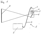
- the single figure shows a schematic block diagram of Panoramic image projector.
- the panoramic image projector 1 comprises a laser source 2, an optical interface 3, an imaging optics 4 and a rotatable by a motor 5 drivable mirror 6.
- the laser source 2 is via at least one optical fiber 7 with the optical Interface 3 connected.
- the glass fiber 7 Depending on the location of the modulation is the glass fiber 7 than simple glass fiber or formed as a picture waveguide.
- a picture waveguide there is a unique association of the optical fibers, i. the position of each Fiber optic cable on the opposite end face is known. The usage a waveguide is always required when the modulation of Radiation power density is made at the laser source.
- the modulation in the optical Interface 3 is made.
- three punctiform lasers transmit the Colors R, G and B via separate optical fibers to the optical interface 3.
- the three point laser light points are widened in strips. This can be done for example by a cylindrical lens or even by a cross-section converter.
- Cross-section transducers are optical waveguides with different cross-sections at the two end faces.
- the three line-shaped colors R, G and B modulated.
- the optical interface 3 reads a Line from the database, not shown. According to the values for R, G and B per pixel, the individual shutters are now controlled in parallel, such that the transmitted radiation power density for each color for each Pixel is set. Behind the light valves then the three colored Strip of light merged into a strip of light. This joined together Light strip is imaged by the imaging optics 4 on the mirror 6 and of pictured there on an example cylindrical screen 8.
Landscapes
- Physics & Mathematics (AREA)
- General Physics & Mathematics (AREA)
- Optics & Photonics (AREA)
- Engineering & Computer Science (AREA)
- Multimedia (AREA)
- Signal Processing (AREA)
- Control Of Indicators Other Than Cathode Ray Tubes (AREA)
Abstract
Description
Die Rechner sind untereinander vernetzt und die Projektoren untereinander kalibriert. Die Bilder werden mit Hilfe von Kalibrationsfiles derart modifiziert, so dass man in der kreisförmigen Abbildung Zylinderkoordinaten erhält. Je nach benötigter geometrischer Auflösung des Systems müssen eine entsprechende Anzahl Projektoren eingesetzt werden, was relativ teuer ist.
Claims (11)
- Panorama-Bildprojektor, umfassend einen Projektor und eine Datenquelle, wobei der Projektor mindestens eine Lichtquelle, eine Einrichtung zur Erzeugung eines zeilenförmigen RGB-Bildes und eine Projektionsoptik umfasst, und die Daten eines Panoramabildes zeilenförmig als R-, G- und B-Bild in der Datenquelle abgespeichert sind,
dadurch gekennzeichnet, das
die Lichtquelle aus mindestens drei Lasern ausgebildet ist, die im R-, G- und B-Bereich des Spektrums emittieren, wobei der Projektor synchronisiert zur Zeilenfrequenz der Datenquelle rotierbar antreibbar ist oder die Projektionsoptik (4) den zeilenförmigen Ausschnitt auf mindestens einen Spiegel (6) abbildet und der Spiegel (6) synchronisiert zur Zeilenfrequenz der Datenquelle rotierbar antreibbar ist. - Panorama-Bildprojektor nach Anspruch 1, dadurch gekennzeichnet, dass die Laser als Laser-Dioden-Zeilen ausgebildet sind.
- Panorama-Bildprojektor nach Anspruch 1, dadurch gekennzeichnet, dass die Laser als punktförmige Laser ausgebildet sind, denen eine Einrichtung zur zeilenförmigen Aufweitung der punktförmigen Strahlung zugeordnet ist.
- Panorama-Bildprojektor nach einem der vorangegangenen Ansprüche,
dadurch gekennzeichnet, dass die Laser in ihrer Lichtleistung modulierbar ausgebildet sind. - Panorama-Bildprojektor nach einem der vorangegangenen Ansprüche,
dadurch gekennzeichnet, dass den Lasern steuerbare Lichtventile zugeordnet sind, mittels derer die Lichtleistung modulierbar ist, wobei die Lichtventile zur Zeilenfrequenz synchronisiert ansteuerbar sind. - Panorama-Bildprojektor nach Anspruch 5, dadurch gekennzeichnet, dass die Lichtventile als piezogesteuerte Shutter-Klappen ausgebildet sind.
- Panorama-Bildprojektor nach Anspruch 6, dadurch gekennzeichnet, dass die piezogesteuerten Shutter-Klappen als Mikrospiegel mit zugeordneten Piezoelementen ausgebildet sind.
- Panorama-Bildprojektor nach einem der Ansprüche 5 bis 7, dadurch gekennzeichnet, dass die Lichtventile an den Lasern angeordnet sind.
- Panorama-Bildprojektor nach einem der Ansprüche 5 bis 8, dadurch gekennzeichnet, dass die Lichtventile mit einer Frequenz größer 100 Hz angesteuert werden.
- Panorama-Bildprojektor nach Anspruch 9, dadurch gekennzeichnet, dass die Lichtventile in zwei Stellungen ansteuerbar sind, wobei in einer ersten Stellung das Laserlicht in eine Faser eingekoppelt und in einer zweiten Stellung in eine Lichtfalle gestrahlt wird.
- Panorama-Bildprojektor nach einem der vorangegangenen Ansprüche,
dadurch gekennzeichnet, dass die Datenbasis der Datenquelle das Panoramabild zeilenweise aus unterschiedlichem Blickwinkel umfasst, die synchronisiert nacheinander oder mit unterschiedlichen Polarisationsgraden gleichzeitig abbildbar sind.
Applications Claiming Priority (2)
| Application Number | Priority Date | Filing Date | Title |
|---|---|---|---|
| DE102004027340 | 2004-05-27 | ||
| DE200410027340 DE102004027340A1 (de) | 2004-05-27 | 2004-05-27 | Panorama-Bildprojektor |
Publications (1)
| Publication Number | Publication Date |
|---|---|
| EP1601210A1 true EP1601210A1 (de) | 2005-11-30 |
Family
ID=34936970
Family Applications (1)
| Application Number | Title | Priority Date | Filing Date |
|---|---|---|---|
| EP05011413A Withdrawn EP1601210A1 (de) | 2004-05-27 | 2005-05-26 | Panorama-Bildprojektor |
Country Status (2)
| Country | Link |
|---|---|
| EP (1) | EP1601210A1 (de) |
| DE (1) | DE102004027340A1 (de) |
Citations (9)
| Publication number | Priority date | Publication date | Assignee | Title |
|---|---|---|---|---|
| US3992718A (en) * | 1975-01-23 | 1976-11-16 | The United States Of America As Represented By The Secretary Of The Navy | Color panoramic laser projector |
| US5033814A (en) * | 1989-04-10 | 1991-07-23 | Nilford Laboratories, Inc. | Line light source |
| US5126836A (en) * | 1989-11-01 | 1992-06-30 | Aura Systems, Inc. | Actuated mirror optical intensity modulation |
| US5920361A (en) * | 1993-02-03 | 1999-07-06 | Nitor | Methods and apparatus for image projection |
| US20020171778A1 (en) * | 2001-05-16 | 2002-11-21 | Hubby Laurence M. | Optical system for full color, video projector using single light valve with plural sub-pixel reflectors |
| US6499846B1 (en) * | 1998-11-05 | 2002-12-31 | Ltd Gmbh & Co. Laser-Display-Technologie Kg | Projection system with projector and deflection mirror |
| US6511182B1 (en) * | 2001-11-13 | 2003-01-28 | Eastman Kodak Company | Autostereoscopic optical apparatus using a scanned linear image source |
| US20030112507A1 (en) * | 2000-10-12 | 2003-06-19 | Adam Divelbiss | Method and apparatus for stereoscopic display using column interleaved data with digital light processing |
| WO2004030354A1 (en) * | 2002-09-30 | 2004-04-08 | Jung Chan Ko | Large-scale image display apparatus using optical fiber |
Family Cites Families (2)
| Publication number | Priority date | Publication date | Assignee | Title |
|---|---|---|---|---|
| DE19641656A1 (de) * | 1996-10-09 | 1998-04-23 | Zeiss Carl Jena Gmbh | Vorrichtung zum Erzeugen ringförmiger Bilder |
| DE19641480A1 (de) * | 1996-10-09 | 1998-04-30 | Tan Helmut | Verfahren zur stereoskopischen Projektion von 3D-Bilddarstellungen auf einer Bildanzeigeeinrichtung |
-
2004
- 2004-05-27 DE DE200410027340 patent/DE102004027340A1/de not_active Withdrawn
-
2005
- 2005-05-26 EP EP05011413A patent/EP1601210A1/de not_active Withdrawn
Patent Citations (9)
| Publication number | Priority date | Publication date | Assignee | Title |
|---|---|---|---|---|
| US3992718A (en) * | 1975-01-23 | 1976-11-16 | The United States Of America As Represented By The Secretary Of The Navy | Color panoramic laser projector |
| US5033814A (en) * | 1989-04-10 | 1991-07-23 | Nilford Laboratories, Inc. | Line light source |
| US5126836A (en) * | 1989-11-01 | 1992-06-30 | Aura Systems, Inc. | Actuated mirror optical intensity modulation |
| US5920361A (en) * | 1993-02-03 | 1999-07-06 | Nitor | Methods and apparatus for image projection |
| US6499846B1 (en) * | 1998-11-05 | 2002-12-31 | Ltd Gmbh & Co. Laser-Display-Technologie Kg | Projection system with projector and deflection mirror |
| US20030112507A1 (en) * | 2000-10-12 | 2003-06-19 | Adam Divelbiss | Method and apparatus for stereoscopic display using column interleaved data with digital light processing |
| US20020171778A1 (en) * | 2001-05-16 | 2002-11-21 | Hubby Laurence M. | Optical system for full color, video projector using single light valve with plural sub-pixel reflectors |
| US6511182B1 (en) * | 2001-11-13 | 2003-01-28 | Eastman Kodak Company | Autostereoscopic optical apparatus using a scanned linear image source |
| WO2004030354A1 (en) * | 2002-09-30 | 2004-04-08 | Jung Chan Ko | Large-scale image display apparatus using optical fiber |
Also Published As
| Publication number | Publication date |
|---|---|
| DE102004027340A1 (de) | 2005-12-22 |
Similar Documents
| Publication | Publication Date | Title |
|---|---|---|
| DE69323846T2 (de) | Autostereoskopisches Wiedergabegerät | |
| DE69307561T2 (de) | Verfahren und Vorrichtung für die Aufnahme stereoskopischer Bilder und dafür verwendetes Linsenrasterkopiermaterial | |
| EP0909517B1 (de) | Verfahren und system zur projektion von bildern auf einen schirm mit hilfe eines lichtbündels | |
| DE69123288T2 (de) | Anzeigegerät | |
| DE60201634T2 (de) | Verfahren und Vorrichtung zur Erzeugung einer sich verschiebenden Beleuchtung | |
| EP0907902B1 (de) | Verfahren zur dreidimensionalen bilddarstellung auf einer grossbildprojektionsfläche mittels eines laser-projektors | |
| WO2012055050A1 (de) | Augenuntersuchungsgerät mit digitaler bildausgabe | |
| DE69328906T2 (de) | Verfahren und gerät zum erzeugen von dreidimensionalen bildern | |
| DE10251696B4 (de) | Optische Kupplungseinrichtung verwendende optische Einrichtung | |
| DE10034995A1 (de) | Verfahren und Vorrichtung zum genauen Positionieren von Linsenrasteranordnungen mit periodischen Strukturen bezüglich zusammengesetzter Bilder | |
| DE19537356C1 (de) | Verfahren und Vorrichtung zur Erzeugung eines stereoskopischen Videobildes | |
| DE102020133627A1 (de) | Verfahren und Intraoralscanner zum Erfassen der Topographie der Oberfläche eines transluzenten, insbesondere dentalen, Objektes | |
| DE10065153A1 (de) | Verfahren und Vorrichtung zum Drucken großformatiger Linsenrasterbilder | |
| DE3112548A1 (de) | "verfahren und vorrichtung zur lippensynchronen raeumlichen wiedergabe von fs-bildern bei normaler uebertragungsbandbreite" | |
| DE69617807T2 (de) | Projektionsbildanzeigegerät | |
| DE69431399T2 (de) | Dichroitisches immersionssystem für videoprojektor mit einem einzelnen projektionsobjektiv | |
| DE4125241C2 (de) | Laserprojektor | |
| WO2002017017A1 (de) | Projektionsanordnung zum projizieren eines bildes auf eine projektionsfläche | |
| DE10034967A1 (de) | Verfahren und Vorrichtung zum genauen Positionieren von Linsenrasteranordnungen mit periodischen Strukturen bezüglich zusammengesetzter Bilder | |
| DE10332275B4 (de) | Panorama-Bildprojektor | |
| DE102004027340A1 (de) | Panorama-Bildprojektor | |
| DE102004063491B4 (de) | Stereoprojektor, Projektionssystem und Verfahren zum Projizieren einer Stereo-Abbildung | |
| DE3044217C2 (de) | ||
| DE4405531C2 (de) | Verfahren und Vorrichtung zur Erfassung der Geometrie räumlicher Objekte | |
| EP3553590B1 (de) | Vorrichtung und verfahren zur aufzeichnung, übertragung und räumlichen rekonstruktion von bildern dreidimensionaler objekte |
Legal Events
| Date | Code | Title | Description |
|---|---|---|---|
| PUAI | Public reference made under article 153(3) epc to a published international application that has entered the european phase |
Free format text: ORIGINAL CODE: 0009012 |
|
| AK | Designated contracting states |
Kind code of ref document: A1 Designated state(s): AT BE BG CH CY CZ DE DK EE ES FI FR GB GR HU IE IS IT LI LT LU MC NL PL PT RO SE SI SK TR |
|
| AX | Request for extension of the european patent |
Extension state: AL BA HR LV MK YU |
|
| 17P | Request for examination filed |
Effective date: 20051031 |
|
| RAP1 | Party data changed (applicant data changed or rights of an application transferred) |
Owner name: DEUTSCHES ZENTRUM FUER LUFT- UND RAUMFAHRT E.V. |
|
| AKX | Designation fees paid |
Designated state(s): DE FR GB |
|
| 17Q | First examination report despatched |
Effective date: 20060118 |
|
| STAA | Information on the status of an ep patent application or granted ep patent |
Free format text: STATUS: THE APPLICATION IS DEEMED TO BE WITHDRAWN |
|
| 18D | Application deemed to be withdrawn |
Effective date: 20090623 |