EP1601085A1 - Hub unit for use in electrically movable wheels and vehicle comprising the hub unit - Google Patents
Hub unit for use in electrically movable wheels and vehicle comprising the hub unit Download PDFInfo
- Publication number
- EP1601085A1 EP1601085A1 EP05011355A EP05011355A EP1601085A1 EP 1601085 A1 EP1601085 A1 EP 1601085A1 EP 05011355 A EP05011355 A EP 05011355A EP 05011355 A EP05011355 A EP 05011355A EP 1601085 A1 EP1601085 A1 EP 1601085A1
- Authority
- EP
- European Patent Office
- Prior art keywords
- hub
- rotor
- hub unit
- support shaft
- stator
- Prior art date
- Legal status (The legal status is an assumption and is not a legal conclusion. Google has not performed a legal analysis and makes no representation as to the accuracy of the status listed.)
- Granted
Links
- 239000002184 metal Substances 0.000 claims description 40
- 230000002093 peripheral effect Effects 0.000 claims description 7
- 238000010276 construction Methods 0.000 abstract description 4
- 238000004804 winding Methods 0.000 description 9
- 239000000463 material Substances 0.000 description 3
- 238000005452 bending Methods 0.000 description 1
- 238000003754 machining Methods 0.000 description 1
- 230000004048 modification Effects 0.000 description 1
- 238000012986 modification Methods 0.000 description 1
- 238000013021 overheating Methods 0.000 description 1
- 230000005855 radiation Effects 0.000 description 1
- 239000013585 weight reducing agent Substances 0.000 description 1
Images





Classifications
-
- H—ELECTRICITY
- H02—GENERATION; CONVERSION OR DISTRIBUTION OF ELECTRIC POWER
- H02K—DYNAMO-ELECTRIC MACHINES
- H02K7/00—Arrangements for handling mechanical energy structurally associated with dynamo-electric machines, e.g. structural association with mechanical driving motors or auxiliary dynamo-electric machines
- H02K7/10—Structural association with clutches, brakes, gears, pulleys or mechanical starters
- H02K7/116—Structural association with clutches, brakes, gears, pulleys or mechanical starters with gears
-
- B—PERFORMING OPERATIONS; TRANSPORTING
- B60—VEHICLES IN GENERAL
- B60B—VEHICLE WHEELS; CASTORS; AXLES FOR WHEELS OR CASTORS; INCREASING WHEEL ADHESION
- B60B27/00—Hubs
- B60B27/0005—Hubs with ball bearings
-
- B—PERFORMING OPERATIONS; TRANSPORTING
- B60—VEHICLES IN GENERAL
- B60B—VEHICLE WHEELS; CASTORS; AXLES FOR WHEELS OR CASTORS; INCREASING WHEEL ADHESION
- B60B27/00—Hubs
- B60B27/0015—Hubs for driven wheels
- B60B27/0021—Hubs for driven wheels characterised by torque transmission means from drive axle
-
- B—PERFORMING OPERATIONS; TRANSPORTING
- B60—VEHICLES IN GENERAL
- B60B—VEHICLE WHEELS; CASTORS; AXLES FOR WHEELS OR CASTORS; INCREASING WHEEL ADHESION
- B60B27/00—Hubs
- B60B27/02—Hubs adapted to be rotatably arranged on axle
-
- B—PERFORMING OPERATIONS; TRANSPORTING
- B60—VEHICLES IN GENERAL
- B60L—PROPULSION OF ELECTRICALLY-PROPELLED VEHICLES; SUPPLYING ELECTRIC POWER FOR AUXILIARY EQUIPMENT OF ELECTRICALLY-PROPELLED VEHICLES; ELECTRODYNAMIC BRAKE SYSTEMS FOR VEHICLES IN GENERAL; MAGNETIC SUSPENSION OR LEVITATION FOR VEHICLES; MONITORING OPERATING VARIABLES OF ELECTRICALLY-PROPELLED VEHICLES; ELECTRIC SAFETY DEVICES FOR ELECTRICALLY-PROPELLED VEHICLES
- B60L3/00—Electric devices on electrically-propelled vehicles for safety purposes; Monitoring operating variables, e.g. speed, deceleration or energy consumption
- B60L3/0023—Detecting, eliminating, remedying or compensating for drive train abnormalities, e.g. failures within the drive train
- B60L3/0061—Detecting, eliminating, remedying or compensating for drive train abnormalities, e.g. failures within the drive train relating to electrical machines
-
- B—PERFORMING OPERATIONS; TRANSPORTING
- B60—VEHICLES IN GENERAL
- B60L—PROPULSION OF ELECTRICALLY-PROPELLED VEHICLES; SUPPLYING ELECTRIC POWER FOR AUXILIARY EQUIPMENT OF ELECTRICALLY-PROPELLED VEHICLES; ELECTRODYNAMIC BRAKE SYSTEMS FOR VEHICLES IN GENERAL; MAGNETIC SUSPENSION OR LEVITATION FOR VEHICLES; MONITORING OPERATING VARIABLES OF ELECTRICALLY-PROPELLED VEHICLES; ELECTRIC SAFETY DEVICES FOR ELECTRICALLY-PROPELLED VEHICLES
- B60L50/00—Electric propulsion with power supplied within the vehicle
- B60L50/20—Electric propulsion with power supplied within the vehicle using propulsion power generated by humans or animals
-
- B—PERFORMING OPERATIONS; TRANSPORTING
- B60—VEHICLES IN GENERAL
- B60L—PROPULSION OF ELECTRICALLY-PROPELLED VEHICLES; SUPPLYING ELECTRIC POWER FOR AUXILIARY EQUIPMENT OF ELECTRICALLY-PROPELLED VEHICLES; ELECTRODYNAMIC BRAKE SYSTEMS FOR VEHICLES IN GENERAL; MAGNETIC SUSPENSION OR LEVITATION FOR VEHICLES; MONITORING OPERATING VARIABLES OF ELECTRICALLY-PROPELLED VEHICLES; ELECTRIC SAFETY DEVICES FOR ELECTRICALLY-PROPELLED VEHICLES
- B60L50/00—Electric propulsion with power supplied within the vehicle
- B60L50/50—Electric propulsion with power supplied within the vehicle using propulsion power supplied by batteries or fuel cells
- B60L50/60—Electric propulsion with power supplied within the vehicle using propulsion power supplied by batteries or fuel cells using power supplied by batteries
- B60L50/66—Arrangements of batteries
-
- B—PERFORMING OPERATIONS; TRANSPORTING
- B62—LAND VEHICLES FOR TRAVELLING OTHERWISE THAN ON RAILS
- B62M—RIDER PROPULSION OF WHEELED VEHICLES OR SLEDGES; POWERED PROPULSION OF SLEDGES OR SINGLE-TRACK CYCLES; TRANSMISSIONS SPECIALLY ADAPTED FOR SUCH VEHICLES
- B62M6/00—Rider propulsion of wheeled vehicles with additional source of power, e.g. combustion engine or electric motor
- B62M6/40—Rider propelled cycles with auxiliary electric motor
- B62M6/60—Rider propelled cycles with auxiliary electric motor power-driven at axle parts
- B62M6/65—Rider propelled cycles with auxiliary electric motor power-driven at axle parts with axle and driving shaft arranged coaxially
-
- H—ELECTRICITY
- H02—GENERATION; CONVERSION OR DISTRIBUTION OF ELECTRIC POWER
- H02K—DYNAMO-ELECTRIC MACHINES
- H02K5/00—Casings; Enclosures; Supports
-
- H—ELECTRICITY
- H02—GENERATION; CONVERSION OR DISTRIBUTION OF ELECTRIC POWER
- H02K—DYNAMO-ELECTRIC MACHINES
- H02K5/00—Casings; Enclosures; Supports
- H02K5/04—Casings or enclosures characterised by the shape, form or construction thereof
- H02K5/15—Mounting arrangements for bearing-shields or end plates
-
- B—PERFORMING OPERATIONS; TRANSPORTING
- B60—VEHICLES IN GENERAL
- B60L—PROPULSION OF ELECTRICALLY-PROPELLED VEHICLES; SUPPLYING ELECTRIC POWER FOR AUXILIARY EQUIPMENT OF ELECTRICALLY-PROPELLED VEHICLES; ELECTRODYNAMIC BRAKE SYSTEMS FOR VEHICLES IN GENERAL; MAGNETIC SUSPENSION OR LEVITATION FOR VEHICLES; MONITORING OPERATING VARIABLES OF ELECTRICALLY-PROPELLED VEHICLES; ELECTRIC SAFETY DEVICES FOR ELECTRICALLY-PROPELLED VEHICLES
- B60L2200/00—Type of vehicles
- B60L2200/12—Bikes
-
- B—PERFORMING OPERATIONS; TRANSPORTING
- B60—VEHICLES IN GENERAL
- B60L—PROPULSION OF ELECTRICALLY-PROPELLED VEHICLES; SUPPLYING ELECTRIC POWER FOR AUXILIARY EQUIPMENT OF ELECTRICALLY-PROPELLED VEHICLES; ELECTRODYNAMIC BRAKE SYSTEMS FOR VEHICLES IN GENERAL; MAGNETIC SUSPENSION OR LEVITATION FOR VEHICLES; MONITORING OPERATING VARIABLES OF ELECTRICALLY-PROPELLED VEHICLES; ELECTRIC SAFETY DEVICES FOR ELECTRICALLY-PROPELLED VEHICLES
- B60L2220/00—Electrical machine types; Structures or applications thereof
- B60L2220/10—Electrical machine types
- B60L2220/14—Synchronous machines
-
- B—PERFORMING OPERATIONS; TRANSPORTING
- B60—VEHICLES IN GENERAL
- B60L—PROPULSION OF ELECTRICALLY-PROPELLED VEHICLES; SUPPLYING ELECTRIC POWER FOR AUXILIARY EQUIPMENT OF ELECTRICALLY-PROPELLED VEHICLES; ELECTRODYNAMIC BRAKE SYSTEMS FOR VEHICLES IN GENERAL; MAGNETIC SUSPENSION OR LEVITATION FOR VEHICLES; MONITORING OPERATING VARIABLES OF ELECTRICALLY-PROPELLED VEHICLES; ELECTRIC SAFETY DEVICES FOR ELECTRICALLY-PROPELLED VEHICLES
- B60L2220/00—Electrical machine types; Structures or applications thereof
- B60L2220/40—Electrical machine applications
- B60L2220/44—Wheel Hub motors, i.e. integrated in the wheel hub
-
- B—PERFORMING OPERATIONS; TRANSPORTING
- B60—VEHICLES IN GENERAL
- B60L—PROPULSION OF ELECTRICALLY-PROPELLED VEHICLES; SUPPLYING ELECTRIC POWER FOR AUXILIARY EQUIPMENT OF ELECTRICALLY-PROPELLED VEHICLES; ELECTRODYNAMIC BRAKE SYSTEMS FOR VEHICLES IN GENERAL; MAGNETIC SUSPENSION OR LEVITATION FOR VEHICLES; MONITORING OPERATING VARIABLES OF ELECTRICALLY-PROPELLED VEHICLES; ELECTRIC SAFETY DEVICES FOR ELECTRICALLY-PROPELLED VEHICLES
- B60L2220/00—Electrical machine types; Structures or applications thereof
- B60L2220/50—Structural details of electrical machines
-
- B—PERFORMING OPERATIONS; TRANSPORTING
- B60—VEHICLES IN GENERAL
- B60L—PROPULSION OF ELECTRICALLY-PROPELLED VEHICLES; SUPPLYING ELECTRIC POWER FOR AUXILIARY EQUIPMENT OF ELECTRICALLY-PROPELLED VEHICLES; ELECTRODYNAMIC BRAKE SYSTEMS FOR VEHICLES IN GENERAL; MAGNETIC SUSPENSION OR LEVITATION FOR VEHICLES; MONITORING OPERATING VARIABLES OF ELECTRICALLY-PROPELLED VEHICLES; ELECTRIC SAFETY DEVICES FOR ELECTRICALLY-PROPELLED VEHICLES
- B60L2240/00—Control parameters of input or output; Target parameters
- B60L2240/10—Vehicle control parameters
- B60L2240/36—Temperature of vehicle components or parts
-
- B—PERFORMING OPERATIONS; TRANSPORTING
- B60—VEHICLES IN GENERAL
- B60L—PROPULSION OF ELECTRICALLY-PROPELLED VEHICLES; SUPPLYING ELECTRIC POWER FOR AUXILIARY EQUIPMENT OF ELECTRICALLY-PROPELLED VEHICLES; ELECTRODYNAMIC BRAKE SYSTEMS FOR VEHICLES IN GENERAL; MAGNETIC SUSPENSION OR LEVITATION FOR VEHICLES; MONITORING OPERATING VARIABLES OF ELECTRICALLY-PROPELLED VEHICLES; ELECTRIC SAFETY DEVICES FOR ELECTRICALLY-PROPELLED VEHICLES
- B60L2250/00—Driver interactions
- B60L2250/26—Driver interactions by pedal actuation
-
- Y—GENERAL TAGGING OF NEW TECHNOLOGICAL DEVELOPMENTS; GENERAL TAGGING OF CROSS-SECTIONAL TECHNOLOGIES SPANNING OVER SEVERAL SECTIONS OF THE IPC; TECHNICAL SUBJECTS COVERED BY FORMER USPC CROSS-REFERENCE ART COLLECTIONS [XRACs] AND DIGESTS
- Y02—TECHNOLOGIES OR APPLICATIONS FOR MITIGATION OR ADAPTATION AGAINST CLIMATE CHANGE
- Y02T—CLIMATE CHANGE MITIGATION TECHNOLOGIES RELATED TO TRANSPORTATION
- Y02T10/00—Road transport of goods or passengers
- Y02T10/60—Other road transportation technologies with climate change mitigation effect
- Y02T10/64—Electric machine technologies in electromobility
-
- Y—GENERAL TAGGING OF NEW TECHNOLOGICAL DEVELOPMENTS; GENERAL TAGGING OF CROSS-SECTIONAL TECHNOLOGIES SPANNING OVER SEVERAL SECTIONS OF THE IPC; TECHNICAL SUBJECTS COVERED BY FORMER USPC CROSS-REFERENCE ART COLLECTIONS [XRACs] AND DIGESTS
- Y02—TECHNOLOGIES OR APPLICATIONS FOR MITIGATION OR ADAPTATION AGAINST CLIMATE CHANGE
- Y02T—CLIMATE CHANGE MITIGATION TECHNOLOGIES RELATED TO TRANSPORTATION
- Y02T10/00—Road transport of goods or passengers
- Y02T10/60—Other road transportation technologies with climate change mitigation effect
- Y02T10/70—Energy storage systems for electromobility, e.g. batteries
Definitions
- the present invention relates to hub units for use in electrically movable wheels, and to electrically assisted bicycles, wheelchairs and like vehicles comprising the hub unit.
- FIG. 8 shows an electrically movable wheel hub unit 2 for an electrically assisted bicycle.
- the electrically movable wheel hub unit (hereinafter referred to as the "hub unit”) has a motor 9 comprising a stator 3 and a rotor 4, a planetary gear reduction mechanism 6 coupled to a rotor shaft 41 extending through an end plate 52 of a motor housing 5, a hub 7 enclosing the motor 9 and the reduction mechanism 6 therein and having inner teeth 66a in mesh with planetary gears 65, and fixing support shafts 57, 57a in alignment with the rotor shaft 41 and projecting outward respectively from an end plate 51 on one side of the motor housing 5 opposite to the reduction mechanism 6 and from a planetary gear support frame 61, the support shafts 57, 57a extending outward from the hub 7.
- a motor 9 comprising a stator 3 and a rotor 4
- a planetary gear reduction mechanism 6 coupled to a rotor shaft 41 extending through an end plate 52 of a motor housing 5
- a hub 7 enclosing the motor 9 and the reduction mechanism 6 therein
- the support shafts 57, 57a are fixed to the front fork or rear fork of the bicycle, and the spokes (not shown) of the wheel are fitted into spoke attaching holes 74a in circumferential walls 74, 74 provided around the hub 7.
- the two fixing support shafts 57, 57a which are separate from the rotor shaft 41, are arranged in alignment with the rotator shaft 41, so that the hub unit is complex in construction and requires much labor and time for assembling. Furthermore, the three shafts 41, 57, 57a are likely to be out of alignment owing to errors involved in machining or assembling the components, permitting their axes to deflect relative to one another.
- the present invention provides a hub unit wherein only one fixing support shaft 57 is provided, the support shaft 57 having at least one end projecting outward from a hub 7, and a rotor 4 has a tubular rotating shaft 44 rotatably fitted around the support shaft 57, the hub unit thus being made free of the foregoing problems.
- the invention also provides a vehicle comprising the hub unit.
- the present invention provides an electrically movable wheel hub unit comprising a motor 9 composed of a stator 3 and a rotor 4, a planetary gear reduction mechanism 6 coupled to the rotor 4, a hub 7 enclosing the reduction mechanism 6 therein and having inner teeth 66a formed on an inner surface thereof and meshing with planetary gears 65, the hub 7 being rotatingly drivable by the rotation of the rotor 4, and a fixing support shaft 57 projecting outward from the hub 7 and rotatable relative to the hub 7 on an axis of rotation of the hub 7, the fixing support shaft 57 being provided singly and having at least one end projecting outward from the hub 7, the rotor 4 having a tubular rotating shaft 44 rotatably fitted around the fixing support shaft 57, the tubular rotating shaft 44 being provided with a sun gear 60 of the planetary gear reduction mechanism 6.
- the axis of the rotor 4 will not deflect relative to the fixing support shaft 57 because the rotor shaft 44 is rotatably fitted around the single fixing support shaft 57 having at least one end projecting outward from the hub 7 as described above.
- the hub unit is more simplified in construction and easier to assemble than the conventional hub unit wherein the two fixing support shafts 57, 57a are separate from the rotor shaft 41.
- FIG. 1 shows an example of electrically assisted bicycle 1 having a hub unit 2 of the present invention.
- a hub unit 2 is attached to the lower end of a front fork 12 of the bicycle 1, and the hub unit 2 and the rim 13 of a front wheel 11 are interconnected by spokes 14, 14.
- a battery 17 is mounted on the bicycle between a seat post 15 and a rear wheel 16.
- a sensor (not shown) is provided on a suitable portion on which the pedaling force of the pedals 18 acts for energizing a motor 9 of the hub unit 2 by the battery 17 when the load on the pedals is not smaller than a predetermined value.
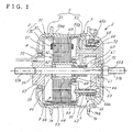
- the hub unit 2 has the above-mentioned motor 9 which comprises a stator 3 and a rotor 4, a hub 7 enclosing the motor 9 therein and rotatingly driven by the rotation of the rotor 4, and a fixing support shaft 57 secured to a motor housing 5, projecting therefrom in alignment with the axis of rotation of the hub 7 and having opposite ends extending outward from the hub 7.
- motor 9 which comprises a stator 3 and a rotor 4, a hub 7 enclosing the motor 9 therein and rotatingly driven by the rotation of the rotor 4, and a fixing support shaft 57 secured to a motor housing 5, projecting therefrom in alignment with the axis of rotation of the hub 7 and having opposite ends extending outward from the hub 7.
- the stator 3 comprises a stack 31 of a specified number of metal plates 31a blanked out and windings 32 provided around the metal plate stack 31.
- Each of the metal plates 31a is in the form of a ring having a plurality of T-shaped projections 31b arranged on the inner periphery of the ring at equal intervals circumferentially thereof and projecting toward the center of the ring.
- the metal plate 31a has twelve projections 31b according to the present embodiment.
- the winding 32 is provided on a stack of projections 31b in phase as a unit.
- Such a metal plate stack 31 is made conventionally by blanking out metal plates 31a from a metal sheet material with a blanking die and stacking the plates as blanked out at the same time.
- burrs created on respective adjacent pairs of blanked-out metal plates 31a, 31a are located at the same position or in alignment. If burrs are formed on each single blanked-out metal plate 31a uniformly circumferentially thereof, the metal plate stack 31 will have a uniform thickness circumferentially thereof.
- the single metal plate stack 31 will have a difference of about 0.1 to 0.3 mm in thickness and has a portion of large thickness and a portion of small thickness.
- the stack 31 is divided into units 31c each comprising a number of blanked-out metal plates 31a, and the units 31c are stacked as displaced from one another through a predetermined angle.
- the units 31c are stacked as displaced from one another through an angle obtained by dividing 360 deg by the number of units 31c to make the metal plate stack 31.
- the number of units 31c is three
- the three units 31c are displaced from one another by 120 deg, and a wire is wound around each of the projection stacks 31b to form the winding 32.
- the metal plate stack 31 can be made easily by blanking out metal plates 31a from a metal sheet material, stacking a specified number of blanked-out metal plates 31a upon blanking, rotating the metal sheet material through a predetermined angle, e.g., through 120 deg according to the present embodiment, within a horizontal plane every time the specified number of metal plates are blanked out.
- the number of inward projections 31b on the metal plate 31b blanked out is limited to a number which can be divided by the number of units 31c.
- the rotor 4 is rotatably disposed inside the stator 3 concentrically therewith.
- the rotor 4 is made by inserting a tubular rotating shaft 44 through the center of a stack 42 of circular metal plates so as to render the shaft 44 rotatable with the metal plate stack 42.
- a plurality of permanent magnets 43 are embedded in the outer peripheral portion of the metal plate stack 42 in parallel to the rotating shaft 44 at equal intervals with S poles and N poles arranged alternately circumferentially of the stack.
- the housing 5 for the motor 9 is made by holding the metal plate stack 31 of the stator 3 between a pair of first and second end plates 51, 52 opposed to each other axially of the stator 3 and fastening the two end plates 51, 52 together with a plurality of bolts 53 inserted through the outer peripheral portion of the stack 31 and tightened up.
- the metal plate stack 31 of the stator 3 serves the function of fixedly positioning the first end plate 51 and the second end plate 52 as spaced apart by a given distance.
- the metal plate stack 31 serves also the function of a cylindrical wall 8 of the motor housing 5 in the conventional hub unit shown in FIG. 8.
- the first end plate 51 and the second end plate 52 are provided at their outer peripheral edges with short inward cylinder portions 54, 55, respectively.
- the short cylinder portions 54, 55 have at their inner ends respective stepped portions 54a, 55a having fitted therein opposite-end outer peripheral edges of the metal plate stack 31.
- the rotating shaft 44 of the rotor 4 is tubular.
- the tubular rotating shaft 44 extends through the second end plate 52 to project outward beyond the second end plate 52.
- a bearing 49 is provided between the shaft 44 and the second end plate 52.
- the first end plate 51 has a boss 56 projecting outward from its center.
- the fixing support shaft 57 extends through and is secured to the first end plate 51 in alignment with the axis of the stator 3.
- the support shaft 57 extends through the boss 56 of the first end plate 51, the tubular rotating shaft 44 of the rotor 4, the planetary gear reduction mechanism 6 to be described later and a closure plate 72 of the hub 7, and has opposite ends projecting outward from the hub 7.
- the opposite ends of the support shat 57 are externally threaded as at 57b for use in mounting the hub unit on the front fork 12 of the bicycle 1.
- Bearings 46, 46 are provided between the tubular rotating shaft 44 of the rotor 4 and the fixing support shaft 57.
- the reduction mechanism is provided externally of the second end plate 52 for transmitting the rotation of the tubular rotating shaft 44 of the rotor 4 upon a speed reduction.
- the reduction mechanism of the present embodiment is a planetary gear reduction mechanism 6.
- the reduction mechanism 6 has a planetary gear support frame 61 provided with three tubular legs 62 projecting toward and bearing against the second end plate 52 and equidistantly spaced circumferentially of the frame.
- the frame 61 is fastened to the second end plate 52 with bolts 63 extending through the respective legs 62.
- the planetary gear 65 comprises a large gear 65a positioned closer to the second end plate 52 and a small gear 65b positioned on the opposite side and coaxial with the gear 65a.
- the large gear 65a of the planetary gear 65 is in mesh with a sun gear 60 formed on an end portion of the tubular rotating shaft 44 of the rotor 4.
- the small gear 65b of the planetary gear 65 is in mesh with inner teeth 66a on the closure plate 72 of the hub 7 to be described later.
- the hub 7 comprises a hub main body 71 generally in the form of a cup which is open at the center of its bottom wall and open over the entire area of the other side, and the above-mentioned closure plate 72 covering the entire opening.
- the hub main body 71 covers the motor housing 5 and the planetary gear reduction mechanism 6.
- a bearing 73 is provided in the bottom opening 70 around the boss 56 on the first end plate 51 of the motor housing 5.
- the closure plate 72 covers the entire opening of the hub main body 71 so as to conceal the support frame 61 of the reduction mechanism 6 and is fastened to the hub main body 71 with bolts 76.
- annular member 66 Fastened with screws to the inner side of the closure plate 72 is an annular member 66 concentric with the fixing support shaft 57.
- the inner teeth 66a meshable with the planetary gears 65 are formed on the inner periphery of the annular member 66.
- a bearing 75 is provided in the closure plate 72 around the fixing support shaft 57.
- the hub main body 71 has a circumferential wall 74 formed on its outer peripheral surface and extending therearound at each of opposite side portions. Spoke attaching holes 74a are formed in the circumferential wall 74 and arranged at regular intervals circumferentially of the wall.
- the battery 17 When a load in excess of a specified value acts on the bicycle pedals 18 upon the pedals being stepped on, the battery 17 energizes the windings 32 of the stator 3, rotating the rotor 4.
- the rotation of the rotor 4 rotates the sun gear 60 on the end of the tubular rotating shaft 44 to rotate the planetary gears 65 in position.
- the rotation of the planetary gears 65 is transmitted through the inner teeth 66a to the hub 7 on a speed reduction, drivingly rotating the front wheel 11.
- the bicycle 1 can be run with a reduced stepping force on the pedals 11.
- tubular rotating shaft 44 of the rotor 4 is rotatably fitted around the fixing support shaft 57 having opposite ends projecting from the hub 7, the axis of the rotor 4 will not deflect relative to the support shaft 57.
- the hub unit is more simplified in construction and easier to assemble than the convention hub unit wherein the rotating shaft of the rotor is provided with two fixing support shafts arranged respectively on opposite sides thereof and separate from the rotating shaft.
- the energization of the windings 32 causes the windings 32 to generate heat, which is given to the stator 3.
- the motor housing 5 does not have a tubular wall which prevents radiation of heat, so that the heat given to the stator 3 is released directly through opening between the pair of end plates 51, 52 holding the stator 3 therebetween, whereby the windings 32 can be prevented from overheating.
- the hub unit can be manufactured at a lower cost and with a weight reduction corresponding to the wall 8.
- stator 3 can be increased in outside diameter by a value corresponding to the cylindrical wall omitted and therefore provides increased torque.
- the parallelism between the end plates 51, 52 involves errors, which produce a bending force acting on the rotating shaft 44 of the rotor 4 supported by bearings on the opposed end plates 51, 52, giving rise to the problem of causing trouble to the smooth rotation of the rotor 4.
- an inherent problem will arise when the metal plate stack 31 of the stator 3 is held between the pair of end plates 51, 52 and if the end plates 51, 52 are fastened together by tightening up the bolts 53 so as to cause the thrust of screws to act on the stack 31 in the direction of stacking as practiced in the present embodiment.
- a plurality of units 31c each comprising a specified number of metal plates 31a blanked out are stacked as displaced from one another by a predetermined angle so as to render the metal plate stack 31 uniform in thickness circumferentially thereof to the greatest possible extent. Even if the end plates 51, 52 are fastened by tightening up the bolts 53 so as to causes the thrust of screws to act on the metal plate stack 31 in the stacking direction, the first and second end plates 51, 52 can therefore be given parallelism with high accuracy.
- the rotor 4 can be rotated smoothly by giving improved parallelism to the bearings for supporting the opposite ends of the rotating shaft 44 of the rotor 4.
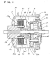
- FIG. 6 shows an embodiment of hub unit 2 comprising a motor 9 having a rotor 4 of the outer type.
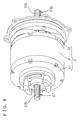
- FIG. 7 is a perspective view of the hub unit 2 with a hub main body 71 removed.
- a fixing support shaft 57 is disposed on the axis of a hub 7 rotatably relative to the hub 7.
- the support shaft 57 has one end extending through and secured to a tubular block 34, and the other end extending through a bearing 75 provided in the center of a closure plate 72 of the hub main body 71 and projecting outward from the hub 7.
- the motor 9 has a stator 3 fastened to the inner end of the block 34 with bolts 53d.
- the rotor 4 of the motor 9 comprises a cylinder 47 provided around the stator 3, a tubular rotating shaft 44 rotatably fitting around the support shaft 57 and having fixed thereto an end plate 48 at one end of the cylinder 47, and permanent magnets 43 provided on the inner surface of the cylinder 47 with N poles and S poles arranged alternately circumferentially of the cylinder 47.
- a sun gear 60 mounted on one end of the tubular rotating shaft 44 operates a planetary gear reduction mechanism 6, and the rotation of planetary gears 65 is transmitted to inner teeth 66a of the hub 7 upon a speed reduction to rotate the hub 7 at a reduced speed in the same manner as in the hub unit 2 shown in FIG. 2.
- the motor housing 5 can be dispensed with, while the rotor 4 can be of reduced weight to further reduce the weight of the hub unit 2.
- the hub unit 2 of the present invention which is useful for electrically assisted bicycles, can be embodied alternatively for hubs for vehicles having wheels, for example, for wheelchairs.
- the fixing support shaft 57 extends outward from opposite ends of the hub 7 so as to support the hub unit 2 at its opposite ends, whereas when the hub unit 2 is to be supported at only one end thereof as in wheelchairs, one end of the fixing support shaft 57 needs only to be projected outward from the hub 7.
Landscapes
- Engineering & Computer Science (AREA)
- Mechanical Engineering (AREA)
- Power Engineering (AREA)
- Transportation (AREA)
- Chemical & Material Sciences (AREA)
- Combustion & Propulsion (AREA)
- Life Sciences & Earth Sciences (AREA)
- Sustainable Development (AREA)
- Sustainable Energy (AREA)
- Connection Of Motors, Electrical Generators, Mechanical Devices, And The Like (AREA)
- Arrangement Or Mounting Of Propulsion Units For Vehicles (AREA)
Abstract
Description
Claims (5)
- An electrically movable wheel hub unit comprising a motor (9) composed of a stator (3) and a rotor (4), a planetary gear reduction mechanism (6) coupled to the rotor (4), a hub (7) enclosing the motor (9) and the reduction mechanism (6) therein and having inner teeth (66a) formed on an inner surface thereof and meshing with planetary gears (65), the hub (7) being rotatingly drivable by the rotation of the rotor (4), and a fixing support shaft (57) rotatable relative to the hub (7) on an axis of rotation of the hub (7),
the fixing support shaft (57) being provided singly and having at least one end projecting outward from the hub (7), the rotor (4) having a tubular rotating shaft (44) rotatably fitted around the fixing support shaft (57), the tubular rotating shaft (44) being provided with a sun gear (60) of the planetary gear reduction mechanism (6). - The electrically movable wheel hub unit according to claim 1 wherein the rotor (4) is of the outer type comprising permanent magnets (43) arranged around an outer peripheral surface of the stator (3).
- The electrically movable wheel hub unit according to claim 1 wherein a pair of end plates (51), (52) are opposed to each other with a stack of metal plates (31) of the stator (3) held therebetween and with the fixing support shaft (57) extending therethrough, the pair of end plates (51), (52) being fastened together with bolts to clamp the metal plate stack (31) therebetween, one of the end plates (51) being fixedly mounted on the support shaft (57), the stator (3) having an outer peripheral surface left exposed to face an inner surface of the hub (7) between the end plates (51), (52).
- The electrically movable wheel hub unit according to claim 3 wherein the metal plate stack (31) comprises units each having a specified number of metal plates (31a) blanked out, and the units are stacked as displaced from one another in the direction of rotation by a predetermined angle.
- A vehicle comprising a wheel having incorporated therein an electrically movable wheel hub unit (2) according to any one of claims 1 to 4.
Applications Claiming Priority (2)
| Application Number | Priority Date | Filing Date | Title |
|---|---|---|---|
| JP2004156969A JP2005335536A (en) | 2004-05-27 | 2004-05-27 | Hub unit for electromotive vehicle wheel, and vehicle with the hub unit |
| JP2004156969 | 2004-05-27 |
Publications (2)
| Publication Number | Publication Date |
|---|---|
| EP1601085A1 true EP1601085A1 (en) | 2005-11-30 |
| EP1601085B1 EP1601085B1 (en) | 2009-04-15 |
Family
ID=34936931
Family Applications (1)
| Application Number | Title | Priority Date | Filing Date |
|---|---|---|---|
| EP05011355A Expired - Lifetime EP1601085B1 (en) | 2004-05-27 | 2005-05-25 | Hub unit for use in electrically movable wheels and vehicle comprising the hub unit |
Country Status (7)
| Country | Link |
|---|---|
| US (1) | US20050264112A1 (en) |
| EP (1) | EP1601085B1 (en) |
| JP (1) | JP2005335536A (en) |
| CN (1) | CN100410136C (en) |
| CA (1) | CA2508440C (en) |
| DE (1) | DE602005013849D1 (en) |
| TW (1) | TWI239929B (en) |
Cited By (9)
| Publication number | Priority date | Publication date | Assignee | Title |
|---|---|---|---|---|
| EP2479099A1 (en) * | 2011-01-24 | 2012-07-25 | Lin Hsiang Huang | Power output device for vehicle |
| EP2562072A1 (en) | 2011-08-25 | 2013-02-27 | Maxon Motor AG | Electric wheel hub drive for a vehicle, in particular for a bicycle |
| CN104104161A (en) * | 2013-04-12 | 2014-10-15 | Lg电子株式会社 | Electric motor |
| WO2015073685A1 (en) * | 2013-11-14 | 2015-05-21 | Razor Usa Llc | Hub motor arrangement or vehicle with hub motor arrangement |
| TWI488411B (en) * | 2011-03-09 | 2015-06-11 | Yamaha Motor Electronics Co | Fixed structure and driving device of stator |
| WO2016183095A1 (en) | 2015-05-12 | 2016-11-17 | Razor Usa Llc | Hub motor arrangement or vehicle with hub motor arrangement |
| US9638285B2 (en) | 2013-11-14 | 2017-05-02 | Razor Usa Llc | Hub motor arrangement or vehicle with hub motor arrangement |
| US12240559B2 (en) | 2021-06-18 | 2025-03-04 | Razor Usa Llc | Hub motor arrangements, systems, and methods |
| US12428102B2 (en) | 2021-05-19 | 2025-09-30 | Razor Usa Llc | Motorized mid-drive unit |
Families Citing this family (47)
| Publication number | Priority date | Publication date | Assignee | Title |
|---|---|---|---|---|
| JP2005335535A (en) * | 2004-05-27 | 2005-12-08 | Sanyo Electric Co Ltd | Hub unit for electromotive vehicle, and vehicle with the hub unit |
| JP4297859B2 (en) * | 2004-09-28 | 2009-07-15 | 三洋電機株式会社 | HUB UNIT FOR ELECTRIC WHEEL AND VEHICLE HAVING THE HUB UNIT |
| JP4217230B2 (en) * | 2005-06-20 | 2009-01-28 | 株式会社シマノ | Power generation equipment for human-powered vehicles |
| US20100236849A1 (en) * | 2008-05-02 | 2010-09-23 | Wishart Randell J | Brushless counter-rotating electric apparatus and system |
| DE202008017587U1 (en) | 2008-10-31 | 2010-02-25 | Ms-Schramberg Holding Gmbh & Co. Kg | rotor |
| US20100212978A1 (en) * | 2009-02-23 | 2010-08-26 | Wen-Hung Huang | Bicycle with two operation molds |
| US20110198144A1 (en) * | 2010-02-12 | 2011-08-18 | Industrial Technology Research Institute | Electric bicycle and motor thereof |
| JP5149938B2 (en) * | 2010-06-11 | 2013-02-20 | 株式会社シマノ | Bicycle hub with built-in motor |
| KR101163108B1 (en) * | 2010-07-23 | 2012-07-06 | 박계정 | An Electromotor for an Electric Automobile |
| US8419581B2 (en) * | 2010-10-01 | 2013-04-16 | Chiu-Hsiang Lo | Hub motor for electric vehicles |
| US8348798B2 (en) * | 2010-10-01 | 2013-01-08 | Chiu-Hsiang Lo | Hub motor for electric vehicles |
| US8419580B2 (en) * | 2010-10-01 | 2013-04-16 | Chiu-Hsiang Lo | Electric wheel for electric vehicles |
| JP2012086804A (en) * | 2010-10-22 | 2012-05-10 | Tokyo R & D Co Ltd | Electrically-assisted bicycle |
| JP4959837B1 (en) * | 2010-12-06 | 2012-06-27 | パナソニック株式会社 | Electric hub device and electric bicycle |
| JP5634842B2 (en) * | 2010-12-06 | 2014-12-03 | Ntn株式会社 | Planetary gear mechanism and hub motor device for battery-assisted bicycle equipped with the same |
| JP5300830B2 (en) * | 2010-12-24 | 2013-09-25 | 株式会社シマノ | Bicycle hub with built-in motor |
| JP5292387B2 (en) * | 2010-12-24 | 2013-09-18 | 株式会社シマノ | Bicycle hub with built-in motor |
| JP5185360B2 (en) | 2010-12-24 | 2013-04-17 | 株式会社シマノ | Bicycle hub with built-in motor |
| JP2012214150A (en) * | 2011-03-31 | 2012-11-08 | Honda Motor Co Ltd | Electric vehicle |
| CN102170214B (en) * | 2011-04-11 | 2012-12-19 | 温岭市九洲电机制造有限公司 | Rear wheel of direct-current brushless permanent-magnet motor |
| JP2012228966A (en) * | 2011-04-26 | 2012-11-22 | Alphana Technology Co Ltd | In-wheel motor |
| KR101762447B1 (en) | 2011-08-09 | 2017-07-27 | 엘지이노텍 주식회사 | Traction motor module |
| CN104136314B (en) * | 2012-02-22 | 2016-12-21 | 松下电器产业株式会社 | Electronic hub unit and electric bicycle |
| JP6006137B2 (en) * | 2013-02-18 | 2016-10-12 | アスモ株式会社 | Drive device |
| US20150203167A1 (en) * | 2014-01-17 | 2015-07-23 | Neal T. Saiki | Front Axle Retention for an Electric Cycle |
| TWI680908B (en) * | 2014-12-17 | 2020-01-01 | 英商威廉斯精進工程有限公司 | An electric drive wheel hub system for a vehicle and a vehicle incorporating the same |
| KR20160074765A (en) * | 2014-12-18 | 2016-06-29 | 주식회사 만도 | Hub motor structure |
| JP2017036825A (en) * | 2015-08-07 | 2017-02-16 | 日本電産サンキョー株式会社 | Planetary gear reducer and drive mechanism |
| US10537764B2 (en) | 2015-08-07 | 2020-01-21 | Icon Health & Fitness, Inc. | Emergency stop with magnetic brake for an exercise device |
| CN105216612A (en) * | 2015-09-28 | 2016-01-06 | 陕西法士特齿轮有限责任公司 | A kind of commercial electric wheel limit motor driven systems |
| US10625137B2 (en) | 2016-03-18 | 2020-04-21 | Icon Health & Fitness, Inc. | Coordinated displays in an exercise device |
| US10493349B2 (en) | 2016-03-18 | 2019-12-03 | Icon Health & Fitness, Inc. | Display on exercise device |
| CN105966541B (en) * | 2016-07-01 | 2021-08-17 | 武汉天腾动力科技有限公司 | Mid Motor for Bicycle |
| US10625114B2 (en) | 2016-11-01 | 2020-04-21 | Icon Health & Fitness, Inc. | Elliptical and stationary bicycle apparatus including row functionality |
| TWI637770B (en) | 2016-11-01 | 2018-10-11 | 美商愛康運動與健康公司 | Drop-in pivot configuration for stationary bikes |
| WO2018132741A1 (en) | 2017-01-14 | 2018-07-19 | Icon Health & Fitness, Inc. | Exercise cycle |
| JP7155569B2 (en) * | 2017-09-15 | 2022-10-19 | 日本電産株式会社 | drive |
| CN109510364B (en) * | 2017-09-15 | 2021-04-16 | 日本电产株式会社 | drive |
| CN109510390B (en) * | 2017-09-15 | 2021-07-09 | 日本电产株式会社 | drive |
| JP7192225B2 (en) * | 2018-03-16 | 2022-12-20 | 日本電産株式会社 | drive |
| AU2019201928B2 (en) * | 2018-03-23 | 2020-10-22 | Wheeltug plc | Epicyclic gearbox |
| CN109586498B (en) * | 2018-12-20 | 2024-07-02 | 珠海格力电器股份有限公司 | Motorized spindle and motor |
| KR102434902B1 (en) * | 2020-10-26 | 2022-08-22 | 주식회사 현대케피코 | In-wheel motor apparatus |
| CN112591005A (en) * | 2020-12-31 | 2021-04-02 | 冠亿精密工业(昆山)有限公司 | Microminiature electric hub |
| DE102022133475B3 (en) | 2022-12-15 | 2024-05-29 | Porsche Ebike Performance Gmbh | Bicycle hub, system, bicycle and method for assembling a bicycle hub |
| DE102024212016A1 (en) * | 2024-12-17 | 2026-06-18 | Robert Bosch Gesellschaft mit beschränkter Haftung | Hub unit for an electrically powered two-wheeler with sealed cable routing |
| CN120915035A (en) * | 2025-08-08 | 2025-11-07 | 江苏牧伦智能科技有限公司 | Hub motor for electric bicycle |
Citations (4)
| Publication number | Priority date | Publication date | Assignee | Title |
|---|---|---|---|---|
| FR1517088A (en) * | 1967-02-03 | 1968-03-15 | Drouard Moteurs | Improvements to electrical machines |
| DE19805679A1 (en) * | 1998-02-12 | 1999-08-19 | Zahnradfabrik Friedrichshafen | Compact wheel hub drive |
| DE20018466U1 (en) * | 2000-10-27 | 2001-04-05 | diro Konstruktion GmbH & Co. KG, 38471 Rühen | Manual transmission for a bicycle with an electric motor |
| JP2003164110A (en) * | 2001-11-28 | 2003-06-06 | Sanyo Electric Co Ltd | Drive motor for electric assist bicycle |
Family Cites Families (9)
| Publication number | Priority date | Publication date | Assignee | Title |
|---|---|---|---|---|
| US3812928A (en) * | 1972-05-12 | 1974-05-28 | Allis Chalmers | Electric powered wheel |
| DE2629532A1 (en) * | 1975-07-03 | 1977-01-27 | Sev Alternateurs | METHOD AND DEVICE FOR A STATOR OR ROTOR OF AN ELECTRIC ROTATING MACHINE |
| CN85203823U (en) * | 1985-09-10 | 1986-07-09 | 重庆电机厂 | Tyre-driving electric motor for light electrically-driven vehicle especially for bicycle |
| US4854034A (en) * | 1988-05-27 | 1989-08-08 | General Electric Company | Method for producing a stack of laminations with skewed conductor slots |
| US5570503A (en) * | 1995-04-28 | 1996-11-05 | General Electric Company | Method for making an electric motor stator |
| DE19732637C5 (en) * | 1997-07-29 | 2006-09-14 | Daimlerchrysler Ag | Electric drive for a wheel hub |
| CN2322312Y (en) * | 1998-04-20 | 1999-06-02 | 吴一生 | Bicycle electric wheel hub |
| CN2534041Y (en) * | 2002-04-03 | 2003-02-05 | 田立兴 | DC brushless electric wheel hub |
| CN2727041Y (en) * | 2004-05-17 | 2005-09-21 | 湖北亿州微特电机有限公司 | Brushless electric wheel hub without iron core |
-
2004
- 2004-05-27 JP JP2004156969A patent/JP2005335536A/en active Pending
- 2004-10-05 TW TW093130097A patent/TWI239929B/en not_active IP Right Cessation
-
2005
- 2005-01-19 CN CNB2005100038870A patent/CN100410136C/en not_active Expired - Fee Related
- 2005-05-25 EP EP05011355A patent/EP1601085B1/en not_active Expired - Lifetime
- 2005-05-25 DE DE602005013849T patent/DE602005013849D1/en not_active Expired - Lifetime
- 2005-05-25 US US11/137,839 patent/US20050264112A1/en not_active Abandoned
- 2005-05-26 CA CA002508440A patent/CA2508440C/en not_active Expired - Fee Related
Patent Citations (4)
| Publication number | Priority date | Publication date | Assignee | Title |
|---|---|---|---|---|
| FR1517088A (en) * | 1967-02-03 | 1968-03-15 | Drouard Moteurs | Improvements to electrical machines |
| DE19805679A1 (en) * | 1998-02-12 | 1999-08-19 | Zahnradfabrik Friedrichshafen | Compact wheel hub drive |
| DE20018466U1 (en) * | 2000-10-27 | 2001-04-05 | diro Konstruktion GmbH & Co. KG, 38471 Rühen | Manual transmission for a bicycle with an electric motor |
| JP2003164110A (en) * | 2001-11-28 | 2003-06-06 | Sanyo Electric Co Ltd | Drive motor for electric assist bicycle |
Non-Patent Citations (1)
| Title |
|---|
| PATENT ABSTRACTS OF JAPAN vol. 2003, no. 10 8 October 2003 (2003-10-08) * |
Cited By (20)
| Publication number | Priority date | Publication date | Assignee | Title |
|---|---|---|---|---|
| EP2479099A1 (en) * | 2011-01-24 | 2012-07-25 | Lin Hsiang Huang | Power output device for vehicle |
| TWI488411B (en) * | 2011-03-09 | 2015-06-11 | Yamaha Motor Electronics Co | Fixed structure and driving device of stator |
| EP2562072A1 (en) | 2011-08-25 | 2013-02-27 | Maxon Motor AG | Electric wheel hub drive for a vehicle, in particular for a bicycle |
| US9308965B2 (en) | 2011-08-25 | 2016-04-12 | Maxon Motor Ag | Electric wheel hub drive for a vehicle, in particular a bicycle, including a stator with an ironless hollow cylindrical stator winding |
| CN104104161B (en) * | 2013-04-12 | 2017-04-12 | Lg电子株式会社 | Electric motor |
| CN104104161A (en) * | 2013-04-12 | 2014-10-15 | Lg电子株式会社 | Electric motor |
| EP2790300A3 (en) * | 2013-04-12 | 2015-07-29 | LG Electronics Inc. | Electric Motor |
| US9660500B2 (en) | 2013-11-14 | 2017-05-23 | Razor Usa Llc | Hub motor arrangement or vehicle with hub motor arrangement |
| US9638285B2 (en) | 2013-11-14 | 2017-05-02 | Razor Usa Llc | Hub motor arrangement or vehicle with hub motor arrangement |
| WO2015073685A1 (en) * | 2013-11-14 | 2015-05-21 | Razor Usa Llc | Hub motor arrangement or vehicle with hub motor arrangement |
| US10226997B2 (en) | 2013-11-14 | 2019-03-12 | Razor Usa Llc | Hub motor arrangement or vehicle with hub motor arrangement |
| US10432064B2 (en) | 2013-11-14 | 2019-10-01 | Razor Usa Llc | Hub motor arrangement or vehicle with hub motor arrangement |
| US10897181B2 (en) | 2013-11-14 | 2021-01-19 | Razor Usa Llc | Hub motor arrangement or vehicle with hub motor arrangement |
| US10899224B2 (en) | 2013-11-14 | 2021-01-26 | Razor Usa Llc | Hub motor arrangement or vehicle with hub motor arrangement |
| US11472284B2 (en) | 2013-11-14 | 2022-10-18 | Razor Usa Llc | Hub motor arrangement or vehicle with hub motor arrangement |
| US11901796B2 (en) | 2013-11-14 | 2024-02-13 | Razor Usa Llc | Hub motor arrangement or vehicle with hub motor arrangement |
| WO2016183095A1 (en) | 2015-05-12 | 2016-11-17 | Razor Usa Llc | Hub motor arrangement or vehicle with hub motor arrangement |
| EP3294617A4 (en) * | 2015-05-12 | 2019-03-13 | Razor USA LLC | DEVICE FORMING A HUB OR VEHICLE ENGINE WITH A HUB ENGINE DEVICE |
| US12428102B2 (en) | 2021-05-19 | 2025-09-30 | Razor Usa Llc | Motorized mid-drive unit |
| US12240559B2 (en) | 2021-06-18 | 2025-03-04 | Razor Usa Llc | Hub motor arrangements, systems, and methods |
Also Published As
| Publication number | Publication date |
|---|---|
| TWI239929B (en) | 2005-09-21 |
| CN1702015A (en) | 2005-11-30 |
| EP1601085B1 (en) | 2009-04-15 |
| JP2005335536A (en) | 2005-12-08 |
| US20050264112A1 (en) | 2005-12-01 |
| CA2508440A1 (en) | 2005-11-27 |
| CA2508440C (en) | 2007-08-14 |
| CN100410136C (en) | 2008-08-13 |
| DE602005013849D1 (en) | 2009-05-28 |
| TW200538352A (en) | 2005-12-01 |
Similar Documents
| Publication | Publication Date | Title |
|---|---|---|
| CA2508440C (en) | Hub unit for use in electrically movable wheels and vehicle comprising the hub unit | |
| CA2508439C (en) | Hub unit for use in electrically movable wheels and vehicle comprising the hub unit | |
| US7472770B2 (en) | Hub unit for use in electrically movable wheels and vehicle comprising the hub unit | |
| US8674573B2 (en) | Direct-current motor and hub unit | |
| EP1630026B1 (en) | Housing structure of in-wheel motor | |
| US10625819B2 (en) | Construction of motorized wheel for vehicle motorization | |
| JP2021041860A (en) | Drive unit | |
| JP2014177265A (en) | Drive device | |
| WO2012137427A1 (en) | Hub unit and electric bicycle | |
| KR101870441B1 (en) | Planetary Gear Train for Transmission of e-bike motor | |
| JP2002331987A (en) | Hub with power unit for electric assist bicycle | |
| JP2009090982A (en) | Hub unit for motor-driven wheel and vehicle provided with the same hub unit | |
| JP2004067039A (en) | Hub motor unit | |
| CN117203120B (en) | Wheel hubs and electric vehicles | |
| TW202329586A (en) | Power generator for human powered vehicle |
Legal Events
| Date | Code | Title | Description |
|---|---|---|---|
| PUAI | Public reference made under article 153(3) epc to a published international application that has entered the european phase |
Free format text: ORIGINAL CODE: 0009012 |
|
| AK | Designated contracting states |
Kind code of ref document: A1 Designated state(s): AT BE BG CH CY CZ DE DK EE ES FI FR GB GR HU IE IS IT LI LT LU MC NL PL PT RO SE SI SK TR |
|
| AX | Request for extension of the european patent |
Extension state: AL BA HR LV MK YU |
|
| 17P | Request for examination filed |
Effective date: 20060420 |
|
| AKX | Designation fees paid |
Designated state(s): BE DE FR GB IT NL |
|
| 17Q | First examination report despatched |
Effective date: 20060811 |
|
| GRAP | Despatch of communication of intention to grant a patent |
Free format text: ORIGINAL CODE: EPIDOSNIGR1 |
|
| GRAS | Grant fee paid |
Free format text: ORIGINAL CODE: EPIDOSNIGR3 |
|
| GRAA | (expected) grant |
Free format text: ORIGINAL CODE: 0009210 |
|
| AK | Designated contracting states |
Kind code of ref document: B1 Designated state(s): BE DE FR GB IT NL |
|
| REG | Reference to a national code |
Ref country code: GB Ref legal event code: FG4D |
|
| REF | Corresponds to: |
Ref document number: 602005013849 Country of ref document: DE Date of ref document: 20090528 Kind code of ref document: P |
|
| NLV1 | Nl: lapsed or annulled due to failure to fulfill the requirements of art. 29p and 29m of the patents act | ||
| PG25 | Lapsed in a contracting state [announced via postgrant information from national office to epo] |
Ref country code: NL Free format text: LAPSE BECAUSE OF FAILURE TO SUBMIT A TRANSLATION OF THE DESCRIPTION OR TO PAY THE FEE WITHIN THE PRESCRIBED TIME-LIMIT Effective date: 20090415 |
|
| PLBE | No opposition filed within time limit |
Free format text: ORIGINAL CODE: 0009261 |
|
| STAA | Information on the status of an ep patent application or granted ep patent |
Free format text: STATUS: NO OPPOSITION FILED WITHIN TIME LIMIT |
|
| PG25 | Lapsed in a contracting state [announced via postgrant information from national office to epo] |
Ref country code: BE Free format text: LAPSE BECAUSE OF FAILURE TO SUBMIT A TRANSLATION OF THE DESCRIPTION OR TO PAY THE FEE WITHIN THE PRESCRIBED TIME-LIMIT Effective date: 20090415 |
|
| REG | Reference to a national code |
Ref country code: FR Ref legal event code: ST Effective date: 20100129 |
|
| 26N | No opposition filed |
Effective date: 20100118 |
|
| PG25 | Lapsed in a contracting state [announced via postgrant information from national office to epo] |
Ref country code: FR Free format text: LAPSE BECAUSE OF NON-PAYMENT OF DUE FEES Effective date: 20090615 |
|
| PG25 | Lapsed in a contracting state [announced via postgrant information from national office to epo] |
Ref country code: IT Free format text: LAPSE BECAUSE OF FAILURE TO SUBMIT A TRANSLATION OF THE DESCRIPTION OR TO PAY THE FEE WITHIN THE PRESCRIBED TIME-LIMIT Effective date: 20090415 |
|
| PGFP | Annual fee paid to national office [announced via postgrant information from national office to epo] |
Ref country code: GB Payment date: 20120523 Year of fee payment: 8 |
|
| PGFP | Annual fee paid to national office [announced via postgrant information from national office to epo] |
Ref country code: DE Payment date: 20130522 Year of fee payment: 9 |
|
| GBPC | Gb: european patent ceased through non-payment of renewal fee |
Effective date: 20130525 |
|
| PG25 | Lapsed in a contracting state [announced via postgrant information from national office to epo] |
Ref country code: GB Free format text: LAPSE BECAUSE OF NON-PAYMENT OF DUE FEES Effective date: 20130525 |
|
| REG | Reference to a national code |
Ref country code: DE Ref legal event code: R119 Ref document number: 602005013849 Country of ref document: DE |
|
| REG | Reference to a national code |
Ref country code: DE Ref legal event code: R119 Ref document number: 602005013849 Country of ref document: DE Effective date: 20141202 |
|
| PG25 | Lapsed in a contracting state [announced via postgrant information from national office to epo] |
Ref country code: DE Free format text: LAPSE BECAUSE OF NON-PAYMENT OF DUE FEES Effective date: 20141202 |