JP2012228966A - In-wheel motor - Google Patents

In-wheel motor Download PDF

Info

Publication number
JP2012228966A
JP2012228966A JP2011098672A JP2011098672A JP2012228966A JP 2012228966 A JP2012228966 A JP 2012228966A JP 2011098672 A JP2011098672 A JP 2011098672A JP 2011098672 A JP2011098672 A JP 2011098672A JP 2012228966 A JP2012228966 A JP 2012228966A
Authority
JP
Japan
Prior art keywords
fixed shaft
shaft member
hub
gear
wheel motor
Prior art date
Legal status (The legal status is an assumption and is not a legal conclusion. Google has not performed a legal analysis and makes no representation as to the accuracy of the status listed.)
Ceased
Application number
JP2011098672A
Other languages
Japanese (ja)
Other versions
JP2012228966A5 (en
Inventor
Juichi Hosono
寿一 細野
Yoshihiro Takeda
義弘 武田
Current Assignee (The listed assignees may be inaccurate. Google has not performed a legal analysis and makes no representation or warranty as to the accuracy of the list.)
Samsung Electro Mechanics Japan Advanced Technology Co Ltd
Original Assignee
Alphana Technology Co Ltd
Priority date (The priority date is an assumption and is not a legal conclusion. Google has not performed a legal analysis and makes no representation as to the accuracy of the date listed.)
Filing date
Publication date
Application filed by Alphana Technology Co Ltd filed Critical Alphana Technology Co Ltd
Priority to JP2011098672A priority Critical patent/JP2012228966A/en
Priority to CN2012101202463A priority patent/CN102756640A/en
Publication of JP2012228966A publication Critical patent/JP2012228966A/en
Publication of JP2012228966A5 publication Critical patent/JP2012228966A5/ja
Ceased legal-status Critical Current

Links

Images

Abstract

PROBLEM TO BE SOLVED: To provide an in-wheel motor in which the coaxial accuracy of a pair of fixed axes projected from both right and left sides of a hub is improved to suppress vibration, abnormal sounds, and noise from being generated, thereby contributing to improvement in ride quality.SOLUTION: The in-wheel motor 10 includes: the hub 12; a first fixed axis member 20 penetrating one surface side of the hub 12 and rotatably supporting the hub 12; a second fixed axis member 24 penetrating the other surface side of the hub 12 coaxially with the first fixed axis member 20 and rotatably supporting the hub 12; a motor 26 disposed in the hub 12; a reduction mechanism 28 having a through hole 66a coaxially with the second fixed axis member 24 and reducing the rotation speed of a rotor core 52; an internal gear 46 which is fixed to an inner periphery of the hub 12, and to which an output gear of the reduction mechanism 28 is connected; and a third fixed axis member 40 for coupling the first fixed axis member 20 with the second fixed axis member 24 via the through hole 66a on axis lines thereof.

Description

本発明は、インホイールモータ、特にインホイールモータの振動特性や騒音特性を改善するための技術に関する。   The present invention relates to a technique for improving vibration characteristics and noise characteristics of an in-wheel motor, particularly an in-wheel motor.

従来、車両を走行させるための駆動源の1つとしてインホイールモータが利用されている。例えば、電動二輪車、電動車椅子、モータ付きスクータ、電動台車、ゴルフカート、電動自転車等がある。インホイールモータは、例えば、特許文献1に記載されるように、車輪のハブの内部に収納されたモータのロータがギア列を介してハブの内壁面に固定されたリング状の内歯ギアに接続され、ロータの回転力をハブに伝達する構造になっている。   Conventionally, an in-wheel motor has been used as one of driving sources for running a vehicle. For example, there are an electric motorcycle, an electric wheelchair, a motorized scooter, an electric cart, a golf cart, an electric bicycle, and the like. An in-wheel motor is, for example, as described in Patent Document 1, a ring-shaped internal gear in which a rotor of a motor housed in a wheel hub is fixed to an inner wall surface of a hub via a gear train. The rotor is connected and transmits the rotational force of the rotor to the hub.

特許第3803252号明細書Japanese Patent No. 3803252

上述した特許文献1に示されるように、電動二輪車等にインホイールモータを利用する場合、インホイールモータは、ハブの左右から突出させた一対の固定軸を車両のフレームの一部となるフォークで支持する構造が一般的となる。このときハブから左右に突出させた一対の固定軸は同軸精度が高いことが必要となる。もし、同軸精度が低い場合、車両のフォークの支持中心に対してハブ、すなわちインホイールモータの回転中心が傾いて固定されることになる。その結果、車輪回転時に車両を上下左右に振動させたり、その振動に伴う異音や騒音の発生を招く原因になる。この振動、異音、騒音等の発生は、乗り心地低下の原因にもなる。   As shown in Patent Document 1 described above, when an in-wheel motor is used in an electric motorcycle or the like, the in-wheel motor is a fork that is a pair of fixed shafts that protrude from the left and right sides of the hub and that is a part of the vehicle frame. Supporting structures are common. At this time, the pair of fixed shafts protruding left and right from the hub needs to have high coaxial accuracy. If the coaxial accuracy is low, the hub, that is, the center of rotation of the in-wheel motor is inclined and fixed with respect to the support center of the fork of the vehicle. As a result, the vehicle is caused to vibrate up and down and left and right when the wheels rotate, and it may cause abnormal noise and noise due to the vibration. The occurrence of vibration, abnormal noise, noise, and the like also causes a decrease in riding comfort.

特許文献1の構造の場合、ハブの左右から突出する固定軸は、ロータやステータ、減速機等を収納するハブに設けられたベアリングよって支持されている。この場合、ハブの左右から突出する固定軸に加わる力、例えば車両の自重や搭乗者や搭載物の重みによる力は、それぞれの固定軸に加わる。左右から突出する固定軸は、ベアリングを介してハブによって個別に支持されているため、力が加わると左側に突出する固定軸は左下がりに傾き、右側に突出する固定軸は右下がりに傾く。つまり、左右の固定軸の同軸精度の維持が困難になるという問題がある。また、ベアリングには、内輪と外輪の間でガタつきが存在し、そのガタつきが左右の固定軸の同軸精度の低下の原因になっていた。また、特許文献1の構造の場合、ロータを介して左右の固定軸を間接的に接続しているが、固定軸に対してロータを回転させる必要があるため複数のベアリングを介在させる必要がある。その結果、前述と同様にベアリングのガタつきに起因して左右の固定軸の同軸精度の低下を招いていた。   In the case of the structure of Patent Document 1, the fixed shaft protruding from the left and right sides of the hub is supported by a bearing provided on the hub that houses a rotor, a stator, a speed reducer, and the like. In this case, the force applied to the fixed shaft protruding from the left and right of the hub, for example, the force due to the weight of the vehicle or the weight of the passenger or the load is applied to each fixed shaft. Since the fixed shafts protruding from the left and right are individually supported by the hub via bearings, when a force is applied, the fixed shaft protruding to the left side tilts to the left and the fixed shaft protruding to the right side tilts to the right. That is, there is a problem that it is difficult to maintain the coaxial accuracy of the left and right fixed shafts. Further, the bearing has a backlash between the inner ring and the outer ring, and this backlash has caused a decrease in the coaxial accuracy of the left and right fixed shafts. In the case of the structure of Patent Document 1, the left and right fixed shafts are indirectly connected via the rotor. However, since it is necessary to rotate the rotor with respect to the fixed shaft, it is necessary to interpose a plurality of bearings. . As a result, the coaxial accuracy of the left and right fixed shafts is reduced due to the backlash of the bearing as described above.

本発明はこうした状況に鑑みてなされたものであり、その目的は、ハブの左右から突出する一対の固定軸の同軸精度を向上させ、振動、異音、騒音の発生を抑制し乗り心地の改善に寄与できるインホイールモータを提供することにある。   The present invention has been made in view of such circumstances, and its purpose is to improve the coaxial accuracy of a pair of fixed shafts protruding from the left and right sides of the hub, and to suppress the generation of vibration, abnormal noise and noise, and to improve the riding comfort. It is providing the in-wheel motor which can contribute to.

上記課題を解決するために、本発明のある態様のインホイールモータは、外周に車輪が結合されるべき円筒形状のハブと、ハブの一面側を貫通し当該ハブを回転自在に支持する第1固定軸部材と、第1固定軸部材と同軸でハブの他面側を貫通し当該ハブを回転自在に支持する第2固定軸部材と、ハブの内部に配置され、第1固定軸部材が貫通すると共に第1固定軸部材に固定されたモータベースと、モータベースに固定されたステータと、ステータの内周領域に配置され、第1固定軸部材に回転自在に支持されたロータと、第2固定軸部材と同軸となる貫通口を有すると共にロータから回転力が入力されて当該ロータの回転速度を減速する減速機構と、ハブの内周面に固定され、減速機構の出力側ギアが接続されたリング状の内歯ギアと、貫通口を介して第1固定軸部材と第2固定軸部材とをそれらの軸線上で連結する第3固定軸部材と、を含む。   In order to solve the above-described problems, an in-wheel motor according to an aspect of the present invention includes a cylindrical hub to which a wheel is to be coupled to the outer periphery, and a first that penetrates one surface of the hub and rotatably supports the hub. A fixed shaft member, a second fixed shaft member that is coaxial with the first fixed shaft member, passes through the other surface side of the hub and rotatably supports the hub, and is disposed inside the hub, and the first fixed shaft member passes through the first fixed shaft member. And a motor base fixed to the first fixed shaft member, a stator fixed to the motor base, a rotor disposed in an inner peripheral region of the stator and rotatably supported by the first fixed shaft member, a second A reduction mechanism that has a through-hole that is coaxial with the fixed shaft member and that receives a rotational force from the rotor to reduce the rotational speed of the rotor, is fixed to the inner peripheral surface of the hub, and is connected to the output side gear of the reduction mechanism. Ring-shaped internal gear And a third fixed shaft member for connecting the first fixed shaft member and the second fixing shaft member through the mouth with them on the axis, a.

この態様によると、ハブの内部で減速機構に形成された貫通口を貫通する第3固定軸部材が第1固定軸部材と第2固定軸部材とをその軸線上で直接連結させるため、第1固定軸部材と第2固定軸部材の同軸精度を向上できる。また、第3固定軸部材によって第1固定軸部材と第2固定軸部材とを直結することで軸剛性を向上できると共に同軸精度の維持ができる。その結果、インホイールモータの振動、異音、騒音の発生を抑制できる。   According to this aspect, the third fixed shaft member that penetrates the through hole formed in the speed reduction mechanism inside the hub directly connects the first fixed shaft member and the second fixed shaft member on the axis thereof. The coaxial accuracy of the fixed shaft member and the second fixed shaft member can be improved. Further, by directly connecting the first fixed shaft member and the second fixed shaft member by the third fixed shaft member, the shaft rigidity can be improved and the coaxial accuracy can be maintained. As a result, it is possible to suppress the occurrence of vibration, abnormal noise, and noise of the in-wheel motor.

本発明によれば、ハブの左右から突出する一対の固定軸部材の同軸精度を向上させ、振動、異音、騒音の発生を抑制して、乗り心地の改善に寄与できるインホイールモータが提供できる。   ADVANTAGE OF THE INVENTION According to this invention, the in-wheel motor which improves the coaxial precision of a pair of fixed shaft member which protrudes from the right and left of a hub, suppresses generation | occurrence | production of a vibration, abnormal noise, and noise, and can contribute to improvement of riding comfort can be provided. .

本実施形態のインホイールモータを適用した車両の車輪部分の拡大図である。It is an enlarged view of the wheel part of the vehicle to which the in-wheel motor of this embodiment is applied. 本実施形態のインホイールモータの内部構造を説明するための断面図である。It is sectional drawing for demonstrating the internal structure of the in-wheel motor of this embodiment. 本実施形態のインホイールモータの第1固定軸部材、第2固定軸部材、第3固定軸部材の他の連結方法の一例を説明する説明図である。It is explanatory drawing explaining an example of the other connection method of the 1st fixed shaft member of the in-wheel motor of this embodiment, a 2nd fixed shaft member, and a 3rd fixed shaft member. 本実施形態のインホイールモータの遊星ギアのギア固定軸におけるワッシャの挿入位置を説明する説明図である。It is explanatory drawing explaining the insertion position of the washer in the gear fixed shaft of the planetary gear of the in-wheel motor of this embodiment. 本実施形態のインホイールモータの遊星ギアのギア固定軸に装着する弾性部材の形状と装着位置を説明する説明図である。It is explanatory drawing explaining the shape and mounting position of the elastic member with which the gear fixed axis | shaft of the planetary gear of the in-wheel motor of this embodiment is mounted | worn.

以下、本発明の好適な実施の形態(以下実施形態という)を図面に基づいて説明する。各図面に示される同一または同等の構成要素、部材には、同一の符号を付するものとし、適宜重複した説明は省略する。また、各図面における部材の寸法は、理解を容易にするために適宜拡大、縮小して示される。また、各図面において実施形態を説明する上で重要ではない部材の一部は省略して表示する。   DESCRIPTION OF EXEMPLARY EMBODIMENTS Hereinafter, preferred embodiments of the invention (hereinafter referred to as embodiments) will be described with reference to the drawings. The same or equivalent components and members shown in the drawings are denoted by the same reference numerals, and repeated descriptions are appropriately omitted. In addition, the dimensions of the members in each drawing are appropriately enlarged or reduced for easy understanding. In addition, in the drawings, some of the members that are not important for describing the embodiment are omitted.

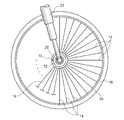
図1は、本実施形態のインホイールモータを適用した車両の車輪部分の拡大図である。インホイールモータ10は、円筒状のハブ12の内部にモータを内蔵するもので、ハブ12の外周部には放射線状に延びる複数のスポーク14の一端側が固定されている。また、スポーク14の他端側は、タイヤ部16を支持するリム18に固定されている。リム18は、ハブ12とスポーク14で結合されて車輪の骨格を形成する。また、ハブ12から突出する第1固定軸部材20(図1の場合、ハブ12の片側から突出する第1固定軸部材20のみを図示)が車両のフレームの一部であるフォーク22に固定支持されている。したがって、ハブ12、スポーク14、タイヤ部16、リム18からなる車輪は第1固定軸部材20および第1固定軸部材20と対をなす第2固定軸部材を中心に回転するように構成されている。   FIG. 1 is an enlarged view of a wheel portion of a vehicle to which the in-wheel motor of the present embodiment is applied. The in-wheel motor 10 incorporates a motor inside a cylindrical hub 12, and one end side of a plurality of spokes 14 extending radially is fixed to the outer periphery of the hub 12. Further, the other end side of the spoke 14 is fixed to a rim 18 that supports the tire portion 16. The rim 18 is joined to the hub 12 and the spoke 14 to form a wheel skeleton. Further, a first fixed shaft member 20 protruding from the hub 12 (in the case of FIG. 1, only the first fixed shaft member 20 protruding from one side of the hub 12 is shown) is fixedly supported on a fork 22 which is a part of the vehicle frame. Has been. Therefore, the wheel including the hub 12, the spoke 14, the tire portion 16, and the rim 18 is configured to rotate around the first fixed shaft member 20 and the second fixed shaft member paired with the first fixed shaft member 20. Yes.

なお、図1の場合、車輪は、ハブ12、スポーク14、タイヤ部16、リム18を含む、いわゆるスポークホイールを示しているが、スポーク14の代わりに円板を用いた、いわゆるディスクホイールでもよい。   In the case of FIG. 1, the wheel is a so-called spoke wheel including the hub 12, the spoke 14, the tire portion 16, and the rim 18, but a so-called disc wheel using a disk instead of the spoke 14 may be used. .

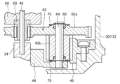
図2は、インホイールモータ10の内部構造を説明するための断面図である。インホイールモータ10は大別して、ハブ12と、このハブ12の左右から突出する第1固定軸部材20と第2固定軸部材24と、ハブ12の内部に収納されたモータ部26、減速機構28とで構成されている。   FIG. 2 is a cross-sectional view for explaining the internal structure of the in-wheel motor 10. The in-wheel motor 10 is roughly divided into a hub 12, a first fixed shaft member 20 and a second fixed shaft member 24 projecting from the left and right of the hub 12, a motor unit 26 housed in the hub 12, and a speed reduction mechanism 28. It consists of and.

ハブ12は、外周に車輪が結合されるべき円筒形状の部品で、本実施形態の場合、ハブ12は、一方面に開口部30aを有するカップ形状の第1部材30と、開口部30aを封止する円板形状または蓋形状の第2部材32とで構成される。ハブ12は鉄や鋳物、ステンレス鋼等で形成することができる。なお、図2の場合、第1部材30は円筒状の胴部と、その胴部を塞ぐ底部とからなるカップ形状の一体部品としているが、これに限られない。例えば、胴部と底部とを別々に形成して結合するようにしてもよい。胴部と底部との結合方法としては溶接やネジ結合等既知の結合方法を用いることができる。このように、ハブ12が蓋形状の第2部材32を含むことにより、第2部材32の着脱により内部の露出が容易になり、組立性の向上やメンテナンス時の作業性の向上に寄与できる。なお、ハブ12の完全な内部気密は必要ないが、水等が浸入しない程度の防水レベルを実現しておくことが好ましい。例えば、第1部材30と第2部材32との接合部分にOリング等を介在させて防水シール機能を持たせることが好ましい。また、回転側である第2部材32と固定側である第1固定軸部材20との間や、回転側である第1部材30と固定側である第2固定軸部材24との間にラビリンスを設け、液体の浸入を抑制するようにしてもよい。   The hub 12 is a cylindrical part to which a wheel is to be coupled to the outer periphery. In the present embodiment, the hub 12 seals the cup-shaped first member 30 having an opening 30a on one surface and the opening 30a. It is comprised with the disk-shaped or lid-shaped 2nd member 32 to stop. The hub 12 can be formed of iron, casting, stainless steel, or the like. In the case of FIG. 2, the first member 30 is a cup-shaped integral part composed of a cylindrical body and a bottom that closes the body, but is not limited thereto. For example, the body portion and the bottom portion may be separately formed and combined. As a coupling method between the body portion and the bottom portion, a known coupling method such as welding or screw coupling can be used. As described above, when the hub 12 includes the lid-shaped second member 32, the inside of the hub 12 can be easily exposed by attaching and detaching the second member 32, which can contribute to improvement in assembling property and workability during maintenance. Although the hub 12 is not required to be completely airtight, it is preferable to achieve a waterproof level that does not allow water or the like to enter. For example, it is preferable to provide a waterproof sealing function by interposing an O-ring or the like at the joint between the first member 30 and the second member 32. Further, the labyrinth between the second member 32 on the rotating side and the first fixed shaft member 20 on the fixed side, or between the first member 30 on the rotating side and the second fixed shaft member 24 on the fixed side. May be provided to suppress the ingress of liquid.

ハブ12を構成する蓋形状の第2部材32は、当該ハブ12の回転中心と同軸となる中央部に第1固定軸部材20を貫通可能とする貫通口32aを有する。また第2部材32の貫通口32aに対応する部分には、第1固定軸部材20を軸として第2部材32、つまりハブ12を回転自在に支持する第1ベアリング34が固定されている。また、第2部材32の内部側、つまり、ハブ12の内部には、モータ部26の基台となるモータベース36が、第1固定軸部材20に固定されて配置される。図2に示すように、モータベース36には、第1固定軸部材20が貫通する軸受孔36aが形成され、第1固定軸部材20が、圧入や溶接、またはその複合処理により固着されている。したがって、モータベース36は第1固定軸部材20と一体化され、その周囲を第2部材32、すなわちハブ12が回転するように構成される。   The lid-shaped second member 32 constituting the hub 12 has a through-opening 32 a that allows the first fixed shaft member 20 to pass through a central portion that is coaxial with the rotation center of the hub 12. A second bearing 32 that supports the second member 32, that is, the hub 12 so as to be rotatable, is fixed to the portion of the second member 32 corresponding to the through-hole 32a. In addition, on the inner side of the second member 32, that is, in the hub 12, a motor base 36 that serves as a base of the motor unit 26 is fixed to the first fixed shaft member 20. As shown in FIG. 2, the motor base 36 is formed with a bearing hole 36a through which the first fixed shaft member 20 passes, and the first fixed shaft member 20 is fixed by press-fitting, welding, or a combined process thereof. . Therefore, the motor base 36 is integrated with the first fixed shaft member 20, and the second member 32, that is, the hub 12 is configured to rotate around the motor base 36.

第1固定軸部材20は、例えば鉄やステンレス鋼で形成され、図2に示すように内部にモータ部26を駆動するための信号線や電力線等の駆動ライン38を通すライン孔20aが形成されている。図2の場合、ライン孔20aは説明のため比較的大径で描いているが、駆動ライン38の配索作業ができる程度の直径があればよい。したがって、第1固定軸部材20の直径やライン孔20aの直径は、インホイールモータ10を組み付ける車両の自重やその車両の積載重量等を考慮して定められる付加加重に耐え得る剛性が得られるように適宜選択することが望ましい。また、第1固定軸部材20のハブ12内部側の端部には、後述する第3固定軸部材40を連結するための連結孔20bが形成されている。   The first fixed shaft member 20 is made of, for example, iron or stainless steel. As shown in FIG. 2, a line hole 20a through which a drive line 38 such as a signal line or a power line for driving the motor unit 26 passes is formed. ing. In the case of FIG. 2, the line hole 20 a is drawn with a relatively large diameter for the sake of explanation, but it is sufficient that the diameter is sufficient to allow the drive line 38 to be routed. Therefore, the diameter of the first fixed shaft member 20 and the diameter of the line hole 20a can provide rigidity capable of withstanding an additional load determined in consideration of the own weight of the vehicle to which the in-wheel motor 10 is assembled, the loaded weight of the vehicle, and the like. It is desirable to select as appropriate. Further, a connecting hole 20b for connecting a third fixed shaft member 40 to be described later is formed at the end of the first fixed shaft member 20 on the inner side of the hub 12.

同様に、ハブ12を構成するカップ形状の第1部材30は、当該ハブ12の回転中心と同軸となる中央部に第2固定軸部材24を貫通可能とする貫通口30bを有する。また第1部材30の貫通口30bに対応する部分には、第2固定軸部材24を軸として第1部材30、つまりハブ12を回転自在に支持する第2ベアリング42が固定されている。また、第1部材30の内部側、つまり、ハブ12の内部には、モータ部26の回転数を減速する減速機構28の一部を構成するギアケース44が、第2固定軸部材24に固定されて配置される。図2に示すように、ギアケース44には、第2固定軸部材24が貫通する軸受孔44aが形成され、第2固定軸部材24が、圧入や溶接、またはその複合処理により固着されている。第2固定軸部材24は、例えば鉄やステンレス鋼で形成され、ハブ12の内部側の端部には、後述する第3固定軸部材40を連結するための連結孔24aが形成されている。第1部材30のカップ形状の内周面には減速機構28の出力側ギア、つまり後述する遊星ギアと噛合するリング状の内歯ギア46が固定されている。前述のようにギアケース44は第2固定軸部材24に固着され一体化されているので、減速機構28の出力側ギアの回転により内歯ギア46が回転させられると、第2固定軸部材24および減速機構28の周囲を第1部材30、すなわちハブ12が回転する。なお、上述したように、ギアケース44は、第2固定軸部材24に固定されているため、遊星ギア62は第2固定軸部材24または第1固定軸部材20に対して公転を制限されるようにギアケース44に支持されることになる。   Similarly, the cup-shaped first member 30 constituting the hub 12 has a through-opening 30 b that allows the second fixed shaft member 24 to pass through a central portion that is coaxial with the rotation center of the hub 12. A second bearing 42 that rotatably supports the first member 30, that is, the hub 12, is fixed to a portion corresponding to the through hole 30 b of the first member 30 with the second fixed shaft member 24 as an axis. A gear case 44 constituting a part of a speed reduction mechanism 28 for reducing the rotational speed of the motor unit 26 is fixed to the second fixed shaft member 24 on the inner side of the first member 30, that is, in the hub 12. To be placed. As shown in FIG. 2, the gear case 44 is formed with a bearing hole 44a through which the second fixed shaft member 24 passes, and the second fixed shaft member 24 is fixed by press-fitting, welding, or a combined process thereof. . The second fixed shaft member 24 is made of, for example, iron or stainless steel, and a connection hole 24 a for connecting a third fixed shaft member 40 described later is formed at the inner end of the hub 12. A ring-shaped internal gear 46 that meshes with the output side gear of the speed reduction mechanism 28, that is, a planetary gear described later, is fixed to the cup-shaped inner peripheral surface of the first member 30. As described above, since the gear case 44 is fixed and integrated with the second fixed shaft member 24, when the internal gear 46 is rotated by the rotation of the output side gear of the speed reduction mechanism 28, the second fixed shaft member 24 is rotated. The first member 30, that is, the hub 12 rotates around the speed reduction mechanism 28. As described above, since the gear case 44 is fixed to the second fixed shaft member 24, the planetary gear 62 is restricted from revolving with respect to the second fixed shaft member 24 or the first fixed shaft member 20. Thus, it is supported by the gear case 44.

モータ部26は、モータベース36、ステータコア48、コイル50、ロータコア52、マグネット54等を含んで構成されている。
本実施形態の場合、モータベース36はカップ形状であり、金属や樹脂またはその複合により形成されている。カップ形状のモータベース36は、コイル50が巻回されたステータコア48と、リング状のマグネット54が固定されたロータコア52を内部に収納する。
The motor unit 26 includes a motor base 36, a stator core 48, a coil 50, a rotor core 52, a magnet 54, and the like.
In the case of this embodiment, the motor base 36 has a cup shape and is formed of metal, resin, or a composite thereof. The cup-shaped motor base 36 accommodates therein a stator core 48 around which the coil 50 is wound and a rotor core 52 to which a ring-shaped magnet 54 is fixed.

ステータコア48は、ケイ素鋼板等の磁性材を積層した後に、表面に電着塗装や粉体塗装等による絶縁コーディングを施して形成される。ステータコア48は複数のネジ56等の締結手段によってモータベース36に固定されている。また、ステータコア48は、内方向に突出する複数の突極(図示せず)を有するリング状であり、各突極にはコイル50が巻回されている。コイル50の巻き線端末は、モータベース36の底面から引き込まれている駆動ライン38とコネクタ等を介して接続され、コイル50は磁界の発生に必要な電力の供給を受ける。   The stator core 48 is formed by laminating a magnetic material such as a silicon steel plate and then subjecting the surface to insulation coating by electrodeposition coating or powder coating. The stator core 48 is fixed to the motor base 36 by fastening means such as a plurality of screws 56. The stator core 48 has a ring shape having a plurality of salient poles (not shown) projecting inward, and a coil 50 is wound around each salient pole. The winding end of the coil 50 is connected to a drive line 38 drawn from the bottom surface of the motor base 36 via a connector or the like, and the coil 50 is supplied with electric power necessary for generating a magnetic field.

ロータコア52は、ステータコア48およびコイル50を含むステータの内周領域に配置されている。ロータコア52は、鉄を切削加工などによりリング形状に加工して、外周面側にリング状のマグネット54を固定している。内周面側は、第1固定軸部材20に内輪側が圧入固定された第3ベアリング58の外輪が圧入固定されている。所定の駆動回路により3相の略正弦波状の電流がコイル50に通電されると、コイル50はステータコア48の突極に回転磁界を発生する。そして、マグネット54の駆動用磁極と回転磁界との相互作用により回転駆動力が生じて、ロータコア52が第1固定軸部材20の周囲を電流量に応じた速度で回転可能となる。   The rotor core 52 is disposed in the inner peripheral region of the stator including the stator core 48 and the coil 50. The rotor core 52 is obtained by processing iron into a ring shape by cutting or the like, and fixing a ring-shaped magnet 54 on the outer peripheral surface side. On the inner peripheral surface side, an outer ring of a third bearing 58 in which the inner ring side is press-fitted and fixed to the first fixed shaft member 20 is press-fitted and fixed. When a three-phase substantially sinusoidal current is passed through the coil 50 by a predetermined drive circuit, the coil 50 generates a rotating magnetic field at the salient pole of the stator core 48. Then, a rotational driving force is generated by the interaction between the driving magnetic pole of the magnet 54 and the rotating magnetic field, and the rotor core 52 can rotate around the first fixed shaft member 20 at a speed corresponding to the amount of current.

なお、本実施形態の場合、モータベース36をカップ形状とすることで、ステータコア48およびコイル50、すなわちステータの少なくとも一部をハブ12内部に露出させるように露出口36bを形成している。モータ部26の駆動時にはコイル50で発熱する。コイル50で発生した熱はステータコア48を介してモータベース36に伝わり放熱されるが、本実施形態に場合、モータベース36が露出口36bを有しコイル50を含むステータの一方面をハブ12内部に露出させることで、放熱効果を高めている。このように、露出口36bを形成することで、モータ部26全体をケーシングで覆う場合に比べて放熱効率が高まり、発熱によるモータ性能の低下が抑制できる。また、露出口36bはモータ駆動時に回転駆動している減速機構28側に開口しているので、減速機構28の回転駆動による熱の拡散や冷却が可能になり、放熱効率をさらに高めることができる。   In the present embodiment, the motor base 36 is formed in a cup shape, so that the exposure opening 36 b is formed so that at least a part of the stator core 48 and the coil 50, that is, the stator is exposed inside the hub 12. The coil 50 generates heat when the motor unit 26 is driven. The heat generated in the coil 50 is transferred to the motor base 36 through the stator core 48 and radiated. In this embodiment, the motor base 36 has an exposure port 36b and one surface of the stator including the coil 50 is connected to the inside of the hub 12. The heat dissipation effect is enhanced by exposing to the surface. Thus, by forming the exposure port 36b, compared with the case where the motor part 26 whole is covered with a casing, heat dissipation efficiency increases and it can suppress the fall of the motor performance by heat_generation | fever. Further, since the exposure port 36b is opened to the speed reduction mechanism 28 that is rotationally driven when the motor is driven, heat can be diffused and cooled by the rotational drive of the speed reduction mechanism 28, and the heat dissipation efficiency can be further increased. .

減速機構28は、ギアケース44、太陽ギア60、複数の遊星ギア62、内歯ギア46等を含んで構成される。
第2固定軸部材24に固定されたギアケース44には、遊星ギア62を支持するギア固定軸64が複数植設されている。このギア固定軸64は遊星ギア62を回転自在に支持する。遊星ギア62は、第1固定軸部材20および第2固定軸部材24と同軸上に配置された太陽ギア60を中心として等間隔で配置され、相互の遊星ギア62の位置が偏らないようにしている。このように配置することで、各遊星ギア62に均等にトルクがかかるようにしている。つまり、特定の遊星ギア62に偏ったストレスがかからないようして遊星ギア62のスムーズな回転や破損抑制を実現している。そのため、遊星ギア62は最低2以上配置する必要がある。なお、遊星ギア62の数は、数が多くなれば個々の遊星ギア62にかかる負荷を低下させることができるので、インホイールモータ10を適用する車両で求められるトルクに応じて適宜選択することが望ましい。つまり、遊星ギア62は2個以上であり、内歯ギア46の内周側に収納できる数から適宜選択することができる。ただし、遊星ギア62の数が増えるほど部品点数が増えると共に製造工数がかかる。本出願人は、シミュレーションの結果、遊星ギア62の数が5以下であれば、製造工数は実用上で障害とならないことを確認した。したがって、遊星ギア62の個数は2〜5個とすることが望ましく、個々の遊星ギア62の負荷軽減と製造工数のバランスから本実施形態においては、遊星ギア62の数の最適値は3個としている。なお、図2においては遊星ギア62が2個見えている状態を図示している。
The speed reduction mechanism 28 includes a gear case 44, a sun gear 60, a plurality of planetary gears 62, an internal gear 46, and the like.
A plurality of gear fixed shafts 64 that support the planetary gears 62 are implanted in the gear case 44 fixed to the second fixed shaft member 24. The gear fixed shaft 64 supports the planetary gear 62 in a freely rotatable manner. The planetary gears 62 are arranged at equal intervals around the sun gear 60 arranged coaxially with the first fixed shaft member 20 and the second fixed shaft member 24 so that the positions of the planetary gears 62 are not biased. Yes. By arranging in this way, each planetary gear 62 is equally torqued. That is, smooth rotation and damage suppression of the planetary gear 62 are realized so that no stress is applied to the specific planetary gear 62. Therefore, it is necessary to arrange at least two planetary gears 62. The number of planetary gears 62 can be appropriately selected according to the torque required for the vehicle to which the in-wheel motor 10 is applied because the load on each planetary gear 62 can be reduced as the number increases. desirable. That is, the number of planetary gears 62 is two or more, and can be appropriately selected from the number that can be accommodated on the inner peripheral side of the internal gear 46. However, as the number of planetary gears 62 increases, the number of parts increases and the number of manufacturing steps increases. As a result of simulation, the present applicant confirmed that the number of man-hours for manufacturing is not an obstacle to practical use if the number of planetary gears 62 is 5 or less. Therefore, it is desirable that the number of planetary gears 62 be 2 to 5, and in the present embodiment, the optimum number of planetary gears 62 is set to 3 in view of the load reduction of each planetary gear 62 and the balance of manufacturing man-hours. Yes. Note that FIG. 2 shows a state where two planetary gears 62 are visible.

前述したように、第1固定軸部材20には連結孔20bが形成され、第2固定軸部材24には連結孔24aが形成されている。そして、第3固定軸部材40が連結孔20bおよび連結孔24aに挿入され第1固定軸部材20と第2固定軸部材24とをそれらの軸線上で連結している。第1固定軸部材20と第2固定軸部材24を第3固定軸部材40によって軸線上で直結することによって、第1固定軸部材20と第2固定軸部材24との同軸精度を向上させることができる。つまり、ハブ12が回転したときの同軸性能に起因する振動を抑制できると共に、振動に伴う異音や騒音の発生も抑制できる。また、第1固定軸部材20と第2固定軸部材24を第3固定軸部材40によって直結することにより、第1固定軸部材20と第2固定軸部材24を1本の固定軸として構成している場合と等価となり、固定軸全体としての軸剛性が向上できる。その結果、車両自重や搭載重量に起因する部材の歪みを抑制すると共に同軸精度の維持が可能となり、振動、異音、騒音の抑制に寄与できる。第1固定軸部材20および第2固定軸部材24と第3固定軸部材40との接合は、圧入、溶接、接着等が利用可能であり、それらを単独で利用したり組み合わせて利用することができる。また、第1固定軸部材20、第2固定軸部材24、第3固定軸部材40を接続した場合の同軸精度の許容範囲内であれば、第1固定軸部材20および第2固定軸部材24と第3固定軸部材40を隙間嵌めによって接合してもよい。この場合、メンテナンス時の分解が容易になり作業性を向上できる。   As described above, the first fixed shaft member 20 has the connection hole 20b, and the second fixed shaft member 24 has the connection hole 24a. The third fixed shaft member 40 is inserted into the connecting hole 20b and the connecting hole 24a, and connects the first fixed shaft member 20 and the second fixed shaft member 24 on their axes. By directly connecting the first fixed shaft member 20 and the second fixed shaft member 24 on the axis by the third fixed shaft member 40, the coaxial accuracy between the first fixed shaft member 20 and the second fixed shaft member 24 is improved. Can do. That is, the vibration caused by the coaxial performance when the hub 12 rotates can be suppressed, and the generation of abnormal noise and noise accompanying the vibration can also be suppressed. Further, the first fixed shaft member 20 and the second fixed shaft member 24 are directly connected by the third fixed shaft member 40, whereby the first fixed shaft member 20 and the second fixed shaft member 24 are configured as one fixed shaft. As a result, the rigidity of the fixed shaft as a whole can be improved. As a result, the distortion of the member due to the vehicle's own weight or the mounted weight can be suppressed and the coaxial accuracy can be maintained, thereby contributing to the suppression of vibration, abnormal noise, and noise. For joining the first fixed shaft member 20 and the second fixed shaft member 24 and the third fixed shaft member 40, press-fitting, welding, adhesion, or the like can be used, and these can be used alone or in combination. it can. If the first fixed shaft member 20, the second fixed shaft member 24, and the third fixed shaft member 40 are within the allowable range of coaxial accuracy when connected, the first fixed shaft member 20 and the second fixed shaft member 24 are used. The third fixed shaft member 40 may be joined by a clearance fit. In this case, disassembly at the time of maintenance becomes easy and workability can be improved.

第3固定軸部材40は、第1固定軸部材20や第2固定軸部材24と同様に鉄やステンレス鋼で形成することができる。この第3固定軸部材40は、リング状のロータコア52の内周側と第3ベアリング58の外輪とを跨ぐように固定されたギアホルダ66を回転自在に支持している。このギアホルダ66には第3固定軸部材40を回転中心とする太陽ギア60が固定されている。つまり、ロータコア52が回転することにより太陽ギア60が回転する。前述したように、太陽ギア60には、複数の遊星ギア62が噛合している。遊星ギア62は、太陽ギア60と噛合する第1遊星ギア62aと、内歯ギア46と噛合する第2遊星ギア62bとで構成されている。第1遊星ギア62aと第2遊星ギア62bは、いずれもギア固定軸64を中心軸として回転する。第1遊星ギア62aと第2遊星ギア62bは別々に形成されてギア固定軸64に固定されてもよいし、第1遊星ギア62aと第2遊星ギア62bを一体で形成してギア固定軸64に固定してもよい。   Similar to the first fixed shaft member 20 and the second fixed shaft member 24, the third fixed shaft member 40 can be formed of iron or stainless steel. The third fixed shaft member 40 rotatably supports a gear holder 66 fixed so as to straddle the inner peripheral side of the ring-shaped rotor core 52 and the outer ring of the third bearing 58. A sun gear 60 having the third fixed shaft member 40 as the rotation center is fixed to the gear holder 66. In other words, the sun gear 60 rotates as the rotor core 52 rotates. As described above, the sun gear 60 is engaged with the plurality of planetary gears 62. The planetary gear 62 includes a first planetary gear 62 a that meshes with the sun gear 60 and a second planetary gear 62 b that meshes with the internal gear 46. Both the first planetary gear 62a and the second planetary gear 62b rotate around the gear fixed shaft 64 as a central axis. The first planetary gear 62a and the second planetary gear 62b may be formed separately and fixed to the gear fixed shaft 64, or the first planetary gear 62a and the second planetary gear 62b may be formed integrally to form the gear fixed shaft 64. It may be fixed to.

本発明者らは、各種シミュレーションにより、減速機構28の減速比は例えば6〜21が本実施形態のインホイールモータ10において好適であることを確認した。
減速比は、太陽ギア60の歯数をZa、内歯ギア46の歯数をZc、第1遊星ギア62aの歯数をZ1、第2遊星ギア62bの歯数をZ2とした場合、以下のようになる。
減速比≒(Z1/Za)×(Zc/Z2)
ここで、噛み合うギアの歯の大きさ、つまり太陽ギア60と第1遊星ギア62a及び第2遊星ギア62bと内歯ギア46の歯の大きさは一致させることが一般的であるので、各ギアの歯数は対応するギアの円周の長さに比例すると見なせる。したがって、ギアの基準ピッチ円直径を用いた以下の計算式で減速比を簡易的に表現できる。つまり、太陽ギア60の基準ピッチ円直径をDa、内歯ギア46の基準ピッチ円直径をDc、第1遊星ギア62aの基準ピッチ円直径をD1、第2遊星ギア62bの基準ピッチ円直径をD2とした場合、以下のようになる。
減速比≒(D1/Da)×(Dc/D2)
ここで、発明者らは本実施形態のインホイールモータ10の構成における太陽ギア60基準ピッチ円直径の下限値について、太陽ギア60の必要軸強度やインホイールモータ10全体の組み立て作業性等を考慮して検討した。その結果、Da=11.0mmを下限値として、D1=50.0mm、D2=16.2mm、Dc=77.2mmに設定することで、インホイールモータ10に要求される性能を維持できることを確認した。この場合の減速比は、21.7になった。
The present inventors have confirmed through various simulations that the reduction ratio of the speed reduction mechanism 28 is preferably 6 to 21 in the in-wheel motor 10 of the present embodiment, for example.
The reduction ratio is as follows when the number of teeth of the sun gear 60 is Za, the number of teeth of the internal gear 46 is Zc, the number of teeth of the first planetary gear 62a is Z1, and the number of teeth of the second planetary gear 62b is Z2. It becomes like this.
Reduction ratio ≒ (Z1 / Za) x (Zc / Z2)
Here, since the sizes of the teeth of the meshing gears, that is, the sizes of the teeth of the sun gear 60, the first planetary gear 62a, and the second planetary gear 62b, and the internal gear 46 are generally the same, The number of teeth can be considered to be proportional to the circumference of the corresponding gear. Therefore, the reduction ratio can be simply expressed by the following calculation formula using the reference pitch circle diameter of the gear. That is, the reference pitch circle diameter of the sun gear 60 is Da, the reference pitch circle diameter of the internal gear 46 is Dc, the reference pitch circle diameter of the first planetary gear 62a is D1, and the reference pitch circle diameter of the second planetary gear 62b is D2. When it becomes, it becomes as follows.
Reduction ratio ≒ (D1 / Da) x (Dc / D2)
Here, the inventors consider the required shaft strength of the sun gear 60 and the assembly workability of the entire in-wheel motor 10 for the lower limit value of the reference pitch circle diameter of the sun gear 60 in the configuration of the in-wheel motor 10 of the present embodiment. And examined. As a result, it is confirmed that the performance required for the in-wheel motor 10 can be maintained by setting D1 = 50.0 mm, D2 = 16.2 mm, and Dc = 77.2 mm with Da = 11.0 mm as the lower limit. did. The reduction ratio in this case was 21.7.

また、発明者らは本実施形態のインホイールモータ10の構成における太陽ギア60基準ピッチ円直径の上限値について、インホイールモータ10のサイズや重量、ハブ12の内部スペースの制限、インホイールモータ10全体の組み立て作業性等を考慮して検討した。その結果、Da=27.6mmを上限値として、D1=33.4mm、D2=16.2mm、Dc=77.2mmに設定することで、インホイールモータ10に要求されるサイズや重量の制限を満たすことを確認した。この場合の減速比は、5.77になった。   Further, the inventors set the size and weight of the in-wheel motor 10, the internal space of the hub 12, the in-wheel motor 10, and the upper limit value of the sun gear 60 reference pitch circle diameter in the configuration of the in-wheel motor 10 of the present embodiment. Considered the whole assembly workability. As a result, by setting Da = 27.6 mm as an upper limit value and setting D1 = 33.4 mm, D2 = 16.2 mm, and Dc = 77.2 mm, the size and weight restrictions required for the in-wheel motor 10 are reduced. Confirmed to meet. The reduction ratio in this case was 5.77.

また、発明者らは、Da=13.2mm、D1=47.8mm、D2=16.2mm、Dc=77.2mmが、太陽ギア60の軸強度やインホイールモータ10全体としての組み立て作業性、サイズや重量の制限をバランスよく満たす最適値であることを確認した。そして、この場合の減速比は17.3になった。このように、減速比については、減速比6〜21の範囲で、インホイールモータ10を搭載する車両の種類や用途により太陽ギア60、第1遊星ギア62a、第2遊星ギア62b、内歯ギア46の基準ピッチ円直径や歯数を適宜選択して決定することが望ましい。   In addition, the inventors have Da = 13.2 mm, D1 = 47.8 mm, D2 = 16.2 mm, and Dc = 77.2 mm, the shaft strength of the sun gear 60 and the assembly workability of the in-wheel motor 10 as a whole, It was confirmed that the optimum value satisfies the size and weight restrictions in a well-balanced manner. In this case, the reduction ratio is 17.3. As described above, the reduction ratio is within the range of 6 to 21, and the sun gear 60, the first planetary gear 62a, the second planetary gear 62b, and the internal gear depending on the type and application of the vehicle on which the in-wheel motor 10 is mounted. It is desirable to select and determine the 46 standard pitch circle diameter and the number of teeth as appropriate.

ところで、図2に示すように、本実施形態のインホイールモータ10は、減速機構28を構成する太陽ギア60の中央部に貫通口66aを有し、この貫通口66aを第3固定軸部材40が貫通して第1固定軸部材20と第2固定軸部材24とを軸線上で連結している。その結果、他の構成部品の干渉を受けることなく、また、ハブ12内部の構造の複雑化を招くことなく、第1固定軸部材20と第2固定軸部材24を直結して、第1固定軸部材20と第2固定軸部材24との同軸精度を向上させると共に、軸剛性を向上させている。   By the way, as shown in FIG. 2, the in-wheel motor 10 of this embodiment has the through-hole 66a in the center part of the sun gear 60 which comprises the deceleration mechanism 28, and this through-hole 66a is used for the 3rd fixed shaft member 40. Penetrates to connect the first fixed shaft member 20 and the second fixed shaft member 24 on the axis. As a result, the first fixed shaft member 20 and the second fixed shaft member 24 are directly connected to each other without receiving interference from other components and without complicating the internal structure of the hub 12. While improving the coaxial precision of the shaft member 20 and the 2nd fixed shaft member 24, shaft rigidity is improved.

このように構成されるインホイールモータ10の動作を説明する。
図示しない車両に設けられたアクセル装置の開度を調整することにより、駆動回路(不図示)から3相の略正弦波状の電流が駆動ライン38を介してコイル50に通電される。その結果、コイル50はステータコア48の突極に回転磁界を発生する。そして、マグネット54の駆動用磁極と回転磁界との相互作用により回転駆動力が生じて、ロータコア52を回転させる。ロータコア52は、ギアホルダ66を介して太陽ギア60に接続されているので、ロータコア52と太陽ギア60は同速で回転する。太陽ギア60は、遊星ギア62の第1遊星ギア62aと噛合し、第1遊星ギア62aは、第2遊星ギア62bと同軸に接合され、この第2遊星ギア62bが内歯ギア46と噛合している。したがって、ロータコア52の回転により内歯ギア46が固定された第1部材30が回転する。第1部材30と第2部材32は、ネジ68等の締結部材によってハブ12として一体化されていて、第1固定軸部材20および第2固定軸部材24を固定の回転軸として回転する。つまり、第1固定軸部材20と第2固定軸部材24とが固定された車体に対して、ハブ12、つまり車輪が回転して車両の走行を実現する。
The operation of the in-wheel motor 10 configured as described above will be described.
By adjusting the opening of an accelerator device provided in a vehicle (not shown), a three-phase substantially sinusoidal current is passed through the drive line 38 from a drive circuit (not shown). As a result, the coil 50 generates a rotating magnetic field at the salient pole of the stator core 48. Then, a rotational driving force is generated by the interaction between the driving magnetic pole of the magnet 54 and the rotating magnetic field, and the rotor core 52 is rotated. Since the rotor core 52 is connected to the sun gear 60 via the gear holder 66, the rotor core 52 and the sun gear 60 rotate at the same speed. The sun gear 60 meshes with the first planetary gear 62a of the planetary gear 62, the first planetary gear 62a is coaxially joined with the second planetary gear 62b, and the second planetary gear 62b meshes with the internal gear 46. ing. Accordingly, the first member 30 to which the internal gear 46 is fixed is rotated by the rotation of the rotor core 52. The first member 30 and the second member 32 are integrated as a hub 12 by a fastening member such as a screw 68, and rotate using the first fixed shaft member 20 and the second fixed shaft member 24 as fixed rotation shafts. That is, the hub 12, that is, the wheels rotate with respect to the vehicle body to which the first fixed shaft member 20 and the second fixed shaft member 24 are fixed, thereby realizing the traveling of the vehicle.

図3(a)〜(c)は、第1固定軸部材20と第2固定軸部材24と第3固定軸部材40の連結構造の他の構造例を説明する説明図である。図2の場合、第1固定軸部材20と第2固定軸部材24と第3固定軸部材40とは、それぞれ別部品として形成して、圧入や溶接、接着等の接合方法を単独または組み合わせて用いて直結した例を示した。図3(a)の例は、第1固定軸部材20と第3固定軸部材40を一体形成して固定軸70とした例である。固定軸70の第3固定軸部材40側は、第2固定軸部材24の連結孔24aに圧入や溶接、接着等の接合方法を単独または組み合わせて用いて直結する。   FIGS. 3A to 3C are explanatory views for explaining another structural example of the connection structure of the first fixed shaft member 20, the second fixed shaft member 24, and the third fixed shaft member 40. In the case of FIG. 2, the first fixed shaft member 20, the second fixed shaft member 24, and the third fixed shaft member 40 are formed as separate parts, and the joining methods such as press-fitting, welding, and bonding are used alone or in combination. An example of direct connection was shown. The example of FIG. 3A is an example in which the first fixed shaft member 20 and the third fixed shaft member 40 are integrally formed to form the fixed shaft 70. The third fixed shaft member 40 side of the fixed shaft 70 is directly connected to the connection hole 24a of the second fixed shaft member 24 by using a joining method such as press-fitting, welding, or adhesion alone or in combination.

同様に、図3(b)の例は、第2固定軸部材24と第3固定軸部材40を一体形成して固定軸72とした例である。固定軸72の第3固定軸部材40側は、第1固定軸部材20の連結孔20bに圧入や溶接、接着等の接合方法を単独または組み合わせて用いて直結する。このように、第1固定軸部材20と第2固定軸部材24のいずれか一方に第3固定軸部材40を一体的に形成することにより、各固定軸を別部品とする場合に比べて部品点数や製造工数の低減、および軸剛性の向上等を図ることができる。   Similarly, the example of FIG. 3B is an example in which the second fixed shaft member 24 and the third fixed shaft member 40 are integrally formed to form the fixed shaft 72. The third fixed shaft member 40 side of the fixed shaft 72 is directly connected to the connection hole 20b of the first fixed shaft member 20 by using a joining method such as press-fitting, welding, or adhesion alone or in combination. As described above, the third fixed shaft member 40 is integrally formed on one of the first fixed shaft member 20 and the second fixed shaft member 24, so that the components can be compared with the case where each fixed shaft is a separate component. It is possible to reduce the number of points and manufacturing man-hours and improve the shaft rigidity.

図3(c)は、第1固定軸部材20、第2固定軸部材24、第3固定軸部材40を一体として固定軸74とした例である。この場合、図3(a)、図3(b)の例よりさらに部品点数や製造工数の低減、および軸剛性の向上等を図ることができる。ただし、図3(c)の場合、第3固定軸部材40に相当する部分でギアホルダ66および太陽ギア60を回転自在に軸支する必要がある。そのような構造の場合の組立を可能にするため、第3固定軸部材40に相当する部分を第1固定軸部材20および第2固定軸部材24と同径またはそれより大径にする必要がある。第3固定軸部材40相当部分の直径を大きくすることにより、太陽ギア60の基準ピッチ円直径を大きくし、遊星ギア62の基準ピッチ円直径を小さくする必要が生じるため、減速比とのバランスを考慮して固定軸74の採用を決定することが好ましい。   FIG. 3C is an example in which the first fixed shaft member 20, the second fixed shaft member 24, and the third fixed shaft member 40 are integrated into a fixed shaft 74. In this case, it is possible to further reduce the number of parts and the number of manufacturing steps, improve the shaft rigidity, and the like from the example of FIGS. 3 (a) and 3 (b). However, in the case of FIG. 3C, it is necessary to rotatably support the gear holder 66 and the sun gear 60 at a portion corresponding to the third fixed shaft member 40. In order to enable assembly in the case of such a structure, it is necessary to make the portion corresponding to the third fixed shaft member 40 the same diameter or larger than the first fixed shaft member 20 and the second fixed shaft member 24. is there. By increasing the diameter of the portion corresponding to the third fixed shaft member 40, it becomes necessary to increase the reference pitch circle diameter of the sun gear 60 and to reduce the reference pitch circle diameter of the planetary gear 62. It is preferable to determine the use of the fixed shaft 74 in consideration of the above.

ところで、図2に示すインホイールモータ10の構造において、遊星ギア62はギア固定軸64の周囲をベアリング等を介することなく回転する構造を採用している。そのため、62の上下の支持端面が被支持面と摺動する。その結果、回転時にギア固定軸64に支持される遊星ギア62の支持端面が早期に摩耗する場合がある。本実施形態では、図4に示すように、第2固定軸部材24に固定されたギアケース44に植設されたギア固定軸64に、当該ギア固定軸64の軸方向に遊星ギア62が移動することを規制するリング状の一対のワッシャ76を設け、遊星ギア62を挟み位置決めしている。そして、このワッシャ76は、遊星ギア62と共に回転するように構成している。例えば、ワッシャ76に形成した係合爪を遊星ギア62の端面と係合させるようにしている。その結果、遊星ギア62の回転時に、ワッシャ76がギアケース44やギア固定軸64の固定部と接触させて、ワッシャ76が先に摩耗するように構成している。したがって、インホイールモータ10のメンテナンスはワッシャ76の摩耗に基づいて実施すると共に、交換部品はワッシャ76のみにできるように構成している。その結果、インホイールモータ10のメンテナンスコストの低減ができる。   In the structure of the in-wheel motor 10 shown in FIG. 2, the planetary gear 62 employs a structure that rotates around the gear fixed shaft 64 without using a bearing or the like. Therefore, the upper and lower support end surfaces 62 slide on the supported surface. As a result, the support end surface of the planetary gear 62 supported by the gear fixed shaft 64 may be worn at an early stage during rotation. In the present embodiment, as shown in FIG. 4, the planetary gear 62 moves in the axial direction of the gear fixed shaft 64 to the gear fixed shaft 64 implanted in the gear case 44 fixed to the second fixed shaft member 24. A pair of ring-shaped washers 76 for restricting the operation are provided, and the planetary gear 62 is sandwiched and positioned. The washer 76 is configured to rotate together with the planetary gear 62. For example, the engaging claw formed on the washer 76 is engaged with the end face of the planetary gear 62. As a result, when the planetary gear 62 is rotated, the washer 76 is brought into contact with the fixed portion of the gear case 44 and the gear fixing shaft 64 so that the washer 76 is worn first. Therefore, the maintenance of the in-wheel motor 10 is performed based on the wear of the washer 76, and the replacement part can be made only by the washer 76. As a result, the maintenance cost of the in-wheel motor 10 can be reduced.

このワッシャ76は、例えばステンレス鋼、鉄、銅材等の金属を用いて形成することができる。また、ワッシャ76は、自己潤滑性のある材料で形成してもよい。例えば、ワッシャ76をPEEK(ポリエーテル・エーテル・ケトン)で形成してもよい。PEEKは、熱可塑性の超耐熱高分子樹脂であり、耐疲労性・耐衝撃性・耐クリープ性に優れ、耐薬品性では濃硫酸以外は使用可能であり、ガス・金属イオンの溶出が少ない材料であり、耐発熱性、耐衝撃性、耐腐食性等が要求されるインホイールモータ10への使用に適している。ワッシャ76は、その厚みを調整したり、積層したりして耐久性を調整してもよい。   The washer 76 can be formed using a metal such as stainless steel, iron, or copper. The washer 76 may be formed of a self-lubricating material. For example, the washer 76 may be formed of PEEK (polyether ether ketone). PEEK is a thermoplastic super heat-resistant polymer resin that has excellent fatigue resistance, impact resistance, and creep resistance, and that can be used for chemical resistance other than concentrated sulfuric acid, and has little elution of gas and metal ions. It is suitable for use in an in-wheel motor 10 that requires heat resistance, impact resistance, corrosion resistance, and the like. The washer 76 may be adjusted in durability by adjusting its thickness or by laminating.

また、図5(a)は、遊星ギア62の支持安定性を向上させるための弾性ブラケット78の一例を示す斜視図である。弾性ブラケット78は、ギアケース44と遊星ギア62との間に弾性力を付与する弾性部材として機能し、遊星ギア62を所定方向、例えば、ギアケース44から離間する方向に付勢するような付勢力を発生する。弾性ブラケット78は例えば板状のバネ鋼をプレス加工等で打ち抜きおよび変形させることで形成することができる。図5(b)は、弾性ブラケット78をギアケース44と遊星ギア62の間に介在させた状態を説明する説明図である。弾性ブラケット78により遊星ギア62を一定方向(図中矢印A方向)に付勢しておくことにより、遊星ギア62をギア固定軸64の先端に装着された固定リング80等の固定部材に付勢して、遊星ギア62が回転するときのギア固定軸64の軸方向へ振動(ばたつき)を抑制する。このように遊星ギア62のギア固定軸64の軸方向への振動を抑制することにより、インホイールモータ10全体の振動抑制、異音抑制、遊星ギア62の摩耗軽減等を実現できる。   FIG. 5A is a perspective view showing an example of an elastic bracket 78 for improving the support stability of the planetary gear 62. The elastic bracket 78 functions as an elastic member that applies an elastic force between the gear case 44 and the planetary gear 62, and biases the planetary gear 62 in a predetermined direction, for example, a direction away from the gear case 44. Generate power. The elastic bracket 78 can be formed, for example, by punching and deforming a plate-shaped spring steel by pressing or the like. FIG. 5B is an explanatory diagram for explaining a state in which the elastic bracket 78 is interposed between the gear case 44 and the planetary gear 62. By energizing the planetary gear 62 in a certain direction (in the direction of arrow A in the figure) by the elastic bracket 78, the planetary gear 62 is energized to a fixing member such as a fixing ring 80 attached to the tip of the gear fixing shaft 64. Thus, vibration (flapping) is suppressed in the axial direction of the gear fixed shaft 64 when the planetary gear 62 rotates. In this way, by suppressing the vibration of the planetary gear 62 in the axial direction of the gear fixed shaft 64, it is possible to realize vibration suppression of the entire in-wheel motor 10, noise suppression, reduction of wear of the planetary gear 62, and the like.

なお、図5(b)の場合、弾性ブラケット78の上面にワッシャ76を介在させている例を示している。この場合、弾性ブラケット78は、ワッシャ76と共に遊星ギア62を付勢し、ワッシャ76と遊星ギア62が、弾性ブラケット78上で回転することになる。また。弾性ブラケット78上のワッシャ76を省略して弾性ブラケット78のみで遊星ギア62を付勢支持するようにしてもよい。この場合、弾性ブラケット78は遊星ギア62と共に回転しない。そのため、弾性ブラケット78を自己潤滑性のある材料で構成するか、弾性ブラケット78の上面に潤滑層をコーティングして、遊星ギア62の摩耗を軽減するようにしてもよい。   In the case of FIG. 5B, an example in which a washer 76 is interposed on the upper surface of the elastic bracket 78 is shown. In this case, the elastic bracket 78 urges the planetary gear 62 together with the washer 76, and the washer 76 and the planetary gear 62 rotate on the elastic bracket 78. Also. The washer 76 on the elastic bracket 78 may be omitted, and the planetary gear 62 may be biased and supported only by the elastic bracket 78. In this case, the elastic bracket 78 does not rotate with the planetary gear 62. Therefore, the elastic bracket 78 may be made of a self-lubricating material, or the upper surface of the elastic bracket 78 may be coated with a lubricating layer to reduce the wear of the planetary gear 62.

なお、図5(a)では、弾性ブラケット78はギア固定軸64が挿通できる円形の開口を有する例を示しているが、その形状は遊星ギア62に対して付勢力を発生できればよい。例えば、ギア固定軸64の挿通部をU字形状にして、ギア固定軸64の横方向から装着できるようにしてもよい。また、弾性ブラケット78を遊星ギア62の上下位置に配置してもよい。この場合、一対の弾性ブラケット78の付勢力を同じにして遊星ギア62をギア固定軸64の中央に位置させてもよい。また、付勢力を異ならせて一方側に付勢するようにしてもよい。   5A shows an example in which the elastic bracket 78 has a circular opening through which the gear fixing shaft 64 can be inserted. However, the shape of the elastic bracket 78 only needs to generate a biasing force with respect to the planetary gear 62. For example, the insertion portion of the gear fixed shaft 64 may be U-shaped so that the gear fixed shaft 64 can be mounted from the lateral direction. Further, the elastic bracket 78 may be disposed at the upper and lower positions of the planetary gear 62. In this case, the planetary gear 62 may be positioned at the center of the gear fixed shaft 64 with the urging force of the pair of elastic brackets 78 being the same. Further, the biasing force may be varied to bias to one side.

本実施形態は、車両が停止状態から最大速度までモータ部26の制御により完全カバーする電動車両に適用するインホイールモータ10の例を示した。変形例においては、例えば、ハブ12内部にクラッチ機構を設け、電動アシスト仕様にしてもよい。例えば、電動アシスト自転車の駆動部としてインホイールモータ10を利用する場合、発進時にクラッチ機構をインホイールモータ10に接続して、モータ部26によるモータアシストを行う。そして、所定の速度を超えた場合や運転者の要求があった場合にクラッチ機構を離脱させ、ペダル回転力のみで自転車を走行させるようにしてもよい。また、自転車を漕ぐ力(トルク)の検出器を回路に組み込むことによって、トルクに応じたレベルのアシストをインホイールモータ10で行うようにしてもよい。さらに、本実施形態のインホイールモータ10と他の駆動源を組み合わせて、インホイールモータ10を含む複数の駆動源を同時使用モードで使用したり、選択使用モードで使用するようにしてもよい。   In the present embodiment, an example of the in-wheel motor 10 applied to an electric vehicle that is completely covered by the control of the motor unit 26 from the stop state to the maximum speed is shown. In the modified example, for example, a clutch mechanism may be provided inside the hub 12 so as to have an electric assist specification. For example, when the in-wheel motor 10 is used as a drive unit of an electrically assisted bicycle, a clutch mechanism is connected to the in-wheel motor 10 at the time of starting, and motor assist by the motor unit 26 is performed. Then, the clutch mechanism may be disengaged when the predetermined speed is exceeded or the driver requests, and the bicycle may be driven only by the pedal rotational force. In addition, the in-wheel motor 10 may provide a level of assist corresponding to the torque by incorporating a detector (torque) for riding the bicycle into the circuit. Furthermore, the in-wheel motor 10 of this embodiment may be combined with another drive source, and a plurality of drive sources including the in-wheel motor 10 may be used in the simultaneous use mode or in the selective use mode.

なお、上述の実施形態では、インホイールモータ10を搭載する車両を特定することなく構造や効果を説明したが、このようなインホイールモータ10を適用する車両の例としては、例えば、電動二輪車、電動車椅子、モータ付きスクータ、電動台車、ゴルフカート、電動自転車等がある。このように、本実施形態のインホイールモータ10は自走タイプの車輪またはトルクアシストタイプ車輪を構成可能であり、上述した例と同様の効果を得ることができる。   In the above-described embodiment, the structure and effect have been described without specifying the vehicle on which the in-wheel motor 10 is mounted. Examples of the vehicle to which the in-wheel motor 10 is applied include, for example, an electric motorcycle, There are electric wheelchairs, motorized scooters, electric carts, golf carts, electric bicycles, and the like. Thus, the in-wheel motor 10 of this embodiment can comprise a self-propelled type wheel or a torque assist type wheel, and can obtain the same effect as the example mentioned above.

以上、実施の形態に係るインホイールモータの構成について説明した。これらの実施の形態は例示であり、本発明の原理、応用を示しているにすぎないことはいうまでもない。実施の形態には、請求の範囲に規定された本発明の思想を逸脱しない範囲において、多くの変形例や配置の変更が可能であり、またそうした変形例も本発明の範囲にあることは当業者に理解されるところである。   The configuration of the in-wheel motor according to the embodiment has been described above. These embodiments are merely examples, and it is needless to say that they merely illustrate the principles and applications of the present invention. In the embodiment, many modifications and arrangements can be made without departing from the spirit of the present invention defined in the claims, and such modifications are also within the scope of the present invention. That is understood by the contractor.

10 インホイールモータ、 12 ハブ、 20 第1固定軸部材、 24 第2固定軸部材、 28 減速機構、 30a 開口部、 30 第1部材、 30b 貫通口、 32 第2部材、 32a 貫通口、 36 モータベース、 36b 露出口、 40 第3固定軸部材、 44 ギアケース、 48 ステータコア、 52 ロータコア、 60 太陽ギア、 62 遊星ギア、 64 ギア固定軸、 66a 貫通口、 70,72,74 固定軸、 76 ワッシャ。   10 in-wheel motor, 12 hub, 20 first fixed shaft member, 24 second fixed shaft member, 28 speed reduction mechanism, 30a opening, 30 first member, 30b through port, 32 second member, 32a through port, 36 motor Base, 36b Exposed port, 40 Third fixed shaft member, 44 Gear case, 48 Stator core, 52 Rotor core, 60 Sun gear, 62 Planetary gear, 64 Gear fixed shaft, 66a Through port, 70, 72, 74 Fixed shaft, 76 Washer .

Claims (9)

外周に車輪が結合されるべき円筒形状のハブと、
前記ハブの一面側を貫通し当該ハブを回転自在に支持する第1固定軸部材と、
前記第1固定軸部材と同軸で前記ハブの他面側を貫通し当該ハブを回転自在に支持する第2固定軸部材と、
前記ハブの内部に配置され、前記第1固定軸部材が貫通すると共に前記第1固定軸部材に固定されたモータベースと、
前記モータベースに固定されたステータと、
前記ステータの内周領域に配置され、前記第1固定軸部材に回転自在に支持されたロータと、
前記第2固定軸部材と同軸となる貫通口を有すると共に前記ロータから回転力が入力されて当該ロータの回転速度を減速する減速機構と、
前記ハブの内周面に固定され、前記減速機構の出力側ギアが接続されたリング状の内歯ギアと、
前記貫通口を介して前記第1固定軸部材と前記第2固定軸部材とをそれらの軸線上で連結する第3固定軸部材と、
を含むことを特徴とするインホイールモータ。
A cylindrical hub to which a wheel should be coupled to the outer periphery;
A first fixed shaft member that passes through one side of the hub and rotatably supports the hub;
A second fixed shaft member that is coaxial with the first fixed shaft member and penetrates the other surface side of the hub and rotatably supports the hub;
A motor base disposed inside the hub, through which the first fixed shaft member passes and fixed to the first fixed shaft member;
A stator fixed to the motor base;
A rotor disposed in an inner peripheral region of the stator and rotatably supported by the first fixed shaft member;
A speed reduction mechanism that has a through-hole that is coaxial with the second fixed shaft member and receives a rotational force from the rotor to reduce the rotational speed of the rotor;
A ring-shaped internal gear fixed to the inner peripheral surface of the hub and connected to the output side gear of the speed reduction mechanism;
A third fixed shaft member for connecting the first fixed shaft member and the second fixed shaft member on their axes via the through hole;
An in-wheel motor comprising:
前記第3固定軸部材は、前記第1固定軸部材と前記第2固定軸部材の少なくとも一方と一体形成されることを特徴とする請求項1記載のインホイールモータ。   The in-wheel motor according to claim 1, wherein the third fixed shaft member is integrally formed with at least one of the first fixed shaft member and the second fixed shaft member. 前記モータベースは、前記ステータの少なくとも一部を前記ハブ内部に露出させる露出口を有することを特徴とする請求項1または請求項2記載のインホイールモータ。   The in-wheel motor according to claim 1, wherein the motor base has an exposure port that exposes at least a part of the stator inside the hub. 前記ハブは、一方面に開口部を有するカップ形状の第1部材と、前記開口部を封止する円板形状の第2部材とで構成されることを特徴とする請求項1から請求項3のいずれか1項に記載のインホイールモータ。   The said hub is comprised by the cup-shaped 1st member which has an opening part in one surface, and the disk-shaped 2nd member which seals the said opening part, The Claims 1-3 characterized by the above-mentioned. The in-wheel motor of any one of these. 前記減速機構の減速比は6〜21であることを特徴とする請求項1から請求項4のいずれか1項に記載のインホイールモータ。   The in-wheel motor according to any one of claims 1 to 4, wherein a reduction ratio of the reduction mechanism is 6 to 21. 前記減速機構は、入力側の太陽ギアとそれと噛合する複数の遊星ギアで構成され、前記遊星ギアの数が2〜5であることを特徴とする請求項1から請求項5のいずれか1項に記載のインホイールモータ。   The said reduction mechanism is comprised by the sun gear of the input side, and the several planetary gear meshing with it, The number of the said planetary gears is 2-5, The any one of Claims 1-5 characterized by the above-mentioned. In-wheel motor as described in. 前記遊星ギアは、前記第2固定軸部材に固定されたギアケースに植設されたギア固定軸に、当該ギア固定軸の軸方向の移動を規制しつつ前記遊星ギアと共に回転する一対のワッシャで挟まれて位置決めされることを特徴とする請求項6記載のインホイールモータ。   The planetary gear is a pair of washers that rotate together with the planetary gear while restricting movement of the gear fixed shaft in the axial direction on a gear fixed shaft implanted in a gear case fixed to the second fixed shaft member. The in-wheel motor according to claim 6, wherein the in-wheel motor is sandwiched and positioned. 前記ワッシャは、自己潤滑性のある材質で形成されることを特徴とする請求項7記載のインホイールモータ。   The in-wheel motor according to claim 7, wherein the washer is formed of a self-lubricating material. 前記ギアケースと前記遊星ギアとの間に弾性部材を介在させたことを特徴とする請求項7または請求項8記載のインホイールモータ。   The in-wheel motor according to claim 7, wherein an elastic member is interposed between the gear case and the planetary gear.
JP2011098672A 2011-04-26 2011-04-26 In-wheel motor Ceased JP2012228966A (en)

Priority Applications (2)

Application Number Priority Date Filing Date Title
JP2011098672A JP2012228966A (en) 2011-04-26 2011-04-26 In-wheel motor
CN2012101202463A CN102756640A (en) 2011-04-26 2012-04-18 Wheel driving apparatus

Applications Claiming Priority (1)

Application Number Priority Date Filing Date Title
JP2011098672A JP2012228966A (en) 2011-04-26 2011-04-26 In-wheel motor

Publications (2)

Publication Number Publication Date
JP2012228966A true JP2012228966A (en) 2012-11-22
JP2012228966A5 JP2012228966A5 (en) 2014-04-24

Family

ID=47430911

Family Applications (1)

Application Number Title Priority Date Filing Date
JP2011098672A Ceased JP2012228966A (en) 2011-04-26 2011-04-26 In-wheel motor

Country Status (1)

Country Link
JP (1) JP2012228966A (en)

Cited By (4)

* Cited by examiner, † Cited by third party
Publication number Priority date Publication date Assignee Title
CN103707757A (en) * 2013-12-30 2014-04-09 绍兴金道齿轮箱有限公司 Dynamic drive pallet truck and dynamic drive wheel thereof
CN103738155A (en) * 2013-12-30 2014-04-23 绍兴金道齿轮箱有限公司 Electric horizontal driving wheel assembly
KR101488507B1 (en) 2012-05-21 2015-02-02 씨스톤 테크놀로지스(주) Hub Drive Mechanism
JP2016016718A (en) * 2014-07-07 2016-02-01 ブリヂストンサイクル株式会社 Hub structure with built-in motor, and bicycle

Citations (7)

* Cited by examiner, † Cited by third party
Publication number Priority date Publication date Assignee Title
JPS61189752U (en) * 1985-05-18 1986-11-26
US5581136A (en) * 1994-12-20 1996-12-03 Li; I-Ho Auxiliary magnetic motor (AMM)
JP2003191882A (en) * 2001-10-19 2003-07-09 Yamaha Motor Co Ltd Braking device for motor-driven two-wheeled vehicle
JP2005214393A (en) * 2004-02-02 2005-08-11 Nsk Ltd Planetary gear mechanism
JP2005335536A (en) * 2004-05-27 2005-12-08 Sanyo Electric Co Ltd Hub unit for electromotive vehicle wheel, and vehicle with the hub unit
US6974399B2 (en) * 2004-02-11 2005-12-13 Chiu-Hsiang Lo Hub motor mechanism
JP2009008127A (en) * 2007-06-26 2009-01-15 Toyota Motor Corp Planetary gear device

Patent Citations (7)

* Cited by examiner, † Cited by third party
Publication number Priority date Publication date Assignee Title
JPS61189752U (en) * 1985-05-18 1986-11-26
US5581136A (en) * 1994-12-20 1996-12-03 Li; I-Ho Auxiliary magnetic motor (AMM)
JP2003191882A (en) * 2001-10-19 2003-07-09 Yamaha Motor Co Ltd Braking device for motor-driven two-wheeled vehicle
JP2005214393A (en) * 2004-02-02 2005-08-11 Nsk Ltd Planetary gear mechanism
US6974399B2 (en) * 2004-02-11 2005-12-13 Chiu-Hsiang Lo Hub motor mechanism
JP2005335536A (en) * 2004-05-27 2005-12-08 Sanyo Electric Co Ltd Hub unit for electromotive vehicle wheel, and vehicle with the hub unit
JP2009008127A (en) * 2007-06-26 2009-01-15 Toyota Motor Corp Planetary gear device

Cited By (4)

* Cited by examiner, † Cited by third party
Publication number Priority date Publication date Assignee Title
KR101488507B1 (en) 2012-05-21 2015-02-02 씨스톤 테크놀로지스(주) Hub Drive Mechanism
CN103707757A (en) * 2013-12-30 2014-04-09 绍兴金道齿轮箱有限公司 Dynamic drive pallet truck and dynamic drive wheel thereof
CN103738155A (en) * 2013-12-30 2014-04-23 绍兴金道齿轮箱有限公司 Electric horizontal driving wheel assembly
JP2016016718A (en) * 2014-07-07 2016-02-01 ブリヂストンサイクル株式会社 Hub structure with built-in motor, and bicycle

Similar Documents

Publication Publication Date Title
JP6753752B2 (en) Support structure of electric motor for bicycle and drive unit for bicycle including this
US7375450B2 (en) Hub unit for use in electrically movable wheels and vehicle comprising the hub unit
US8939871B2 (en) Acceleration mechanism for exercise equipment
US8674573B2 (en) Direct-current motor and hub unit
JP2005335536A (en) Hub unit for electromotive vehicle wheel, and vehicle with the hub unit
JP2007269129A (en) Wheel rotating device of in-wheel motor vehicle
JP2004175175A (en) Mounting structure of rotary electric machine for wheels
JP2006062476A (en) Housing structure of in-wheel motor
JP6865699B2 (en) Drive systems for electric vehicles and electric vehicles
JP6169531B2 (en) Bicycle drive unit
JP2005186667A (en) Electrically driven wheel driving device
JP2012228966A (en) In-wheel motor
JP2012244810A (en) In-wheel motor
US10155565B2 (en) Construction of motorized wheel for vehicle motorization
JP2013032094A (en) Hub bearing, speed reduction mechanism, and in-wheel motor
JP2012214203A (en) In-wheel motor driving device
JP2013166437A (en) Wheel drive device
JP2014065396A (en) Wheel driving device
WO2019124242A1 (en) In-wheel motor
JPWO2012014969A1 (en) Molded motor and moving body equipped with the same
CN102756640A (en) Wheel driving apparatus
JP2005212657A (en) Motorized wheel driving device
JP2013032095A (en) Hub bearing, speed reduction mechanism, and in-wheel motor
JP5378114B2 (en) Differential device with motor
JP6100354B1 (en) In-wheel motor drive device

Legal Events

Date Code Title Description
A521 Written amendment

Free format text: JAPANESE INTERMEDIATE CODE: A523

Effective date: 20140307

RD02 Notification of acceptance of power of attorney

Free format text: JAPANESE INTERMEDIATE CODE: A7422

Effective date: 20140307

A621 Written request for application examination

Free format text: JAPANESE INTERMEDIATE CODE: A621

Effective date: 20140414

A977 Report on retrieval

Free format text: JAPANESE INTERMEDIATE CODE: A971007

Effective date: 20150129

A131 Notification of reasons for refusal

Free format text: JAPANESE INTERMEDIATE CODE: A131

Effective date: 20150203

A521 Written amendment

Free format text: JAPANESE INTERMEDIATE CODE: A523

Effective date: 20150212

A131 Notification of reasons for refusal

Free format text: JAPANESE INTERMEDIATE CODE: A131

Effective date: 20150311

A521 Written amendment

Free format text: JAPANESE INTERMEDIATE CODE: A523

Effective date: 20150420

A01 Written decision to grant a patent or to grant a registration (utility model)

Free format text: JAPANESE INTERMEDIATE CODE: A01

Effective date: 20150804

A045 Written measure of dismissal of application

Free format text: JAPANESE INTERMEDIATE CODE: A045

Effective date: 20151222