EP1601076A2 - Non-losable bridge and implementation of the same - Google Patents
Non-losable bridge and implementation of the same Download PDFInfo
- Publication number
- EP1601076A2 EP1601076A2 EP05104399A EP05104399A EP1601076A2 EP 1601076 A2 EP1601076 A2 EP 1601076A2 EP 05104399 A EP05104399 A EP 05104399A EP 05104399 A EP05104399 A EP 05104399A EP 1601076 A2 EP1601076 A2 EP 1601076A2
- Authority
- EP
- European Patent Office
- Prior art keywords
- bridge
- ring
- wall
- elongated element
- fixing
- Prior art date
- Legal status (The legal status is an assumption and is not a legal conclusion. Google has not performed a legal analysis and makes no representation as to the accuracy of the status listed.)
- Withdrawn
Links
Images


Classifications
-
- H—ELECTRICITY
- H02—GENERATION; CONVERSION OR DISTRIBUTION OF ELECTRIC POWER
- H02G—INSTALLATION OF ELECTRIC CABLES OR LINES, OR OF COMBINED OPTICAL AND ELECTRIC CABLES OR LINES
- H02G3/00—Installations of electric cables or lines or protective tubing therefor in or on buildings, equivalent structures or vehicles
- H02G3/30—Installations of cables or lines on walls, floors or ceilings
Abstract
Description
L'invention concerne un pontet qui comprend une partie de maintien pour recevoir au moins un élément allongé et au moins une aile de fixation pour la fixation de ce pontet sur une paroi.The invention relates to a trigger guard which comprises a holding part for receiving at least one elongated element and at least one fixing wing for the fixing of this bridge on a wall.
Il est courant d'utiliser des pontets pour la fixation d'éléments allongés par exemple des fils conducteurs électriques, sur une paroi. Ces pontets présentent une ou deux ailes de fixation qui permettent de les fixer sur la paroi par un moyen approprié et une partie de maintien qui maintient un ou plusieurs élément allongés contre la paroi.It is common to use bridges for fixing elongated elements, for example wires electrical conductors, on a wall. These bridges have one or two attachment wings that allow to fix them on the wall by appropriate means and holding part that maintains one or more elongated element against the wall.
Toutefois, les pontets actuellement connus présentent un certain nombre d'inconvénients. Leur mise en place est une opération malaisée car il est nécessaire de tenir le pontet d'une main et de le fixer sur la paroi de l'autre main, ce qui constitue une opération délicate, particulièrement si l'espace disponible est peu important ou encore, si la paroi sur laquelle il faut fixer le pontet est inclinée ou verticale.However, the currently known bridges have a number of disadvantages. Their implementation in place is a difficult operation because it is necessary to hold the trigger guard with one hand and fix it on the wall of the other hand, which constitutes a delicate operation, especially if the space available is not important or if the wall on which must be fixed the bridge is inclined or vertical.
Si le pontet tombe, il faut le récupérer ce qui peut entraíner des opérations supplémentaires de démontage de certaines pièces ce qui occassionne une perte de temps. C'est la raison pour laquelle, dans certains cas, il est nécessaire de concevoir et de réaliser un outillage particulier, par exemple un berceau ou un support, permettant de maintenir horizontale la paroi sur laquelle on doit fixer les pontets afin de rendre leur mise en place plus aisée. Toutefois, la conception d'un tel support implique un délai et des coûts supplémentaires.If the trigger guard falls, it must be retrieved which may lead to additional operations of dismantling of certain parts which occassionne a waste of time. This is the reason why, in In some cases, it is necessary to design and perform a particular tool, for example a cradle or support, to maintain horizontally the wall on which one must fix the bridges to make their implementation easier. However, the design of such a support implies a delay and additional costs.
La présente invention a pour objet un pontet qui remédie aux inconvénients de l'art antérieur.The present invention relates to a bridge that overcomes the disadvantages of art prior.
Ces buts sont atteints conformément à l'invention, par le fait que le pontet qui comprend une partie de maintien fermée pour recevoir au moins un élément allongé et au moins une aile de fixation pour la fixation de ce pontet sur une paroi, comprend une partie principale comportant au moins une anse et au moins une bague montée dans l'anse.These goals are achieved in accordance with the invention, in that the trigger guard which comprises a holding portion closed to receive at least one elongated element and at least one fixing wing for the attachment of this bridge on a wall, includes a main part with at least one handle and at less a ring mounted in the handle.
La section de la partie de maintien peut présenter des formes diverses mais elle est de préférence sensiblement circulaire.The section of the holding part can present various forms but it is of preferably substantially circular.
Grâce à ces caractéristiques les pontets sont enfilés sur l'élément allongé, par exemple le conducteur électrique. Etant donné que la partie de maintien du pontet est fermée, ces derniers sont maintenus par le conducteur électrique et ne peuvent s'échapper. Par suite, dans le cas où le pontet viendrait à échapper au cours d'une opération de mise en place, sa récupération est facile et rapide parce qu'il ne peut pas tomber dans des structures situées plus bas que la paroi sur laquelle les pontets doivent être fixés. Il en résulte un gain de temps et une meilleure qualité de la fixation des éléments allongés, par exemple des conducteurs électriques. Thanks to these features the bridges are threaded onto the elongated element, for example the electrical conductor. Since the part of the trigger guard is closed, these are maintained by the electrical conductor and can not escape. As a result, in the case where the trigger guard would come to escape during a bidding operation in place, its recovery is easy and fast because that he can not fall into structures located lower than the wall on which the jumpers must to be fixed. This results in a saving of time and better quality of the fixation of elongated elements, for example electrical conductors.
Par ailleurs l'étude, la conception et la réalisation d'un outillage de support spécifique pour la mise à l'horizontal de la paroi sur laquelle les pontets doivent être fixés n'est pas nécessaire, ce qui se traduit par une économie supplémentaire.Moreover, the study, design and realization of a specific support tool for the horizontalization of the wall on which the bridges must be attached is not necessary, which results in additional savings.
Avantageusement, les dimensions de la partie de maintien sont choisies de telles manière que le ou les éléments allongés, soient reçus avec un jeu.Advantageously, the dimensions of the maintaining part are chosen in such a way that the elongated element (s) are received with a game.
Grâce à cette caractéristique les éléments allongés, par exemple des conducteurs électriques, sont maintenus sans être serrés. Ils peuvent donc coulisser aisément dans les pontets, par exemple s'il est nécessaire de les retirer. Il est également possible de disposer plusieurs éléments allongés dans un même pontet.Thanks to this characteristic the elements elongated, for example electrical conductors, are maintained without being tight. They can slide easily in the bridges, for example if it is necessary to remove them. It is also possible to have several elongated elements in the same trigger guard.
Avantageusement le pontet est réalisé dans un matériau permettant sa fixation par soudage et la ou les ailes de fixation comportent au moins un rebord.Advantageously the bridge is made in a material allowing its fixing by welding and the the fixing wings comprise at least one flange.
La bague peut présenter une longueur supérieure à la largeur de la partie de maintien.The ring may have a length greater than the width of the holding portion.
Le procédé de fixation d'élément allongé, notamment de conducteurs électriques, sur une paroi métallique se caractérise en ce que :
- on dispose un élément d'arrêt sur l'élément allongé ;
- on enfile un nombre convenable de pontets selon l'invention sur l'élément allongé ;
- on dispose l'élément allongé sur la paroi, l'élément d'arrêt étant placé vers le bas ;
- on remonte un premier pontet situé dans la position la plus basse jusqu'à une position de fixation à l'aide d'une électrode prenant appui sur un rebord du pontet ;
- on soude le pontet dans sa position de fixation ;
- on répète les deux étapes précédentes pour le pontet situé juste au-dessus du premier pontet et ainsi de suite jusqu'à ce que l'ensemble des pontets aient été fixés.
- a stop member is provided on the elongate member;
- a suitable number of bridges according to the invention is threaded onto the elongated element;
- the elongated element is arranged on the wall, the stop element being placed downwards;
- a first bridge is raised in the lowest position to a fixing position with an electrode resting on a rim of the bridge;
- the bridge is welded in its fixing position;
- the two preceding steps are repeated for the bridge located just above the first bridge and so on until all the jumpers have been fixed.
D'autres caractéristiques et avantages de l'invention apparaítront encore à la lecture de la description qui suit d'exemples de réalisation donnés à titre illustratif en référence aux figures annexées. Sur ces figures :
- les figures 1 et 2 sont des représentations de pontets conformes à l'art antérieur ;
- la figure 3 est une vue en bout d'un pontet conforme à la présente invention ;
- la figure 4 est une vue en perspective d'une variante de réalisation du pontet de la figure 3 ;
- la figure 5 est une variante destinée à recevoir plusieurs conducteurs ;
- la figure 6 est une autre réalisation destinée à recevoir plusieurs conducteurs ;
- la figure 7 est une vue en coupe d'une canne d'instrumentation sur laquelle des pontets conformes à l'invention ont été fixés.
- Figures 1 and 2 are representations of bridges according to the prior art;
- Figure 3 is an end view of a bridge according to the present invention;
- Figure 4 is a perspective view of an alternative embodiment of the bridge of Figure 3;
- Figure 5 is a variant for receiving multiple conductors;
- Figure 6 is another embodiment for receiving multiple conductors;
- Figure 7 is a sectional view of an instrumentation rod on which bridges according to the invention have been fixed.
On a représenté sur la figure 1 un exemple
d'un pontet conforme à l'art antérieur. Il comporte
deux ailes 4 qui permettent de le fixer sur une paroi,
par exemple au moyen de pointes ou de vis traversant
les deux ailes 4, ou encore par des points de soudure
sur une paroi métallique 5. Une partie de maintien 6
présentant une forme de V inversée arrondie à son
extrémité retient un élément allongé 8, par exemple un
conducteur électrique. Un pontet de ce type peut tomber
au cours de sa mise en place, en particulier s'il est
fixé sur une paroi inclinée ou verticale.FIG. 1 shows an example
a bridge according to the prior art. It comprises
two
On a représenté sur la figure 2 une autre
réalisation connue d'un pontet de l'art antérieur. Dans
cette réalisation la partie de maintien 16 présente une
forme allongée permettant de disposer plusieurs
conducteurs électriques 8, cinq dans l'exemple
représenté, côte à côte. Toutefois, la fixation d'un
pontet de ce type est encore plus délicate que celle du
pontet représenté sur la figure 1 parce qu'il faut
maintenir les conducteurs électriques 8 parallèles les
uns aux autres pendant l'opération de fixation.FIG. 2 shows another
known embodiment of a bridge of the prior art. In
this embodiment the
On a représenté sur la figure 3 un premier
exemple de réalisation d'un pontet imperdable conforme
à l'invention. Il est constitué de deux parties, à
savoir une partie principale 22, et une partie de
maintien de maintien 24, dans cet exemple une bague. En
variante le pontet pourrait être réalisé en une seule
partie étant entendu que la partie de maintien doit
être fermée.FIG. 3 shows a first
embodiment of a captive cap compliant
to the invention. It consists of two parts,
know a
La partie principale 22 comporte deux ailes
26 qui permettent la fixation du pontet sur une paroi
et une anse 28 disposée entre les deux ailes 26. La
bague 24 est placée à l'intérieur de l'anse 28. Elle
est assemblée à la partie principale, par exemple au
moyen de points de soudure. Elle peut présenter
diverses formes mais elle est de préférence circulaire.
Dans cette réalisation, le diamètre intérieur de la
bague est choisi de manière à lui permettre de recevoir
un seul conducteur. Dans un premier temps on enfile les
pontet sur le conducteur électrique 8. Etant donné que
le conducteur 8 est enfermé dans la bague 24, il est
possible de prévoir un jeu de manière à autoriser un
coulissement aisé du pontet. Dans une deuxième étape le
conducteur électrique 8 sur lequel ont été enfilés les
pontets 20 est placé sur la paroi et les ailes de
fixation 26 sont fixées sur cette paroi.The
On a représenté sur la figure 4 une vue en
perspective d'une variante de réalisation du pontet de
la figure 3. Dans cette variante les ailes 26
comportent des rebords 30 à chacune de leurs
extrémités. En outre, la longueur de la bague 24 est
supérieure à la largeur de la partie principale 22 de
telle sorte que la bague 24 dépasse de part et d'autre
de la partie principale. La variante de la réalisation
de la figure 4 est particulièrement adaptée au soudage
des pontets sur une paroi métallique. En effet il est
possible de les déplacer à l'aide d'une électrode
prenant appui sur un rebord 30 jusqu'à la position dans
laquelle ils doivent être fixés puis de les souder dans
cette position. Un pontet de ce type peut être fixé
dans des endroits peu accessibles parce qu'il n'est pas
nécessaire introduire la main pour les fixer, le
passage de l'électrode suffisant à cet effet.FIG. 4 shows a view in
perspective of an alternative embodiment of the bridge of
Figure 3. In this variant the
On a représenté sur la figure 5 une
variante de réalisation du pontet de la figure 3 ou 4.
Elle s'en distingue par le fait que le diamètre
intérieur de la bague 24, au lieu d'être dimensionné
pour recevoir un seul conducteur, peut en recevoir
plusieurs, par exemple huit, voire plus. En outre,
comme précédemment, du fait que les conducteurs sont
enfermés dans la bague, il est possible de laisser un
jeu entre les conducteurs et la bague. Ainsi, les
conducteurs peuvent coulisser. Leur mise en place est
facilitée parce que leur pose s'effectue en deux
opérations. Dans un premier temps, on enfile l'ensemble
des pontets sur les conducteurs. Dans une seconde
étape, les conducteurs sur lesquels les pontets ont été
enfilés sont placés sur la paroi et les ailes de
fixation 26 sont soudées.There is shown in FIG.
variant embodiment of the bridge of Figure 3 or 4.
It is distinguished by the fact that the diameter
inside the
On a représenté sur la figure 6 une autre
réalisation du pontet de l'invention destinée à
plusieurs conducteurs. Elle ne comporte pas une bague
unique pour l'ensemble des fils 8, mais une bague par
fil. Afin d'assurer une bonne fixation de chacune des
bagues 24 sur les anses 28, un minimum de points de
soudure est requis, dans l'exemple, trois rangées de
trois points. Par ailleurs, la fixation du pontet sur
la paroi est effectuée par un pointage sur les ailes
26, mais aussi sur les parties de raccordement planes
33 situées entre deux anses 28 consécutives. Comme
décrit précédemment, du fait que chaque conducteur est
enfermé dans une bague, il est possible de laisser un
jeu de sorte qu'ils peuvent coulisser. La mise en place
s'effectue, comme précédemment, en deux opérations.
Dans un premier temps, on enfile chaque conducteur dans
la bague qui lui correspond, puis les conducteurs sur
lesquels les pontets ont été enfilés sont placés sur la
paroi et les ailes de fixation 26 ainsi que les parties
intermédiaires 33 sont soudées.There is shown in Figure 6 another
realization of the bridge of the invention for
several drivers. It does not have a ring
unique for all 8 son, but a ring by
thread. In order to ensure a good fixation of each of
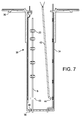
On a illustré sur la figure 7 l'application
des pontets de l'invention au cheminement de
conducteurs électriques de mesure, simplement appelés
"mesures" en terme de métier, dans une canne
d'instrumentation qui peut être appliquée, par exemple
à la mesure de paramètres de fonctionnement d'un moteur
d'avion. La canne d'instrumentation, désignée dans son
ensemble par la référence générale 32, se compose d'un
cylindre 34 allongé disposé verticalement et d'un
flasque de fixation 36 situé à une extrémité ouverte du
cylindre 34. Le fond 38 du cylindre 34 comporte un ou
plusieurs trous 40 pour le passage des mesures 8. Les
mesures 8 sont destinées à être raccordées à des
parties non représentées du moteur auquel la canne est
destinée. Les mesures 8 sont maintenues sur la paroi
intérieure du cylindre 34, réalisé en acier, par une
série de pontets 20 soudés électriquement. Le diamètre
du cylindre 34 étant trop petit pour que l'on puisse
introduire les mains, les pontets sont déplacés au
moyen d'une électrode 42 d'un poste de soudure
électrique. A cet effet, on dispose un élément d'arrêt
43, par exemple un morceau de ruban adhésif, sur le
faisceau des mesures 8 puis on enfile les pontets 20
l'un après l'autre sur le faisceau des mesures à la
manière de perles. On dispose l'ensemble à l'intérieur
de la canne, l'élément d'arrêt 43 étant placé vers le
bas à proximité du fond 38. On vient ensuite chercher
le pontet situé immédiatement au-dessus de l'élément
d'arrêt à l'aide de la pointe 44 de l'électrode 42 et
on le remonte en prenant appui sur l'un des rebord 30
prévu sur les ailes 26(figure 4) jusqu'à la position à
laquelle il doit être fixé et on le soude dans cette
position. On effectue ensuite la même opération avec le
pontet situé immédiatement au-dessus du premier pontet
et ainsi de suite jusqu'à avoir fixer l'ensemble des
pontets régulièrement espacés des uns des autres.FIG. 7 illustrates the application
bridges of the invention to the path of
electrical measuring leads, simply called
"measures" in terms of trade, in a cane
instrumentation that can be applied, for example
to the measurement of operating parameters of an engine
airline. The instrumentation rod, designated in its
together by the
Le pontet qui vient d'être décrit permet un
gain de temps et une meilleure qualité du cheminement
des mesures 8. Une partie du travail s'effectuant avant
le cheminement à l'intérieur de la canne le cycle
global d'instrumentation est raccourci. Il est possible
de faire varier le diamètre des pontets en fonction du
nombre de mesures 8 et des diamètres utilisés pour le
cheminement. On peut aussi faire coulisser les mesures
8 lors du démontage en laissant les pontets en place ce
qui évite leur détérioration.The bridge which has just been described allows a
save time and improve the quality of the
Claims (9)
caractérisé en ce que la partie de maintien (24, 28) présente une section circulaire.Bridge according to claim 1,
characterized in that the holding portion (24, 28) has a circular section.
Applications Claiming Priority (2)
| Application Number | Priority Date | Filing Date | Title |
|---|---|---|---|
| FR0451036A FR2870915A1 (en) | 2004-05-26 | 2004-05-26 | IMPERFITABLE PONTET AND METHOD FOR IMPLEMENTING SAID PONTET |
| FR0451036 | 2004-05-26 |
Publications (2)
| Publication Number | Publication Date |
|---|---|
| EP1601076A2 true EP1601076A2 (en) | 2005-11-30 |
| EP1601076A3 EP1601076A3 (en) | 2006-02-15 |
Family
ID=34946758
Family Applications (1)
| Application Number | Title | Priority Date | Filing Date |
|---|---|---|---|
| EP05104399A Withdrawn EP1601076A3 (en) | 2004-05-26 | 2005-05-24 | Non-losable bridge and implementation of the same |
Country Status (5)
| Country | Link |
|---|---|
| US (1) | US20050263651A1 (en) |
| EP (1) | EP1601076A3 (en) |
| CA (1) | CA2508334A1 (en) |
| FR (1) | FR2870915A1 (en) |
| RU (1) | RU2005115952A (en) |
Cited By (1)
| Publication number | Priority date | Publication date | Assignee | Title |
|---|---|---|---|---|
| FR2966651A1 (en) * | 2010-10-21 | 2012-04-27 | Snecma | DEVICE FOR DETECTING ELECTRIC HARNESSES IN A TURBOMACHINE |
Families Citing this family (5)
| Publication number | Priority date | Publication date | Assignee | Title |
|---|---|---|---|---|
| CA2478727C (en) * | 2003-08-26 | 2013-03-05 | Virgil E. O'neil | Embedded pipe hanger |
| US7770851B2 (en) * | 2006-12-21 | 2010-08-10 | Thomas & Betts International, Inc. | Retaining element including enhanced engagement features |
| US9677691B2 (en) | 2013-04-29 | 2017-06-13 | The Reliable Automatic Sprinkler Company | Sprinkler fitting bracket |
| USD742213S1 (en) * | 2014-01-30 | 2015-11-03 | Tallmadge Spinning & Metal Company | Pipe clamp bracket |
| GB2521504B (en) * | 2014-10-02 | 2015-11-11 | Strip Fix Ltd | An attachment means |
Citations (6)
| Publication number | Priority date | Publication date | Assignee | Title |
|---|---|---|---|---|
| DE1961152U (en) * | 1967-02-15 | 1967-06-01 | Jan M Chrzescinski | CLAMP CABLE. |
| US4300284A (en) * | 1978-12-15 | 1981-11-17 | Raychem Corporation | Method and apparatus to organize and to electrically connect wires |
| CH689793A5 (en) * | 1995-03-01 | 1999-11-15 | Sts Gmbh | Cable or pipe clamp strip for clamping cables or pipes such as hot and cold water pipes eliminates material loss and saves time during installation and designed to have no sharp edges |
| US6010099A (en) * | 1997-12-17 | 2000-01-04 | The Whitaker Corporation | Dimple forming clamp used to hold spring jacketed cable |
| EP1010928A2 (en) * | 1998-12-18 | 2000-06-21 | General Electric Company | Robust tube strap clamp |
| US6274815B1 (en) * | 1998-06-05 | 2001-08-14 | Yazaki Corporation | Circuit member-holding clamp and method of producing same |
Family Cites Families (21)
| Publication number | Priority date | Publication date | Assignee | Title |
|---|---|---|---|---|
| US325767A (en) * | 1885-09-08 | Thomas w | ||
| US566544A (en) * | 1896-08-25 | Plumber s tack | ||
| US938216A (en) * | 1908-07-31 | 1909-10-26 | Frank B Cook | Messenger-hanger. |
| US1529881A (en) * | 1922-08-25 | 1925-03-17 | Ray S Engle | Combined staple and strap |
| US1818625A (en) * | 1925-04-13 | 1931-08-11 | Gen Cable Corp | Conduit securing means |
| US1736807A (en) * | 1927-04-25 | 1929-11-26 | Clifford S Thomas | Cable clamp |
| US2003159A (en) * | 1933-04-05 | 1935-05-28 | Lamson Co | Pneumatic dispatch system |
| US2394240A (en) * | 1941-12-20 | 1946-02-05 | Bendix Aviat Corp | Gang clamp |
| US3263947A (en) * | 1964-03-20 | 1966-08-02 | Kerttunen Tuomas | Clamp for conductors or the like |
| US3273839A (en) * | 1964-07-30 | 1966-09-20 | Tinnerman Products Inc | Fastening devices |
| US3357664A (en) * | 1965-10-14 | 1967-12-12 | Gen Electric | Tube supports |
| US3292886A (en) * | 1966-02-18 | 1966-12-20 | Robert S Rovinsky | Bracket |
| US4093761A (en) * | 1972-03-08 | 1978-06-06 | Taylor Industries, Inc. | Sheet with breakaway line |
| US5297890A (en) * | 1992-02-20 | 1994-03-29 | Simpson Strong-Tie Company, Inc. | Wood-to-pipe connection |
| USD394997S (en) * | 1996-11-07 | 1998-06-09 | Diamond Communication Products, Inc. | Ganged cable clip |
| US5806813A (en) * | 1997-01-06 | 1998-09-15 | Lab Holding Company | Tubing bracket assembly |
| US5839703A (en) * | 1997-02-27 | 1998-11-24 | Perfection Corporation | Anti-rotation bracket |
| US20030029972A1 (en) * | 2001-08-08 | 2003-02-13 | Rodgers J. Linn | Stabilizer for objects such as cables and wires |
| WO2003056673A1 (en) * | 2001-12-21 | 2003-07-10 | Ccs Technology, Inc. | Method for introducing an assembly for housing at least one optical conductor into a road and a cable laying device comprising a cable assembly that contains an optical conductor |
| DE10253996A1 (en) * | 2002-11-19 | 2004-06-03 | Hilti Ag | Holding element for cable strands, such as pipes, cable strands or cable guides |
| US7071410B1 (en) * | 2005-04-06 | 2006-07-04 | Bridgeport Fittings, Inc. | Protective shield for utility supplying tubes, cables and conduits |
-
2004
- 2004-05-26 FR FR0451036A patent/FR2870915A1/en not_active Withdrawn
-
2005
- 2005-05-24 EP EP05104399A patent/EP1601076A3/en not_active Withdrawn
- 2005-05-25 CA CA002508334A patent/CA2508334A1/en not_active Abandoned
- 2005-05-25 RU RU2005115952/11A patent/RU2005115952A/en not_active Application Discontinuation
- 2005-05-25 US US11/136,373 patent/US20050263651A1/en not_active Abandoned
Patent Citations (6)
| Publication number | Priority date | Publication date | Assignee | Title |
|---|---|---|---|---|
| DE1961152U (en) * | 1967-02-15 | 1967-06-01 | Jan M Chrzescinski | CLAMP CABLE. |
| US4300284A (en) * | 1978-12-15 | 1981-11-17 | Raychem Corporation | Method and apparatus to organize and to electrically connect wires |
| CH689793A5 (en) * | 1995-03-01 | 1999-11-15 | Sts Gmbh | Cable or pipe clamp strip for clamping cables or pipes such as hot and cold water pipes eliminates material loss and saves time during installation and designed to have no sharp edges |
| US6010099A (en) * | 1997-12-17 | 2000-01-04 | The Whitaker Corporation | Dimple forming clamp used to hold spring jacketed cable |
| US6274815B1 (en) * | 1998-06-05 | 2001-08-14 | Yazaki Corporation | Circuit member-holding clamp and method of producing same |
| EP1010928A2 (en) * | 1998-12-18 | 2000-06-21 | General Electric Company | Robust tube strap clamp |
Cited By (1)
| Publication number | Priority date | Publication date | Assignee | Title |
|---|---|---|---|---|
| FR2966651A1 (en) * | 2010-10-21 | 2012-04-27 | Snecma | DEVICE FOR DETECTING ELECTRIC HARNESSES IN A TURBOMACHINE |
Also Published As
| Publication number | Publication date |
|---|---|
| CA2508334A1 (en) | 2005-11-26 |
| RU2005115952A (en) | 2006-11-27 |
| US20050263651A1 (en) | 2005-12-01 |
| FR2870915A1 (en) | 2005-12-02 |
| EP1601076A3 (en) | 2006-02-15 |
Similar Documents
| Publication | Publication Date | Title |
|---|---|---|
| EP1601076A2 (en) | Non-losable bridge and implementation of the same | |
| EP2115837B1 (en) | Attachment device for a yarn cable track | |
| CH699811B1 (en) | Bracelet with articulated links and a method of assembling such a bracelet | |
| FR2864461A1 (en) | HAND TUBE OF A WORK TOOL GUIDE AND MANEUVER BY HAND | |
| FR2791115A1 (en) | FIXING ELEMENT FOR A MESH GUTTER | |
| FR2737739A1 (en) | MOBILE CROSSING HEAD POINT FOR LARGE LENGTH FERROUS TRACKING DEVICES INCORPORATED IN LONG WELDED RAILS | |
| FR3004067A1 (en) | PROFILE, IN PARTICULAR METALLIC, FOR ALLOWING A FIXATION OF A FILM ON A GREENHOUSE STRUCTURE AND A SYSTEM FOR FIXING A FILM ON A GREENHOUSE STRUCTURE COMPRISING SUCH A PROFILE | |
| FR2746148A1 (en) | COMPOSITE PIECE | |
| EP1086323B1 (en) | Screwed conveyor belt fastener | |
| CA2708972C (en) | Blocking ring for osteosynthesis device and osteosynhesis device including such ring | |
| FR2762144A1 (en) | DIRECT DARK EARTHING POLE, MANUFACTURING METHOD THEREOF, AND SELF-LOCKING TERMINAL FOR PARTICULARLY CONNECTING THIS POLE TO AN ELECTRICAL CONDUCTOR | |
| FR2716768A1 (en) | Mounting element for mounting accessory such as cableway on wall | |
| WO2009133250A1 (en) | Anchor clamp for telecommunications cable | |
| FR2613550A1 (en) | Device for fixing a plurality of cables to a support | |
| BE1015509A3 (en) | Tree-dozer head for cutting grass, has wires extending over peripheral wall that includes perforations forming channels, and fixation applied to part of wires such that fixation is disposed within cavity of channels | |
| CH558639A (en) | Link type watch bracelet - links held together by internal threaded plastics tendons | |
| FR2580892A1 (en) | METHOD OF FIXING A CONNECTOR ON THE SUBSTRATE OF A PIONEER PRINTED CIRCUIT FOR ATTACHING THE CONNECTOR TO THE SUBSTRATE | |
| FR2886355A1 (en) | Component fixing system comprises anchoring element that can be attached to first component before it is joined to second one | |
| FR3113229A1 (en) | Wall mounting assembly having hooks, and corresponding complementary member | |
| CH282161A (en) | Apparatus for maintaining end to end at least two profiled elements, of elongated shape, with a view to their assembly. | |
| FR2720382A1 (en) | Elevator car support bar | |
| FR2723265A1 (en) | Electrical terminal box for cables of differing cross=section | |
| FR2869728A1 (en) | Wire connection device, has guiding assembly with guide tracks forming support for washer and terminal lug of wire, and having aligning portion centered on axis of tapped hole to receive lug and/or washer and rod of screw | |
| FR3123083A1 (en) | BARRED GRID ELEMENT AND CORRESPONDING FENCE | |
| FR2926448A1 (en) | Polygonal decorative element e.g. rectangular canvas, suspending arrangement for use on e.g. vertical wall, has single wire or cable with ends connected to sidewall and received in guides around frame for suspending decorative element |
Legal Events
| Date | Code | Title | Description |
|---|---|---|---|
| PUAI | Public reference made under article 153(3) epc to a published international application that has entered the european phase |
Free format text: ORIGINAL CODE: 0009012 |
|
| AK | Designated contracting states |
Kind code of ref document: A2 Designated state(s): AT BE BG CH CY CZ DE DK EE ES FI FR GB GR HU IE IS IT LI LT LU MC NL PL PT RO SE SI SK TR |
|
| AX | Request for extension of the european patent |
Extension state: AL BA HR LV MK YU |
|
| PUAL | Search report despatched |
Free format text: ORIGINAL CODE: 0009013 |
|
| AK | Designated contracting states |
Kind code of ref document: A3 Designated state(s): AT BE BG CH CY CZ DE DK EE ES FI FR GB GR HU IE IS IT LI LT LU MC NL PL PT RO SE SI SK TR |
|
| AX | Request for extension of the european patent |
Extension state: AL BA HR LV MK YU |
|
| AKX | Designation fees paid | ||
| REG | Reference to a national code |
Ref country code: DE Ref legal event code: 8566 |
|
| STAA | Information on the status of an ep patent application or granted ep patent |
Free format text: STATUS: THE APPLICATION IS DEEMED TO BE WITHDRAWN |
|
| 18D | Application deemed to be withdrawn |
Effective date: 20060817 |