EP1601045A2 - Foldable portable telephone using one of the shieldings as a second antenna - Google Patents
Foldable portable telephone using one of the shieldings as a second antenna Download PDFInfo
- Publication number
- EP1601045A2 EP1601045A2 EP05018534A EP05018534A EP1601045A2 EP 1601045 A2 EP1601045 A2 EP 1601045A2 EP 05018534 A EP05018534 A EP 05018534A EP 05018534 A EP05018534 A EP 05018534A EP 1601045 A2 EP1601045 A2 EP 1601045A2
- Authority
- EP
- European Patent Office
- Prior art keywords
- antenna
- casing
- portable telephone
- circuit
- shield member
- Prior art date
- Legal status (The legal status is an assumption and is not a legal conclusion. Google has not performed a legal analysis and makes no representation as to the accuracy of the status listed.)
- Withdrawn
Links
Images



Classifications
-
- H—ELECTRICITY
- H01—ELECTRIC ELEMENTS
- H01Q—ANTENNAS, i.e. RADIO AERIALS
- H01Q21/00—Antenna arrays or systems
- H01Q21/28—Combinations of substantially independent non-interacting antenna units or systems
-
- H—ELECTRICITY
- H01—ELECTRIC ELEMENTS
- H01Q—ANTENNAS, i.e. RADIO AERIALS
- H01Q1/00—Details of, or arrangements associated with, antennas
- H01Q1/08—Means for collapsing antennas or parts thereof
- H01Q1/084—Pivotable antennas
-
- H—ELECTRICITY
- H01—ELECTRIC ELEMENTS
- H01Q—ANTENNAS, i.e. RADIO AERIALS
- H01Q1/00—Details of, or arrangements associated with, antennas
- H01Q1/12—Supports; Mounting means
- H01Q1/22—Supports; Mounting means by structural association with other equipment or articles
- H01Q1/24—Supports; Mounting means by structural association with other equipment or articles with receiving set
- H01Q1/241—Supports; Mounting means by structural association with other equipment or articles with receiving set used in mobile communications, e.g. GSM
- H01Q1/242—Supports; Mounting means by structural association with other equipment or articles with receiving set used in mobile communications, e.g. GSM specially adapted for hand-held use
- H01Q1/243—Supports; Mounting means by structural association with other equipment or articles with receiving set used in mobile communications, e.g. GSM specially adapted for hand-held use with built-in antennas
-
- H—ELECTRICITY
- H01—ELECTRIC ELEMENTS
- H01Q—ANTENNAS, i.e. RADIO AERIALS
- H01Q1/00—Details of, or arrangements associated with, antennas
- H01Q1/12—Supports; Mounting means
- H01Q1/22—Supports; Mounting means by structural association with other equipment or articles
- H01Q1/24—Supports; Mounting means by structural association with other equipment or articles with receiving set
- H01Q1/241—Supports; Mounting means by structural association with other equipment or articles with receiving set used in mobile communications, e.g. GSM
- H01Q1/242—Supports; Mounting means by structural association with other equipment or articles with receiving set used in mobile communications, e.g. GSM specially adapted for hand-held use
- H01Q1/245—Supports; Mounting means by structural association with other equipment or articles with receiving set used in mobile communications, e.g. GSM specially adapted for hand-held use with means for shaping the antenna pattern, e.g. in order to protect user against rf exposure
-
- H—ELECTRICITY
- H04—ELECTRIC COMMUNICATION TECHNIQUE
- H04B—TRANSMISSION
- H04B1/00—Details of transmission systems, not covered by a single one of groups H04B3/00 - H04B13/00; Details of transmission systems not characterised by the medium used for transmission
- H04B1/38—Transceivers, i.e. devices in which transmitter and receiver form a structural unit and in which at least one part is used for functions of transmitting and receiving
- H04B1/3827—Portable transceivers
- H04B1/3833—Hand-held transceivers
-
- H—ELECTRICITY
- H04—ELECTRIC COMMUNICATION TECHNIQUE
- H04B—TRANSMISSION
- H04B1/00—Details of transmission systems, not covered by a single one of groups H04B3/00 - H04B13/00; Details of transmission systems not characterised by the medium used for transmission
- H04B1/38—Transceivers, i.e. devices in which transmitter and receiver form a structural unit and in which at least one part is used for functions of transmitting and receiving
- H04B1/3827—Portable transceivers
- H04B1/3833—Hand-held transceivers
- H04B1/3838—Arrangements for reducing RF exposure to the user, e.g. by changing the shape of the transceiver while in use
-
- H—ELECTRICITY
- H04—ELECTRIC COMMUNICATION TECHNIQUE
- H04B—TRANSMISSION
- H04B15/00—Suppression or limitation of noise or interference
- H04B15/02—Reducing interference from electric apparatus by means located at or near the interfering apparatus
-
- H—ELECTRICITY
- H04—ELECTRIC COMMUNICATION TECHNIQUE
- H04M—TELEPHONIC COMMUNICATION
- H04M1/00—Substation equipment, e.g. for use by subscribers
- H04M1/02—Constructional features of telephone sets
- H04M1/0202—Portable telephone sets, e.g. cordless phones, mobile phones or bar type handsets
- H04M1/0206—Portable telephones comprising a plurality of mechanically joined movable body parts, e.g. hinged housings
- H04M1/0208—Portable telephones comprising a plurality of mechanically joined movable body parts, e.g. hinged housings characterized by the relative motions of the body parts
- H04M1/0214—Foldable telephones, i.e. with body parts pivoting to an open position around an axis parallel to the plane they define in closed position
Definitions
- the present invention relates to portable telephones, and more particularly, to a portable telephone having first and second casings coupled to each other via a hinge portion and foldable about the hinge portion.
- Fig. 14 is a perspective view showing a structure of a conventional portable telephone 31.
- portable telephone 31 is provided with an upper casing 33 and a lower casing 34 that are coupled with each other via a hinge portion 32, and is foldable about hinge portion 32.
- a receiver 35 and a liquid crystal panel 36 are provided on the surface of upper casing 33.
- a transmitter 37 and a keypad 38 are provided on the surface of lower casing 34.
- Upper casing 33 and lower casing 34 are connected to each other via a flexible cable 39.
- a retractable rod antenna 40 is provided at an upper end of lower casing 34. Rod antenna 40 is used for transmitting signals to and receiving signals from a base station.
- a user of portable telephone 31 holds lower casing 34 in his/her hand, and talks on the phone bringing receiver 35 close to his/her ear.
- portable telephone 31 is folded and put away, e.g., in a pocket of the user's garment.
- a main object of the present invention is to provide a portable telephone that suffers less variation in gain dependent on a state of the user's hand.
- the portable telephone includes: first and second electronic circuit portions provided within first and second casings, respectively; and first and second shield members for shielding the first and second electronic circuit portions, respectively. At least one of the first and second shield members additionally serves as an antenna of the portable telephone. Since the shield member used as the antenna is considerably larger than a conventional antenna, variation in gain dependent on a state of the user's hand holding the portable telephone can be alleviated, so that a stable communication condition is realized.
- the first electronic circuit portion includes a communication circuit for communicating with a base station using the second shield member as the antenna.
- the variation in gain dependent on a state of the user's hand can further be lessened.
- the second shield member includes a slit for adjusting its characteristics as the antenna.
- the characteristics of the second shield member as the antenna can be optimized.
- the second shield member includes an extended portion for adjusting its characteristics as the antenna.
- the characteristics as the antenna of the second shield member can be optimized.
- the portable telephone above is further provided with an antenna matching circuit that is connected between the communication circuit and the second shield member.
- an antenna matching circuit that is connected between the communication circuit and the second shield member.
- the portable telephone above is further provided with: a first antenna matching circuit for matching when the portable telephone is unfolded; a second antenna matching circuit for matching when the portable telephone is folded; a detector for detecting whether the portable telephone is folded; and a switching circuit operating based on the detected result of the detector, to connect the first antenna matching circuit between the communication circuit and the second shield member when the portable telephone is unfolded, and to connect the second antenna matching circuit between the communication circuit and the second shield member when the portable telephone is folded.
- a first antenna matching circuit for matching when the portable telephone is unfolded
- a second antenna matching circuit for matching when the portable telephone is folded
- a detector for detecting whether the portable telephone is folded
- a switching circuit operating based on the detected result of the detector, to connect the first antenna matching circuit between the communication circuit and the second shield member when the portable telephone is unfolded, and to connect the second antenna matching circuit between the communication circuit and the second shield member when the portable telephone is folded.
- the portable telephone above is further provided with an antenna that is mounted to the first casing and has its feeding portion connected to the communication circuit.
- the communication circuit communicates with the base station via the second shield member and the antenna.
- the portable telephone above is further provided with an antenna that is mounted to the second casing and has its feeding portion connected to the second shield member.
- the communication circuit communicates with the base station via the second shield member and the antenna.
- the portable telephone above is further provided with an antenna matching circuit that is connected between the second shield member and the feeding portion of the antenna. In this case, efficient signal transmission/reception is enabled.
- the portable telephone above is further provided with: an antenna that is mounted to the first casing; a detector for detecting whether a hand of a user of the portable telephone is touching the antenna; and a switching circuit operating based on the detected result of the detector, to connect the communication circuit to the antenna when the user's hand is not touching the antenna, and to connect the communication circuit to the second shield member when the user's hand is touching the antenna.
- the communication circuit communicates with the base station via the antenna or the second shield member that is connected thereto by the switching circuit. In this case, a good communication condition is ensured regardless of whether or not the user's hand is touching the antenna.
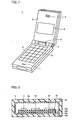
- Fig. 1 is a perspective view showing a structure of the portable telephone 1 according to an embodiment of the present invention.
- portable telephone 1 includes an upper casing 3 and a lower casing 4 connected to each other via a hinge portion 2, and is foldable about hinge portion 2.
- a receiver 5 and a liquid crystal panel 6 are provided on a surface of upper casing 3.
- a transmitter 7 and a keypad 8 are provided on a surface of lower casing 4.
- a flexible cable 9 connects upper casing 3 and lower casing 4.
- a shield box 14 which will be described later. This shield box 14 additionally serves as an antenna for transmitting and receiving signals to and from a base station.
- a user of portable telephone 1 holds the lower casing in his/her hand, and talks on the phone with his/her ear close to receiver 5.
- portable telephone 1 is folded and put away, e.g., in a pocket of the user's garment.
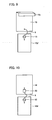
- Fig. 2 is a cross sectional view showing upper casing 3 and an inner structure thereof. Referring to Fig. 2, at least the surfaces of upper casing 3 are formed of an insulator, and a shield layer 3a formed of a conductive member covers the inner walls thereof.
- a multilayer substrate 10 is accommodated in upper casing 3, and various kinds of electronic components 11-13, ... constituting a liquid crystal display and others are mounted on the surface of multilayer substrate 10.
- Multilayer substrate 10 is formed of a plurality of conductive layers and a plurality of insulating layers stacked alternately one on another.
- the respective conductive layers are used for a power supply layer, a ground layer, a signal interconnection layer and others.
- a ground layer 10b for electronic components 11-13, ..., a ground layer 10d for shielding, an insulating layer 10a provided between electronic components 11-13, ... and ground layer 10b, and an insulating layer 10c interposed between ground layers 10b and 10d are illustrated in Fig. 2.
- Ground layer 10d and shield layer 3a, conducting to each other, constitute the shield box 14.
- Shield box 14 protects electronic components 11-13, ... from external noise, prevents noise generated in electronic components 11-13, ... from leaking outward, and additionally works as an antenna.
- Lower casing 4 and its interior have structures basically identical to those of upper casing 3 and its interior. More specifically, as shown in Fig. 3, lower casing 4 includes a multilayer substrate 10' and a shield box 14' for shielding the substrate. Multilayer substrate 10' and shield box 14' have the same structures as multilayer substrate 10 and shield box 14 shown in Fig. 2. A plurality of electronic components constituting a transmitting circuit 15, a receiving circuit and others are mounted on the surface of multilayer substrate 10'. Multilayer substrate 10 within upper casing 3 and multilayer substrate 10' within lower casing 4 are connected to each other via a flexible cable 9.
- ground layers 10b and 10b' for electronic components conduct to each other, and ground layers 10d and 10d' for shielding also conduct to each other.
- Ground layers 10b, 10b' for electronic components and ground layers 10d, 10d' for shielding are insulated from each other.
- a ground terminal of transmitting circuit 15 is connected to ground layer 10b' of multilayer substrate 10', and an output terminal of transmitting circuit 15 is connected via flexible cable 9 to ground layer 10d of multilayer substrate 10 or to shield box 14.
- the outer sheath of shield box 14 is used as the antenna. Since the shield box 14 is considerably larger than the conventional rod antenna 40, variation in gain dependent on a state of the user's hand holding portable telephone 1 is lessened than in the conventional case, so that stable signal transmission/reception is enabled.
- a rod antenna 16 is further provided to the embodiment shown in Fig. 4.
- Rod antenna 16 is mounted to lower casing 4, and its base end (a feeding portion) is connected to the output terminal of transmitting circuit 15.
- rod antenna 16 is used in addition to shield box 14 serving as the antenna, and thus, high gain is obtained. Accordingly, the variation in gain dependent on a state of the user's hand holding portable telephone 1 is further lessened than in the conventional case.
- rod antenna 16 is further provided to the embodiment of Fig. 4.
- rod antenna 16 is mounted to upper casing 3, and its base end is connected to an upper end of shield box 14.
- shield box 14 is used as the antenna and also as a power transmission line, and rod antenna 16 is also utilized. Accordingly, high gain is obtained, and the variation in gain dependent on a state of the user's hand is alleviated.
- transmitting circuit 15 and others are provided on the upper casing 3 side, while liquid crystal panel 6 and others are provided on the lower casing 4 side. It is configured such that the user holds upper casing 3 when talking on the phone.
- the ground terminal of transmitting circuit 15 is connected to ground layer 10b of multilayer substrate 10, and the output terminal of transmitting circuit 15 is connected via flexible cable 9 to shield box 14'. In this case, again, the variation in gain dependent on a state of the user's hand is alleviated.
- shield box 14 of the embodiment of Fig. 4 is replaced with a shield box 17.
- Shield box 17 is provided with a slit 17a to cause the antenna current to detour. By adjusting the shape and dimensions of slit 17a, it is possible to optimize the characteristics of shield box 17 as an antenna.
- shield box 17 of the variation in Fig. 8 is replaced with a shield box 18.
- Shield box 18 is provided with a fin 18a at its end portion for adjustment of a length of the current path. Adjusting the shape and dimensions of fin 18a enables the characteristics of shield box 18 as an antenna to be optimized.
- a matching circuit 20 is interposed between flexible cable 9 and shield box 14 of the embodiment shown in Fig. 4. In this case, it is possible to minimize a reflection level and input impedance of a signal in shield box 14, and thus, efficient signal transmission/reception is enabled.
- matching circuit 20 may be interposed between the output terminal of transmitting circuit 15 and flexible cable 9.
- a matching circuit 21 is interposed between the base end of rod antenna 16 and shield box 14 of the variation shown in Fig. 6. In this case, a reflection level and input impedance of a signal in rod antenna 16 can be minimized, so that efficient signal transmission/reception is enabled.
- Matching circuit 21 may be interposed between flexible cable 9 and shield box 14, or between flexible cable 9 and the output terminal of transmitting circuit 15.
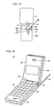
- the variation shown in Fig. 12 is the case where a matching circuit 22, a switch 23 and a sensor 24 are added to the variation shown in Fig. 10.
- Switch 23 has an output terminal 23c that is connected via flexible cable 9 to the output terminal of transmitting circuit 15, one switching terminal 23a that is connected via matching circuit 20 to shield box 14, and the other switching terminal 23b that is connected via matching circuit 22 to shield box 14.
- Matching circuit 20 is configured to minimize a reflection level and input impedance of a signal in shield box 14 in the state where the portable telephone is unfolded.
- Matching circuit 22 is configured to minimize the reflection level and input impedance of the signal in shield box 14 in the state where the portable telephone is folded.
- Sensor 24 detects whether the portable telephone is folded, and outputs a signal of an H level when it is unfolded, and outputs a signal of an L level when it is folded.
- the signal of an L level output from sensor 24 causes terminals 23c and 23b of switch 23 to conduct.
- the output terminal of transmitting circuit 15 is connected via flexible cable 9, switch 23 and matching circuit 22 to shield box 14. Accordingly, regardless of whether the portable telephone is folded or not, the input impedance and reflection level of the signal in shield box 14 can be minimized, and thus, efficient signal transmission/reception is enabled.
- Switch 25 has a common terminal 25c connected to the output terminal of transmitting circuit 15, one switching terminal 25a connected to the base end of rod antenna 16, and the other switching terminal 25b connected via flexible cable 9 to shield box 14.
- Sensor 26 detects whether the user's hand is touching rod antenna 16. When the hand is not touching the antenna, sensor 26 outputs a signal of an H level. If the hand is touching the antenna, it outputs a signal of an L level.
Landscapes
- Engineering & Computer Science (AREA)
- Computer Networks & Wireless Communication (AREA)
- Signal Processing (AREA)
- Telephone Set Structure (AREA)
- Support Of Aerials (AREA)
- Transceivers (AREA)
- Details Of Aerials (AREA)
- Mobile Radio Communication Systems (AREA)
Abstract
Description
Claims (10)
- A portable telephone, comprising:a first electronic circuit portion (15);a second electronic circuit portion (11 - 13);a substrate (10) including a ground layer (10d) and having the second electronic circuit portion (11 - 13) mounted thereon;a shield member (14) including a shield layer (3a), the shield layer (3a) being formed of a conductive member, shielding the second electronic circuit portion (11 - 13) on the substrate (10), and in electrical conduction with the ground layer (10d) of the substrate (10);a communication circuit (15) constituting an electronic part included in the first electronic circuit portion and electrically connected to the ground layer (10d); anda conduction member (9) electrically connecting the communication circuit (15) to the ground layer (10d).
- The portable telephone according to claim 1, further comprising:a first casing (4) provided with an operating portion (8) and accommodating the first electronic circuit portion (15) therein;a second casing (3) provided with a display portion (6) and accommodating the substrate (10) therein; andan antenna (16) mounted to one of the first casing (4) and the second casing (3);the communication circuit (15) being electrically connected to the antenna (16) and the ground layer (10d) of the substrate (10).
- The portable telephone according to claim 1 or 2,
wherein the shield member (17) includes a slit (17a) for adjusting its characteristics as an antenna. - The portable telephone according to claim 1 or 2,
wherein the shield member (18) includes an extended portion (18a) for adjusting its characteristics as an antenna. - The portable telephone according to claim 1 or 2,
further comprising an antenna matching circuit (20) connected between the communication circuit (15) and the shield member (14). - The portable telephone according to claim 2,
wherein the first casing (4) and the second casing (3) are coupled to each other in a foldable manner via a hinge portion (2),
and wherein the portable telephone further comprises:a first antenna matching circuit (20) for matching when the first casing (4) and the second casing (3) are unfolded;a second antenna matching circuit (22) for matching when the first casing (4) and the second casing (3) are folded;a detector (24) for detecting whether the first casing (4) and the second casing (3) are folded; anda switching circuit (23) adapted to operate based on a detected result of the detector (24), for connecting the first antenna matching circuit (20) between the communication circuit (15) and the shield member (14) when the first casing (4) and the second casing (3) are unfolded, and for connecting the second antenna matching circuit (22) between the communication circuit (15) and the shield member (14) when the first casing (4) and the second casing (3) are folded. - The portable telephone according to claim 2,
wherein the antenna (16) is mounted to the first casing (4) and has its feeding portion connected to the communication circuit (15), and
wherein the communication circuit (15) is adapted to communicate with a base station via the shield member (14) and the antenna (16). - The portable telephone according to claim 2,
wherein the antenna (16) is mounted to the second casing (3) and has its feeding portion connected to the shield member (14), and
wherein the communication circuit (15) is adapted to communicate with a base station via the shield member (14) and the antenna (16). - The portable telephone according to claim 8,
further comprising a matching circuit (21) for the antenna (16) that is connected between the shield member (14) and the feeding portion of the antenna (16). - The portable telephone according to claim 2,
wherein the antenna (16) is mounted to the first casing (4), and wherein the portable telephone further comprises:a detector (26) for detecting whether a hand of a user of the portable telephone is touching the antenna (16); anda switching circuit (25) adapted to operate based on a detected result of the detector (26), for connecting the communication circuit (15) to the antenna (16) when the user's hand is not touching the antenna (16), and for connecting the communication circuit (15) to the shield member (14) when the user's hand is touching the antenna (16),the communication circuit (15) being adapted to communicate with a base station via either one of the antenna (16) and the shield member (14) that is connected to the communication circuit (15) by the switching circuit (25).
Applications Claiming Priority (3)
| Application Number | Priority Date | Filing Date | Title |
|---|---|---|---|
| JP2001137740 | 2001-05-08 | ||
| JP2001137740A JP3830773B2 (en) | 2001-05-08 | 2001-05-08 | Mobile phone |
| EP02008497A EP1258943A1 (en) | 2001-05-08 | 2002-04-15 | Foldable portable telephone using one of the shieldings as a second antenna |
Related Parent Applications (2)
| Application Number | Title | Priority Date | Filing Date |
|---|---|---|---|
| EP02008497.6 Division | 2002-04-15 | ||
| EP02008497A Division EP1258943A1 (en) | 2001-05-08 | 2002-04-15 | Foldable portable telephone using one of the shieldings as a second antenna |
Publications (2)
| Publication Number | Publication Date |
|---|---|
| EP1601045A2 true EP1601045A2 (en) | 2005-11-30 |
| EP1601045A3 EP1601045A3 (en) | 2011-05-04 |
Family
ID=18984799
Family Applications (2)
| Application Number | Title | Priority Date | Filing Date |
|---|---|---|---|
| EP02008497A Withdrawn EP1258943A1 (en) | 2001-05-08 | 2002-04-15 | Foldable portable telephone using one of the shieldings as a second antenna |
| EP05018534A Withdrawn EP1601045A3 (en) | 2001-05-08 | 2002-04-15 | Foldable portable telephone using one of the shieldings as a second antenna |
Family Applications Before (1)
| Application Number | Title | Priority Date | Filing Date |
|---|---|---|---|
| EP02008497A Withdrawn EP1258943A1 (en) | 2001-05-08 | 2002-04-15 | Foldable portable telephone using one of the shieldings as a second antenna |
Country Status (4)
| Country | Link |
|---|---|
| US (1) | US7079877B2 (en) |
| EP (2) | EP1258943A1 (en) |
| JP (1) | JP3830773B2 (en) |
| CN (1) | CN1252939C (en) |
Cited By (1)
| Publication number | Priority date | Publication date | Assignee | Title |
|---|---|---|---|---|
| GB2424996A (en) * | 2005-02-25 | 2006-10-11 | Kyocera Corp | Folding wireless device with a signal line and a conductive reference layer arrangement |
Families Citing this family (85)
| Publication number | Priority date | Publication date | Assignee | Title |
|---|---|---|---|---|
| EP1306922A3 (en) * | 2001-10-24 | 2006-08-16 | Matsushita Electric Industrial Co., Ltd. | Antenna structure, methof of using antenna structure and communication device |
| JP2003304111A (en) * | 2002-04-09 | 2003-10-24 | Nec Corp | Antenna |
| JP4096294B2 (en) * | 2002-05-14 | 2008-06-04 | 日本電気株式会社 | Mobile phone equipment |
| US8060167B2 (en) | 2002-07-19 | 2011-11-15 | Panasonic Corporation | Portable wireless machine |
| JP3613527B2 (en) * | 2003-06-12 | 2005-01-26 | 松下電器産業株式会社 | Portable radio |
| EP1538694B1 (en) * | 2002-07-19 | 2010-04-14 | Panasonic Corporation | Portable wireless machine |
| USD476303S1 (en) | 2002-08-08 | 2003-06-24 | Appeal Telecom Co., Ltd. | Cellular phone |
| USD475987S1 (en) | 2002-08-08 | 2003-06-17 | Appeal Telecom Co., Ltd. | Cellular phone |
| TW574767B (en) * | 2003-01-13 | 2004-02-01 | Uniwill Comp Corp | Antenna and shield assembly and wireless transmission module thereof |
| JP4101187B2 (en) * | 2003-02-06 | 2008-06-18 | 松下電器産業株式会社 | Portable wireless communication device |
| EP1445821A1 (en) | 2003-02-06 | 2004-08-11 | Matsushita Electric Industrial Co., Ltd. | Portable radio communication apparatus provided with a boom portion |
| WO2004102822A1 (en) * | 2003-05-14 | 2004-11-25 | Mitsubishi Denki Kabushiki Kaisha | Portable radio |
| USD488453S1 (en) | 2003-06-02 | 2004-04-13 | Inventec Appliances Corporation | Mobile communication device |
| JP3596775B1 (en) * | 2003-06-12 | 2004-12-02 | 松下電器産業株式会社 | Portable radio |
| JP3596774B1 (en) * | 2003-06-12 | 2004-12-02 | 松下電器産業株式会社 | Portable radio |
| EP1643655A4 (en) * | 2003-07-08 | 2007-11-28 | Fujitsu Ltd | COMMUNICATION TERMINAL, POWER SUPPLY METHOD, AND POWER SUPPLY SYSTEM |
| USD496020S1 (en) | 2003-08-04 | 2004-09-14 | Lg Electronics Inc. | Mobile phone |
| KR100539935B1 (en) | 2003-08-08 | 2005-12-28 | 삼성전자주식회사 | Ground connecting apparatus for mobile phone |
| US20050054399A1 (en) * | 2003-09-10 | 2005-03-10 | Buris Nicholas E. | Method and apparatus for providing improved antenna bandwidth |
| DE602004026946D1 (en) * | 2003-09-18 | 2010-06-10 | Sony Ericsson Mobile Comm Jp | Mobile communication device |
| ATE530999T1 (en) | 2003-11-06 | 2011-11-15 | Nxp Bv | DATA CARRIER OR DOCUMENT CARRIER |
| JP4312100B2 (en) * | 2003-11-18 | 2009-08-12 | ソニー・エリクソン・モバイルコミュニケーションズ株式会社 | Mobile communication terminal |
| JP2005303542A (en) * | 2004-04-08 | 2005-10-27 | Fujitsu Ltd | Wireless communication device |
| US7747226B2 (en) * | 2004-04-13 | 2010-06-29 | Sony Ericsson Mobile Communications Ab | Portable electronic devices including multi-mode matching circuits and methods of operating the same |
| US6995716B2 (en) * | 2004-04-30 | 2006-02-07 | Sony Ericsson Mobile Communications Ab | Selectively engaged antenna matching for a mobile terminal |
| USD539772S1 (en) * | 2004-05-05 | 2007-04-03 | Samsung Electronics Co., Ltd. | Portable telephone |
| JP2005328129A (en) * | 2004-05-12 | 2005-11-24 | Matsushita Electric Ind Co Ltd | Foldable portable radio |
| JP4376695B2 (en) * | 2004-05-19 | 2009-12-02 | パナソニック株式会社 | Foldable portable radio |
| JP4572580B2 (en) * | 2004-05-24 | 2010-11-04 | パナソニック株式会社 | Foldable portable radio |
| JP4371914B2 (en) | 2004-06-04 | 2009-11-25 | パナソニック株式会社 | Foldable portable radio |
| USD534530S1 (en) * | 2004-06-11 | 2007-01-02 | Nokia Corporation | Key button area for a handset |
| JP2005354552A (en) * | 2004-06-14 | 2005-12-22 | Matsushita Electric Ind Co Ltd | Foldable portable radio |
| JP4358084B2 (en) * | 2004-07-12 | 2009-11-04 | パナソニック株式会社 | Foldable portable radio |
| JP2006050056A (en) * | 2004-08-02 | 2006-02-16 | Matsushita Electric Ind Co Ltd | Foldable portable radio |
| JP2006067133A (en) * | 2004-08-25 | 2006-03-09 | Matsushita Electric Ind Co Ltd | Folding type portable radio device |
| JP4331072B2 (en) | 2004-08-27 | 2009-09-16 | パナソニック株式会社 | Portable radio |
| JP4636456B2 (en) * | 2004-09-16 | 2011-02-23 | 富士通東芝モバイルコミュニケーションズ株式会社 | Wireless device |
| CN1957504B (en) * | 2004-10-28 | 2012-02-22 | 松下电器产业株式会社 | Foldable portable radio |
| CN101061604A (en) * | 2004-11-26 | 2007-10-24 | 松下电器产业株式会社 | Collapsible mobile radio device |
| JPWO2006082860A1 (en) | 2005-02-01 | 2008-06-26 | 松下電器産業株式会社 | Portable radio |
| JP2006254081A (en) * | 2005-03-10 | 2006-09-21 | Mitsubishi Electric Corp | Dipole antenna |
| JP4826880B2 (en) * | 2005-04-12 | 2011-11-30 | 日本電気株式会社 | Folding mobile phone |
| FR2884973A1 (en) * | 2005-04-20 | 2006-10-27 | Thomson Licensing Sa | BROADBAND TYPE DIPOLE ANTENNA |
| JP2006340095A (en) | 2005-06-02 | 2006-12-14 | Matsushita Electric Ind Co Ltd | Portable radio |
| US20070003088A1 (en) * | 2005-06-27 | 2007-01-04 | Nokia Corporation | Hearing aid compatible mobile phone and method |
| JP2007089123A (en) * | 2005-08-24 | 2007-04-05 | Nec Saitama Ltd | Portable wireless device |
| USD546810S1 (en) * | 2005-12-13 | 2007-07-17 | Lg Electronics Inc. | Cellular phone |
| CN101361226A (en) * | 2006-01-12 | 2009-02-04 | 日本电气株式会社 | Mobile terminal equipment, antenna switching method and program |
| EP1962372B1 (en) * | 2006-02-17 | 2010-10-13 | Palm, Inc. | Miniature broadband antenna with inductive chassis coupling |
| JP4578424B2 (en) * | 2006-03-10 | 2010-11-10 | ソニー・エリクソン・モバイルコミュニケーションズ株式会社 | Hinge structure and portable terminal device |
| FR2901064A1 (en) * | 2006-05-12 | 2007-11-16 | Thomson Licensing Sas | PORTABLE COMPACT ANTENNA FOR DIGITAL TERRESTRIAL TELEVISION WITH FREQUENCY REJECTION |
| USD593979S1 (en) * | 2006-06-15 | 2009-06-09 | Lg Electronics Inc. | Mobile phone |
| US8235299B2 (en) | 2007-07-04 | 2012-08-07 | Murata Manufacturing Co., Ltd. | Wireless IC device and component for wireless IC device |
| CN101558532B (en) * | 2007-07-04 | 2014-06-18 | 株式会社村田制作所 | Wireless IC devices and components for wireless IC devices |
| CN104540317B (en) * | 2007-07-17 | 2018-11-02 | 株式会社村田制作所 | printed wiring board |
| JP5104865B2 (en) | 2007-07-18 | 2012-12-19 | 株式会社村田製作所 | Wireless IC device |
| JP4712775B2 (en) * | 2007-08-06 | 2011-06-29 | シャープ株式会社 | Wireless terminal device |
| JP5102301B2 (en) | 2007-10-02 | 2012-12-19 | パナソニック株式会社 | Portable wireless communication device |
| JP2009141563A (en) * | 2007-12-05 | 2009-06-25 | Alps Electric Co Ltd | Mobile device |
| JP2009165082A (en) | 2008-01-10 | 2009-07-23 | Panasonic Corp | Portable radio |
| JP2009302663A (en) * | 2008-06-10 | 2009-12-24 | Panasonic Corp | Portable radio |
| JP4660633B2 (en) | 2008-07-15 | 2011-03-30 | シャープ株式会社 | transceiver |
| JP5135098B2 (en) * | 2008-07-18 | 2013-01-30 | パナソニック株式会社 | Wireless communication device |
| JP5318885B2 (en) * | 2008-11-26 | 2013-10-16 | 京セラ株式会社 | Mobile device |
| US8634200B2 (en) | 2008-11-26 | 2014-01-21 | Kyocera Corporation | Portable terminal |
| JP4603617B2 (en) | 2008-11-27 | 2010-12-22 | 京セラ株式会社 | Communication equipment |
| WO2010073723A1 (en) * | 2008-12-25 | 2010-07-01 | 京セラ株式会社 | Portable terminal |
| US8340736B2 (en) | 2009-03-26 | 2012-12-25 | Kyocera Corporation | Mobile electronic device |
| JP4695204B2 (en) * | 2009-04-16 | 2011-06-08 | パナソニック株式会社 | Portable radio |
| JP4751462B2 (en) * | 2009-04-16 | 2011-08-17 | パナソニック株式会社 | Portable radio |
| JP4444364B2 (en) * | 2009-05-11 | 2010-03-31 | パナソニック株式会社 | Foldable portable radio |
| JP4376963B2 (en) * | 2009-05-11 | 2009-12-02 | パナソニック株式会社 | Foldable portable radio |
| EP2293379B1 (en) * | 2009-07-31 | 2011-08-31 | Research In Motion Limited | Integrated antenna and electrostatic discharge protection |
| US8406825B2 (en) | 2009-07-31 | 2013-03-26 | Research In Motion Limited | Integrated antenna and electrostatic discharge protection |
| CN102013553B (en) * | 2009-09-07 | 2015-07-08 | 晨星软件研发(深圳)有限公司 | Multi-frequency antenna device |
| US20110076966A1 (en) * | 2009-09-28 | 2011-03-31 | Sony Ericsson Mobile Communications Ab | Method for driving an antenna of a mobile device |
| JP5674415B2 (en) * | 2009-10-28 | 2015-02-25 | 京セラ株式会社 | Mobile communication terminal |
| US20110136554A1 (en) * | 2009-12-09 | 2011-06-09 | Joshua Kwan Ho Wong | Mobile communication device with rf-capable flex cable |
| JP4923129B2 (en) * | 2010-04-26 | 2012-04-25 | 株式会社東芝 | Wireless device |
| WO2011152427A1 (en) * | 2010-06-02 | 2011-12-08 | シャープ株式会社 | Portable wireless device |
| US8923528B2 (en) | 2010-08-30 | 2014-12-30 | Microsoft Corporation | Hearing aid-compatible apparatus for wireless communication devices |
| JP5234084B2 (en) | 2010-11-05 | 2013-07-10 | 株式会社村田製作所 | Antenna device and communication terminal device |
| KR20150029172A (en) * | 2013-09-09 | 2015-03-18 | 삼성전자주식회사 | Signal transfer apparatus having antenna unit |
| US10075570B2 (en) | 2016-08-09 | 2018-09-11 | Microsoft Technology Licensing, Llc | Providing sensing ability with a wireless communication apparatus |
| CN110729550B (en) * | 2019-09-02 | 2021-11-19 | 深圳市飞亚达精密科技有限公司 | Antenna device and intelligent watch |
Family Cites Families (31)
| Publication number | Priority date | Publication date | Assignee | Title |
|---|---|---|---|---|
| US4471493A (en) | 1982-12-16 | 1984-09-11 | Gte Automatic Electric Inc. | Wireless telephone extension unit with self-contained dipole antenna |
| US4723305A (en) * | 1986-01-03 | 1988-02-02 | Motorola, Inc. | Dual band notch antenna for portable radiotelephones |
| US4876552A (en) * | 1988-04-27 | 1989-10-24 | Motorola, Inc. | Internally mounted broadband antenna |
| US4992799A (en) * | 1989-09-28 | 1991-02-12 | Motorola, Inc. | Adaptable antenna |
| JP2794987B2 (en) * | 1991-05-31 | 1998-09-10 | 日本電気株式会社 | Portable wireless devices |
| JPH06216621A (en) | 1993-01-18 | 1994-08-05 | Fujitsu Ltd | Incorporated antenna |
| US5335366A (en) * | 1993-02-01 | 1994-08-02 | Daniels John J | Radiation shielding apparatus for a radio transmitting device |
| JPH06260949A (en) | 1993-03-03 | 1994-09-16 | Seiko Instr Inc | Radio equipment |
| JP2570087B2 (en) * | 1993-03-24 | 1997-01-08 | 日本電気株式会社 | Portable radio |
| NL9302192A (en) * | 1993-07-09 | 1995-02-01 | Ericsson Business Mobile Netwo | Wireless phone. |
| JPH08139522A (en) | 1994-09-13 | 1996-05-31 | Matsushita Electric Works Ltd | Compound antenna and antenna unit |
| US5561437A (en) * | 1994-09-15 | 1996-10-01 | Motorola, Inc. | Two position fold-over dipole antenna |
| US5649306A (en) | 1994-09-16 | 1997-07-15 | Motorola, Inc. | Portable radio housing incorporating diversity antenna structure |
| JPH08172374A (en) | 1994-12-20 | 1996-07-02 | Mitsubishi Electric Corp | Portable radio |
| TW353833B (en) * | 1995-12-22 | 1999-03-01 | Motorola Inc | Wireless communication device having a reconfigurable matching circuit |
| GB2320815B (en) * | 1996-12-23 | 2001-12-12 | Nokia Mobile Phones Ltd | Antenna assembly |
| US6204825B1 (en) * | 1997-04-10 | 2001-03-20 | Intermec Ip Corp. | Hybrid printed circuit board shield and antenna |
| GB2327572B (en) | 1997-07-22 | 1999-06-02 | Matsushita Communication Ind | Telephone with multiple antenna configuration |
| JPH11168316A (en) | 1997-10-01 | 1999-06-22 | Furukawa Electric Co Ltd:The | Small antenna and manufacturing method thereof |
| JPH11234162A (en) | 1998-02-09 | 1999-08-27 | Nec Corp | Portable communication device |
| GB2335081B (en) * | 1998-03-05 | 2002-04-03 | Nec Technologies | Antenna for mobile telephones |
| US6288680B1 (en) * | 1998-03-18 | 2001-09-11 | Murata Manufacturing Co., Ltd. | Antenna apparatus and mobile communication apparatus using the same |
| JPH11312920A (en) | 1998-04-24 | 1999-11-09 | Nippon Antenna Co Ltd | Composite antenna device |
| JP2000013133A (en) | 1998-06-22 | 2000-01-14 | Furukawa Electric Co Ltd:The | Small antenna and resonance frequency adjusting method thereof |
| GB2344969B (en) * | 1998-12-19 | 2003-02-26 | Nec Technologies | Mobile phone with incorporated antenna |
| FI112986B (en) * | 1999-06-14 | 2004-02-13 | Filtronic Lk Oy | Antenna Design |
| JP2001102949A (en) * | 1999-09-28 | 2001-04-13 | Matsushita Electric Ind Co Ltd | Wireless communication terminal |
| FI113585B (en) * | 1999-11-17 | 2004-05-14 | Nokia Corp | Electromechanical construction for a portable radio |
| JP2001345882A (en) | 2000-06-01 | 2001-12-14 | Nec Shizuoka Ltd | Portable terminal equipment with folding mechanism |
| CN1367944A (en) * | 2000-06-01 | 2002-09-04 | 三菱电机株式会社 | Portable wireless terminal |
| US6753818B2 (en) * | 2000-12-20 | 2004-06-22 | Arima Optoelectronics Corp. | Concealed antenna for mobile communication device |
-
2001
- 2001-05-08 JP JP2001137740A patent/JP3830773B2/en not_active Expired - Fee Related
- 2001-08-27 US US09/938,592 patent/US7079877B2/en not_active Expired - Fee Related
- 2001-12-10 CN CNB011431334A patent/CN1252939C/en not_active Expired - Fee Related
-
2002
- 2002-04-15 EP EP02008497A patent/EP1258943A1/en not_active Withdrawn
- 2002-04-15 EP EP05018534A patent/EP1601045A3/en not_active Withdrawn
Cited By (3)
| Publication number | Priority date | Publication date | Assignee | Title |
|---|---|---|---|---|
| GB2424996A (en) * | 2005-02-25 | 2006-10-11 | Kyocera Corp | Folding wireless device with a signal line and a conductive reference layer arrangement |
| GB2424996B (en) * | 2005-02-25 | 2007-07-25 | Kyocera Corp | Mobile wireless device |
| US7371090B2 (en) | 2005-02-25 | 2008-05-13 | Kyocera Corporation | Mobile wireless device with a conductive part connected to a reference potential layer |
Also Published As
| Publication number | Publication date |
|---|---|
| JP3830773B2 (en) | 2006-10-11 |
| US7079877B2 (en) | 2006-07-18 |
| EP1258943A1 (en) | 2002-11-20 |
| CN1384611A (en) | 2002-12-11 |
| CN1252939C (en) | 2006-04-19 |
| JP2002335180A (en) | 2002-11-22 |
| EP1601045A3 (en) | 2011-05-04 |
| US20020169010A1 (en) | 2002-11-14 |
Similar Documents
| Publication | Publication Date | Title |
|---|---|---|
| US7079877B2 (en) | Foldable portable telephone | |
| KR0184927B1 (en) | Two position fold-over dipole antenna | |
| US5561436A (en) | Method and apparatus for multi-position antenna | |
| US7196672B2 (en) | Portable radio communication apparatus provided with a part of a housing operating as an antenna | |
| KR100304520B1 (en) | High density flexible circuit element and communication device using same | |
| JPH1084406A (en) | Foldable wireless communication device | |
| JP2002335180A5 (en) | ||
| AU714256B2 (en) | Method and apparatus for coupling signals | |
| MXPA97009334A (en) | Antenna coupler for a portable radiotelephone | |
| JP4312100B2 (en) | Mobile communication terminal | |
| GB2366082A (en) | Portable radio device with metal cover | |
| WO1992020117A1 (en) | Antenna and small portable radio device | |
| EP0986834A1 (en) | Retractable antenna | |
| JP2000036705A (en) | Antenna assembly | |
| JP2003179674A (en) | Portable communication terminal and case for the same | |
| JP2001036319A (en) | Mobile terminal | |
| JP3662978B2 (en) | Method and apparatus for multi-position antenna | |
| JPH06112880A (en) | Portable radio | |
| JP4447446B2 (en) | Folding portable wireless device | |
| JP3227142B2 (en) | Wireless microphone with microphone unit as antenna | |
| JP2003174310A (en) | Wireless communication terminal | |
| JP2003264414A (en) | Foldable portable wireless terminal | |
| JP2579095B2 (en) | Antenna device for mobile communication equipment | |
| JP3134720B2 (en) | Mobile phone antenna device | |
| JP3513455B2 (en) | Electronics |
Legal Events
| Date | Code | Title | Description |
|---|---|---|---|
| PUAI | Public reference made under article 153(3) epc to a published international application that has entered the european phase |
Free format text: ORIGINAL CODE: 0009012 |
|
| AC | Divisional application: reference to earlier application |
Ref document number: 1258943 Country of ref document: EP Kind code of ref document: P |
|
| AK | Designated contracting states |
Kind code of ref document: A2 Designated state(s): DE FR GB |
|
| AX | Request for extension of the european patent |
Extension state: AL LT LV MK RO SI |
|
| RAP1 | Party data changed (applicant data changed or rights of an application transferred) |
Owner name: MITSUBISHI DENKI KABUSHIKI KAISHA |
|
| PUAL | Search report despatched |
Free format text: ORIGINAL CODE: 0009013 |
|
| AK | Designated contracting states |
Kind code of ref document: A3 Designated state(s): DE FR GB |
|
| AX | Request for extension of the european patent |
Extension state: AL LT LV MK RO SI |
|
| RAP1 | Party data changed (applicant data changed or rights of an application transferred) |
Owner name: APPLE INC. |
|
| AKX | Designation fees paid |
Designated state(s): DE FR GB |
|
| 17P | Request for examination filed |
Effective date: 20120220 |
|
| RAP1 | Party data changed (applicant data changed or rights of an application transferred) |
Owner name: CLIFF ISLAND LLC |
|
| STAA | Information on the status of an ep patent application or granted ep patent |
Free format text: STATUS: THE APPLICATION IS DEEMED TO BE WITHDRAWN |
|
| 18D | Application deemed to be withdrawn |
Effective date: 20151103 |