EP1600960B1 - Tête de lecture optique et procédé, et appareil de reproduction et/ou d'enregistrement l'utilisant - Google Patents
Tête de lecture optique et procédé, et appareil de reproduction et/ou d'enregistrement l'utilisant Download PDFInfo
- Publication number
- EP1600960B1 EP1600960B1 EP05253191A EP05253191A EP1600960B1 EP 1600960 B1 EP1600960 B1 EP 1600960B1 EP 05253191 A EP05253191 A EP 05253191A EP 05253191 A EP05253191 A EP 05253191A EP 1600960 B1 EP1600960 B1 EP 1600960B1
- Authority
- EP
- European Patent Office
- Prior art keywords
- focusing
- bobbin
- tilting
- tracking
- magnets
- Prior art date
- Legal status (The legal status is an assumption and is not a legal conclusion. Google has not performed a legal analysis and makes no representation as to the accuracy of the status listed.)
- Expired - Fee Related
Links
Images


Classifications
-
- G—PHYSICS
- G11—INFORMATION STORAGE
- G11B—INFORMATION STORAGE BASED ON RELATIVE MOVEMENT BETWEEN RECORD CARRIER AND TRANSDUCER
- G11B7/00—Recording or reproducing by optical means, e.g. recording using a thermal beam of optical radiation by modifying optical properties or the physical structure, reproducing using an optical beam at lower power by sensing optical properties; Record carriers therefor
- G11B7/08—Disposition or mounting of heads or light sources relatively to record carriers
- G11B7/085—Disposition or mounting of heads or light sources relatively to record carriers with provision for moving the light beam into, or out of, its operative position or across tracks, otherwise than during the transducing operation, e.g. for adjustment or preliminary positioning or track change or selection
-
- G—PHYSICS
- G11—INFORMATION STORAGE
- G11B—INFORMATION STORAGE BASED ON RELATIVE MOVEMENT BETWEEN RECORD CARRIER AND TRANSDUCER
- G11B7/00—Recording or reproducing by optical means, e.g. recording using a thermal beam of optical radiation by modifying optical properties or the physical structure, reproducing using an optical beam at lower power by sensing optical properties; Record carriers therefor
- G11B7/08—Disposition or mounting of heads or light sources relatively to record carriers
- G11B7/09—Disposition or mounting of heads or light sources relatively to record carriers with provision for moving the light beam or focus plane for the purpose of maintaining alignment of the light beam relative to the record carrier during transducing operation, e.g. to compensate for surface irregularities of the latter or for track following
- G11B7/095—Disposition or mounting of heads or light sources relatively to record carriers with provision for moving the light beam or focus plane for the purpose of maintaining alignment of the light beam relative to the record carrier during transducing operation, e.g. to compensate for surface irregularities of the latter or for track following specially adapted for discs, e.g. for compensation of eccentricity or wobble
- G11B7/0956—Disposition or mounting of heads or light sources relatively to record carriers with provision for moving the light beam or focus plane for the purpose of maintaining alignment of the light beam relative to the record carrier during transducing operation, e.g. to compensate for surface irregularities of the latter or for track following specially adapted for discs, e.g. for compensation of eccentricity or wobble to compensate for tilt, skew, warp or inclination of the disc, i.e. maintain the optical axis at right angles to the disc
-
- G—PHYSICS
- G11—INFORMATION STORAGE
- G11B—INFORMATION STORAGE BASED ON RELATIVE MOVEMENT BETWEEN RECORD CARRIER AND TRANSDUCER
- G11B7/00—Recording or reproducing by optical means, e.g. recording using a thermal beam of optical radiation by modifying optical properties or the physical structure, reproducing using an optical beam at lower power by sensing optical properties; Record carriers therefor
- G11B7/08—Disposition or mounting of heads or light sources relatively to record carriers
- G11B7/09—Disposition or mounting of heads or light sources relatively to record carriers with provision for moving the light beam or focus plane for the purpose of maintaining alignment of the light beam relative to the record carrier during transducing operation, e.g. to compensate for surface irregularities of the latter or for track following
- G11B7/0925—Electromechanical actuators for lens positioning
- G11B7/0933—Details of stationary parts
-
- G—PHYSICS
- G11—INFORMATION STORAGE
- G11B—INFORMATION STORAGE BASED ON RELATIVE MOVEMENT BETWEEN RECORD CARRIER AND TRANSDUCER
- G11B7/00—Recording or reproducing by optical means, e.g. recording using a thermal beam of optical radiation by modifying optical properties or the physical structure, reproducing using an optical beam at lower power by sensing optical properties; Record carriers therefor
- G11B7/08—Disposition or mounting of heads or light sources relatively to record carriers
- G11B7/09—Disposition or mounting of heads or light sources relatively to record carriers with provision for moving the light beam or focus plane for the purpose of maintaining alignment of the light beam relative to the record carrier during transducing operation, e.g. to compensate for surface irregularities of the latter or for track following
- G11B7/0925—Electromechanical actuators for lens positioning
- G11B7/0935—Details of the moving parts
-
- G—PHYSICS
- G11—INFORMATION STORAGE
- G11B—INFORMATION STORAGE BASED ON RELATIVE MOVEMENT BETWEEN RECORD CARRIER AND TRANSDUCER
- G11B7/00—Recording or reproducing by optical means, e.g. recording using a thermal beam of optical radiation by modifying optical properties or the physical structure, reproducing using an optical beam at lower power by sensing optical properties; Record carriers therefor
- G11B2007/0003—Recording, reproducing or erasing systems characterised by the structure or type of the carrier
- G11B2007/0006—Recording, reproducing or erasing systems characterised by the structure or type of the carrier adapted for scanning different types of carrier, e.g. CD & DVD
Definitions
- the present invention relates in general to actuators for optical pick-ups, and, more specifically, to actuators for optical pick-ups capable of accommodating a plurality of objective lenses for recording and/or reproducing information onto and/or from a plurality of optical discs having different recording densities.
- a digital versatile disc (hereinafter, it will be abbreviated to DVD), as well known, uses a light having a wavelength of 650nm (or 635nm), and an objective lens with a numerical aperture of 0.6 (0.65 for a DVD RW) to record and/or reproduce information onto and/or from the disc.
- a DVD has a diameter of 120mm, and a track pitch of 0.74 ⁇ m.
- this type of DVD has a recording (or storage) capacity of greater than 4.7GB for one side.
- the DVD is not adequate as a recording medium for recording HD (High Definition) moving images. This is because to record HD moving images lasting, say, 135 minutes, at least 23 GB/side of recording capacity is required.
- HD High Definition
- HD-DVD High Definition - DVD
- the thickness of the optical disc should be reduced in order to assure tilting tolerance of the optical disc.
- the thickness of a DVD has been reduced to 0.6mm, which is less than the thickness of a CD, 1.2mm. It is possible that the thickness of a future HD-DVD may be reduced to 0.1 mm.
- the numerical aperture NA of the objective lens has been increased from 0.45 for a CD to 0.6 for a DVD, while there is a high possibility that the NA of the objective lens for use in the HD-DVD will be as high as 0.85.
- a bluish-purple light source will be the best choice, considering the recording capacity requirement.
- a compatible optical pick-up for high density recording/reproduction needs at least one objective lens for recording/reproducing information on/from a CD and/or DVD, and an additional objective lens having a higher numerical aperture for high density recording.
- an actuator for such an optical pick-up includes a magnetic circuit which enables the objective lens to drive in focusing and tracking directions. In the focusing direction the actuator ensures that the space between the optical disk and the objective lens is fixed, and in the tracking direction the actuator moves the objective lens to a desired tracking position (center of tracking).
- the above-described optical pick-up utilizing a plurality of optical discs with different recording densities interchangeably requires objective lenses in one-to-one correspondence to each of the plurality of optical lenses.
- the actuator for an optical pick-up with a plurality of objective lenses is installed in such a manner that the objective lenses loaded on a movable unit are able to move in focusing and tracking directions.
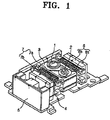
- FIG. 1 a bobbin 3 for holding the objective lenses 1 and 2 is movably supported by a holder 5 with the aid of suspension members 4.
- the bobbin 3 is driven in a focusing direction by a first magnetic circuit 6 having a focusing coil 6a and a focusing magnet 6b.
- the bobbin 3 is driven in a tracking direction by a second magnetic circuit 7 having a tracking coil 7a, wound around the bobbin 3, and a tracking magnet 7b.
- the actuator drives those two objective lenses 1 and 2 to record/reproduce information on/from a plurality of differing types of optical discs, each having different recording densities and thicknesses. More details on the optical pickup actuator illustrated in FIG 1 can be found in Korean Laid-Open Publication No. 2003-0045259 and thus, will not be provided here.
- the related art optical pick-up actuators having the above construction are often faced with a problem caused by low stiffness of the bobbin 3 holding the coils 6a and 7a. As a result, a shortage of a gain margin occurs relating to the resonance frequency of the secondary coil and secondary resonance.
- an actuator for a pick-up comprising:
- the plurality of magnets may be disposed to have opposing polarities between neighboring magnets.
- the plurality of magnets may be 2-pole magnets polarized in the tracking direction.
- the bobbin may include a pair of lens mount holes for mounting the objective lenses.
- the focusing/tilting coils may be wound in a rectangular shape to be homocentric around the lens mount holes. Further, the focusing/tilting coils may be wound to have a designated height in the focusing direction.
- the focusing/tilting coils may be disposed in parallel to each other in the tracking direction.
- the magnetic circuit may further include a plurality of internal yokes disposed inside the focusing/tilting coils, respectively, for focusing magnetic flux from the focusing/tilting coils.
- the internal yokes may be fixed to the base facing sides of the focusing/tilting coils, the sides being arranged in the tracking direction.
- the magnetic circuit may also include a plurality of external yokes fixed to the base for guiding magnetic flux from the plurality of magnets.
- the plurality of magnets may be supported by the external yokes, respectively.
- the pair of tracking coils may be installed in both outer surfaces of the bobbin to be in correspondence with the plurality of magnets, respectively.
- the tracking coils may be wound in a rectangular shape, and disposed on opposite sides from each other while being laid overlapped with neighboring magnets, respectively.
- the tracking coils can be disposed in such a manner that sides of the tracking coils, parallel to the focusing direction, interact with the magnets, respectively, to generate an electromagnetic force. In the tracking direction, each tracking coil may also lie between the focusing/tilting coils.
- the plurality of magnets may be a pair of 2-pole magnets polarized in the tracking direction, the polarized magnets being disposed opposite to each other having the bobbin therebetween.
- the bobbin may include a pair of lens mount holes for mounting the objective lenses, and the mount holes are disposed in a radial direction of a medium.
- an actuator for an optical pick-up includes a base 10, a holder 11 fixed to the base 10, a bobbin 20 with lens mount holes 21 and 23, where a plurality of objective lenses 31 and 33, possibly having different working distances, are mounted, suspensions 13 for connecting the bobbin 20 and the holder 11, and magnetic circuits for driving the bobbin 20 in a focusing, tilting, and tracking direction.
- the plurality of objective lenses 31 and 33 include a first objective lens 31 for recording/reproducing information onto/from at least one of any low density optical disc, each having different recording densities, and a second objective lens 33 for recording/reproducing information onto/from any optical disc having a higher density than the low density optical disc (hereinafter, it will be referred to as a high density optical disc).
- the first objective lens 31 may record/reproduce information onto/from an optical disc selected among low density DVDs (hereinafter, it will be referred to as a DVD), and additionally an optical disc selected among CDs (hereinafter, it will be referred to as a CD).
- the second objective lens 33 may record/reproduce information onto/from an optical disc selected among DVDs having higher recording densities than standard DVDs, e.g., HD-DVDs.
- an optical disc selected among DVDs having higher recording densities than standard DVDs e.g., HD-DVDs.
- three (or more) objective lenses having different working distances can be utilized.
- the objective lenses 31 and 33 can be installed in one bobbin 20 in a radial direction (R direction) of the optical discs. In so doing, the actuator can be made compatible with an optical pick-up utilizing a plurality of objective lenses.
- the bobbin 20 can include a first lens mount hole 21 for mounting the first objective lens 31, and a second lens mount hole 23 for mounting the second objective lens 23.
- the number of lens mount holes formed in the bobbin 20 is equal to the number of objective lenses to be mounted thereon.
- the first and second lens mount holes 21 and 22 are disposed in the R direction. And, the lens mount holes 21 and 23, as shown in FIG. 5, may have different depths, so that the objective lenses 31 and 33 mounted thereon can have different heights. That is, inside the first lens mount hole 21 is a recess 21 a that is formed at a relatively deep position from the top surface of the bobbin 20 opposite to the optical disc. This ensures that the first objective lens 31, which is a low density optical disc having a long working distance, is safely installed therein.
- a recess 23a is formed in the second lens hole 23, but this time the recess 23a is formed high enough to touch the top surface of the bobbin 20 opposite to the optical disc (or at a position that is higher than the recess 21 a formed in the first lens mount hole 21 to be closer to the top surface of the bobbin 20).
- the second objective lens 33 which is a high density optical disc having a short working distance, may be fitted to the recess 23a.
- the top surface of the bobbin 20 is opened through the lens mount holes 21, 23, and the structure of the low portion of the bobbin 20 is a hexahedron in shape, being opened through a first and a second space 25 and 26.
- the first and second spaces 25 and 26 are separated in the R direction by a barrier rib 27, e.g., in the middle between the first and second spaces 25 and 26.
- inside the first space 25 can be a first focusing/tilting coil 41 (described more fully below), and inside the second space 26 can be a second focusing/tilting coil 43 (described more fully below).
- the bobbin 20 can be movably supported by the holder 11 with the aid of suspensions 13.
- the suspensions 13 may be a spring wire that has a designated stiffness yet is elastically transformable at the same time, though the present invention is not limited thereto.
- Outside the bobbin 20 is a connecting piece 28 attached to each suspension 13.
- the bobbin 20 can be made out of plastic materials, and can be manufactured by injection molding, for example.
- Magnetic circuits can be utilized for driving the objective lenses 31 and 33 in the focusing, tracking (hereinafter, it will be referred to as R-direction), and tilt directions.
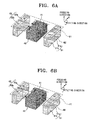
- the magnetic circuit includes a first and second focusing/tilting coils 41 and 43, a first and second tracking coils 51 and 53, and first and second polarized magnet 61 and 63.
- the first and second focusing/tilting coils 41 and 43 are installed in the R direction inside the bobbin 20, that is, in the first and second spaces 25 and 26, shown in FIG. 5, respectively.
- the first and second focusing/tilting coils 41 and 43 have a rectangular shape, being homocentric in the focusing direction.
- the first and second focusing/tilting coils 41 and 43 can be wound in the focusing direction up to a designated height, and more specifically, each coil can be wound around the first and second objective lenses 31 and 33.
- the bobbin 20 is driven in the focusing and tilting directions by a driving force generated from an interaction between a pair of short sides (which are in parallel to the R direction) of the first and second focusing/tilting coils 41 and 43 and the first and second polarized magnets 61 and 63.
- the first and second tracking coils 51 and 53 are installed, respectively, in the bobbin's outer surface to be parallel to the R direction.
- the first and second tracking coils 51 and 53 are disposed in such a manner that the center of each tracking coil 51 and 53 lies between the first and second focusing/tilting coils 41 and 43.
- the center of each polarized magnet 61 and 63 i.e., the center of the N-pole and the S-pole of each magnet lies on the same line with the center of each focusing/tilting coil 41 and 43.
- each tracking coil 51 and 53 can be wound in a rectangular shape, so the sides of the rectangular-shaped tracking coils 51 and 53 in the focusing direction are faced with the N-pole portions 61 a and 63a and the S-pole portions 61 b and 63b of the polarized magnets 61 and 63. Therefore, a driving force generated from the interaction between the first and second tracking coils 51 and 53 and the first and second polarized magnets 61 and 63 is applied to the bobbin, and as a result thereof, the bobbin is moved in the tracking direction.
- the first and second polarized magnets 61 and 63 have the bobbin 20 between them, and are disposed, respectively, at a designated distance from the bobbin's outer surfaces that are in parallel to the R direction.
- Each polarized magnet 61 and 63 has the N-pole portion 61 a and 63b, and the S-pole portion 61 b and 63a in the R direction.
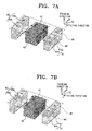
- the first and second polarized magnets 61 and 63 interact not only with the first and second focusing/tilting coils 41 and 43, but also with the first and second tracking coils 51 and 53.
- both polarized magnets 61 and 63 are involved with driving the bobbin 20 in the focusing, tilting, and tracking directions and thus, they are arranged to meet such purposes.
- the N-pole portions and the S-pole portions of the first and second polarized magnets 61 and 63 are located to be in correspondence to each other, i.e., same polarities are facing each other.
- the N-pole portion 61 a of the first polarized magnet 61 is located on the opposite side of the N-pole portion 63a of the second polarized magnet 63, having the first focusing/tilting coil 41 therebetween.
- the S-pole portion 61 b of the first polarized magnet 61 is located on the opposite side of the S-pole portion 63b of the second polarized magnet 63, having the second focusing/tilting coil 43 therebetween.
- the first and second magnets M1 and M2 may interact with the first and second focusing/tilting coils 41 and 43, with an electromagnetic force being generated from the corresponding interaction. This becomes the driving force for driving the bobbin 20 in the focusing and tilting directions. This mechanism will be described in greater detail below.
- the magnetic circuit further includes internal yokes 71 disposed inside the first and second focusing/tilting coils 41 and 43, and external yokes 73 installed in correspondence to (or next to) the first and second polarized magnets 61 and 63, respectively.
- a pair of the internal yokes 71 are disposed inside each focusing/tilting coil 41 and 43.
- the effective parts of the focusing/tilting coils 41 and 43 are disposed in the R direction.
- the internal yokes 71 can be fixed to the base 10, or combined with the base 10 as one body, and may be made out of the same material as the base 10, for example.
- the internal yokes 71 can be spaced from the focusing/tilting coils 41 and 43, and guide magnetic flux generated from the focusing/tilting coils 41 and 43 in the focusing/tilting directions, thereby maximizing an effective magnetic field intensity.
- the external yokes 73 can be fixed to the base 10 as one body with the base 10.
- the external yokes 73 are also disposed on the opposite sides from the outer surfaces of the first and second polarized magnets 61 and 63, while the inner surfaces of the first and second polarized magnets 61 and 63 face the bobbin 20.
- the external yokes 73 may support the first and second polarized magnets 61 and 63, respectively.
- the external yokes 73 guide magnetic flux of a magnetic field generated from each polarized magnet 61 and 63, and focus it towards the bobbin 20, thereby maximizing an effective magnetic field intensity.
- the first and second polarized magnets 61 and 63 are disposed on the opposite sides from each other, having the first and second focusing/tilting coils 41 and 43 therebetween.
- the first focusing/tilting coil 41 is driven by an interaction with first magnet M1
- the second focusing/tilting coil 43 is driven by an interaction with the second magnet M2.
- a movable unit including the bobbin 20, the first and second objective lens 31 and 33, the first and second focusing/tilting coils 41 and 43. and the first and second tracking coils 51 and 53 moves upward.
- the first tracking coil 51 faces the first polarized magnet 61, whose N-pole and S-pole are polarized in the R direction.
- the first tracking coil 51 has longer sides in the vertical direction, with the long sides being disposed to be in correspondence to the N-pole portion 61 a and the S-pole portion 61 b, respectively.
- those long sides effectively become tracking coils generating an electromagnetic force.
- current flowing in a counterclockwise direction is applied to the first tracking coil 51, force is applied to the left side of the long sides.
- the actuator having the bobbin 20 mounted with two objective lenses 31 and 33 is heavier than a general actuator having a bobbin mounted with one objective lens.
- the number of focusing/tilting coils 41 and 43 for driving the bobbin 20 in the focusing and tilting directions is equal to the number of objective lenses 31 and 33, and the focusing/tilting coils 41 and 43 are installed in the bobbin 20, so the outer size of the bobbin 20 has not bee increased, while a greater driving force than the general actuator can be generated.
- driving the bobbin 20 in the focusing direction becomes much easier. Therefore, when controlling the position of the bobbin 20, deterioration in sensitivity caused by an increase in weight or occurrence of secondary resonance can be prevented.
- the tracking coils 51 and 53 for driving the bobbin 20 in the tracking direction can be installed in the bobbin 20.
- the first and second polarized magnets 61 and 63 are preferably utilized. In this way, the weight of tracking coils 51 and 53 in the actuator of preferred embodiments of the present invention becomes lower than that of tracking coils in the conventional actuator.
- two objective lenses 31 and 33 were loaded in one bobbin 20.
- this is for illustrative purposes only.
- the magnetic circuit can be employed for adjusting the position of the objective lens more easily.
- Embodiments of the present invention actuator having the bobbin 20 mounted with more than one objective lens can be applied to an optical pick-up for recording/reproducing information onto/from two or more optical discs with different recording densities, such as CD, DVD, and HD-DVD, for example.
- the actuator for the optical pick-up includes one bobbin mounted with two objective lenses, and a magnetic circuit for adjusting the objective lenses in the focusing, tilting, and tracking directions.
- the magnetic circuit has a reduced number of elements, which in turn reduces the entire size of the actuator and the cost of manufacture thereof.
- the number of focusing/tilting coils for adjusting the position of each objective lens can be equal to the objective lenses used.
Claims (17)
- Actionneur pour une tête de lecture comprenant :un support (11) fixé à une base (10) ;une bobine (20) destinée à loger plusieurs lentilles de focalisation (31, 33) pour enregistrer et/ou reproduire des informations sur et/ou à partir de supports différents, chaque support ayant des densités d'enregistrement différentes ;une suspension (13) pour relier la bobine (20) et le support (11), et pour maintenir la bobine (20) de façon à ce qu'elle soit mobile ; etun circuit magnétique pour entraîner la bobine (20),caractérisé en ce que le circuit magnétique comprend :au moins un premier et un second enroulements de focalisation/inclinaison (41, 43) disposés au niveau de la bobine (20) de manière à correspondre à l'emplacement des lentilles (31, 35), et entraînant la bobine dans une direction de focalisation et/ou d'inclinaison ;au moins un premier et un second aimants polarisés (61, 63) disposés, respectivement, à une certaine distance des surfaces extérieures de la bobine qui sont parallèles à la direction de repérage (R), dans lesquels une première partie de pôle N (61a) du premier aimant polarisé (61) est située en face d'une seconde partie de pôle N (63a) du second aimant polarisé (63), le premier enroulement de focalisation/inclinaison (41) étant placé entre les deux, et une première partie de pôle S (61b) du premier aimant polarisé (61) étant située en face d'une première partie de pôle S (63b) du second aimant polarisé (63), le second enroulement de focalisation/inclinaison (43) étant placé entre les deux ; etdes enroulements de repérage (51, 53), maintenus par la bobine (20), pour générer une force d'entraînement afin d'entraîner la bobine (20) dans une direction de repérage.
- Actionneur conformément à la revendication 1, dans lequel les aimants (61, 63) sont disposés de façon à ce qu'il y ait des polarités opposées entre les aimants voisins.
- Actionneur conformément à la revendication 1 ou à la revendication 2, dans lequel les aimants (61, 63) sont des aimants à deux pôles polarisés dans la direction de repérage.
- Actionneur conformément à l'une quelconque des revendications précédentes, dans lequel la bobine (20) comprend une paire de trous de montage de lentille (21, 23) pour y monter les lentilles de focalisation (31, 33).
- Actionneur conformément à la revendication 4, dans lequel les enroulements de focalisation/inclinaison (41, 43) sont enroulés selon une forme rectangulaire de façon à être homocentriques autour des trous de montage de lentille (21, 23).
- Actionneur conformément à la revendication 5, dans lequel les enroulements de focalisation/inclinaison (41, 43) sont enroulés de manière à avoir une hauteur assignée dans la direction de focalisation.
- Actionneur conformément à l'une quelconque des revendications précédentes, dans lequel les enroulements de focalisation/inclinaison (41, 43) sont disposés parallèlement l'un à l'autre dans la direction de repérage.
- Actionneur conformément à l'une quelconque des revendications précédentes, dans lequel le circuit magnétique comprend en outre plusieurs cages internes (71) disposées à l'intérieur des enroulements de focalisation/inclinaison (41, 43), respectivement, pour concentrer le flux magnétique en provenance des bobines de focalisation/inclinaison (41, 43).
- Actionneur conformément à la revendication 8, dans lequel les cages internes (71) sont fixées à la base (10) en regard de côtés des bobines de focalisation/inclinaison (41, 43), les côtés étant disposés dans la direction de repérage.
- Actionneur conformément à l'une quelconque des revendications précédentes, dans lequel le circuit magnétique comprend en outre plusieurs cages externes (73) fixées à la base pour guider le flux magnétique en provenance des aimants (61, 63).
- Actionneur conformément à la revendication 10, dans lequel les aimants (61, 63) sont maintenus par les cages externes (73), respectivement.
- Actionneur conformément à l'une quelconque des revendications précédentes, dans lequel les enroulements de repérage (51, 53) sont disposés dans les deux surfaces extérieures de la bobine (20) de sorte que le centre de chaque enroulement de repérage (51, 53) se situe entre le centre du premier et le centre du second aimant polarisés (61, 63).
- Actionneur conformément à la revendication 12, dans lequel les enroulements de repérage (51, 53) sont enroulés selon une forme rectangulaire, et disposés l'un en face de l'autre tout en étant placés de façon à être chevauchés par les aimants voisins (61, 63), respectivement.
- Actionneur conformément à la revendication 13, dans lequel les enroulements de repérage (51, 53) sont disposés de manière à ce que leurs côtés parallèles à la direction de focalisation interagissent avec les aimants (61, 63), respectivement, afin de générer une force électromagnétique.
- Actionneur conformément à l'une quelconque des revendications 12 à 14, dans lequel chaque enroulement de repérage (51, 53) se situe entre les enroulements de focalisation/inclinaison (41, 43), dans la direction de repérage.
- Actionneur conformément à l'une quelconque des revendications précédentes, dans lequel les aimants (61, 63) sont une paire d'aimants à deux pôles polarisés dans la direction de repérage, les aimants polarisés étant disposés l'un en face de l'autre et la bobine (20) étant placé entre eux.
- Actionneur conformément à l'une quelconque des revendications précédentes, dans lequel la bobine (20) comprend une paire de trous de montage de lentille (21, 23) pour y monter les lentilles de focalisation (31, 33), et les trous de montage sont disposés dans la direction radiale dudit support.
Applications Claiming Priority (2)
| Application Number | Priority Date | Filing Date | Title |
|---|---|---|---|
| KR1020040038118A KR100555657B1 (ko) | 2004-05-28 | 2004-05-28 | 광픽업용 액츄에이터 |
| KR2004038118 | 2004-05-28 |
Publications (3)
| Publication Number | Publication Date |
|---|---|
| EP1600960A2 EP1600960A2 (fr) | 2005-11-30 |
| EP1600960A3 EP1600960A3 (fr) | 2006-06-21 |
| EP1600960B1 true EP1600960B1 (fr) | 2008-01-23 |
Family
ID=34941440
Family Applications (1)
| Application Number | Title | Priority Date | Filing Date |
|---|---|---|---|
| EP05253191A Expired - Fee Related EP1600960B1 (fr) | 2004-05-28 | 2005-05-24 | Tête de lecture optique et procédé, et appareil de reproduction et/ou d'enregistrement l'utilisant |
Country Status (5)
| Country | Link |
|---|---|
| US (1) | US7561497B2 (fr) |
| EP (1) | EP1600960B1 (fr) |
| KR (1) | KR100555657B1 (fr) |
| CN (1) | CN100353432C (fr) |
| DE (1) | DE602005004443T2 (fr) |
Families Citing this family (5)
| Publication number | Priority date | Publication date | Assignee | Title |
|---|---|---|---|---|
| KR100710756B1 (ko) * | 2004-12-22 | 2007-04-24 | 삼성전자주식회사 | 광픽업용 액츄에이터 및 광기록 및/또는 재생장치 |
| KR100677746B1 (ko) | 2005-03-11 | 2007-02-02 | 삼성전자주식회사 | 광기록/재생기기의 광픽업장치 |
| KR101222860B1 (ko) * | 2005-09-01 | 2013-01-16 | 삼성전자주식회사 | 광픽업장치 |
| KR100760205B1 (ko) * | 2006-08-02 | 2007-09-20 | 삼성전자주식회사 | 광픽업용 액추에이터 |
| US7729212B2 (en) * | 2006-10-05 | 2010-06-01 | Panasonic Corporation | Objective lens driving device, optical pickup device, and optical disk drive |
Family Cites Families (13)
| Publication number | Priority date | Publication date | Assignee | Title |
|---|---|---|---|---|
| EP1316946A3 (fr) * | 1995-11-13 | 2004-10-27 | Quantum Corporation | Dispositif d'ajustement du zenith de têtes dans des lecteurs de bandes |
| JP3726979B2 (ja) | 1995-11-29 | 2005-12-14 | シャープ株式会社 | 光ピックアップ |
| JPH09171630A (ja) | 1995-12-20 | 1997-06-30 | Akai Electric Co Ltd | 光学ピックアップの対物レンズ支持装置 |
| JPH09297927A (ja) * | 1996-05-07 | 1997-11-18 | Sharp Corp | 光ピックアップ装置 |
| WO1998002874A1 (fr) * | 1996-07-17 | 1998-01-22 | Sony Corporation | Dispositif de captage optique et d'enregistrement et/ou de reproduction pour disque optique |
| JP3601756B2 (ja) | 1998-06-30 | 2004-12-15 | 日本ビクター株式会社 | 光ピックアップ |
| JP2002245650A (ja) | 2001-02-20 | 2002-08-30 | Toshiba Corp | 対物レンズ駆動装置および光ディスク装置 |
| JP2003045054A (ja) * | 2001-07-31 | 2003-02-14 | Sumida Corporation | 光ピックアップ |
| KR100636127B1 (ko) | 2001-12-01 | 2006-10-19 | 삼성전자주식회사 | 광픽업용 액츄에이터 |
| JP2003196865A (ja) * | 2001-12-27 | 2003-07-11 | Mitsumi Electric Co Ltd | 光ピックアップ装置 |
| EP1355301A3 (fr) * | 2002-04-20 | 2006-03-29 | Lg Electronics Inc. | Actionneur pour tête optique |
| TWI227484B (en) | 2002-08-24 | 2005-02-01 | Samsung Electronics Co Ltd | Objective lens driving apparatus for optical pickup |
| TW200405314A (en) * | 2002-08-24 | 2004-04-01 | Samsung Electronics Co Ltd | Objective lens driving apparatus for optical pickup |
-
2004
- 2004-05-28 KR KR1020040038118A patent/KR100555657B1/ko not_active IP Right Cessation
-
2005
- 2005-05-24 EP EP05253191A patent/EP1600960B1/fr not_active Expired - Fee Related
- 2005-05-24 DE DE602005004443T patent/DE602005004443T2/de active Active
- 2005-05-26 US US11/137,517 patent/US7561497B2/en not_active Expired - Fee Related
- 2005-05-30 CN CNB2005100746681A patent/CN100353432C/zh not_active Expired - Fee Related
Also Published As
| Publication number | Publication date |
|---|---|
| EP1600960A2 (fr) | 2005-11-30 |
| CN100353432C (zh) | 2007-12-05 |
| US20050265141A1 (en) | 2005-12-01 |
| EP1600960A3 (fr) | 2006-06-21 |
| DE602005004443D1 (de) | 2008-03-13 |
| CN1702743A (zh) | 2005-11-30 |
| KR100555657B1 (ko) | 2006-03-03 |
| DE602005004443T2 (de) | 2008-08-21 |
| US7561497B2 (en) | 2009-07-14 |
| KR20050112726A (ko) | 2005-12-01 |
Similar Documents
| Publication | Publication Date | Title |
|---|---|---|
| KR100636127B1 (ko) | 광픽업용 액츄에이터 | |
| EP1600960B1 (fr) | Tête de lecture optique et procédé, et appareil de reproduction et/ou d'enregistrement l'utilisant | |
| US7619951B2 (en) | Optical pickup actuator and optical recording and/or reproducing apparatus | |
| US7643386B2 (en) | Optical pickup actuator and optical recording and/or reproducing apparatus | |
| US7668049B2 (en) | Optical pickup actuator and optical recording/reproducing apparatus | |
| US7372786B2 (en) | Optical pickup actuator | |
| US7453656B2 (en) | Recording and/or reproducing apparatus with an optical pickup actuator having high thrust | |
| KR100689035B1 (ko) | 광픽업용 액츄에이터 및 광기록 및/또는 재생장치 | |
| US20050259527A1 (en) | Optical component triaxial actuator and recording/reproducing apparatus using the same | |
| KR100488039B1 (ko) | 광픽업 액츄에이터 | |
| KR100479617B1 (ko) | 광픽업 액츄에이터 | |
| KR100624860B1 (ko) | 광 디스크 드라이브 | |
| KR100630774B1 (ko) | 고추력 자기회로 및 상기 자기회로를 이용한 광픽업액츄에이터 | |
| KR20050112010A (ko) | 광픽업 액츄에이터 및 이를 채용한 광디스크 드라이브 |
Legal Events
| Date | Code | Title | Description |
|---|---|---|---|
| PUAI | Public reference made under article 153(3) epc to a published international application that has entered the european phase |
Free format text: ORIGINAL CODE: 0009012 |
|
| AK | Designated contracting states |
Kind code of ref document: A2 Designated state(s): AT BE BG CH CY CZ DE DK EE ES FI FR GB GR HU IE IS IT LI LT LU MC NL PL PT RO SE SI SK TR |
|
| AX | Request for extension of the european patent |
Extension state: AL BA HR LV MK YU |
|
| PUAL | Search report despatched |
Free format text: ORIGINAL CODE: 0009013 |
|
| AK | Designated contracting states |
Kind code of ref document: A3 Designated state(s): AT BE BG CH CY CZ DE DK EE ES FI FR GB GR HU IE IS IT LI LT LU MC NL PL PT RO SE SI SK TR |
|
| AX | Request for extension of the european patent |
Extension state: AL BA HR LV MK YU |
|
| 17P | Request for examination filed |
Effective date: 20060713 |
|
| 17Q | First examination report despatched |
Effective date: 20060925 |
|
| AKX | Designation fees paid |
Designated state(s): DE GB NL |
|
| GRAP | Despatch of communication of intention to grant a patent |
Free format text: ORIGINAL CODE: EPIDOSNIGR1 |
|
| GRAS | Grant fee paid |
Free format text: ORIGINAL CODE: EPIDOSNIGR3 |
|
| GRAA | (expected) grant |
Free format text: ORIGINAL CODE: 0009210 |
|
| AK | Designated contracting states |
Kind code of ref document: B1 Designated state(s): DE GB NL |
|
| REG | Reference to a national code |
Ref country code: GB Ref legal event code: FG4D |
|
| REF | Corresponds to: |
Ref document number: 602005004443 Country of ref document: DE Date of ref document: 20080313 Kind code of ref document: P |
|
| PLBE | No opposition filed within time limit |
Free format text: ORIGINAL CODE: 0009261 |
|
| STAA | Information on the status of an ep patent application or granted ep patent |
Free format text: STATUS: NO OPPOSITION FILED WITHIN TIME LIMIT |
|
| 26N | No opposition filed |
Effective date: 20081024 |
|
| PGFP | Annual fee paid to national office [announced via postgrant information from national office to epo] |
Ref country code: GB Payment date: 20140423 Year of fee payment: 10 |
|
| PGFP | Annual fee paid to national office [announced via postgrant information from national office to epo] |
Ref country code: NL Payment date: 20140423 Year of fee payment: 10 Ref country code: DE Payment date: 20140423 Year of fee payment: 10 |
|
| REG | Reference to a national code |
Ref country code: DE Ref legal event code: R119 Ref document number: 602005004443 Country of ref document: DE |
|
| GBPC | Gb: european patent ceased through non-payment of renewal fee |
Effective date: 20150524 |
|
| REG | Reference to a national code |
Ref country code: NL Ref legal event code: MM Effective date: 20150601 |
|
| PG25 | Lapsed in a contracting state [announced via postgrant information from national office to epo] |
Ref country code: DE Free format text: LAPSE BECAUSE OF NON-PAYMENT OF DUE FEES Effective date: 20151201 Ref country code: GB Free format text: LAPSE BECAUSE OF NON-PAYMENT OF DUE FEES Effective date: 20150524 Ref country code: NL Free format text: LAPSE BECAUSE OF NON-PAYMENT OF DUE FEES Effective date: 20150601 |