BACKGROUND OF THE INVENTION
TECHNICAL FIELD OF THE INVENTION
The present invention relates to a magnetic tape and a method
for producing the magnetic tape and, more particularly, relates
to a magnetic tape and a method for producing the magnetic tape
which is excellent in running durability and capable of
remarkably suppressing an increase in dropouts and a decrease
in output after repeated FF/REW running.
DESCRIPTION OF THE RELATED ART
Magnetic recording media have been used for various
applications as recording tape, videotape, data-recording tape,
etc. Yearly, these are being made available as ever-higher
density magnetic recording media and shorter recording
wavelengths, while various recording methods have been studied
from analog method to digital method.
In particular, magnetic recording media in which a
ferromagnetic metal powder mainly containing iron is coated
together with a binding agent on a non-magnetic support have
been used mainly as visual data recording media for commercial
use due to excellent cost performance. High electromagnetic
conversion characteristics are required for these magnetic
recording media for recording visual data for commercial use,
and recorded images and data are marketable products, therefore,
running durability is required that can withstand severe use
under various environmental conditions compared with those for
general consumers. To be more specific, required running
durability includes suppression of dropout (DO), clogging and
decreased output.
For the purpose of decreasing the number of DO, a magnetic
recording medium has been disclosed in JP-A-8-279148, in which
a volume per 0.03mm of the magnetic layer part projected from
the apex of the maximum convex part of a non-magnetic support
is greater than 0 but less than 100µm3 or the number of cracks
at the edge of a magnetic layer is 0 to 100 cracks/mm.
For the purpose of improving the reliability of
electromagnetic conversion characteristics, DO, and durability
and also raising productivity, a magnetic recording medium has
been disclosed in JP-A-2000-207732, which is not projected from
the lowest end of a lower non-magnetic layer.
When a magnetic tape runs on VTR etc., the majority of VTRs,
etc., restrict the edge of magnetic tape, by which the edge is
always running in contact with the restriction guide. Such
restriction is responsible for an increase in the number of DO
or a marked decrease in output at the turn-back point before
and after the running of the magnetic tape, particularly when
a durability running test is conducted by repeating FF/REW
running. This guide restriction has become increasingly severe
due to the recent remarkable improvement in recording density.
Therefore, a magnetic tape is now required, which has excellent
running durability under a severe guide restriction.
SUMMARY OF THE INVENTION
An object of the present invention is to provide a magnetic
tape which is excellent in running durability and capable of
markedly suppressing an increase in the number of dropouts and
a decrease in output even after repeated FF/REW running and a
method for producing the same.
As a result of a diligent examination, it was found that
when magnetic tapes are produced by cutting an wide raw film
of magnetic tape by use of a cutting device mainly having an
upper blade and a lower blade, fine particles (slit dust) adhere
to the cut surface of the thus obtained magnetic tape and the
fine particles move to the surface of the magnetic tape due to
the guide restriction, which results in an increase in the number
of DO, a decrease in output, etc. A more detailed examination
also found that slit dust adhered to the non-restraint side cut
surface (also called upper blade surface) during cutting heavily
adheres to the cut surface of the magnetic tape again. Further,
when the maximum convex degree of the magnetic layer on the
non-restraint side cut surface was great, the tape was damaged
by a touch roller when reeled after cutting and consequently
fine particles were found to more heavily adhere to the cross
section of the magnetic tape.
To be specific, the present invention can be described as
follows.
The present invention can provide a magnetic tape which is
excellent in running durability and capable of remarkably
suppressing an increase in the number of dropouts and a decrease
in output even after repeated FF/REW running and a method for
producing the magnetic tape. Further, in order to remove
adherence of fine particles, it can be considered that a tape
after a slit is allowed to come into contact with a cleaning
tissue, thereby reducing the amount of adhering particles.
However, it is impossible to sufficiently remove fine particles
adhering to the cut surface of a magnetic tape, and there is
a problem in increasing the production cost. Accordingly, even
if using a cleaning tissue, it is impossible to attain the object
of the present invention.
BRIEF DESCRIPTION OF THE DRAWINGS
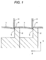
FIG.1 shows a cross section of the cut part of the cutting
device, which is viewed so that the machine direction of the
wide raw film of magnetic tape is in the vertical direction on
the paper surface.
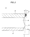
FIG.2 is a cross sectional view of the magnetic tape
illustrating the maximum convex degree of the magnetic layer
according to the present invention.
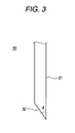
FIG.3 is a cross sectional view of the upper blade
illustrating the blade angle according to the present invention.
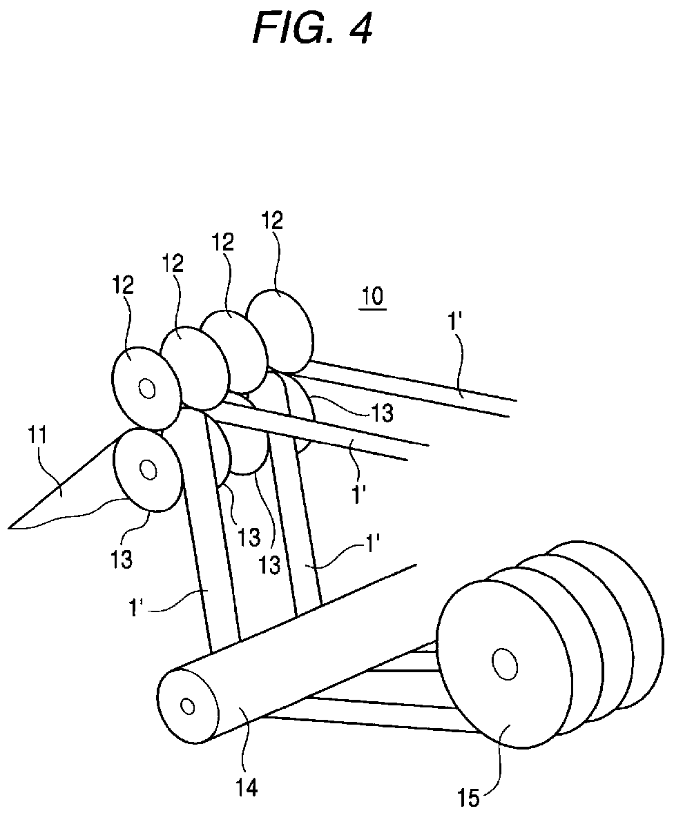
FIG. 4 is a view illustrating one example of the cutting device
used in the present invention.
DETAILED DESCRIPTION OF THE INVENTION
In the present invention, a restraint side cut surface is
a surface of the side where an wide raw film of magnetic tape
is restricted by the lower blade and cut by the upper blade,
whereas a non-restraint side cut surface is a surface opposite
the restraint side cut surface and a surface of the side where
a wide raw film of magnetic tape is not restrained by the lower
blade and cut by the upper blade.
An additional description will be made with reference to
FIG.1. FIG.1 is a cross section of a cut part of the cutting
device which is viewed so that the machine direction of the wide
raw film of magnetic tape is in the vertical direction on the
paper surface.
X denotes the width direction of an wide raw film of magnetic
tape, and Y denotes the thickness direction of an wide raw film
of magnetic tape.
The restraint side cut surface 4 is a surface of the side
where the original magnetic tape 1 is restrained by the lower
blade 2 and cut by the upperblade 3. It is a cut surface restrained
in the direction of Y.
The non-restraint side cut surface 5 is a surface opposite
the restraint side cut surface, and a surface of the side where
the original magnetic tape 1 is not restrained by the lower blade
2 and cut by the upper blade 3. it is a cut surface not restrained
in the direction of Y.
FIG.2 is a cross sectional view of the magnetic tape for
illustrating a maximum convex degree of the magnetic layer
according to the present invention. In FIG.2, the magnetic tape
21 of the present invention has a magnetic layer 23 which contains
at least a ferromagnetic powder and a binding agent on one surface
of a support 22 and a back layer 24 on the other surface. When
an wide raw film of magnetic tape is slit along the machine
direction and a line 26 is drawn vertically to the width direction
of a magnetic tape from the apex of a maximum convex part 25
of a support 22 on the non-restraint side cut surface, a maximum
convex degree of the magnetic layer is a length L in the width
direction of the magnetic tape which is the degree of the magnetic
layer part 27 projected from the maximum convex part 24 divided
by this line 26. Further, the maximum convex part 25 of the
support 22 is the furthest end of a part which contacts with
the end line of the cut end when a line vertical to the width
direction of the magnetic tape is scanned with respect to the
end line of the cut end obtained by projecting so that the cut
surface of the magnetic tape 21 is vertical to the paper surface.
A magnetic tape of the present invention must meet the
following conditions of (1) and (2),
In the condition (1), when the maximum convex degree of the
magnetic layer exceeds 1.0µm, particles with a particle size
of 1.0µm or greater heavily adhere to the cut surface of a magnetic
tape, which is not favorable. Thus, it is favorable that the
maximum convex degree of the magnetic layer is 0 to 0.5µm.
Further, the maximum convex degree of the magnetic layer
can be measured simply by using a commercially available
microscope, for example, by a laser microscope made by JEOL Ltd.
In the condition (2), the total of adhering particles exceeds
100 for each 20mm in the length direction of a magnetic tape,
which results in an increase in the number of dropouts and a
decrease in output, thereby making it impossible to attain the
object of the present invention. It is preferable that the number
of adhering particles is 50 particles/20mm or lower. In the
present invention, the total number of adhering particles is
made to be 100/20mm or lower, by which an increase in the number
of dropouts can be markedly suppresseddue to repetition of FF/REW
running, in particular.
The number of adhering particles can be counted through
photography by a scanning electron microscope (SEM). A
preferable photographic magnification is 1000 to 2000 times.
Where there is a concern when adhering particles vary in the
density presence depending on sites, it is preferable that the
site is randomly selected for one sample to observe at least
a 20mm-long field in the length direction of a magnetic tape,
by which adhering particles are counted and the mean value is
calculated. In addition, the thus photographed adhering
particles can be analyzed for composition by conducting analysis
by EPMA (Electron Probe X-ray Micro Analyzer) at the same time
with SEM photography.
In order to provide a magnetic tape that can meet the
above-described conditions of (1) and (2), it is necessary to
establish a blade angle of the upper blade forming the
non-restraint side cut surface of the magnetic tape at 50 to
80°, as one embodiment.
FIG.3 is a cross sectional view of the upper blade for
explaining the angle of the blade in the present invention. The
upper blade 30 used in the present invention is, for example,
a linear flat plate-like single-edged cutting tool equipped with
an edge back surface 31 forming the restraint side cut surface
of the magnetic tape and a blade surface 32 forming the
non-restraint side cut surface, and the blade angle described
in the present invention is an angle formed by the edge back
surface 31 and the blade surface 32.
Keeping the blade angle at 80° or lower makes it possible
to suppress the maximum convex degree of the magnetic layer at
1.0µm or lower and reduce the number of adhering particles.
Further, making the blade angle even at less than 50° can suppress
the maximum convex degree of the magnetic layer at 1.0µm or lower .
However, when an wide raw film of magnetic tape is slit, the
magnetic layer rises toward the upper blade, thereby causing
unstable reeling of cut tapes (greater bounce on a touch roller)
which is not favorable for commercial use. A preferable blade
angle is 60 to 80°.
A cutting device used in the present invention shall not
be particularly restricted, and may be a device as long as it
can cut a wide raw film of magnetic tape by an upper blade and
a lower blade to produce a plurality of narrow magnetic tapes
having a predetermined width. For example, as shown in FIG.4,
a device 10 dealing with the raw film 11 of magnetic tapes in
which many upper blades 12 and many lower blades 13 are faced
to each other, and the thus obtained magnetic tape 1' is reeled
up through a guide roller 14 while being pressed to the outer
circumferential surface of a hub 15 by a touch roller (not
illustrated).
Conditions of slitting include slit speed, mating depth,
blade strike, peripheral speed ratio of upper blade to lower
blade (peripheral speed of upper blade with respect to that of
lower blade), continuous use time of slit blades, etc.
It is preferable that the slit speed is faster, to be more
specific, in the range of 150 to 400m/minute, preferably 250
to 350m/minute, and more preferably 280 to 330m/minute. A
preferable mating depth is 0.25 to 0.7mm and a more preferable
mating depth depends on combination of other slit conditions.
A preferable blade strike is 40 to 120µm.
A preferable peripheral speed ratio of the upper blade to
the lower blade is, to be more specific, 1.00 to 1.05, and a
more preferable speed depends on combination with other slit
conditions, as with the above-described mating depth.
A magnetic tape of the present invention is obtained by
slitting an wide raw film of magnetic tape along the machine
direction, and the entire thickness is generally 3 to 20µm,
preferably 4 to 10µm for mass production, and more preferably
4 to 8µm. A description will be made about the constituent
elements of the magnetic tape of the present invention.
Supports that can be used in the present invention include
a polyethylene naphtalate (PEN), a polyethylene terephthalate
(PET), a polyamide, polyimide, a polyamide-imide, an aromatic
polyamide and a polybenzoxazole produced by biaxial orientation.
These supports may include those previously treated by corona
discharge, plasma polymerization, simple adhesion or heating.
Further, supports usable in the present invention are preferably
provided with a center line average surface roughness 0.1 to
20nm, with the cutoff value of 0.25mm, or 1 to 10nm as a preferable
range, and also provided with an excellent surface smoothness.
In addition, it is preferable that the supports are not only
small in center line average surface roughness but also free
from bulky projections exceeding 1µ. These supports are 4 to
15µm in thickness and preferably 4 to 9µm. Where it is thin,
the irregularity of the back layer is easily reflected due to
tension during handling, and use of a high-Tg polyurethane resin
in a magnetic layer makes it possible to effectively prevent
such reflection***1). Where the supports are 7µm or lower in
thickness, it is preferable to use aromatic polyamides such as
PEN and aramid.
Further, the magnetic tape of the present invention can be
provided with a non-magnetic layer between a support and a
magnetic layer. The non-magnetic layer is a substantially
non-magnetic layer containing a non-magnetic power and a binding
agent. The non-magnetic layer must be substantially
non-magnetic so as not to affect the electromagnetic conversion
characteristics of the magnetic layer thereon, but do not pose
any particular problem, if it contains a magnetic powder in such
a small amount which does not affect the electromagnetic
conversion characteristics of the magnetic layer. The
non-magnetic layer usually contains a lubricant, in addition
to these compositions.
Non-magnetic powders that can be used in the non-magnetic
layer include non-magnetic inorganic powders and carbon blacks,
for example. Of non-magnetic inorganic powders, those which
are relatively hard are preferable and those with Mohs hardness
exceeding 5 are preferable (more preferably 6 or more).
Non-magnetic inorganic powders include, for example, an
α-alumina, a β-alumina, a γ-alumina, a silicon carbide, a chromic
oxide, a serium oxide, an α-ferric oxide, a corundum, a silicon
nitride, a titanium carbide, a titanium dioxide, a silicon
dioxide, a boron nitride, a zinc oxide, a calcium carbonate,
a calcium sulfate and a barium sulfate. These may be used solely
or in combination. Of these powders, a titanium oxide, an
α-alumina, an α-ferric oxide or a chromic oxide is preferable.
A preferable mean particle size of the non-magnetic inorganic
powder is 0.01 to 1.0µm (more preferably 0.01 to 0.5µm and
particularly preferably 0.02 to 0.1µm) Further, preferable
non-magnetic powders are those in which 3 to 25% by weight
(preferably 3 to 20% by weight) is a composition which is 5 or
higher in Mohs hardness (more preferably 6 or higher in Mohs
hardness), namely those that can be used as an abrasive.
Carbon black used in the non-magnetic layer is added to
non-magnetic inorganic powders for the purpose of imparting an
electric conductivity to the magnetic layer to prevent the
electric charge and also securing the surface smoothness of the
magnetic layer formed on the non-magnetic layer. The carbon
black usable in the non-magnetic layer is preferably 35nm or
lower in mean particle size (more preferably 10 to 35nm). It
is also preferable that the carbon black is 5 to 500 m2/g in
specific surface area (more preferably 50 to 300m2/g). A
preferable DBP absorbing quantity is 10 to 1000mL/100g (more
preferably 50 to 300mL/100g). Further, it is preferable that
pH is 2 to 10, the moisture content is 0.1 to 10% and the tape
density is 0.1 to 1g/cc.
Carbon blacks produced by various methods are usable in the
present invention and include a furnace black, a thermal black,
an acetylene black, a channel black and a lamp black.
Commercially available carbon blacks include, for example, Black
Pearls 2000, 1300, 1000, 900, 800, 700 and Vulcan XC-72 (made
by Cabot Corporation) ; #35, #50, #55, #60 and #80 (made by Asahi
Carbon Co., Ltd.); #3950B, #3750B, #3250B, #2400B, #2300B, #1000,
#900, #40, #30 and #10B (made by Mitsubishi Chemical
Corporation); Conductex SC, Raven, 150, 50, 40, 15 (made by
Columbia Carbon); Ketjen black EC, Ketjen black ECDJ-500 and
Ketjen black ECDJ-600 (made by Lion Akzo Co. Ltd.).
Carbon black is usually added to the non-magnetic layer at
3 to 25 parts by weight with respect to 100 parts by weight of
all non-magnetic inorganic powders, preferably at 4 to 20 parts
by weight and more preferably at 5 to 15 parts by weight.
Binding agents usable in the non-magnetic layer include,
for example, thermoplastic resins, thermosetting resins,
reactive resins or their mixtures. Thermoplastic resins
include, for example, a vinyl chloride, a vinyl acetate, a vinyl
alcohol, a maleic acid, an acrylic acid, an acrylic ester, a
vinylidene chloride, an acrylonitrile, a methacrylic acid, a
methacrylic acid ester, a styrene, butadiene, an ethylene, a
vinyl butyral, a vinyl acetal, and polymers or copolymers
containing a vinyl ether as a constitutional unit. Copolymers
include, for example, a vinyl chloride/vinyl acetate copolymer,
a vinyl chloride/vinylidene chloride copolymer, a vinyl
chloride/acrylonitrile copolymer, an acrylic
ester/acrylonitrile copolymer, an acrylic ester/vinylidene
chloride copolymer, an acrylic ester/styrene copolymer, a
metaacrylic ester/acrylonitrile copolymer, a metaacrylic
ester/vinylidene chloride copolymer, a metaacrylic
ester/styrene copolymer, a vinylidene chloride/acrylonitrile
copolymer, a butadiene/acrylonitrile copolymer, a
styrene/butadiene copolymer, and a chlorovinyl ether/acrylic
ester copolymer.
In addition to the above described binding agents, polyamide
resins, cellulose resins (a cellulose acetate butylate, a
cellulose diacetate, a cellulose propyonate, a nitrocellulose,
etc.), a polyvinyl fluoride, a polyester resin, a polyurethane
resin and various rubber-based resins may be used.
Further, thermosetting resins and reactive resins include,
for example, a phenol resin, an epoxy resin, a polyurethane
thermosetting resin, a urea resin, a melamine resin, an alkyd
resin, an acryl reactive resin, a formaldehyde resin, a silicone
resin, an epoxy/polyamide resin, a mixture of a polyester resin
with a polyisocyanate prepolymer, a mixture of a polyester polyol
with a polyisocyanate and a mixture of a polyurethane with a
polyisocyanate.
The above-described polyisocyanates include, for example,
isocyanates such as a tolylenediisocyanate, a
4,4'-diphenylmethanedi isocyanate, a hexamethylene
diisocyanate, an xylylene diisocyanate, a
naphthylene-1,5-diisocyanate, an o-toluidine diisocyanate, an
isophorone diisocyanate and a triphenylmethane triisocyanate,
products of these isocyanates and polyalcohols, and a
polyisocyanate produced by condensation of isocyanates.
The above polyurethane resins include known compounds with
structures such as a polyester polyurethane, a polyether
polyurethane, a polyether polyester polyurethane, a
polycarbonate polyurethane, a polyester polycarbonate
polyurethane and a polycaprolactone polyurethane.
In the present invention, it is preferable that binding
agents usable in the non-magnetic layer are combinations of
polyurethane resins with at least one type of resin selected
from a vinyl chloride resin, vinyl chloride/vinyl
acetatecopolymer, vinyl chloride/vinyl acetate vinyl alcohol
copolymer, vinyl chloride/vinyl acetate anhydrous maleic acid
copolymer and nitrocellulose, or the combinations to which
polyisocyanate is combined as a curing agent.
Preferable binding agents are those for which at least one
polar group selected from -COOM, -SO3M, -OSO3M, -P=O(OM)2,
-O-P=O(OM)2 (M represents a hydrogen atom or an alkali metal),
-OH, -NR2, -N+R3 (R represents a hydrocarbon group), an expoxy
group, -SH and -CN is introduced by copolymerization or addition
reaction, whenever necessary, for obtaining an improved
dispersibility and imparting durability to the thus obtained
layer. It is also preferable that the polar group is introduced
to the binding agent in a quantity of 10-1 to 10-8 mol/g (more
preferably 10-2 to 10-6 mol/g).
A binding agent usable in the non-magnetic layer is usually
added in 5 to 50 parts by weight (preferably 10 to 30 parts by
weight) with respect to 100 parts by weight of the non-magnetic
powder. Further, where a vinyl chloride resin, a polyurethane
resin and a polyisocyanate are combined in the non-magnetic layer
as a binding agent, it is preferable that the vinyl chloride
resin, the polyurethane resin and the polyisocyanate are
contained in all binding agents respectively 5 to 70% by weight,
2 to 50% by weight and 2 to 50% by weight.
A lubricant is added to the non-magnetic layer for the purpose
of lowering the friction between the magnetic surface and the
magnetic head or between the guide pole of the drive and the
cylinder and maintaining a smooth sliding condition after it
oozes out on the surface of the magnetic layer. The lubricant
includes, for example, an aliphatic carboxylic acid such as a
fatty acid and a fatty acid ester. The fatty acid includes,
for example, an acetic acid, a propionic acid, an octanoic acid,
a 2-ethylhexanoate, an lauric acic, a myristic acid, a stearic
acid, a palmitic acid, a behenic acid, an arachidic acid, an
oleic acid, an linoleic acid, an linolenic acid, an elaidic acid,
a palmitoleic acid etc., and their mixtures.
Further, fatty acid esters include, for example, a
butylstearate, a sec-butylstearate, an isopropyl stearate, a
butyloleate, an amylstearate, a 3-methylbutylstearate, a
2-ethylhexylstearate, a 2-hexyldecile stearate, a
butylpalmitate, a 2-ethylene hexylmyristate, a mixture of a
butylstearate with a butylpalmitate, an oleyloleate, a
butoxyethylstearate, a 2-butoxy-1-propylstearate, an acylated
dipropylene glycol monobutyl ether with a stearic acid, a
diethyleneglycol dipalmitate, a hexamethylene diol which is
acylated with a myristic acid to mede into a diol, and various
ester compounds such as oleates of glycerin. These compounds
may be used solely or in combination. The lubricant is usually
added to the non-magnetic layer in 0.2 to 20 parts by weight
with respect to 100 parts by weight of all non-magnetic powders.
A magnetic layer is in principle made up of a ferromagnetic
powder and a binding agent. Further, the magnetic layer usually
contains a lubricant, an electrically conductive powder (for
example, carbon black) and an abrasive. Ferromagnetic powders
include, for example, a γ-Fe2O3, a Fe3O4, a FeOx (x=1.33 to 1.5),
a CrO2, a Co-containing γ-Fe2O3, a Co-containing FeOx (x=1.33
to 1.5), a ferromagnetic alloy powder (ferromagnetic metal
powder) mainly made up of Fe, Ni or Co (75% or greater) and a
plate-form hexagonalferrite powder. In the present invention,
it is preferable that a ferromagnetic metal powder or aplate-form
hexagonal ferrite powder is used as a ferromagnetic powder. A
ferromagnetic metallic powder is particularly preferable.
The above-described ferromagnetic metal powder is
preferably 30 to 70m2/g in specific surface area of the particles
and 50 to 300 Angstrom in crystallite size determined by X-ray
diffraction. Where the specific surface area is excessively
small, it is difficult to attain a high-density recording
sufficiently, and where it is excessively large, it is difficult
to attain a sufficient dispersion and therefore it is impossible
to form a smooth and flat surface magnetic layer, thereby
resulting in failure in responding to the high-density recording.
The ferromagnetic metal powder must contain at least Fe.
To be more specific, it is a single metal or an alloy mainly
made up of Fe, Fe-Co, Fe-Ni, Fe-Zn-Ni or Fe-Ni-Co. Further,
it may be made of Fe alone. Regarding the magnetic
characteristics, the ferromagnetic metal powder is 110emu/g (A·
m2/kg) or greater, preferably 120A·m2/kg or more and 170A·m2/kg
or less in saturated magnetizing quantity (σs) for attaining
the high recording density. Further, the coercitivity (Hc) is
1450 to 2650 oersted (Oe) (116-212kA/m), preferably 1500 to 2500
Oe (120 to 200kA/m). The mean long-axis length of the powder
determined by transmission electronmicroscope is 0.5µm or lower,
preferably 0.01 to 0.3µm, and the axial ratio (long axis length
to short axis length, aspect ratio is 5 or greater and 20 or
lower, preferably 5 to 15. Nonmetals such as B, C, Al, Si and
P, their salts or oxides is sometimes added to the composition
to further improve the characteristics. In general, an oxide
layer is formed to make particle surfaces of these metal powders
chemically stable.
The plate-form hexagonal ferrite powder used in the present
invention is 25 to 65m2/g in specific surface area, 2 to 15 in
plate form ratio (plate diameter to plate thickness) and 0.02
to 1.0µm in mean plate diameter. The plate-form hexagonal ferrite
powder has a difficulty in being subjecting to the high-density
recording, due to the same reason as the ferromagnetic metal
powder, where the particle size is excessively large or small.
The plate-form hexagonal ferrite is a flat plate-form
ferromagnetic body provided with an easily magnetizing axis in
the direction vertical to the flat plate surface, and includes,
for example, barium ferrite, strontium ferrite, lead ferrite,
calcium ferrite and their derivative substitutions such as cobalt,
etc. Of these substances, particularly preferable are a cobalt
derivative substitution of barium ferrite and a cobalt derivative
substitution of strontium ferrite. Further, elements such In,
Zn, Ge, Nb and V may be added, whenevernecessary, totheplate-form
hexagonal ferrite for the purpose of improving the
characteristics. In addition, regarding the magnetic
characteristics, the plate-form hexagonal ferrite powder must
be of a particle size as described above and also at least 50A·
m2/kg or greater, and preferably 53A·m2/kg or greater in saturated
magnetizing quantity (σs) for the purpose of attaining the
high-density recording. It is also 700 to 2000 Oe (56 to 160kA/m)
in coercitivity, and preferably in the range 900 to 1600 Oe (from
72 to 128kA/m).
It is preferable that the ferromagnetic powder contains
moisture 0.01 to 2% by weight. It is preferable that the moisture
content is optimized in accordance with types of binding agents.
It is also preferable that the ferromagnetic powder is optimized
for pH in accordance with the combination of the binding agent
to be used, and the pH is usually 4 to 12 and preferably 5 to
10. Further, it is preferable that the ferromagnetic powder
is partially coated on the surface withAl, Si, P or their oxide.
In giving the surface treatment, the coating agent is usually
added 0.1 to 10% by weight with respect to the ferromagnetic
powder. Since thus coated ferromagnetic powder can be
suppressed for the absorption of a lubricant such as fatty acid
to 100mg/m2 or lower, desired effects can be obtained even when
the lubricant is added to the magnetic layer in a small quantity.
The ferromagnetic powder may contain soluble inorganic ions such
as Na, Ca, Fe, Ni, and Sr, but it is preferable that the content
of these ions should be kept to the lowest possible extent. The
characteristics will not usually be affected where the content
is 5000ppm or lower. Further, the above-described ferromagnetic
powder and the method for producing the same have been disclosed,
for example, in Japanese Unexamined Published Patent Application
No. H7-22224.
The ferromagnetic powder used in the present invention is
preferably that treated by substances known as a sintering
preventing agent such as Al, Si, P, Ti, and rare earth elements
(Sc, Y, La, Ce, Pr, Nd, Pm, Sm, Eu, Gd, Tb, Dy, Ho, Er, Tm, Yb
and Lu). It is preferable that in the present invention such
powder is at least treated with Y (yttrium). The above sintering
preventing agent has been disclosed in Japanese Unexamined
Published Patent Application No. S52-134858, Japanese
Unexamined Published Patent Application No. S56-114833,
Japanese Unexamined Published Patent Application No. S57-73105,
Japanese Unexamined Published Patent Application No. H6-25702
and Japanese Unexamined Published Patent Application No.
H6-36265.
Lubricants described as those usable in the non-magnetic
layer may be used. A lubricant is usually added to the magnetic
layer 0.2 to 20 parts by weight (preferably 0.25 to 10 parts
by weight) with respect to 100 parts by weight of the ferromagnetic
powder.
Carbon blacks are added for various purposes such as reducing
the surface electric resistance (Rs) of the magnetic layer,
reducing the coefficient of dynamic friction (µk value),
improving the running durability and securing the surface
smoothness of the magnetic layer. Carbon blacks as described
usable in the non-magnetic layer may be used. However, carbon
black used in the magnetic layer is preferably 5nm to 350nm in
the mean particle size (more preferably 10nm to 300nm). Carbon
blacks may be used in combination of two or more types of those
with a different mean particle size. They are usually added
0.1 to 30 parts by weight (preferably 0.2 to 15 parts by weight)
with respect to 100 parts by weight of the ferromagnetic powder.
The above-described abrasives include, for example, a fused
alumina, a silicon carbide, a chromic oxide (Cr2O3), a corundum,
a synthetic corundum, a diamond, a synthetic diamond, a garnet,
an emery (major constitutions: a corundum and a magnetite).
These abrasives are 5 or greater in Mohs hardness (preferably
in 6 or greater), and preferably 0.05 to 1µm in the mean particle
size (more preferably 0.2 to 0.8µm). These are usually added
3 to 25 parts by weight (preferably 3 to 20 parts by weight)
with respect to 100 parts by weight of the ferromagnetic powder.
Binding agents described as those for the non-magnetic layer
may be used in the magnetic layer. These binding agents are
usually added to the magnetic layer in the range of 5 to 50 parts
by weight (preferably 10 to 30 parts by weight) with respect
to 100 parts by weight of the ferromagnetic powder. It is
preferable that a vinyl chloride resin, a polyurethane resin
and a polyisocyanate are combined and added to the magnetic layer
as a binding agent. In this instance, it is preferable that
the vinyl chloride resin, the polyurethane resin and the
polyisocyanate are contained in the respective ranges of 5 to
70% by weight, 2 to 50% by weight and 2 to 50% by weight,
respectively, with respect to binding agents.
The back layer is preferably a layer in which carbon blacks
and inorganic powders having Mohs hardness of 5 to 9 are dispersed
in a binding agent. The thus constituted back layer has been
disclosed, for example, in Japanese Published Unexamined Patent
Application No. 9-115134 and the back layer of the present
invention can also be constituted the same as those. It is
preferable to combine two types of carbon blacks different in
the mean particle size and, to be more specific, to combine a
fine particle-type carbon black with a mean particle size of
10 to 20nm with a coarse particle-type carbon black with a mean
particle size of 230 to 300nm. In general, addition of the above
fine particle-type carbon black can establish the surface
electric resistance of the back layer low and also establish
the light transmission low. Many magnetic recording devices
often use the light transmission of the tape to send signals.
In this instance, addition of a fine particle-type carbon black
is particularly effective. Further, a fine particle-type
carbon black is in general excellent in suppressing a liquid
lubricant, contributing to a reduction in the friction
coefficient for a combined use with a lubricant. In contrast,
a coarse particle-type carbon black with a particle size of 230
to 300nm functions as a solid lubricant and provides minute
projections on the surface of the back layer, thereby reducing
the contacting area and contributing to a decrease in the friction
coefficient.
Commercially-available fine particle-type carbon blacks
include, for example, Raven 2000B (18nm), Raven 1500B (17nm)
(made by Columbia Carbon); BP800 (17mm) (made by Cabot
Corporation), Printex90 (14nm), Printex95 (15nm), Printex85
(16nm), Printex75 (17nm) (madebyDegussaAG), #3950 (16mm) (made
by Mitsubishi Chemical Corporation). Commercially-available
coarse particle-type carbon black includes, for example, Thermal
Black (270nm) (made by Kankarup Co., Ltd.), Raven MTP(275nm)
(made by Columbia Carbon).
Where two types of carbon blacks different in mean particle
size are used in the back layer, the content ratio of the fine
particle-type carbon black (10 to 20nm) to the coarse
particle-type carbon black (230 to 300nm) (weight ratio) is
preferably in the range of 98:2 to 75:25 (ratio of the former
to the latter), more preferably in the range of 95:5 to 85:15.
Further, the content of the carbon black in the back layer (total
content) is usually in the range of 30 to 80 parts by weight
with respect to 100 parts by weight of the binding agent, and
preferably in the range of 45 to 65 parts by weight.
An inorganic powder having Mohs hardness of 5 to 9 is used
in order to impart a high running durability to the tape and
reinforce the back layer. Further, the inorganic powder having
Mohs hardness of 5 to 9 is used to produce an appropriate grinding
force on the back layer, thereby reducing the attachment of carbon
black to the tape guide pole, etc. The inorganic powder having
Mohs hardness of 5 to 9 is preferably 80 to 250nm in mean particle
size and more preferably 100 to 210nm.
The inorganic powder having Mohs hardness of 5 to 9 includes,
for example, an α-ferric oxide, an α-alumina and a chromic oxide
(Cr2O3). These powders may be used solely or in combination.
Of these powders, the α-ferric oxide and the α-alumina are
preferable. The content of the inorganic powder having Mohs
hardness of 5 to 9 in the back layer is usually in the range
of 3 to 30 parts by weight and preferably in the range of 3 to
20 parts by weight with respect to 100 parts by weight of the
carbon black.
A lubricant can be included in the back layer. The lubricant
can be used by appropriately selecting lubricants enumerated
as those usable in the above-described non-magnetic layer. The
lubricant is added to the back layer usually in the range of
1 to 5 parts by weight with respect to 100 parts by weight of
the binding agent.
Compounds described as binding agents for the non-magnetic
layer may be used as binding agents for the back layer.
Preferable are combinations of a nitrocellulose resin, a
polyurethane resin, a polyester resin and a polyisocyanate.
Where the nitrocellulose resin, the polyurethane resin, the
polyester resin and the polyisocyanate are used in combination
as a binding agent for the back layer, it is preferable that,
in all binding agents, the nitrocellulose resin is contained
40 to 90% by weight (more preferably 55 to 80% by weight), the
polyurethane resin is 2 to 30% by weight (more preferably 3 to
10% by weight), the polyester resin is 1 to 20% by weight (more
preferably 2 to 5% by weight) and the polyisocyanate is 2 to
50% by weight (more preferably 5 to 30% by weight). The binding
agent for the back layer is usually used in the range of 5 to
250 parts by weight (preferably 10 to 200 parts by weight) with
respect to 100 parts by weight of the carbon black for the back
layer.
A dispersing agent maybe added to a coating liquid for forming
each layer of the magnetic tape in order to favorably disperse
magnetic powders, non-magnetic powders, etc., in the binding
agent. Further, electrically conductive particles (antistatic
agent) and anti-fungal agents other than plasticizers and carbon
blacks may be added to each layer, whenever necessary. The
dispersing agent includes, for example, fatty acids with the
carbon number of 12 to 18 (RCOOH, R represents an alkyl group
or an alkenyl group with the carbon number of 11 to 17) such
as a caprylic acid, a capric acid, a lauric acic, a myristic
acid, a palmitic acid, a stearic acid, behenic acid, an oleic
acid, an elaidic acid, a linoleic acid, a linolenic acid, and
a stearol acid, metal soaps consisting of alkali metals of the
above fatty acids or alkaline earthmetals, fluorinated compounds
of the above fatty acid esters, amides of the above fatty acids,
polyalkyleneoxide alkylphospahe ester, lecithin,
trialkylpolyolefinoxy quaternary ammonium salt (alkyl with the
carbon number of 1 to 5, olefins include ethylene and propylene),
a sulfate, and a copper phthalocyanine. These maybe used solely
or in combination. It is preferable that an oleic acid copper,
a copper phthalocyanine and a barium sulfate may be used in
combination particularly in the back layer. The dispersing
agent is added to each layer in the range of 0.5 to 20 parts
by weight with respect to 100 parts by weight of the binding
agent.
Next, a description will be made for a method for producing
a magnetic tape of the present invention. The method for
producing the magnetic tape of the present invention comprises
a step of forming a non-magnetic layer and a magnetic layer on
one surface of a wide and long support and also forming a back
layer on the other surface sequentially according to an ordinary
method and a step of cutting the thus obtained wide raw film
of magnetic tape at a predetermined width. Further, various
ordinary treatments such.as drying, orientation, calendering
and rolling are appropriately conducted during the above steps
or before or after the steps.
It is preferable that a magnetic layer of the magnetic tape
in the present invention is provided on a non-magnetic layer
while the non-magnetic layer is still wet. To be more specific,
it is preferable that the magnetic layer is formed by a coating
method, so called wet-on-wet process wherein a magnetic
layer-coating solution is applied thereon while a coated layer
(non-magnetic layer) formed after a non-magnetic layer coating
solution is coated is still wet.
Coating methods according to the above-described wet-on-wet
process include the following.
The thus produced raw film for magnetic tapes is preferably
cut at a predetermined width according to the slit method
disclosed in Japanese Published Unexamined Patent Application
No. H9-153212 and by the cutting device (described in FIG.4).
EXAMPLE
Hereinafter, a description will be made about the present
invention with reference to examples and comparative examples,
but the present invention shall not be restricted to these
examples. The part given in the examples is the part by weight.
Preparation of coating solution for magnetic layer
One hundredparts of the following ferromagnetic metal powder
A was ground for 10 minutes by an open kneader, and 2 parts of
a carbon black (mean particle size of 80nm), 10 parts of a vinyl
chloride resin (made by Zeon Corporation, MR-110), 6 parts of
the following polyurethane B (solid basis) and 60 parts of methyl
ethyl ketone/ cyclohexanone (weight ratio = 1/1) were then added
thereto and kneaded for 60 minutes.
Two hundred parts of methyl ethyl ketone/cyclohexanone
(weight ratio = 1/1) was added to the mixture over 6 hours, with
the open kneader kept running. Then, 20 parts of the following
abrasive dispersion D-1 and 5 parts of abrasive dispersion E-1
were added and dispersed for 120 minutes by a sand grinder.
Further, 4 parts of a polyisocyanate (dry solid basis) (made
by Nippon Polyurethane Industry Co., Ltd. Coronet 3041), 1 part
of a stearic acid, 1 part of a sec-butylstearate, 0.2 parts of
a stearic acid amide and 50 parts of a toluene were added and
mixed for 20 minutes with agitation. Thereafter, a filter with
mean pore size of 1µm was used to effect filtration and prepare
a coating agent for the magnetic layer.
Ferromagnetic metal powder A
Long axis length = 0.15µm, aspect ratio = 9, crystalline
size = 17nm, specific surface area = 47m2/g, Co/Fe = 3.7at%,
Al/(Co+Fe) = 9.5at%, Hc=15500e (124kA/m) and σS = 132 emu/g (132A·
m2/kg).
Polyurethane B
Composition: polypropylene glycol (molcular weight 2000,
Tg -75°C) 0.023 mol, polyesterpolyol (having mol ratio of
isophthalic acid : neopentyl glycol: ethyleneglycol of 5 : 5 :
0.1, molcular weight of 2000 and Tg 55°C) 0.023 mol, neopentyl
glycol (as chain-extending agent) 0.06mol, ethylene oxide-added
substance of sulfoisophthalic acid 0.009 mol, and MD 10, 1 mol
Weight average molecular weight =35000
Tg = 62, -17°C
Abrasive dispersion D-1
One hundred parts of an α-Al2O3 (made by Sumitomo Chemical
Co., Ltd., HIT-50, mean particle size of 0.2/µm, free of particles
exceeding 0.3µm), 10 parts of vinyl chloride resin (made by Zeon
Corporation, MR-110) and 90 parts of a mixing agent of methyl
ethyl ketone/cyclohexanone (ratio of 5 : 5) were placed into
azirconiumdioxide (ZrO2) coatedvessel and subj ected to one-hour
dispersion by using a bead mill (1.5mm- across zirconium
dioxide-made beads).
Abrasive dispersion E-1
One hundred parts of a Cr2O3 (made by Nippon Chemical Co.,
Ltd. G-5, mean particle size of 0.33µm, percentage of particles
exceeding 0.43µm =18%), 10 parts of a vinyl chloride resin (made
by Zeon Corporation, MR-110) and 90 parts of a mixing agent of
methyl ethyl ketone and cyclohexanone (ratio of 5: 5) were mixed
for 10 minutes by air dispersion, then placed in a zirconium
dioxide (ZrO2) coated vessel and subjected to one-hour dispersion
byusingabeadmill (1.5mm across zirconium dioxide-made beads).
The thus obtained coating agent for the magnetic layer was
coatedon the surface of an 11µm-thick polyethylene terephthalate
support by using an extrusion-type coating head so as to give
a thickness of 3µm after drying, subjected to magnetic field
orientation by using a 3000 Gauss (300mT) magnet while the coating
agent for the magnetic layer is not yet dried, and then dried.
Further, the following coating agent for the back layer is coated
and dried so as to give a thickness of 0.5µm after drying.
Thereafter, these coated layers were subjected to a 5-stage
calendering by using a metal roll combined with a heat-resistant
plastic roll (speed, 200m/minute; linear pressure, 300kg/cm;
temperature, 85°C). The thus obtained roll was subjected to
thermo-treatment at 65°C for 24 hours.
The thus obtained raw film for magnetic tapes was slit to
a width of 1/2 inch by using an upper blade and a lower blade
having the blade angle shown in Table 1 and 2 at the slit speed
shown in Table 1 and 2. Further, the thus slit magnetic tapes
were subjected to braiding and cleaning by using an abrasive
tape (made by Fuji Photo Film Co., Ltd., MS-20000) at the feeding
tension of 40g/1/2 inch width to obtain the magnetic tape.
| (Coating agent for back layer) |
| Carbon black (particle size 18nm) | 100 parts |
| Nitrocellulose (made by Asahi Kasei Corporation, HIG 1/2) | 60 parts |
| Polyurethane (made by Nippon Polyurethane Industry Co., Ltd., N-2301) | 60 parts |
| Polyisocyanate (made by Nippon Polyurethane Industry Co., Ltd., Coronet L) | 20 parts |
| Methyl ethyl ketone | 1000 parts |
| Toluene | 1000 parts |
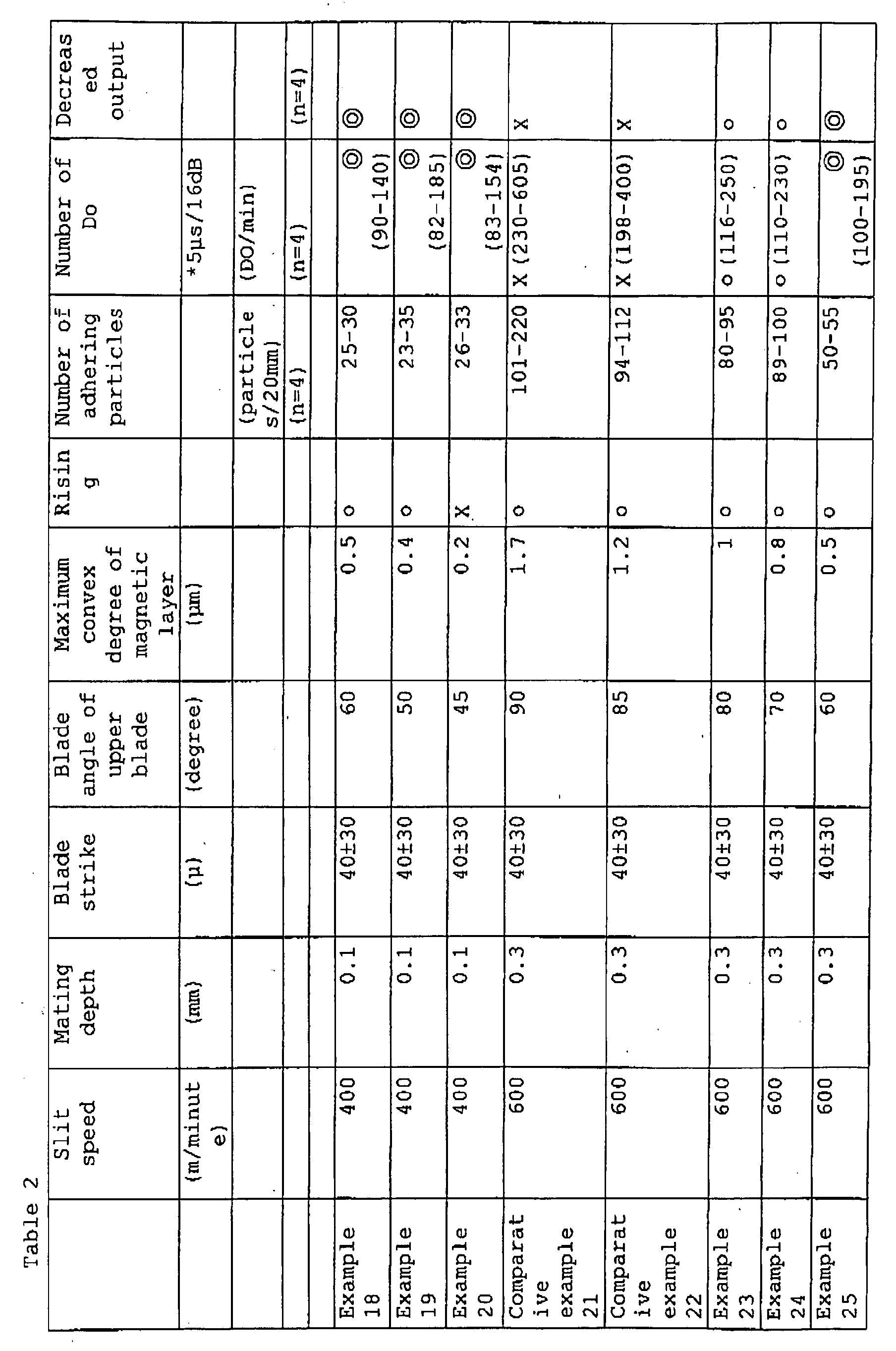
The thus obtained magnetic tape was checked for the maximum
convex degree of the magnetic layer on the non-restraint side
cut surface and the number of adhering particles on the restraint
side cut surface and the non-restraint side cut surface. The
tape was also checked for the number of dropouts and decreased
output. Further, the tape was checked for the rising on the
non-restraint side cut surface. The results are shown in Table
1 and 2, together with other slit conditions.
The maximum convex degree of the magnetic layer was measured
by using a laser microscope (made by JEOL Ltd.).
The number of adhering particles was counted based on a
photograph taken under magnification of 1000 to 2000 times by
using a scanning electric microscope (SEM). Determination was
made at 4 sites (n=4) to count the mean number of adhering
particles.
The running durability was tested, more particularly, a
Sony-made β cam SP-VTR (BVW-75 model) was used at a temperature
of 20°C and RH of 50% to test a 670m-long tape, namely, the tape
portion obtained 5th part running to 85th part running was
reciprocated 100 times by the mode of FF/REW running to determine
the number of dropouts at the drifted site at the time of 5th
part and at the time of 85th part as well as the level of decreased
output. In Table 1 and 2, o ○ denotes 0.5dB or lower in decreased
output, ○ denotes 0.6 to 1.0 dB, Δ denotes 1.1 to 2.0dB and
x denotes 2.1dB or greater.
In determination of the rising on the non-restraint side
cut surface, ○ denotes that a tape slit 4500 to 8000m is reeled
up by a reel hub of 4.5 inch in the outer diameter, without any
abnormal appearance such as radiation on the surface, x denotes
that the tape can not be reeled up due to the rising at the length
of 4500m or more, or if the tape is reeled up, a part or a whole
of the tape is not commercially available due to the development
of radiation, etc.
According to the results of Tables 1 and 2, a magnetic tape
having the maximum convex degree of the magnetic layer on the
non-restraint side cut surface of 1.0µm or lower and a total
number of adhering particles of 100 particles/20mm or lower
exerted an excellent running durability.
This application is based on Japanese Patent application
JP 2004-152855, filed May 24, 2004, the entire content of which
is hereby incorporated by reference. This claim for priority
benefit is being filed concurrently with the filing of this
application.