EP1600636B1 - Progressing cavity pump or motor - Google Patents
Progressing cavity pump or motor Download PDFInfo
- Publication number
- EP1600636B1 EP1600636B1 EP05010488.4A EP05010488A EP1600636B1 EP 1600636 B1 EP1600636 B1 EP 1600636B1 EP 05010488 A EP05010488 A EP 05010488A EP 1600636 B1 EP1600636 B1 EP 1600636B1
- Authority
- EP
- European Patent Office
- Prior art keywords
- stator
- outer tube
- annular seal
- tube
- motor
- Prior art date
- Legal status (The legal status is an assumption and is not a legal conclusion. Google has not performed a legal analysis and makes no representation as to the accuracy of the status listed.)
- Not-in-force
Links
Images


Classifications
-
- F—MECHANICAL ENGINEERING; LIGHTING; HEATING; WEAPONS; BLASTING
- F04—POSITIVE - DISPLACEMENT MACHINES FOR LIQUIDS; PUMPS FOR LIQUIDS OR ELASTIC FLUIDS
- F04C—ROTARY-PISTON, OR OSCILLATING-PISTON, POSITIVE-DISPLACEMENT MACHINES FOR LIQUIDS; ROTARY-PISTON, OR OSCILLATING-PISTON, POSITIVE-DISPLACEMENT PUMPS
- F04C2/00—Rotary-piston machines or pumps
- F04C2/08—Rotary-piston machines or pumps of intermeshing-engagement type, i.e. with engagement of co-operating members similar to that of toothed gearing
- F04C2/10—Rotary-piston machines or pumps of intermeshing-engagement type, i.e. with engagement of co-operating members similar to that of toothed gearing of internal-axis type with the outer member having more teeth or tooth-equivalents, e.g. rollers, than the inner member
- F04C2/107—Rotary-piston machines or pumps of intermeshing-engagement type, i.e. with engagement of co-operating members similar to that of toothed gearing of internal-axis type with the outer member having more teeth or tooth-equivalents, e.g. rollers, than the inner member with helical teeth
- F04C2/1071—Rotary-piston machines or pumps of intermeshing-engagement type, i.e. with engagement of co-operating members similar to that of toothed gearing of internal-axis type with the outer member having more teeth or tooth-equivalents, e.g. rollers, than the inner member with helical teeth the inner and outer member having a different number of threads and one of the two being made of elastic materials, e.g. Moineau type
- F04C2/1073—Rotary-piston machines or pumps of intermeshing-engagement type, i.e. with engagement of co-operating members similar to that of toothed gearing of internal-axis type with the outer member having more teeth or tooth-equivalents, e.g. rollers, than the inner member with helical teeth the inner and outer member having a different number of threads and one of the two being made of elastic materials, e.g. Moineau type where one member is stationary while the other member rotates and orbits
- F04C2/1075—Construction of the stationary member
-
- F—MECHANICAL ENGINEERING; LIGHTING; HEATING; WEAPONS; BLASTING
- F04—POSITIVE - DISPLACEMENT MACHINES FOR LIQUIDS; PUMPS FOR LIQUIDS OR ELASTIC FLUIDS
- F04C—ROTARY-PISTON, OR OSCILLATING-PISTON, POSITIVE-DISPLACEMENT MACHINES FOR LIQUIDS; ROTARY-PISTON, OR OSCILLATING-PISTON, POSITIVE-DISPLACEMENT PUMPS
- F04C15/00—Component parts, details or accessories of machines, pumps or pumping installations, not provided for in groups F04C2/00 - F04C14/00
- F04C15/0003—Sealing arrangements in rotary-piston machines or pumps
- F04C15/0007—Radial sealings for working fluid
- F04C15/0019—Radial sealing elements specially adapted for intermeshing-engagement type machines or pumps, e.g. gear machines or pumps
-
- B—PERFORMING OPERATIONS; TRANSPORTING
- B29—WORKING OF PLASTICS; WORKING OF SUBSTANCES IN A PLASTIC STATE IN GENERAL
- B29C—SHAPING OR JOINING OF PLASTICS; SHAPING OF MATERIAL IN A PLASTIC STATE, NOT OTHERWISE PROVIDED FOR; AFTER-TREATMENT OF THE SHAPED PRODUCTS, e.g. REPAIRING
- B29C45/00—Injection moulding, i.e. forcing the required volume of moulding material through a nozzle into a closed mould; Apparatus therefor
- B29C45/14—Injection moulding, i.e. forcing the required volume of moulding material through a nozzle into a closed mould; Apparatus therefor incorporating preformed parts or layers, e.g. injection moulding around inserts or for coating articles
- B29C45/14631—Coating reinforcements
-
- F—MECHANICAL ENGINEERING; LIGHTING; HEATING; WEAPONS; BLASTING
- F04—POSITIVE - DISPLACEMENT MACHINES FOR LIQUIDS; PUMPS FOR LIQUIDS OR ELASTIC FLUIDS
- F04C—ROTARY-PISTON, OR OSCILLATING-PISTON, POSITIVE-DISPLACEMENT MACHINES FOR LIQUIDS; ROTARY-PISTON, OR OSCILLATING-PISTON, POSITIVE-DISPLACEMENT PUMPS
- F04C15/00—Component parts, details or accessories of machines, pumps or pumping installations, not provided for in groups F04C2/00 - F04C14/00
- F04C15/0003—Sealing arrangements in rotary-piston machines or pumps
-
- F—MECHANICAL ENGINEERING; LIGHTING; HEATING; WEAPONS; BLASTING
- F04—POSITIVE - DISPLACEMENT MACHINES FOR LIQUIDS; PUMPS FOR LIQUIDS OR ELASTIC FLUIDS
- F04D—NON-POSITIVE-DISPLACEMENT PUMPS
- F04D29/00—Details, component parts, or accessories
Definitions
- the present invention relates to a progressing cavity pump or motor. More particularly, this invention relates to an improved techniques for mechanically connecting the elastomeric stator with the outer tube or housing of the pump or motor.
- the typical assembly consists of a rigid rotor which resembles a screw having multiple leads.
- the rotor mates with a stator which has one additional lead cut on the interior of the stator.
- the differences in the leads form cavities between the rotor and the stator. These cavities continually progress from one end of the stator to the other when the rotor is turned. Operation of the pump is achieved by mechanically turning the rotor, while operation as a motor is achieved by forcing fluid into the end cavity to turn the rotor.
- a stator is conventionally an elastomeric or plastic material which is formed by injection molding into the outer sleeve-shaped tube or housing.
- the elastomeric or plastic material is conventionally bonded with the tube, typically with an adhesive for a polymeric stator, and by welding for a metal stator insert. The bond provides a fluid seal between the stator material and the outer tube or housing.
- stator inserts are substantially limited in progressing cavity pumps and motors.
- the use of an adhesive for bonding the plastic or elastomeric material of a stator to the outer housing limits the use of the stator to an operational temperature and chemical environment required by the adhesive. Accordingly, the use of progressing cavity pumps and motors with a plastic or elastomeric stator has heretofore been limited.
- WO 2005/047702 discloses an eccentric screw pump or worm motor with an outer tube and two inner tubes, the inner tubes having a plurality of through apertures, and a rotor for rotating within the stator.
- a lining material is molded within the outer tube, and a sealing ring 10, 20 is secured to the outer tube, axially spaced from the inner tubes, to provide a seal between the lining material and the outer tube.
- WO 2005/047701 discloses a very similar stator for an eccentric screw pump or worm motor, but with only one inner tube and without the sealing ring.
- this stator the inner tube is welded to the outer tube, and metallic spacers are provided to separate the inner and outer tubes.
- DE 2250263 discloses a method of securing a molded stator material within an outer tube or housing of a progressing cavity pump or motor comprising injecting stator material into one of the outer tube and the housing, through a plurality of apertures, such that the stator material fills the apertures and a space radially outward of the apertures.
- the present invention seeks to provide an improved progressing cavity pump or motor.
- a progressing cavity pump or motor comprising: an outer sleeve-shaped tube; a stator material molded within the outer tube; a rotor for rotating within the stator; an inner tube spaced radially between an outer surface of the stator and an inner surface of the stator, the inner tube including a plurality of through apertures each filled with stator material, and one or more annular seal glands each positioned between an inner surface of the outer tube and an outer surface of the inner tube for sealing the stator material to the outer tube wherein each of the one or more annular seal glands (18) includes an axially extending lip (26) spaced radially from the outer tube (12), such that the stator material (20) seals between the annular seal gland (18) and the outer tube (12).
- each of the one or more annular seal glands is secured to each of the outer tube and the inner tube by welding.
- stator material fills in a gap between the lip and the outer tube.
- one or more annular seal glands comprise a pair of annular seal glands, each annular seal gland positioned adjacent on end of the inner tube, and each axially extending lip extending toward a center portion of the inner tube.
- one or more annular seal glands comprise one or more intermediate annular seal glands spaced between the pair of annular seal glands adjacent the ends of the inner tube.
- stator material at least substantially fills a gap between an inner surface of the outer tube and an outer surface of the inner tube.
- the plurality of through apertures are spaced in axially extending rows and circumferentially spaced columns.
- stator is a polymeric or elastomeric plastic material installed in the outer tube by an injection molding process.
- a radially outer surface of the stator material is recessed relative to an outer surface of the outer tube.
- One embodiment of the cavity pump or motor further comprises one or more annular seal glands each fixed to the outer tube for sealing between the housing and the stator material.
- each of the one or more annular seal glands includes an axially extending lip, such that the stator material fills in the gap between the lip and the housing and seals with the housing.
- the one or more annular seal glands comprise a pair of annular seal glands, each annular seal gland positioned adjacent on end of the housing, and each axially extending lip extending toward a center portion of the housing.
- a method of securing a molded stator material within an outer tube or housing of a progressing cavity pump or motor including a rotor for rotating within the stator comprising: spacing an inner tube radially within the outer tube; positioning one or more annular seal glands between an outer surface of the inner tube and an inner surface of the outer tube adjacent an end of the inner tube, wherein each of the one or more annular seal glands includes an axially extending lip spaced radially from the outer tube; providing a plurality of apertures in the one of the inner tube; and injecting the stator material into the one of the outer tube and the housing and through the plurality of apertures, such that the stator material fills the apertures and a space radially outward of the apertures, and such that for each of the one or more annular seal glands, the stator material seals between the annular seal gland and the outer tube.
- the method further comprises: securing one or more annular seal glands to one of the inner tube and the housing each for sealing between the stator material and one of the outer tube and the housing.
- the method further comprises: providing the plurality of apertures in axially extending rows and circumferentially spaced columns.
- a further example of the invention comprises a progressing cavity pump or motor, comprising: an outer housing; a stator material molded within the outer housing; a rotor for rotating within the stator; and two or more annular seal glands each fixed to the housing for sealing between the housing and the stator material.
- each of the two or more annular seal glands includes an axially extending lip, such that the stator material fills in the gap between each lip and the housing and seals with the housing.
- each annular seal gland is positioned adjacent an end of the housing, and each axially extending lip extends toward a center portion of the housing.
- the preferred progressing cavity pump or motor provides a mechanical connection of the stator material and the outer tube or housing, thereby eliminating the need for an adhesive. By eliminating the need for an adhesive, the operational uses of the progressing cavity pump and motor are substantially expanded.
- a progressing pump or motor comprises an outer sleeve-shaped tube, a stator within the outer tube, and a rotor for rotating within the stator.
- An inner tube is spaced radially between an outer surface of the stator and the inner surface of the stator, with the inner tube including a plurality of apertures each filled with stator material.
- One or more annular seal glands may be secured to an inner surface of the outer tube and an outer surface of the inner tube to position the outer tube in its desired location when the stator material is installed, and to seal the stator to the outer tube.
- a progressing cavity pump or motor comprises an outer housing, a stator molded within the outer housing and a rotor for rotating the stator.
- a plurality of annular seal glands are each fixed to the housing for sealing between the housing and the stator material.
- Each annular seal gland may include an axially extending lip, such that the stator material fills the gap between the lip and the housing and seals with the housing.
- the lip of each annular seal gland may be axially extending toward a center portion of the housing.
- the stator material may be installed in the outer tube or housing by a molding process.
- Each of the one or more annular seal glands may be secured to the outer tube and the inner tube by welding.
- Each of the annular seal glands preferably includes an axial extending lip, such that the stator material fills the gap between the lip and the outer tube or housing and seals between the annular seal gland and the outer tube or housing.
- a pair of seal glands may be provided, each positioned adjacent an end of the inner tube or the ends of the one or more grooves, with each axially extending lip extending toward a center portion of the outer tube or housing.
- One or more intermediate annular seal glands may also be provided between the pair of annular seal glands.
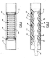
- Figure 1 discloses a progressing cavity pump or motor 10 having an outer sleeve-shaped tube 12 and an inner tube 14 spaced radially within the outer tube.
- the inner tube 14 includes a plurality of apertures 16, which may comprise a regular pattern of rows and columns as shown in Figure 1 .
- a pair of annular seal glands 18 are each secured to the outer surface of the inner tube and the inner surface of the outer tube, and position the inner tube when the elastomeric material of the stator is installed. Annular seal glands may be fixed at the desired locations along the axial length of the inner tube as needed to provide proper structural support. As explained subsequently, the annular seal glands provide a fluid seal between the stator and the outer tube.
- the outer tube 10 and the housing discussed subsequently are conventionally threaded at the outer surface of their ends for attachment to conventional tubulars or other downhole tools.
- the material, for the stator 20 is conventionally molded into the outer tube 12.
- the stator material is thus forced radially outward by pressure through the apertures 22 in the inner tube, and also into the annular space 24 between the inner tube and the outer tube.
- Stator material thus at least substantially fills the gap between the outer surface of tube 14 and the inner surface of tube 12.
- the stator material is forced into the annular gap between each annular seal gland and the outer tube.
- the injected stator material may be a thermo- plastic, a plastic or a metal material which is injected under high pressure into the outer tube 12.
- the inner tube 14 thus has sufficient structural integrity to withstand the high pressure involved in injecting the stator material into the tube 12.
- Figure 2 also depicts a short section of a rotor 90 for positioning within the stator.
- each of the one or more annular seal glands 18 may include an axially extending lip 26 spaced radially from the outer tube 12 and extending axially from ring body 28, such that the stator material fills the annular gap between the lip and the outer tube and seals between the annular seal gland and the outer tube.
- a pair of annular seal glands may be provided adjacent to the ends of the inner tube, and each axially extending lip extends toward a center portion of the outer tube 12. Additional annular seal glands may be spaced between the pair of annular seal glands to provide added support, as shown in Figure 2 .
- Figure 3 shows a weld 30 between the outer tube and the annular seal gland, and another weld 32 between the annular seal gland and the end of the inner tube.
- the axially extending lip 26 provides an end section 34 which is radially thicker than a central section 33, thereby forming an annular recess radially outward of central section 33 for receiving stator material,
- Each sealing ring provides for low pressure sealing of the elastomeric stator 20 with the outer sleeve 12. If the molded material shrinks due to curing, temperature change or chemical exposure, then a fluid seal is created with the radially exterior faces 42 and 44. If the molded expands, a fluid seal is formed with the radially interior faces 46, 48, 50 and 52. Sealing at high pressure is accomplished by the interior fluid pressure compressing the molded material against the interior faces. Whether under low pressure or high pressure, a reliable fluid tight seal is formed between the stator and the outer tube 12.
- the inner tube 14 provides substantial mechanical support for the material of the stator 20 during use of the pump or motor 10. More particularly, the overall shape of the stator material is desirably maintained by the mechanical connection between the inner tube 14 and the stator material, which flows through the apertures and into the annular space 24 between the inner tube 14 and the outer tube 12. A radially outward portion of the stator material is thus mechanically connected or locked to the inner tube, and the stator material near the ends of the inner tube are effectively sealed to the outer tube 12 by the annular seal glands 18.
- the radial outer surface of the inner tube may be spaced from 4.7 mm (3/16 inch) to 7.9 mm (5/16 inch) from the outer surface of the outer tube, thereby providing a substantial space 24 for receiving stator material which flows through the apertures 22 in the inner tube.
- the through apertures 16, as shown in Figure 1 may be spaced in an axially extending rows and circumferentially spaced columns.
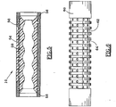
- an outer housing of a progressing cavity pump or motor is provided with one or more grooves in an outer surface of the outer housing, with the groove or grooves having an outer surface radius less than the outer housing surface radius.
- a plurality of axially extending grooves 52 each have the plurality of through apertures 54 therein, such that the grooves are each in fluid communication with a plurality of apertures.
- the cutting of the grooves in the outer housing 50 thus allows stator material to both flow through the apertures 54, and to fill the gap radially outwardly of the reduced thickness housing formed by the grooves.
- Each of the grooves could have a groove axis generally parallel to the housing axis, or the grooves could be both axially extending and spiraling about the housing.
- Figure 5 shows a pair of annular seal glands provided at each end of the housing 50.
- the annular seal glands are integral with the housing 50, but otherwise serve the same function of assuring a reliable seal between the elastomeric material 20 and the outer housing 50.
- the ring body is now part of the outer housing 50, and the lips 56 of the annular seal glands preferably are directed toward a center portion of housing 50.
- Figure 6 shows an outer housing 60 for a progressing cavity pump or motor, with a plurality of circumferential grooves 62 spaced along a substantial axial length of the housing 60, and a plurality of through apertures 64 provided in each of the circumferential grooves.
- Figure 7 shows the same housing with an stator material filling the apertures 64 and forming exterior rings of stator material about the outer housing. Annular seal glands are provided at each end of the housing.
- the circumferential grooves could each have a groove axis perpendicular to the housing axis, or the groove or grooves could be circumferential grooves which spiral down the length of the housing.
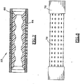
- Figure 8 shows another embodiment of outer housing 70 with a plurality of apertures 72 arranged in axially extending rows and circumferentially extending columns.
- This design thus incorporates a substantially elongate and continuous circumferential groove rather than a plurality of grooves cut in the outer surface of the housing 70.
- a tube with a plurality of apertures may be welded or otherwise secured to a pair of housing end members having a slightly larger diameter than the tube, thereby avoiding the expense of cutting the groove in the outer housing.
- Figure 9 shows the housing 70 filled with stator material, and also depicts a pair of annular seal glands adjacent to the end of the housing 70.
- Stator material flows through the ports 72 and occupies the space between the outer surface of the reduced radius groove and the outer surface of the outer housing, thereby effectively forming an stator material sleeve 76 radially outward of the apertures 72.
- a sleeve of the mold may be provided over the outer housing for the embodiments as shown in Figure 4-9 to contain the stator material, so that the stator material does not migrate radially outward from an outer surface of the housing during the molding process.
- the stator material may thus be flush with the outer surface of the housing, but may also be slightly recessed with respect to the outer surface of the housing to better protect the stator material when the pump or motor is placed downhole.
- the stator material may be recessed with respect to the outer surface of the housing as shown in Figures 5 , 7 and 9 a radial spacing of approximately 3.2 mm (1/8 inch) or slightly more to protect the stator material.
- a plastic treated metal or fabric weave material may be bonded to the radially outer surface of the stator material to add strength and reduce stator deterioration when placed downhole.
- various slats, rings, and other members may be used to cover over the exposed stator material to better protect the stator material when it is placed downhole.
- apertures disclosed herein may each have a circular cross section as shown, but may have other cross sections, including oval, slotted, or rectangular apertures. More particularly, an oval or slotted shape allows orientation of the apertures with the directional forces imparting to the molded material. Apertures also need not have a uniform cross-section along their radial length, and instead may be tapered or otherwise configured to accomplish the purposes set forth therein.
- the combination of the reduced radius groove or grooves in the outer surface of the housing and the apertures in fluid communication with the grooves provides the desired mechanical support for the stator material, while the material is sealed to the ends of the housing by the annular seal glands.
- the stator material thus flows through and radially outward of the apertures, and when cured provides a substantial mechanical bound between the outer tube and the stator material, so that no adhesive for bonding the stator material to the outer housing is required.
- stator The selected material for the stator will largely depend upon the intended application for the downhole pump and motor.
- an elastomeric material stator may be suitable.
- a high strength plastic or polymeric material stator would be required.
- Polymeric and elastomeric materials include various types of rubbers and plastics, including reinforced rubber and plastic materials.
- a cast metal stator may be desired to withstand the high operating temperatures.
- the stator is injected under high pressure into the outer tube or housing, with the outer tube or tubular housing serving as a partial mold for the injected material.
- annular seal gland as shown in Figure 3 may be conventionally formed by a machining operation, and welded or otherwise secured to both the outer tube 12 and the inner tube 14, as discussed above.
- one or more components of the annular seal gland may be separately manufactured from the outer housing, then welded or otherwise secured in placed to produce the desired configuration as shown in the drawings.
- the progressing cavity pump or motor has been discussed in detail above with respect to the features for mechanically bonding the stator material to the outer tube or the housing.
- the apertures in the inner tube or in a portion of the housing wall are convenient for mechanically connecting the stator material to the outer tube or the housing, other techniques may be used to mechanically connect the stator material to the housing, such as ribs or rails on the inside of the housing.
- a particular feature of the invention is the ability to reliably seal between the outer housing and the stator material utilizing a one or more annular seal glands as disclosed herein. Regardless of the technique used to mechanically connect the stator material to the housing, two or more stator rings may thus be reliably used to seal the stator material to the outer housing.
- a number of annular seal glands may be provided along the length of the housing, and may also serve to mechanically connect the stator material to the outer housing.
Description
- The present invention relates to a progressing cavity pump or motor. More particularly, this invention relates to an improved techniques for mechanically connecting the elastomeric stator with the outer tube or housing of the pump or motor.
- Progressing cavity pumps and motors have been used for decades in pumping and hydraulic motor applications. The typical assembly consists of a rigid rotor which resembles a screw having multiple leads. The rotor mates with a stator which has one additional lead cut on the interior of the stator. The differences in the leads form cavities between the rotor and the stator. These cavities continually progress from one end of the stator to the other when the rotor is turned. Operation of the pump is achieved by mechanically turning the rotor, while operation as a motor is achieved by forcing fluid into the end cavity to turn the rotor.
- A stator is conventionally an elastomeric or plastic material which is formed by injection molding into the outer sleeve-shaped tube or housing. The elastomeric or plastic material is conventionally bonded with the tube, typically with an adhesive for a polymeric stator, and by welding for a metal stator insert. The bond provides a fluid seal between the stator material and the outer tube or housing.
- The use of metal stator inserts is substantially limited in progressing cavity pumps and motors. The use of an adhesive for bonding the plastic or elastomeric material of a stator to the outer housing limits the use of the stator to an operational temperature and chemical environment required by the adhesive. Accordingly, the use of progressing cavity pumps and motors with a plastic or elastomeric stator has heretofore been limited.
-
WO 2005/047702 discloses an eccentric screw pump or worm motor with an outer tube and two inner tubes, the inner tubes having a plurality of through apertures, and a rotor for rotating within the stator. A lining material is molded within the outer tube, and asealing ring -
WO 2005/047701 discloses a very similar stator for an eccentric screw pump or worm motor, but with only one inner tube and without the sealing ring. In this stator the inner tube is welded to the outer tube, and metallic spacers are provided to separate the inner and outer tubes. -
DE 2250263 discloses a method of securing a molded stator material within an outer tube or housing of a progressing cavity pump or motor comprising injecting stator material into one of the outer tube and the housing, through a plurality of apertures, such that the stator material fills the apertures and a space radially outward of the apertures. - The present invention seeks to provide an improved progressing cavity pump or motor.
- According to one aspect of this invention there is provided a progressing cavity pump or motor, comprising: an outer sleeve-shaped tube; a stator material molded within the outer tube; a rotor for rotating within the stator; an inner tube spaced radially between an outer surface of the stator and an inner surface of the stator, the inner tube including a plurality of through apertures each filled with stator material, and one or more annular seal glands each positioned between an inner surface of the outer tube and an outer surface of the inner tube for sealing the stator material to the outer tube wherein each of the one or more annular seal glands (18) includes an axially extending lip (26) spaced radially from the outer tube (12), such that the stator material (20) seals between the annular seal gland (18) and the outer tube (12).
- Preferably each of the one or more annular seal glands is secured to each of the outer tube and the inner tube by welding.
- Advantageously, the stator material fills in a gap between the lip and the outer tube.
- Conveniently one or more annular seal glands comprise a pair of annular seal glands, each annular seal gland positioned adjacent on end of the inner tube, and each axially extending lip extending toward a center portion of the inner tube.
- Preferably one or more annular seal glands comprise one or more intermediate annular seal glands spaced between the pair of annular seal glands adjacent the ends of the inner tube.
- Advantageously the stator material at least substantially fills a gap between an inner surface of the outer tube and an outer surface of the inner tube.
- Conveniently the plurality of through apertures are spaced in axially extending rows and circumferentially spaced columns.
- Advantageously the stator is a polymeric or elastomeric plastic material installed in the outer tube by an injection molding process.
- Conveniently a radially outer surface of the stator material is recessed relative to an outer surface of the outer tube.
- One embodiment of the cavity pump or motor further comprises one or more annular seal glands each fixed to the outer tube for sealing between the housing and the stator material.
- Preferably each of the one or more annular seal glands includes an axially extending lip, such that the stator material fills in the gap between the lip and the housing and seals with the housing.
- Conveniently the one or more annular seal glands comprise a pair of annular seal glands, each annular seal gland positioned adjacent on end of the housing, and each axially extending lip extending toward a center portion of the housing.
- According to another aspect of this invention there is provided a method of securing a molded stator material within an outer tube or housing of a progressing cavity pump or motor including a rotor for rotating within the stator, a method comprising: spacing an inner tube radially within the outer tube; positioning one or more annular seal glands between an outer surface of the inner tube and an inner surface of the outer tube adjacent an end of the inner tube, wherein each of the one or more annular seal glands includes an axially extending lip spaced radially from the outer tube; providing a plurality of apertures in the one of the inner tube; and injecting the stator material into the one of the outer tube and the housing and through the plurality of apertures, such that the stator material fills the apertures and a space radially outward of the apertures, and such that for each of the one or more annular seal glands, the stator material seals between the annular seal gland and the outer tube.
- Preferably the method further comprises: securing one or more annular seal glands to one of the inner tube and the housing each for sealing between the stator material and one of the outer tube and the housing.
- Advantageously the method further comprises: providing the plurality of apertures in axially extending rows and circumferentially spaced columns.
- A further example of the invention comprises a progressing cavity pump or motor, comprising: an outer housing; a stator material molded within the outer housing; a rotor for rotating within the stator; and two or more annular seal glands each fixed to the housing for sealing between the housing and the stator material.
- Conveniently each of the two or more annular seal glands includes an axially extending lip, such that the stator material fills in the gap between each lip and the housing and seals with the housing.
- Preferably each annular seal gland is positioned adjacent an end of the housing, and each axially extending lip extends toward a center portion of the housing.
- The preferred progressing cavity pump or motor provides a mechanical connection of the stator material and the outer tube or housing, thereby eliminating the need for an adhesive. By eliminating the need for an adhesive, the operational uses of the progressing cavity pump and motor are substantially expanded.
- In one embodiment, a progressing pump or motor comprises an outer sleeve-shaped tube, a stator within the outer tube, and a rotor for rotating within the stator. An inner tube is spaced radially between an outer surface of the stator and the inner surface of the stator, with the inner tube including a plurality of apertures each filled with stator material. One or more annular seal glands may be secured to an inner surface of the outer tube and an outer surface of the inner tube to position the outer tube in its desired location when the stator material is installed, and to seal the stator to the outer tube.
- In yet another embodiment, a progressing cavity pump or motor comprises an outer housing, a stator molded within the outer housing and a rotor for rotating the stator. A plurality of annular seal glands are each fixed to the housing for sealing between the housing and the stator material. Each annular seal gland may include an axially extending lip, such that the stator material fills the gap between the lip and the housing and seals with the housing. The lip of each annular seal gland may be axially extending toward a center portion of the housing.
- The stator material may be installed in the outer tube or housing by a molding process.
- Each of the one or more annular seal glands may be secured to the outer tube and the inner tube by welding.
- Each of the annular seal glands preferably includes an axial extending lip, such that the stator material fills the gap between the lip and the outer tube or housing and seals between the annular seal gland and the outer tube or housing. A pair of seal glands may be provided, each positioned adjacent an end of the inner tube or the ends of the one or more grooves, with each axially extending lip extending toward a center portion of the outer tube or housing. One or more intermediate annular seal glands may also be provided between the pair of annular seal glands.
- These and further features and advantages of the present invention will become apparent from the following detailed description, which is given by way of example and wherein reference is made to the figures in the accompanying drawings, in which:.
-
Figure 1 is the side view of an outer tube of a progressing cavity pump or motor and an inner tube positioned within the outer tube, -
Figure 2 is a cross sectional view of pump and motor components similar to those shown inFigure 1 , with a stator injection molded in the outer tube, and a portion of a rotor for positioning in the stator, -
Figure 3 is a detailed cross sectional view of a annular seal gland between the outer tube and the inner tube, -
Figure 4 is a side view of an outer housing of a progressing cavity pump or motor with elongate axially extending slots, -
Figure 5 is a cross sectional view of the pump and motor components shown inFigure 4 , with a stator injection motor within the housing, -
Figure 6 is a side view of an alternative outer tube of a progressing cavity pump or motor with a plurality of axially spaced circumferential grooves in the outer tube, -
Figure 7 is a cross sectional view of the pump and motor components as shown inFigure 6 , with a stator injection molded in the outer housing, -
Figure 8 is a side view of an outer tube of a progressing cavity pump or motor with an elongate circumferential slot in the outer tube, and -
Figure 9 is a cross sectional view of the pump and motor components as shown inFigure 8 , with a stator injection molded in the outer housing. -
Figure 1 discloses a progressing cavity pump ormotor 10 having an outer sleeve-shaped tube 12 and aninner tube 14 spaced radially within the outer tube. Theinner tube 14 includes a plurality ofapertures 16, which may comprise a regular pattern of rows and columns as shown inFigure 1 . A pair ofannular seal glands 18 are each secured to the outer surface of the inner tube and the inner surface of the outer tube, and position the inner tube when the elastomeric material of the stator is installed. Annular seal glands may be fixed at the desired locations along the axial length of the inner tube as needed to provide proper structural support. As explained subsequently, the annular seal glands provide a fluid seal between the stator and the outer tube. Although not shown in the figures, those skilled in the art will appreciate that theouter tube 10 and the housing discussed subsequently are conventionally threaded at the outer surface of their ends for attachment to conventional tubulars or other downhole tools. - Referring to
Figure 2 , the material, for thestator 20 is conventionally molded into theouter tube 12. The stator material is thus forced radially outward by pressure through theapertures 22 in the inner tube, and also into theannular space 24 between the inner tube and the outer tube. Stator material thus at least substantially fills the gap between the outer surface oftube 14 and the inner surface oftube 12. Finally, the stator material is forced into the annular gap between each annular seal gland and the outer tube. The injected stator material may be a thermo- plastic, a plastic or a metal material which is injected under high pressure into theouter tube 12. Theinner tube 14 thus has sufficient structural integrity to withstand the high pressure involved in injecting the stator material into thetube 12.Figure 2 also depicts a short section of arotor 90 for positioning within the stator. - Referring to
Figure 3 , each of the one or moreannular seal glands 18 may include anaxially extending lip 26 spaced radially from theouter tube 12 and extending axially fromring body 28, such that the stator material fills the annular gap between the lip and the outer tube and seals between the annular seal gland and the outer tube. A pair of annular seal glands may be provided adjacent to the ends of the inner tube, and each axially extending lip extends toward a center portion of theouter tube 12. Additional annular seal glands may be spaced between the pair of annular seal glands to provide added support, as shown inFigure 2 .Figure 3 shows aweld 30 between the outer tube and the annular seal gland, and anotherweld 32 between the annular seal gland and the end of the inner tube. - In a preferred embodiment of the annular seal gland, the
axially extending lip 26 provides anend section 34 which is radially thicker than acentral section 33, thereby forming an annular recess radially outward ofcentral section 33 for receiving stator material, Each sealing ring provides for low pressure sealing of theelastomeric stator 20 with theouter sleeve 12. If the molded material shrinks due to curing, temperature change or chemical exposure, then a fluid seal is created with the radially exterior faces 42 and 44. If the molded expands, a fluid seal is formed with the radially interior faces 46, 48, 50 and 52. Sealing at high pressure is accomplished by the interior fluid pressure compressing the molded material against the interior faces. Whether under low pressure or high pressure, a reliable fluid tight seal is formed between the stator and theouter tube 12. - The
inner tube 14 provides substantial mechanical support for the material of thestator 20 during use of the pump ormotor 10. More particularly, the overall shape of the stator material is desirably maintained by the mechanical connection between theinner tube 14 and the stator material, which flows through the apertures and into theannular space 24 between theinner tube 14 and theouter tube 12. A radially outward portion of the stator material is thus mechanically connected or locked to the inner tube, and the stator material near the ends of the inner tube are effectively sealed to theouter tube 12 by theannular seal glands 18. - In one embodiment, the radial outer surface of the inner tube may be spaced from 4.7 mm (3/16 inch) to 7.9 mm (5/16 inch) from the outer surface of the outer tube, thereby providing a
substantial space 24 for receiving stator material which flows through theapertures 22 in the inner tube. The throughapertures 16, as shown inFigure 1 , may be spaced in an axially extending rows and circumferentially spaced columns. - In another design, not in accordance with the invention, an outer housing of a progressing cavity pump or motor is provided with one or more grooves in an outer surface of the outer housing, with the groove or grooves having an outer surface radius less than the outer housing surface radius.
- In
Figure 4 , a plurality of axially extendinggrooves 52 each have the plurality of throughapertures 54 therein, such that the grooves are each in fluid communication with a plurality of apertures. The cutting of the grooves in theouter housing 50 thus allows stator material to both flow through theapertures 54, and to fill the gap radially outwardly of the reduced thickness housing formed by the grooves. Each of the grooves could have a groove axis generally parallel to the housing axis, or the grooves could be both axially extending and spiraling about the housing.Figure 5 shows a pair of annular seal glands provided at each end of thehousing 50. The annular seal glands are integral with thehousing 50, but otherwise serve the same function of assuring a reliable seal between theelastomeric material 20 and theouter housing 50. The ring body is now part of theouter housing 50, and thelips 56 of the annular seal glands preferably are directed toward a center portion ofhousing 50. -
Figure 6 shows anouter housing 60 for a progressing cavity pump or motor, with a plurality ofcircumferential grooves 62 spaced along a substantial axial length of thehousing 60, and a plurality of throughapertures 64 provided in each of the circumferential grooves.Figure 7 shows the same housing with an stator material filling theapertures 64 and forming exterior rings of stator material about the outer housing. Annular seal glands are provided at each end of the housing. The circumferential grooves could each have a groove axis perpendicular to the housing axis, or the groove or grooves could be circumferential grooves which spiral down the length of the housing. -
Figure 8 shows another embodiment ofouter housing 70 with a plurality ofapertures 72 arranged in axially extending rows and circumferentially extending columns. This design thus incorporates a substantially elongate and continuous circumferential groove rather than a plurality of grooves cut in the outer surface of thehousing 70. In the alternative, a tube with a plurality of apertures may be welded or otherwise secured to a pair of housing end members having a slightly larger diameter than the tube, thereby avoiding the expense of cutting the groove in the outer housing. -
Figure 9 shows thehousing 70 filled with stator material, and also depicts a pair of annular seal glands adjacent to the end of thehousing 70. Stator material flows through theports 72 and occupies the space between the outer surface of the reduced radius groove and the outer surface of the outer housing, thereby effectively forming an stator material sleeve 76 radially outward of theapertures 72. - During the injection molding of the stator, a sleeve of the mold (not shown) may be provided over the outer housing for the embodiments as shown in
Figure 4-9 to contain the stator material, so that the stator material does not migrate radially outward from an outer surface of the housing during the molding process. The stator material may thus be flush with the outer surface of the housing, but may also be slightly recessed with respect to the outer surface of the housing to better protect the stator material when the pump or motor is placed downhole. In preferred embodiments, the stator material may be recessed with respect to the outer surface of the housing as shown inFigures 5 ,7 and9 a radial spacing of approximately 3.2 mm (1/8 inch) or slightly more to protect the stator material. A plastic treated metal or fabric weave material may be bonded to the radially outer surface of the stator material to add strength and reduce stator deterioration when placed downhole. In addition, various slats, rings, and other members may be used to cover over the exposed stator material to better protect the stator material when it is placed downhole. - It should be pointed out that the apertures disclosed herein may each have a circular cross section as shown, but may have other cross sections, including oval, slotted, or rectangular apertures. More particularly, an oval or slotted shape allows orientation of the apertures with the directional forces imparting to the molded material. Apertures also need not have a uniform cross-section along their radial length, and instead may be tapered or otherwise configured to accomplish the purposes set forth therein.
- For each of the embodiments shown in
Figure 5 ,7 and9 , the combination of the reduced radius groove or grooves in the outer surface of the housing and the apertures in fluid communication with the grooves provides the desired mechanical support for the stator material, while the material is sealed to the ends of the housing by the annular seal glands. The stator material thus flows through and radially outward of the apertures, and when cured provides a substantial mechanical bound between the outer tube and the stator material, so that no adhesive for bonding the stator material to the outer housing is required. In other embodiments, it may be desirable to also use an adhesive material between the stator material and the interior surface of the housing at locations which do not have through apertures, e.g., at the ends of the housing. - The selected material for the stator will largely depend upon the intended application for the downhole pump and motor. In some embodiments an elastomeric material stator may be suitable. In other embodiments, a high strength plastic or polymeric material stator would be required. Polymeric and elastomeric materials include various types of rubbers and plastics, including reinforced rubber and plastic materials. In still other embodiments, a cast metal stator may be desired to withstand the high operating temperatures. In each of the embodiments, the stator is injected under high pressure into the outer tube or housing, with the outer tube or tubular housing serving as a partial mold for the injected material.
- An annular seal gland as shown in
Figure 3 may be conventionally formed by a machining operation, and welded or otherwise secured to both theouter tube 12 and theinner tube 14, as discussed above. When providing the annular seal glands in the body of the outer housing, one or more components of the annular seal gland may be separately manufactured from the outer housing, then welded or otherwise secured in placed to produce the desired configuration as shown in the drawings. - The progressing cavity pump or motor has been discussed in detail above with respect to the features for mechanically bonding the stator material to the outer tube or the housing. Although the apertures in the inner tube or in a portion of the housing wall are convenient for mechanically connecting the stator material to the outer tube or the housing, other techniques may be used to mechanically connect the stator material to the housing, such as ribs or rails on the inside of the housing. A particular feature of the invention, however, is the ability to reliably seal between the outer housing and the stator material utilizing a one or more annular seal glands as disclosed herein. Regardless of the technique used to mechanically connect the stator material to the housing, two or more stator rings may thus be reliably used to seal the stator material to the outer housing. In some applications, a number of annular seal glands may be provided along the length of the housing, and may also serve to mechanically connect the stator material to the outer housing.
- When used in this specification and claims, the terms "comprises" and "comprising" and variations thereof mean that the specified features, steps or integers are included. The terms are not to be interpreted to exclude the presence of other features, steps or components.
- The foregoing disclosure and description of the invention is illustrative and explanatory of preferred embodiments. It would be appreciated by those skilled in the art that various changes in the size, shape of materials, as well as in the details of the illustrated construction or combination of features discussed herein may be made without departing from the invention, which is defined by the following claims.
Claims (12)
- A progressing cavity pump or motor (10), comprising:an outer sleeve-shaped tube (12);a stator material (20) molded within the outer tube (12);a rotor (90) for rotating within the stator (20);an inner tube (14) spaced radially between an outer surface of the stator (20) and an inner surface of the stator (20), the inner tube (14) including a plurality of through apertures (16) each filled with stator material (20),characterised in that the pump or motor (10) further comprises;one or more annular seal glands (18) each positioned adjacent an end of the inner tube between an inner surface of the outer tube (12) and an outer surface of the inner tube (14) for sealing the stator material (20) to the outer tube (12)wherein each of the one or more annular seal glands (18) includes an axially extending lip (26) spaced radially from the outer tube (12), such that the stator material (20) seals between the annular seal gland (18) and the outer tube (12).
- A progressing cavity pump or motor (10) as defined in claim 1, wherein the one or more annular seal glands (18) is secured to each of the outer tube (12) and the inner tube (14) by welding.
- A progressing cavity pump or motor (10) as defined in Claim 1 or 2, wherein the stator material (20) fills in a gap between the lip (26) and the outer tube (12).
- A progressing cavity pump or motor (10) as defined in Claim 2 or 3 wherein the one or more annular seal glands (18) comprise a pair of annular seal glands (18), and each axially extending lip (26) extends toward a center portion of the inner tube (14).
- A progressing cavity pump or motor (10) as defined in anyone of the preceding Claims, wherein the plurality of through apertures (16) are spaced in axially extending rows and circumferentially spaced columns.
- A progressing cavity pump or motor (10) as defined in anyone of the preceding Claims, wherein the stator (20) is a polymeric or elastomeric plastic material installed in the outer tube (12) by an injection molding process.
- A progressing cavity pump or motor (10) as defined in any preceding Claim, wherein the one or more annular seal glands (18) comprise one or more intermediate annular seal glands spaced between the pair of annular seal glands (18) adjacent the ends of the inner tube (14).
- A progressing cavity pump or motor (10) as defined in any preceding Claim, further comprising: an end section (34) of each axially extending lip (26) defining an inner face (44) spaced axially between an end face of the axially extending lip (26) and a base of the seal gland (18), the inner face (44) lying substantially within a plane perpendicular to an axis of the outer tube (12).
- A progressing cavity pump or motor (10) as defined in Claim 8, wherein an inner surface (42) of the axially extending lip (26) between the base and the inner face (44) lies within a plane substantially parallel to the axis of the outer tube (12).
- A method of securing a molded stator material (20) within an outer tube (12) or housing of a progressing cavity pump or motor (10) including a rotor (90) for rotating within the stator (20), a method comprising:spacing an inner tube (14) radially within the outer tube (12);positioning one or more annular seal glands (18) between an outer surface of the inner tube (14) and an inner surface of the outer tube (12) adjacent an end of the inner tube (14), wherein each of the one or more annular seal glands (18) includes an axially extending lip (26) spaced radially from the outer tube (12);providing a plurality of apertures (16) in the one of the inner tube (14); andinjecting the stator material (20) into the one of the outer tube (12) and the housing and through the plurality of apertures (16). such that the stator material (20) fills the apertures (16) and a space radially outward of the apertures (16), and such that for each of the one or more annular seal glands (18), the stator material (20) seals between the annular seal gland (18) and the outer tube (12).
- A method as defined in Claim 10, further comprising:securing one or more of the annular seal glands (18) to one of the inner tube (14) and the housing each for sealing between the stator material (20) and one of the outer tube (12) and the housing.
- A method as defined in Claim 10 or 11, further comprising:providing the plurality of apertures (16) in axially extending rows and circumferentially spaced columns.
Applications Claiming Priority (2)
| Application Number | Priority Date | Filing Date | Title |
|---|---|---|---|
| US10/845,951 US7407372B2 (en) | 2004-05-14 | 2004-05-14 | Progressing cavity pump or motor |
| US845951 | 2004-05-14 |
Publications (3)
| Publication Number | Publication Date |
|---|---|
| EP1600636A2 EP1600636A2 (en) | 2005-11-30 |
| EP1600636A3 EP1600636A3 (en) | 2006-07-19 |
| EP1600636B1 true EP1600636B1 (en) | 2017-07-19 |
Family
ID=34936505
Family Applications (1)
| Application Number | Title | Priority Date | Filing Date |
|---|---|---|---|
| EP05010488.4A Not-in-force EP1600636B1 (en) | 2004-05-14 | 2005-05-13 | Progressing cavity pump or motor |
Country Status (5)
| Country | Link |
|---|---|
| US (1) | US7407372B2 (en) |
| EP (1) | EP1600636B1 (en) |
| AR (1) | AR048960A1 (en) |
| BR (1) | BRPI0501760B1 (en) |
| CA (1) | CA2507291C (en) |
Families Citing this family (20)
| Publication number | Priority date | Publication date | Assignee | Title |
|---|---|---|---|---|
| US8523545B2 (en) * | 2009-12-21 | 2013-09-03 | Baker Hughes Incorporated | Stator to housing lock in a progressing cavity pump |
| GB2481226A (en) * | 2010-06-16 | 2011-12-21 | Nat Oilwell Varco Lp | Stator for a progressive cavity (PC) pump or motor |
| GB2497225B (en) * | 2010-08-16 | 2017-10-11 | Nat Oilwell Varco Lp | Reinforced stators and fabrication methods |
| US8944789B2 (en) | 2010-12-10 | 2015-02-03 | National Oilwell Varco, L.P. | Enhanced elastomeric stator insert via reinforcing agent distribution and orientation |
| US8672656B2 (en) * | 2010-12-20 | 2014-03-18 | Robbins & Myers Energy Systems L.P. | Progressing cavity pump/motor |
| US8905733B2 (en) | 2011-04-07 | 2014-12-09 | Robbins & Myers Energy Systems L.P. | Progressing cavity pump/motor |
| GB2551304B (en) | 2012-02-22 | 2018-02-28 | Nat Oilwell Varco Lp | Stator for progressive cavity pump/motor |
| DE102012112044B4 (en) * | 2012-05-04 | 2015-10-08 | Netzsch Pumpen & Systeme Gmbh | Self-fixing stator housing |
| DE102012008761B4 (en) * | 2012-05-05 | 2016-01-21 | Netzsch Pumpen & Systeme Gmbh | Divided stator jacket |
| DE102012012076A1 (en) | 2012-06-13 | 2013-12-19 | Arnold Jäger Holding GmbH | Stator of cavity pump used in food industry, has perforated plate pipe arranged between outer side of stator main portion and inner side of rotor space and made of rubber to surround sides of stator main portion |
| AU2015219099B2 (en) | 2014-02-18 | 2018-08-02 | Reme Technologies, Llc | Graphene enhanced elastomeric stator |
| USD777670S1 (en) | 2015-05-04 | 2017-01-31 | Penn United Technologies, Inc. | Stator laminate |
| WO2016178710A1 (en) | 2015-05-04 | 2016-11-10 | Penn United Technologies, Inc. | Stator |
| US10590929B2 (en) | 2015-05-04 | 2020-03-17 | Penn United Technologies, Inc. | Method of coupling stator/rotor laminates |
| CN105356646B (en) * | 2015-11-06 | 2018-01-16 | 西南石油大学 | Deng wall thickness metal lining screw motor and its injection process |
| WO2018212759A1 (en) | 2017-05-16 | 2018-11-22 | Circor Pumps North America, Llc. | Progressive cavity pump having improved stator dry-running protection |
| BR102019005114B1 (en) | 2019-03-15 | 2023-12-05 | Leandro José Agostini | PROGRESSIVE CAVITY PUMP FOR TINTOMETRIC INDUSTRY |
| US11486390B2 (en) | 2020-04-21 | 2022-11-01 | Roper Pump Company, Llc | Stator with modular interior |
| CN111745891B (en) * | 2020-06-18 | 2024-02-13 | 中石化石油机械股份有限公司 | Screw motor rotor surface dressing device and processing method |
| CN115264356B (en) * | 2022-08-31 | 2023-05-16 | 济南大学 | Self-pumping type grease filling head |
Family Cites Families (12)
| Publication number | Priority date | Publication date | Assignee | Title |
|---|---|---|---|---|
| US3280753A (en) * | 1964-08-13 | 1966-10-25 | Robbins & Myers | Pump with eccentric driven stator |
| DE2250263C3 (en) * | 1972-10-13 | 1978-09-28 | Gummi-Jaeger Kg Gmbh & Cie, 3000 Hannover | Adjustable stator for eccentric screw pumps |
| DE2541779A1 (en) * | 1975-09-19 | 1977-03-31 | Allweiler Ag | Stator with prefabricated lining for eccentric screw pump - preventing internal stress due to shrinkage of resilient material |
| HU181561B (en) * | 1980-07-17 | 1983-10-28 | Femmechanika | Stator for single-spindle screw pump |
| DE3119568A1 (en) * | 1981-05-16 | 1982-12-02 | Big Dutchman (International) AG, 8090 Wezep | Eccentric worm screw pump |
| DE3322095A1 (en) * | 1983-06-20 | 1984-12-20 | Gummi-Jäger KG GmbH & Cie, 3000 Hannover | Stator for excentric worm screw pumps |
| US4755115A (en) * | 1984-11-21 | 1988-07-05 | Atsugi Motor Parts Company, Limited | Shaft seal assembly for compressor |
| JPS61180512A (en) * | 1986-01-21 | 1986-08-13 | 日立電線株式会社 | Construction of directly cooled type power cable line |
| DE4134853C1 (en) * | 1991-05-22 | 1992-11-12 | Netzsch-Mohnopumpen Gmbh, 8264 Waldkraiburg, De | |
| DE19801020A1 (en) * | 1998-01-14 | 1999-07-22 | Artemis Kautschuk Kunststoff | Elastomer stator for an eccentric worm pump |
| US7131827B2 (en) * | 2003-11-17 | 2006-11-07 | Artemis Kautschuk-Und Kunststoff-Technik Gmbh | Stator for an eccentric screw pump or an eccentric worm motor operating on the moineau principle |
| US7316548B2 (en) * | 2003-11-17 | 2008-01-08 | Artemis Kautschuk-Und Kunststoff-Technik Gmbh | Stator for an eccentric screw pump or an eccentric worm motor operating on the Moineau principle |
-
2004
- 2004-05-14 US US10/845,951 patent/US7407372B2/en active Active
-
2005
- 2005-05-11 CA CA2507291A patent/CA2507291C/en not_active Expired - Fee Related
- 2005-05-13 AR ARP050101979A patent/AR048960A1/en active IP Right Grant
- 2005-05-13 EP EP05010488.4A patent/EP1600636B1/en not_active Not-in-force
- 2005-05-16 BR BRPI0501760A patent/BRPI0501760B1/en not_active IP Right Cessation
Non-Patent Citations (1)
| Title |
|---|
| None * |
Also Published As
| Publication number | Publication date |
|---|---|
| BRPI0501760A (en) | 2006-01-10 |
| CA2507291C (en) | 2010-12-21 |
| EP1600636A3 (en) | 2006-07-19 |
| US7407372B2 (en) | 2008-08-05 |
| CA2507291A1 (en) | 2005-11-14 |
| AR048960A1 (en) | 2006-06-14 |
| BRPI0501760B1 (en) | 2015-12-01 |
| US20050254964A1 (en) | 2005-11-17 |
| EP1600636A2 (en) | 2005-11-30 |
Similar Documents
| Publication | Publication Date | Title |
|---|---|---|
| EP1600636B1 (en) | Progressing cavity pump or motor | |
| US7739792B2 (en) | Method of forming controlled thickness resilient material lined stator | |
| EP2817517B1 (en) | Stator for progressive cavity pump/motor | |
| EP1693571B1 (en) | Multiple elastomer layer progressing cavity stators | |
| US6604922B1 (en) | Optimized fiber reinforced liner material for positive displacement drilling motors | |
| US9309767B2 (en) | Reinforced stators and fabrication methods | |
| US7329106B2 (en) | Stator for an eccentric screw pump or an eccentric worm motor operating on the moineau principle | |
| US9163629B2 (en) | Controlled thickness resilient material lined stator and method of forming | |
| CA2939024C (en) | Hybrid elastomer/metal on metal motor | |
| CA2473282C (en) | Stator for an eccentric screw pump or an eccentric worm motor operating on the moineau principle | |
| WO2014006374A2 (en) | A tubular connection | |
| CN113711474A (en) | Housing of an electric machine with optimized sealing rings | |
| WO2001044615A2 (en) | Composite stator for drilling motors and method of constructing same | |
| CA2797602C (en) | Stator for progressive cavity pump/motor | |
| US6046521A (en) | Electric submergible motor protector having collapse resistant ribbed elastomeric bag | |
| EP3655224B1 (en) | A rotary diaphragm positive displacement pump | |
| US11326594B2 (en) | Stator element of a progressive cavity pump and progressive cavity pump | |
| WO2011139958A1 (en) | Methods and apparatus for manufacturing stators for positive displacement motors and progressive cavity pumps |
Legal Events
| Date | Code | Title | Description |
|---|---|---|---|
| PUAI | Public reference made under article 153(3) epc to a published international application that has entered the european phase |
Free format text: ORIGINAL CODE: 0009012 |
|
| AK | Designated contracting states |
Kind code of ref document: A2 Designated state(s): AT BE BG CH CY CZ DE DK EE ES FI FR GB GR HU IE IS IT LI LT LU MC NL PL PT RO SE SI SK TR |
|
| AX | Request for extension of the european patent |
Extension state: AL BA HR LV MK YU |
|
| PUAL | Search report despatched |
Free format text: ORIGINAL CODE: 0009013 |
|
| AK | Designated contracting states |
Kind code of ref document: A3 Designated state(s): AT BE BG CH CY CZ DE DK EE ES FI FR GB GR HU IE IS IT LI LT LU MC NL PL PT RO SE SI SK TR |
|
| AX | Request for extension of the european patent |
Extension state: AL BA HR LV MK YU |
|
| 17P | Request for examination filed |
Effective date: 20070119 |
|
| AKX | Designation fees paid |
Designated state(s): AT BE BG CH CY CZ DE DK EE ES FI FR GB GR HU IE IS IT LI LT LU MC NL PL PT RO SE SI SK TR |
|
| 17Q | First examination report despatched |
Effective date: 20100920 |
|
| TPAC | Observations by third parties |
Free format text: ORIGINAL CODE: EPIDOSNTIPA |
|
| GRAP | Despatch of communication of intention to grant a patent |
Free format text: ORIGINAL CODE: EPIDOSNIGR1 |
|
| INTG | Intention to grant announced |
Effective date: 20170324 |
|
| GRAS | Grant fee paid |
Free format text: ORIGINAL CODE: EPIDOSNIGR3 |
|
| GRAA | (expected) grant |
Free format text: ORIGINAL CODE: 0009210 |
|
| AK | Designated contracting states |
Kind code of ref document: B1 Designated state(s): AT BE BG CH CY CZ DE DK EE ES FI FR GB GR HU IE IS IT LI LT LU MC NL PL PT RO SE SI SK TR |
|
| REG | Reference to a national code |
Ref country code: GB Ref legal event code: FG4D |
|
| REG | Reference to a national code |
Ref country code: CH Ref legal event code: EP |
|
| REG | Reference to a national code |
Ref country code: IE Ref legal event code: FG4D |
|
| REG | Reference to a national code |
Ref country code: AT Ref legal event code: REF Ref document number: 910673 Country of ref document: AT Kind code of ref document: T Effective date: 20170815 |
|
| REG | Reference to a national code |
Ref country code: DE Ref legal event code: R096 Ref document number: 602005052345 Country of ref document: DE |
|
| REG | Reference to a national code |
Ref country code: NL Ref legal event code: MP Effective date: 20170719 |
|
| REG | Reference to a national code |
Ref country code: LT Ref legal event code: MG4D |
|
| REG | Reference to a national code |
Ref country code: AT Ref legal event code: MK05 Ref document number: 910673 Country of ref document: AT Kind code of ref document: T Effective date: 20170719 |
|
| PG25 | Lapsed in a contracting state [announced via postgrant information from national office to epo] |
Ref country code: AT Free format text: LAPSE BECAUSE OF FAILURE TO SUBMIT A TRANSLATION OF THE DESCRIPTION OR TO PAY THE FEE WITHIN THE PRESCRIBED TIME-LIMIT Effective date: 20170719 Ref country code: LT Free format text: LAPSE BECAUSE OF FAILURE TO SUBMIT A TRANSLATION OF THE DESCRIPTION OR TO PAY THE FEE WITHIN THE PRESCRIBED TIME-LIMIT Effective date: 20170719 Ref country code: SE Free format text: LAPSE BECAUSE OF FAILURE TO SUBMIT A TRANSLATION OF THE DESCRIPTION OR TO PAY THE FEE WITHIN THE PRESCRIBED TIME-LIMIT Effective date: 20170719 Ref country code: FI Free format text: LAPSE BECAUSE OF FAILURE TO SUBMIT A TRANSLATION OF THE DESCRIPTION OR TO PAY THE FEE WITHIN THE PRESCRIBED TIME-LIMIT Effective date: 20170719 Ref country code: NL Free format text: LAPSE BECAUSE OF FAILURE TO SUBMIT A TRANSLATION OF THE DESCRIPTION OR TO PAY THE FEE WITHIN THE PRESCRIBED TIME-LIMIT Effective date: 20170719 |
|
| PG25 | Lapsed in a contracting state [announced via postgrant information from national office to epo] |
Ref country code: GR Free format text: LAPSE BECAUSE OF FAILURE TO SUBMIT A TRANSLATION OF THE DESCRIPTION OR TO PAY THE FEE WITHIN THE PRESCRIBED TIME-LIMIT Effective date: 20171020 Ref country code: PL Free format text: LAPSE BECAUSE OF FAILURE TO SUBMIT A TRANSLATION OF THE DESCRIPTION OR TO PAY THE FEE WITHIN THE PRESCRIBED TIME-LIMIT Effective date: 20170719 Ref country code: IS Free format text: LAPSE BECAUSE OF FAILURE TO SUBMIT A TRANSLATION OF THE DESCRIPTION OR TO PAY THE FEE WITHIN THE PRESCRIBED TIME-LIMIT Effective date: 20171119 Ref country code: ES Free format text: LAPSE BECAUSE OF FAILURE TO SUBMIT A TRANSLATION OF THE DESCRIPTION OR TO PAY THE FEE WITHIN THE PRESCRIBED TIME-LIMIT Effective date: 20170719 Ref country code: BG Free format text: LAPSE BECAUSE OF FAILURE TO SUBMIT A TRANSLATION OF THE DESCRIPTION OR TO PAY THE FEE WITHIN THE PRESCRIBED TIME-LIMIT Effective date: 20171019 |
|
| REG | Reference to a national code |
Ref country code: DE Ref legal event code: R097 Ref document number: 602005052345 Country of ref document: DE |
|
| PG25 | Lapsed in a contracting state [announced via postgrant information from national office to epo] |
Ref country code: CZ Free format text: LAPSE BECAUSE OF FAILURE TO SUBMIT A TRANSLATION OF THE DESCRIPTION OR TO PAY THE FEE WITHIN THE PRESCRIBED TIME-LIMIT Effective date: 20170719 Ref country code: RO Free format text: LAPSE BECAUSE OF FAILURE TO SUBMIT A TRANSLATION OF THE DESCRIPTION OR TO PAY THE FEE WITHIN THE PRESCRIBED TIME-LIMIT Effective date: 20170719 Ref country code: DK Free format text: LAPSE BECAUSE OF FAILURE TO SUBMIT A TRANSLATION OF THE DESCRIPTION OR TO PAY THE FEE WITHIN THE PRESCRIBED TIME-LIMIT Effective date: 20170719 |
|
| PLBE | No opposition filed within time limit |
Free format text: ORIGINAL CODE: 0009261 |
|
| STAA | Information on the status of an ep patent application or granted ep patent |
Free format text: STATUS: NO OPPOSITION FILED WITHIN TIME LIMIT |
|
| PG25 | Lapsed in a contracting state [announced via postgrant information from national office to epo] |
Ref country code: SK Free format text: LAPSE BECAUSE OF FAILURE TO SUBMIT A TRANSLATION OF THE DESCRIPTION OR TO PAY THE FEE WITHIN THE PRESCRIBED TIME-LIMIT Effective date: 20170719 Ref country code: IT Free format text: LAPSE BECAUSE OF FAILURE TO SUBMIT A TRANSLATION OF THE DESCRIPTION OR TO PAY THE FEE WITHIN THE PRESCRIBED TIME-LIMIT Effective date: 20170719 Ref country code: EE Free format text: LAPSE BECAUSE OF FAILURE TO SUBMIT A TRANSLATION OF THE DESCRIPTION OR TO PAY THE FEE WITHIN THE PRESCRIBED TIME-LIMIT Effective date: 20170719 |
|
| 26N | No opposition filed |
Effective date: 20180420 |
|
| PG25 | Lapsed in a contracting state [announced via postgrant information from national office to epo] |
Ref country code: SI Free format text: LAPSE BECAUSE OF FAILURE TO SUBMIT A TRANSLATION OF THE DESCRIPTION OR TO PAY THE FEE WITHIN THE PRESCRIBED TIME-LIMIT Effective date: 20170719 |
|
| REG | Reference to a national code |
Ref country code: CH Ref legal event code: PL |
|
| REG | Reference to a national code |
Ref country code: BE Ref legal event code: MM Effective date: 20180531 |
|
| PG25 | Lapsed in a contracting state [announced via postgrant information from national office to epo] |
Ref country code: MC Free format text: LAPSE BECAUSE OF FAILURE TO SUBMIT A TRANSLATION OF THE DESCRIPTION OR TO PAY THE FEE WITHIN THE PRESCRIBED TIME-LIMIT Effective date: 20170719 |
|
| REG | Reference to a national code |
Ref country code: IE Ref legal event code: MM4A |
|
| PG25 | Lapsed in a contracting state [announced via postgrant information from national office to epo] |
Ref country code: LI Free format text: LAPSE BECAUSE OF NON-PAYMENT OF DUE FEES Effective date: 20180531 Ref country code: CH Free format text: LAPSE BECAUSE OF NON-PAYMENT OF DUE FEES Effective date: 20180531 |
|
| PG25 | Lapsed in a contracting state [announced via postgrant information from national office to epo] |
Ref country code: LU Free format text: LAPSE BECAUSE OF NON-PAYMENT OF DUE FEES Effective date: 20180513 |
|
| PG25 | Lapsed in a contracting state [announced via postgrant information from national office to epo] |
Ref country code: FR Free format text: LAPSE BECAUSE OF NON-PAYMENT OF DUE FEES Effective date: 20180531 Ref country code: IE Free format text: LAPSE BECAUSE OF NON-PAYMENT OF DUE FEES Effective date: 20180513 |
|
| PG25 | Lapsed in a contracting state [announced via postgrant information from national office to epo] |
Ref country code: BE Free format text: LAPSE BECAUSE OF NON-PAYMENT OF DUE FEES Effective date: 20180531 |
|
| PG25 | Lapsed in a contracting state [announced via postgrant information from national office to epo] |
Ref country code: TR Free format text: LAPSE BECAUSE OF FAILURE TO SUBMIT A TRANSLATION OF THE DESCRIPTION OR TO PAY THE FEE WITHIN THE PRESCRIBED TIME-LIMIT Effective date: 20170719 |
|
| PG25 | Lapsed in a contracting state [announced via postgrant information from national office to epo] |
Ref country code: PT Free format text: LAPSE BECAUSE OF FAILURE TO SUBMIT A TRANSLATION OF THE DESCRIPTION OR TO PAY THE FEE WITHIN THE PRESCRIBED TIME-LIMIT Effective date: 20170719 Ref country code: HU Free format text: LAPSE BECAUSE OF FAILURE TO SUBMIT A TRANSLATION OF THE DESCRIPTION OR TO PAY THE FEE WITHIN THE PRESCRIBED TIME-LIMIT; INVALID AB INITIO Effective date: 20050513 |
|
| PG25 | Lapsed in a contracting state [announced via postgrant information from national office to epo] |
Ref country code: CY Free format text: LAPSE BECAUSE OF FAILURE TO SUBMIT A TRANSLATION OF THE DESCRIPTION OR TO PAY THE FEE WITHIN THE PRESCRIBED TIME-LIMIT Effective date: 20170719 |
|
| PGFP | Annual fee paid to national office [announced via postgrant information from national office to epo] |
Ref country code: DE Payment date: 20200428 Year of fee payment: 16 |
|
| PGFP | Annual fee paid to national office [announced via postgrant information from national office to epo] |
Ref country code: GB Payment date: 20200506 Year of fee payment: 16 |
|
| REG | Reference to a national code |
Ref country code: DE Ref legal event code: R119 Ref document number: 602005052345 Country of ref document: DE |
|
| GBPC | Gb: european patent ceased through non-payment of renewal fee |
Effective date: 20210513 |
|
| PG25 | Lapsed in a contracting state [announced via postgrant information from national office to epo] |
Ref country code: GB Free format text: LAPSE BECAUSE OF NON-PAYMENT OF DUE FEES Effective date: 20210513 Ref country code: DE Free format text: LAPSE BECAUSE OF NON-PAYMENT OF DUE FEES Effective date: 20211201 |