EP1600555A1 - Durchbiegungseinstellwalze - Google Patents
Durchbiegungseinstellwalze Download PDFInfo
- Publication number
- EP1600555A1 EP1600555A1 EP05018941A EP05018941A EP1600555A1 EP 1600555 A1 EP1600555 A1 EP 1600555A1 EP 05018941 A EP05018941 A EP 05018941A EP 05018941 A EP05018941 A EP 05018941A EP 1600555 A1 EP1600555 A1 EP 1600555A1
- Authority
- EP
- European Patent Office
- Prior art keywords
- fluid
- roll
- valve
- piston
- temperature
- Prior art date
- Legal status (The legal status is an assumption and is not a legal conclusion. Google has not performed a legal analysis and makes no representation as to the accuracy of the status listed.)
- Granted
Links
- 239000012530 fluid Substances 0.000 claims abstract description 39
- 239000012809 cooling fluid Substances 0.000 claims abstract description 8
- 238000010438 heat treatment Methods 0.000 claims abstract description 3
- 238000005096 rolling process Methods 0.000 claims description 16
- 230000002706 hydrostatic effect Effects 0.000 claims description 9
- 238000011144 upstream manufacturing Methods 0.000 claims description 2
- 239000000203 mixture Substances 0.000 abstract 1
- 239000007921 spray Substances 0.000 abstract 1
- 238000005496 tempering Methods 0.000 abstract 1
- 239000003921 oil Substances 0.000 description 37
- 238000001816 cooling Methods 0.000 description 21
- 238000010586 diagram Methods 0.000 description 5
- 230000000694 effects Effects 0.000 description 4
- 238000012937 correction Methods 0.000 description 3
- 238000013461 design Methods 0.000 description 3
- 238000011161 development Methods 0.000 description 3
- 230000001419 dependent effect Effects 0.000 description 2
- 230000001105 regulatory effect Effects 0.000 description 2
- 241000792859 Enema Species 0.000 description 1
- 238000005452 bending Methods 0.000 description 1
- 230000003247 decreasing effect Effects 0.000 description 1
- 239000007920 enema Substances 0.000 description 1
- 229940095399 enema Drugs 0.000 description 1
- 210000003746 feather Anatomy 0.000 description 1
- 238000002347 injection Methods 0.000 description 1
- 239000007924 injection Substances 0.000 description 1
- 238000004519 manufacturing process Methods 0.000 description 1
- 239000000463 material Substances 0.000 description 1
- 230000013011 mating Effects 0.000 description 1
- 238000005259 measurement Methods 0.000 description 1
- 239000002184 metal Substances 0.000 description 1
- 239000002480 mineral oil Substances 0.000 description 1
- 235000010446 mineral oil Nutrition 0.000 description 1
- 230000000149 penetrating effect Effects 0.000 description 1
- 239000000243 solution Substances 0.000 description 1
- 238000012549 training Methods 0.000 description 1
Images


Classifications
-
- D—TEXTILES; PAPER
- D21—PAPER-MAKING; PRODUCTION OF CELLULOSE
- D21G—CALENDERS; ACCESSORIES FOR PAPER-MAKING MACHINES
- D21G1/00—Calenders; Smoothing apparatus
- D21G1/02—Rolls; Their bearings
- D21G1/0253—Heating or cooling the rolls; Regulating the temperature
- D21G1/0286—Regulating the axial or circumferential temperature profile of the roll
-
- D—TEXTILES; PAPER
- D21—PAPER-MAKING; PRODUCTION OF CELLULOSE
- D21G—CALENDERS; ACCESSORIES FOR PAPER-MAKING MACHINES
- D21G1/00—Calenders; Smoothing apparatus
- D21G1/02—Rolls; Their bearings
- D21G1/0206—Controlled deflection rolls
- D21G1/0213—Controlled deflection rolls with deflection compensation means acting between the roller shell and its supporting member
- D21G1/022—Controlled deflection rolls with deflection compensation means acting between the roller shell and its supporting member the means using fluid pressure
-
- D—TEXTILES; PAPER
- D21—PAPER-MAKING; PRODUCTION OF CELLULOSE
- D21G—CALENDERS; ACCESSORIES FOR PAPER-MAKING MACHINES
- D21G1/00—Calenders; Smoothing apparatus
- D21G1/02—Rolls; Their bearings
- D21G1/0253—Heating or cooling the rolls; Regulating the temperature
- D21G1/0266—Heating or cooling the rolls; Regulating the temperature using a heat-transfer fluid
-
- F—MECHANICAL ENGINEERING; LIGHTING; HEATING; WEAPONS; BLASTING
- F16—ENGINEERING ELEMENTS AND UNITS; GENERAL MEASURES FOR PRODUCING AND MAINTAINING EFFECTIVE FUNCTIONING OF MACHINES OR INSTALLATIONS; THERMAL INSULATION IN GENERAL
- F16C—SHAFTS; FLEXIBLE SHAFTS; ELEMENTS OR CRANKSHAFT MECHANISMS; ROTARY BODIES OTHER THAN GEARING ELEMENTS; BEARINGS
- F16C13/00—Rolls, drums, discs, or the like; Bearings or mountings therefor
- F16C13/02—Bearings
- F16C13/022—Bearings supporting a hollow roll mantle rotating with respect to a yoke or axle
- F16C13/024—Bearings supporting a hollow roll mantle rotating with respect to a yoke or axle adjustable for positioning, e.g. radial movable bearings for controlling the deflection along the length of the roll mantle
- F16C13/026—Bearings supporting a hollow roll mantle rotating with respect to a yoke or axle adjustable for positioning, e.g. radial movable bearings for controlling the deflection along the length of the roll mantle by fluid pressure
- F16C13/028—Bearings supporting a hollow roll mantle rotating with respect to a yoke or axle adjustable for positioning, e.g. radial movable bearings for controlling the deflection along the length of the roll mantle by fluid pressure with a plurality of supports along the length of the roll mantle, e.g. hydraulic jacks
-
- F—MECHANICAL ENGINEERING; LIGHTING; HEATING; WEAPONS; BLASTING
- F16—ENGINEERING ELEMENTS AND UNITS; GENERAL MEASURES FOR PRODUCING AND MAINTAINING EFFECTIVE FUNCTIONING OF MACHINES OR INSTALLATIONS; THERMAL INSULATION IN GENERAL
- F16C—SHAFTS; FLEXIBLE SHAFTS; ELEMENTS OR CRANKSHAFT MECHANISMS; ROTARY BODIES OTHER THAN GEARING ELEMENTS; BEARINGS
- F16C32/00—Bearings not otherwise provided for
- F16C32/06—Bearings not otherwise provided for with moving member supported by a fluid cushion formed, at least to a large extent, otherwise than by movement of the shaft, e.g. hydrostatic air-cushion bearings
- F16C32/0603—Bearings not otherwise provided for with moving member supported by a fluid cushion formed, at least to a large extent, otherwise than by movement of the shaft, e.g. hydrostatic air-cushion bearings supported by a gas cushion, e.g. an air cushion
- F16C32/0614—Bearings not otherwise provided for with moving member supported by a fluid cushion formed, at least to a large extent, otherwise than by movement of the shaft, e.g. hydrostatic air-cushion bearings supported by a gas cushion, e.g. an air cushion the gas being supplied under pressure, e.g. aerostatic bearings
- F16C32/0622—Bearings not otherwise provided for with moving member supported by a fluid cushion formed, at least to a large extent, otherwise than by movement of the shaft, e.g. hydrostatic air-cushion bearings supported by a gas cushion, e.g. an air cushion the gas being supplied under pressure, e.g. aerostatic bearings via nozzles, restrictors
-
- F—MECHANICAL ENGINEERING; LIGHTING; HEATING; WEAPONS; BLASTING
- F16—ENGINEERING ELEMENTS AND UNITS; GENERAL MEASURES FOR PRODUCING AND MAINTAINING EFFECTIVE FUNCTIONING OF MACHINES OR INSTALLATIONS; THERMAL INSULATION IN GENERAL
- F16C—SHAFTS; FLEXIBLE SHAFTS; ELEMENTS OR CRANKSHAFT MECHANISMS; ROTARY BODIES OTHER THAN GEARING ELEMENTS; BEARINGS
- F16C37/00—Cooling of bearings
- F16C37/002—Cooling of bearings of fluid bearings
Definitions
- the invention relates to a deflection adjusting roll with a circumferential Roll shell, a roll jacket axially penetrating non-rotatable yoke, several in the direction of the roll axis in a row arranged on the yoke hydrostatic support elements, each by a pressure fluid operated cylinder / piston unit are formed and on the Inside the roll shell exert a supporting force, and a device for influencing the roll temperature over at least one of the pressurized fluid loading of the support elements separate fluid flow, wherein the support elements are individually and / or in groups controllable, whereby corresponding, successive in the direction of the roll axis Walzenzonen result.
- a roller is for example in EP-B-0 328 503.
- Support sources or support elements are used by a supply line be subjected to oil pressure.
- the respective support source is pressed against the rotating roll shell. Since the piston surface of the support source is smaller than that of the roll shell pointing hydrostatic pocket surface, presents a lower fl ue oil pressure one.
- the pressure difference between piston pressure and pocket pressure determines the volume flow that passes between the pocket surface and the piston surface switched capillaries flows. Consequently the respective volume flow at a support source is dependent from the piston pressure.
- Figure 1 shows a diagram in which for the minimum and the maximum Piston pressure 3.5 bar or 90 bar respectively depending on a support source resulting oil temperature above the side stream, i. Cooling flow, shown is. The temperature is given in ° C and the secondary flow in l / min. The oil temperature shown was directly in the outlet in Mantle direction of rotation determined behind the support source.
- inlet of the source of support is oil with a mixing temperature that is resulting from the injection of the cooling oil in the roll interior, with the roll shell moved in under the support source.
- FIG. 2 shows a diagram in which for each of the two different piston pressures the calculated return temperature above the cooling flow (secondary flow) is applied. in this connection It should be noted that only one support source was examined in the calculation was, i.e. a mixing of the oil from several sources of support with different oil pressures and thus different temperatures disregarded.
- the aim of the invention is to provide an improved deflection adjustment of the to create the aforementioned type, in which the problems mentioned above are eliminated.
- This object is achieved according to the invention in that a respective local loading of the different rolling zones by the temperature influencing device depending on the piston pressure of the Supporting element or the support element group of the respective rolling zone takes place.
- the deflection adjusting roll according to the invention is by means of the temperature influencing device at least a part of the rolling zones each with a cooling fluid, in particular a cooling oil, acted upon.
- Deflection setting roller is that by means of the temperature influencing device locally associated with a respective Walzenzone fluid amount depending on the piston pressure of the relevant support element or the respective support element group variable.
- the temperature influencing device provided between the roll shell and the yoke annular spaces the different rolling zones acted upon by the fluid in question.
- the temperature-influencing device may in particular comprise nozzles, about the fluid in question in the respective rolling zones is injectable.
- the nozzles are preferably preceded by a valve, about the respective amount of fluid depending on the respective Piston pressure is controllable.
- the valve can be designed in particular be that it increases with increasing piston pressures closes and vice versa.
- the valve is designed and / or controllable, that it at piston pressures above a predetermined upper limit at least essentially completely closed and / or at piston pressures below a predeterminable lower limit, at least substantially is completely open.
- valve cross-section via a spring-loaded valve body can be varied, which can be acted upon by the piston pressure against the spring force is.
- the solution according to the invention thus brings next to the advantage of a temperature uniformity still the advantage of reducing the required Cooling fluid flow with it.
- Deflection adjustment roll is characterized in that a variable, depending on the piston pressure of the relevant support element or the relevant support element group controlled steering by means of Temperature influencing device locally a respective Walzenzone supplied fluid volume flow is provided.
- This can be the steering the fluid volume flow controlled in particular by the piston pressure itself be.
- the steering of the fluid volume flow can, for example via variable metal sheets.
- Figure 3 shows a schematic sectional partial representation of an exemplary Embodiment of a deflection adjusting roll according to the invention 10, for the treatment of a material web, in particular a Paper or board web in a gap formed with a mating surface (not shown) can serve.
- the deflection adjustment roller 10 comprises a circumferential roller shell 12, a roll shell 12 axially passing through rotatable yoke 14 and several in the direction of the roll axis X one behind the other at the yoke 14 arranged hydrostatic support elements 16, of which in the figure 3 only one can be seen.
- the support elements 16 are each by a pressure fluid-operated cylinder / piston unit formed on the inside of the roll shell 12th to exercise a respective supporting force.
- the support elements 16 can be controlled individually and / or in groups be, resulting in corresponding, successive in the direction of the roll axis X. Walzenzonen result.
- the pressure chamber 18 of a respective support member 16 is a in the Joch 14 provided channel 20 can be acted upon with pressurized fluid.
- the shell side Hydrostatic pockets 22 are each over at least one Throttle or capillary 24 supplied with pressurized fluid. There are these chokes 24 in the present case between the Hydrostatiktaschen 22 and the Pressure chamber 18 connected.
- the deflection adjustment roll 10 further comprises means 26 for influencing the roll temperature over at least one of the Pressurization of the support elements 16 separate fluid flow 28, at which in the present case is a cooling fluid stream.
- a respective local admission of the various rolling zones by the temperature influencing device 26 takes place in dependence from the piston pressure of the support element 16 of the respective rolling zones.
- the means of the temperature influencing device 26 locally a respective Walzenzone supplied amount of fluid in dependence variable by the piston pressure of the relevant support member 16.
- the temperature-influencing device 26 includes in the present case nozzles 32 through which the Cooling fluid in the respective rolling zones or annular spaces 30 can be injected is.
- the nozzles 32 are each preceded by a valve 34 via which the respective amount of fluid controllable in dependence on the respective piston pressure is.
- the valve 34 is suitably designed so that it with increasingly higher piston pressures increasingly closes and vice versa.
- the valve 34 can in particular be designed and / or controlled be that at piston pressures above a specifiable upper Limit value at least substantially completely closed and / or at Piston pressures below a predefinable lower limit at least is essentially completely open.
- valve cross section is variable via a spring-loaded valve body 36, the against the force of a spring 38 by the piston pressure, i. the pressure in the pressure chamber 18, can be acted upon.
- the respective valve 34 via a channel 40 connected to the pressure chamber 18.
- the respective valve 34 may be formed as well as the channel 40 in the yoke 14.
- the the Cooling oil distribution nozzle 32 is connected via a channel 42 with a Fluid flow 28 leading line 44 connected within the yoke 14.
- the valve 34 is in the channel 42 switched on. With increasing piston pressure of the valve body 36th shifted to the right, which reduces the valve cross-section. With decreasing piston pressure, the valve body 36 is replaced by the spring moved back to the left, causing the valve cross section accordingly is enlarged.
- each nozzle 32 in the annular space 30 of a each support member 16 injects oil, a valve 34 upstream, the depending on the pressure prevailing in the pressure chamber 18 piston pressure controls the amount of cooling oil supplied.
- the design of the valve 34 can done so that at high pressures of the cooling oil flow reduced to zero and at minimum piston pressures the valve cross section is complete is opened.
- the nozzle cross section can be a constant mixing temperature in the Roller internals are generated.
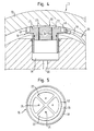
- FIGS 4 and 5 show a modified embodiment of the invention Bend adjustment roller 10, in which by the Temperature influencing means 26 supplied fluid one the pocket area 50 of the respective hydrostatic support member 16 enclosing Annular space 46 is supplied.
- the width of the annular space 46 bounding to the outside Bridge 48 significantly smaller than the width of this between Annulus 46 and the pocket portion 50 provided web 52nd
- the present embodiment has the advantage that the Cooling oil independent of the direction of rotation of the cylinder via a supply line 54 can be supplied. After the outer web 48 essential narrower than the inner bridge, the pressure in the annular channel 46 and the friction can be kept low. Another advantage of this embodiment is that even with completely empty roller created in the inlet of the support member 16 is sufficient cooling oil, which at high Speed can be introduced under the support member 16.
Landscapes
- Engineering & Computer Science (AREA)
- General Engineering & Computer Science (AREA)
- Mechanical Engineering (AREA)
- Physics & Mathematics (AREA)
- Fluid Mechanics (AREA)
- Rolls And Other Rotary Bodies (AREA)
- Paper (AREA)
Abstract
Description
| Außendurchmesser | 1016 mm |
| Innendurchmesser | 780 mm |
| Stützquellengröße | 70 mm Kolbendurchmesser |
| Ölviskosität | ISO VG 68 (Mineralöl) |
| Zulauftemperatur | 40°C für alle Ströme (Stützquelle und Kühlöl) |
- Figur 1
- ein Diagramm, in dem für zwei verschiedene Kolbendrücke jeweils die sich nach einer Stützquelle ergebende Öltemperatur über dem Kühlölstrom (Nebenstrom) dargestellt ist,
- Figur 2
- ein Diagram, in dem für zwei verschiedene Kolbendrücke jeweils die berechnete Rücklauftemperatur über dem Kühlölstrom (Nebenstrom) dargestellt ist,
- Figur 3
- eine schematische geschnittene Teildarstellung einer Ausführungsform einer erfindungsgemäßen Durchbiegungseinstellwalze,
- Figur 4
- eine schematische geschnittene Teildarstellung einer weiteren Ausführungsform einer erfindungsgemäßen Durchbiegungseinstellwalze und
- Figur 5
- eine schematische Draufsicht des in der Figur 4 gezeigten Stützelements.
- 10
- Durchbiegungseinstellwalze
- 12
- Walzenmantel
- 14
- Joch
- 16
- Stützelement
- 18
- Druckraum
- 20
- Kanal
- 22
- Hydrostatiktasche
- 24
- Drossel, Kapillare
- 26
- Temperaturbeeinflussungseinrichtung
- 28
- Fluidstrom
- 30
- Ringraum
- 32
- Düse
- 34
- Ventil
- 36
- Ventilkörper
- 38
- Feder
- 40
- Kanal
- 42
- Kanal
- 44
- Leitung
- 46
- Ringraum
- 48
- Steg
- 50
- Taschenbereich
- 52
- Steg
- 54
- Versorgungsleitung
- X
- Walzenachse
Claims (15)
- Durchbiegungseinstellwalze (10) mit einem umlaufenden Walzenmantel (12), einem den Walzenmantel (12) axial durchsetzenden drehfesten Joch (14), mehreren in Richtung der Walzenachse (X) hintereinander am Joch angeordneten hydrostatischen Stützelementen (16), die jeweils durch eine druckfluidbetätigte Zylinder/Kolben-Einheit gebildet sind und auf die Innenseite des Walzenmantels (12) eine Stützkraft ausüben, und einer Einrichtung (26) zur Beeinflussung der Walzentemperatur über wenigstens einen von der Druckfluidbeaufschlagung der Stützelemente (16) getrennten Fluidstrom (28), wobei die Stützelemente (16) einzeln und/oder gruppenweise ansteuerbar sind, wodurch sich entsprechende, in Richtung der Walzenachse aufeinanderfolgende Walzenzonen ergeben, und wobei eine jeweilige lokale Beaufschlagung der verschiedenen Walzenzonen durch die Temperaturbeeinflussungseinrichtung (26) in Abhängigkeit vom Kolbendruck des Stützelements (16) bzw. der Stützelementgruppe der jeweiligen Walzenzone erfolgt,
dadurch gekennzeichnet , dass mittels der Temperaturbeeinflussungseinrichtung (26) die zwischen dem Walzenmantel (12) und dem Joch (14) vorgesehenen Ringräume (30) der verschiedenen Walzenzonen jeweils in einem in Walzenumlaufrichtung betrachtet außerhalb des betreffenden Stützelements (16) bzw. Stützelementgruppe liegenden Bereich mit dem betreffenden Fluid beaufschlagbar sind. - Durchbiegungseinstellwalze nach Anspruch 1,
dadurch gekennzeichnet , dass mittels der Temperaturbeeinflussungseinrichtung (26) zumindest ein Teil der Walzenzonen jeweils mit einem Kühlfluid beaufschlagbar ist. - Durchbiegungseinstellwalze nach Anspruch 1 oder 2,
dadurch gekennzeichnet , dass mittels der Temperaturbeeinflussungseinrichtung (26) zumindest ein Teil der Walzenzonen jeweils mit einem Heizfluid beaufschlagbar ist. - Durchbiegungseinstellwalze nach einem der vorhergehenden Ansprüche,
dadurch gekennzeichnet , dass die mittels der Temperaturbeeinflussungseinrichtung (26) lokal einer jeweiligen Walzenzone zugeführte Fluidmenge in Abhängigkeit vom Kolbendruck des betreffenden Stützelements (16) bzw. der betreffenden Stützelementgruppe variierbar ist. - Durchbiegungseinstellwalze nach einem der vorhergehenden Ansprüche,
dadurch gekennzeichnet , dass die Temperaturbeeinflussungseinrichtung (26) Düsen (32) umfaßt, über die das betreffende Fluid in die jeweiligen Walzenzonen einspritzbar ist. - Durchbiegungseinstellwalze nach Anspruch 5,
dadurch gekennzeichnet , dass den Düsen (32) jeweils ein Ventil (34) vorgeschaltet ist, über das die jeweilige Fluidmenge in Abhängigkeit vom jeweiligen Kolbendruck steuerbar ist. - Durchbiegungseinstellwalze nach Anspruch 6,
dadurch gekennzeichnet , dass das Ventil (34) so ausgeführt ist, dass es mit zunehmend höher werdenden Kolbendrücken zunehmend schließt und umgekehrt. - Durchbiegungseinstellwalze nach Anspruch 6 oder 7,
dadurch gekennzeichnet , dass das Ventil (34) so ausgeführt und/oder ansteuerbar ist, dass es bei Kolbendrücken oberhalb eines vorgebbaren oberen Grenzwertes zumindest im wesentlichen ganz geschlossen und/oder bei Kolbendrücken unterhalb einem vorgebbaren unteren Grenzwert zumindest im wesentlichen ganz geöffnet ist. - Durchbiegungseinstellwalze nach einem der Ansprüche 6 bis 8,
dadurch gekennzeichnet , dass der Ventilquerschnitt über einen federbelasteten Ventilkörper (36) variierbar ist, der entgegen der Federkraft (38) durch den Kolbendruck beaufschlagbar ist. - Durchbiegungseinstellwalze nach einem der Ansprüche 5 bis 9,
dadurch gekennzeichnet , dass der Düsenquerschnitt an die Stützelementgröße angepaßt ist, um insbesondere eine konstante Mischtemperatur im Walzeninnern zu erzeugen. - Durchbiegungseinstellwalze nach einem der vorhergehenden Ansprüche,
dadurch gekennzeichnet , dass eine variable, in Abhängigkeit vom Kolbendruck des betreffenden Stützelements (16) bzw. der betreffenden Stützelementgruppe gesteuerte Lenkung eines mittels der Temperaturbeeinflussungseinrichtung (26) lokal einer jeweiligen Walzenzone zugeführten Fluidvolumenstroms vorgesehen ist. - Durchbiegungseinstellwalze nach Anspruch 11,
dadurch gekennzeichnet , dass die Lenkung des Fluidvolumenstroms durch den Kolbendruck gesteuert ist. - Durchbiegungseinstellwalze nach Anspruch 11 oder 12,
dadurch gekennzeichnet , dass die Lenkung des Fluidvolumenstroms über variable Leitbleche erfolgt. - Durchbiegungseinstellwalze nach einem der vorhergehenden Ansprüche,
dadurch gekennzeichnet , dass die Breite des den Ringraum (46) nach außen begrenzenden Steges (48) kleiner ist als die Breite des zwischen diesem Ringraum (46) und dem Taschenbereich vorgesehenen Steges (52). - Durchbiegungseinstellwalze nach einem der vorhergehenden Ansprüche,
dadurch gekennzeichnet , dass als Druckfluid und/oder als der getrennten Temperaturbeeinflussung dienendes Fluid jeweils Öl vorgesehen ist.
Applications Claiming Priority (3)
| Application Number | Priority Date | Filing Date | Title |
|---|---|---|---|
| DE10136270A DE10136270A1 (de) | 2001-07-25 | 2001-07-25 | Durchbiegungseinstellwalze |
| DE10136270 | 2001-07-25 | ||
| EP02009967A EP1279766B1 (de) | 2001-07-25 | 2002-05-03 | Durchbiegungseinstellwalze |
Related Parent Applications (1)
| Application Number | Title | Priority Date | Filing Date |
|---|---|---|---|
| EP02009967A Division EP1279766B1 (de) | 2001-07-25 | 2002-05-03 | Durchbiegungseinstellwalze |
Publications (2)
| Publication Number | Publication Date |
|---|---|
| EP1600555A1 true EP1600555A1 (de) | 2005-11-30 |
| EP1600555B1 EP1600555B1 (de) | 2006-09-27 |
Family
ID=7693070
Family Applications (2)
| Application Number | Title | Priority Date | Filing Date |
|---|---|---|---|
| EP02009967A Expired - Lifetime EP1279766B1 (de) | 2001-07-25 | 2002-05-03 | Durchbiegungseinstellwalze |
| EP05018941A Expired - Lifetime EP1600555B1 (de) | 2001-07-25 | 2002-05-03 | Durchbiegungseinstellwalze |
Family Applications Before (1)
| Application Number | Title | Priority Date | Filing Date |
|---|---|---|---|
| EP02009967A Expired - Lifetime EP1279766B1 (de) | 2001-07-25 | 2002-05-03 | Durchbiegungseinstellwalze |
Country Status (3)
| Country | Link |
|---|---|
| US (1) | US6659926B2 (de) |
| EP (2) | EP1279766B1 (de) |
| DE (3) | DE10136270A1 (de) |
Cited By (1)
| Publication number | Priority date | Publication date | Assignee | Title |
|---|---|---|---|---|
| CN110617272A (zh) * | 2019-09-27 | 2019-12-27 | 广东工业大学 | 一种气浮轴承 |
Families Citing this family (17)
| Publication number | Priority date | Publication date | Assignee | Title |
|---|---|---|---|---|
| DE10137326A1 (de) * | 2001-07-31 | 2003-02-20 | Voith Paper Patent Gmbh | Durchbiegungseinstellwalze |
| DE10249796A1 (de) * | 2002-10-24 | 2004-05-13 | Eduard Küsters Maschinenfabrik GmbH & Co. KG | Durchbiegungseinstellwalze |
| DE102004006514A1 (de) * | 2004-02-10 | 2005-08-25 | Voith Paper Patent Gmbh | Verfahren zur Beheizung einer Walze sowie beheizbare Walze |
| US7258654B2 (en) * | 2004-03-05 | 2007-08-21 | Rohm and Haas Dënmark Finance A/S | Compliant pressure roller with uniform nip pressure |
| DE102004022377A1 (de) * | 2004-05-06 | 2005-12-08 | Voith Paper Patent Gmbh | Biegeausgleichswalze |
| DE102004034830A1 (de) | 2004-07-19 | 2006-03-16 | Voith Paper Patent Gmbh | Biegeausgleichswalze |
| DE102005025950A1 (de) * | 2005-06-06 | 2006-12-07 | Voith Patent Gmbh | Biegeausgleichswalze |
| DE102006030717A1 (de) * | 2006-07-04 | 2008-01-10 | Voith Patent Gmbh | Biegeausgleichswalze und Verfahren zum Betreiben einer Biegeausgleichswalze |
| GB2456344B (en) * | 2008-01-14 | 2012-04-18 | Upm Ltd | Aerostatic bearing |
| FI121896B (fi) * | 2010-02-05 | 2011-05-31 | Metso Paper Inc | Taipumasäädettävä tela ja järjestelmä |
| ITTO20110445A1 (it) * | 2011-05-19 | 2012-11-20 | Tecnau Srl | "equipaggiamento per perforazioni trasversali di lunghezze variabili, ad alta velocita, su moduli continui in movimento" |
| US10123846B2 (en) | 2014-11-13 | 2018-11-13 | Intuitive Surgical Operations, Inc. | User-interface control using master controller |
| US10786315B2 (en) | 2014-11-13 | 2020-09-29 | Intuitive Surgical Operations, Inc. | Interaction between user-interface and master controller |
| CN108248113A (zh) * | 2017-12-28 | 2018-07-06 | 叶金吉 | 用于纸箱包装的设备 |
| CN108263025A (zh) * | 2017-12-28 | 2018-07-10 | 叶金吉 | 一种用于包装纸箱成型的方法 |
| CN108248112A (zh) * | 2017-12-28 | 2018-07-06 | 叶金吉 | 一种包装纸箱的成型方法 |
| JP2024544501A (ja) * | 2021-11-04 | 2024-12-03 | マシューズ インターナショナル ゲーエムベーハー | 電極製造用乾式コーティング工程に使用するローラー |
Citations (4)
| Publication number | Priority date | Publication date | Assignee | Title |
|---|---|---|---|---|
| US4282638A (en) * | 1979-01-22 | 1981-08-11 | Escher Wyss Limited | Controlled deflection roll |
| US4282639A (en) * | 1979-01-23 | 1981-08-11 | Escher Wyss Limited | Heated controlled deflection roll |
| US5033176A (en) * | 1989-07-28 | 1991-07-23 | J. M. Voith Gmbh | Sag compensating roll for roll presses |
| US5101544A (en) * | 1988-10-15 | 1992-04-07 | Eduart Kusters Maschinenfabrik GmbH & Co. KG | Apparatus and method for regulating temperature in a flexure-controllable roll |
Family Cites Families (8)
| Publication number | Priority date | Publication date | Assignee | Title |
|---|---|---|---|---|
| FI82125C (fi) | 1988-02-10 | 1991-01-10 | Valmet Paper Machinery Inc | Foerfarande foer reglering av temperaturen av en boejningskompenserad vals med reglerbar temperatur och ett temperaturregleringssystem avsedd foer genomfoering av foerfarandet. |
| CA2086007C (en) * | 1991-05-03 | 1999-04-13 | Rolf Lehmann | Roll with adjustable deflection and its use |
| DE4223359A1 (de) * | 1992-07-16 | 1994-01-20 | Escher Wyss Gmbh | Heiz- oder Kühlwalze |
| US5592875A (en) * | 1994-09-16 | 1997-01-14 | Stowe Woodward Licensco, Inc. | Roll having means for determining pressure distribution |
| FI100481B (fi) * | 1995-10-23 | 1997-12-15 | Valmet Corp | Menetelmä taipumakompensoidun telan liukulaakeroidun telavaipan päätya lueiden lämpötilan säätämiseksi |
| FI110014B (fi) * | 1996-10-23 | 2002-11-15 | Metso Paper Inc | Menetelmä paperikoneen tai vastaavan telan putkimaisen telavaipan liukulaakeroimiseksi ja liukulaakeroitu tela |
| ATE264174T1 (de) * | 1997-02-28 | 2004-04-15 | Chiba Machine Industry Corp | Verfahren und vorrichtung zum formen von folienprodukten |
| US6315703B1 (en) * | 1999-05-07 | 2001-11-13 | Kleinewefers Textilmaschinen Gmbh | Pressure treatment roller |
-
2001
- 2001-07-25 DE DE10136270A patent/DE10136270A1/de not_active Withdrawn
-
2002
- 2002-05-03 DE DE50208298T patent/DE50208298D1/de not_active Expired - Lifetime
- 2002-05-03 EP EP02009967A patent/EP1279766B1/de not_active Expired - Lifetime
- 2002-05-03 EP EP05018941A patent/EP1600555B1/de not_active Expired - Lifetime
- 2002-05-03 DE DE50208386T patent/DE50208386D1/de not_active Expired - Lifetime
- 2002-07-23 US US10/200,429 patent/US6659926B2/en not_active Expired - Fee Related
Patent Citations (4)
| Publication number | Priority date | Publication date | Assignee | Title |
|---|---|---|---|---|
| US4282638A (en) * | 1979-01-22 | 1981-08-11 | Escher Wyss Limited | Controlled deflection roll |
| US4282639A (en) * | 1979-01-23 | 1981-08-11 | Escher Wyss Limited | Heated controlled deflection roll |
| US5101544A (en) * | 1988-10-15 | 1992-04-07 | Eduart Kusters Maschinenfabrik GmbH & Co. KG | Apparatus and method for regulating temperature in a flexure-controllable roll |
| US5033176A (en) * | 1989-07-28 | 1991-07-23 | J. M. Voith Gmbh | Sag compensating roll for roll presses |
Cited By (2)
| Publication number | Priority date | Publication date | Assignee | Title |
|---|---|---|---|---|
| CN110617272A (zh) * | 2019-09-27 | 2019-12-27 | 广东工业大学 | 一种气浮轴承 |
| CN110617272B (zh) * | 2019-09-27 | 2021-08-13 | 广东工业大学 | 一种气浮轴承 |
Also Published As
| Publication number | Publication date |
|---|---|
| US20030022773A1 (en) | 2003-01-30 |
| DE50208386D1 (de) | 2006-11-23 |
| DE10136270A1 (de) | 2003-03-13 |
| DE50208298D1 (de) | 2006-11-09 |
| EP1600555B1 (de) | 2006-09-27 |
| EP1279766B1 (de) | 2006-10-11 |
| EP1279766A1 (de) | 2003-01-29 |
| US6659926B2 (en) | 2003-12-09 |
Similar Documents
| Publication | Publication Date | Title |
|---|---|---|
| EP1279766B1 (de) | Durchbiegungseinstellwalze | |
| DE3516535C2 (de) | ||
| DE4107440C1 (de) | ||
| DE3925019C2 (de) | ||
| EP0889776B1 (de) | Verfahren zur beeinflussung des walzenspaltes eines glättwerkes und drehbar gelagerte walze | |
| EP0188238B1 (de) | Beheizbare Kalanderwalze mit einem einen Strömungsspalt bildenden Verdrängerkörper | |
| EP1281879B1 (de) | Durchbiegungseinstellwalze | |
| EP0364753A2 (de) | Durchbiegungssteuerbare Walze mit Zuimpfung | |
| DE2652211A1 (de) | Walzgeruest mit kuehlmittel-sprueheinrichtung | |
| DE19544978C2 (de) | Preßwalze | |
| EP1279767B1 (de) | Durchbiegungseinstellwalze | |
| EP0338236A2 (de) | Hydrostatisch innenabgestützte Walze | |
| EP2248945B1 (de) | Hydostatisches Stützelement | |
| DE3838852C1 (de) | ||
| EP0870865A2 (de) | Schuhpresseinheit | |
| DE19824542B4 (de) | Walze, Kalander und Verfahren zum Betrieb einer Walze | |
| DE69607935T2 (de) | Verfahren zur regelung der temperatur in den endflächen des rollmantels einer durchbiegungseinstellwalze mit gleitlager | |
| DE69018311T2 (de) | Verfahren zur Steuerung der Temperatur einer Walze mit anpassbarer Biegelinie und Regelungssystem zur Durchführung des Verfahrens. | |
| EP1505202B1 (de) | Vorrichtung zur Behandlung einer Materialbahn | |
| DE4017433A1 (de) | Walzenpresse | |
| AT506500B1 (de) | Belastungselement für eine faserbahnmaschine | |
| DE29908069U1 (de) | Durchbiegungseinstellwalze | |
| EP0452633A1 (de) | Stützelement und damit ausgerüstete Walze | |
| AT502585B1 (de) | Durchbiegungseinstellwalze für papier-/kartonmaschinen oder ausrüstungsmaschinen | |
| DE2403970A1 (de) | Vorrichtung zum kraeuseln synthetischer fadenscharen |
Legal Events
| Date | Code | Title | Description |
|---|---|---|---|
| PUAI | Public reference made under article 153(3) epc to a published international application that has entered the european phase |
Free format text: ORIGINAL CODE: 0009012 |
|
| AC | Divisional application: reference to earlier application |
Ref document number: 1279766 Country of ref document: EP Kind code of ref document: P |
|
| AK | Designated contracting states |
Kind code of ref document: A1 Designated state(s): DE FI SE |
|
| GRAC | Information related to communication of intention to grant a patent modified |
Free format text: ORIGINAL CODE: EPIDOSCIGR1 |
|
| GRAP | Despatch of communication of intention to grant a patent |
Free format text: ORIGINAL CODE: EPIDOSNIGR1 |
|
| 17P | Request for examination filed |
Effective date: 20060223 |
|
| AKX | Designation fees paid |
Designated state(s): DE FI SE |
|
| GRAS | Grant fee paid |
Free format text: ORIGINAL CODE: EPIDOSNIGR3 |
|
| GRAA | (expected) grant |
Free format text: ORIGINAL CODE: 0009210 |
|
| RAP1 | Party data changed (applicant data changed or rights of an application transferred) |
Owner name: VOITH PATENT GMBH |
|
| AC | Divisional application: reference to earlier application |
Ref document number: 1279766 Country of ref document: EP Kind code of ref document: P |
|
| AK | Designated contracting states |
Kind code of ref document: B1 Designated state(s): DE FI SE |
|
| REG | Reference to a national code |
Ref country code: SE Ref legal event code: TRGR |
|
| REF | Corresponds to: |
Ref document number: 50208298 Country of ref document: DE Date of ref document: 20061109 Kind code of ref document: P |
|
| PLBE | No opposition filed within time limit |
Free format text: ORIGINAL CODE: 0009261 |
|
| STAA | Information on the status of an ep patent application or granted ep patent |
Free format text: STATUS: NO OPPOSITION FILED WITHIN TIME LIMIT |
|
| 26N | No opposition filed |
Effective date: 20070628 |
|
| PGFP | Annual fee paid to national office [announced via postgrant information from national office to epo] |
Ref country code: SE Payment date: 20110513 Year of fee payment: 10 |
|
| PGFP | Annual fee paid to national office [announced via postgrant information from national office to epo] |
Ref country code: FI Payment date: 20110512 Year of fee payment: 10 |
|
| PGFP | Annual fee paid to national office [announced via postgrant information from national office to epo] |
Ref country code: DE Payment date: 20110520 Year of fee payment: 10 |
|
| REG | Reference to a national code |
Ref country code: SE Ref legal event code: EUG |
|
| PG25 | Lapsed in a contracting state [announced via postgrant information from national office to epo] |
Ref country code: FI Free format text: LAPSE BECAUSE OF NON-PAYMENT OF DUE FEES Effective date: 20120503 |
|
| PG25 | Lapsed in a contracting state [announced via postgrant information from national office to epo] |
Ref country code: SE Free format text: LAPSE BECAUSE OF NON-PAYMENT OF DUE FEES Effective date: 20120504 |
|
| REG | Reference to a national code |
Ref country code: DE Ref legal event code: R119 Ref document number: 50208298 Country of ref document: DE Effective date: 20121201 |
|
| PG25 | Lapsed in a contracting state [announced via postgrant information from national office to epo] |
Ref country code: DE Free format text: LAPSE BECAUSE OF NON-PAYMENT OF DUE FEES Effective date: 20121201 |