EP1600379A2 - Aircraft assembly rig - Google Patents
Aircraft assembly rig Download PDFInfo
- Publication number
- EP1600379A2 EP1600379A2 EP05076794A EP05076794A EP1600379A2 EP 1600379 A2 EP1600379 A2 EP 1600379A2 EP 05076794 A EP05076794 A EP 05076794A EP 05076794 A EP05076794 A EP 05076794A EP 1600379 A2 EP1600379 A2 EP 1600379A2
- Authority
- EP
- European Patent Office
- Prior art keywords
- pick
- receiving element
- assembly tool
- elongate members
- fixture frame
- Prior art date
- Legal status (The legal status is an assumption and is not a legal conclusion. Google has not performed a legal analysis and makes no representation as to the accuracy of the status listed.)
- Granted
Links
- 239000004411 aluminium Substances 0.000 claims description 10
- 229910052782 aluminium Inorganic materials 0.000 claims description 10
- XAGFODPZIPBFFR-UHFFFAOYSA-N aluminium Chemical compound [Al] XAGFODPZIPBFFR-UHFFFAOYSA-N 0.000 claims description 10
- 238000010276 construction Methods 0.000 claims description 8
- 238000006073 displacement reaction Methods 0.000 claims description 2
- 238000000034 method Methods 0.000 description 15
- 238000004519 manufacturing process Methods 0.000 description 8
- 230000008569 process Effects 0.000 description 8
- 238000013461 design Methods 0.000 description 7
- 238000012986 modification Methods 0.000 description 6
- 230000004048 modification Effects 0.000 description 6
- 238000005259 measurement Methods 0.000 description 5
- 230000003014 reinforcing effect Effects 0.000 description 4
- 238000011960 computer-aided design Methods 0.000 description 3
- 229910000831 Steel Inorganic materials 0.000 description 2
- 230000008901 benefit Effects 0.000 description 2
- 229910052751 metal Inorganic materials 0.000 description 2
- 239000002184 metal Substances 0.000 description 2
- 239000010959 steel Substances 0.000 description 2
- 238000013519 translation Methods 0.000 description 2
- 230000014616 translation Effects 0.000 description 2
- FGUUSXIOTUKUDN-IBGZPJMESA-N C1(=CC=CC=C1)N1C2=C(NC([C@H](C1)NC=1OC(=NN=1)C1=CC=CC=C1)=O)C=CC=C2 Chemical compound C1(=CC=CC=C1)N1C2=C(NC([C@H](C1)NC=1OC(=NN=1)C1=CC=CC=C1)=O)C=CC=C2 FGUUSXIOTUKUDN-IBGZPJMESA-N 0.000 description 1
- 230000004075 alteration Effects 0.000 description 1
- 230000008602 contraction Effects 0.000 description 1
- 230000001934 delay Effects 0.000 description 1
- 230000002708 enhancing effect Effects 0.000 description 1
- 230000002045 lasting effect Effects 0.000 description 1
- 238000012423 maintenance Methods 0.000 description 1
- 230000008439 repair process Effects 0.000 description 1
- 239000007787 solid Substances 0.000 description 1
Images


Classifications
-
- B—PERFORMING OPERATIONS; TRANSPORTING
- B64—AIRCRAFT; AVIATION; COSMONAUTICS
- B64F—GROUND OR AIRCRAFT-CARRIER-DECK INSTALLATIONS SPECIALLY ADAPTED FOR USE IN CONNECTION WITH AIRCRAFT; DESIGNING, MANUFACTURING, ASSEMBLING, CLEANING, MAINTAINING OR REPAIRING AIRCRAFT, NOT OTHERWISE PROVIDED FOR; HANDLING, TRANSPORTING, TESTING OR INSPECTING AIRCRAFT COMPONENTS, NOT OTHERWISE PROVIDED FOR
- B64F5/00—Designing, manufacturing, assembling, cleaning, maintaining or repairing aircraft, not otherwise provided for; Handling, transporting, testing or inspecting aircraft components, not otherwise provided for
- B64F5/10—Manufacturing or assembling aircraft, e.g. jigs therefor
-
- Y—GENERAL TAGGING OF NEW TECHNOLOGICAL DEVELOPMENTS; GENERAL TAGGING OF CROSS-SECTIONAL TECHNOLOGIES SPANNING OVER SEVERAL SECTIONS OF THE IPC; TECHNICAL SUBJECTS COVERED BY FORMER USPC CROSS-REFERENCE ART COLLECTIONS [XRACs] AND DIGESTS
- Y10—TECHNICAL SUBJECTS COVERED BY FORMER USPC
- Y10T—TECHNICAL SUBJECTS COVERED BY FORMER US CLASSIFICATION
- Y10T29/00—Metal working
- Y10T29/49—Method of mechanical manufacture
- Y10T29/49764—Method of mechanical manufacture with testing or indicating
- Y10T29/49771—Quantitative measuring or gauging
-
- Y—GENERAL TAGGING OF NEW TECHNOLOGICAL DEVELOPMENTS; GENERAL TAGGING OF CROSS-SECTIONAL TECHNOLOGIES SPANNING OVER SEVERAL SECTIONS OF THE IPC; TECHNICAL SUBJECTS COVERED BY FORMER USPC CROSS-REFERENCE ART COLLECTIONS [XRACs] AND DIGESTS
- Y10—TECHNICAL SUBJECTS COVERED BY FORMER USPC
- Y10T—TECHNICAL SUBJECTS COVERED BY FORMER US CLASSIFICATION
- Y10T29/00—Metal working
- Y10T29/49—Method of mechanical manufacture
- Y10T29/49764—Method of mechanical manufacture with testing or indicating
- Y10T29/49778—Method of mechanical manufacture with testing or indicating with aligning, guiding, or instruction
- Y10T29/4978—Assisting assembly or disassembly
-
- Y—GENERAL TAGGING OF NEW TECHNOLOGICAL DEVELOPMENTS; GENERAL TAGGING OF CROSS-SECTIONAL TECHNOLOGIES SPANNING OVER SEVERAL SECTIONS OF THE IPC; TECHNICAL SUBJECTS COVERED BY FORMER USPC CROSS-REFERENCE ART COLLECTIONS [XRACs] AND DIGESTS
- Y10—TECHNICAL SUBJECTS COVERED BY FORMER USPC
- Y10T—TECHNICAL SUBJECTS COVERED BY FORMER US CLASSIFICATION
- Y10T29/00—Metal working
- Y10T29/49—Method of mechanical manufacture
- Y10T29/49826—Assembling or joining
- Y10T29/49895—Associating parts by use of aligning means [e.g., use of a drift pin or a "fixture"]
-
- Y—GENERAL TAGGING OF NEW TECHNOLOGICAL DEVELOPMENTS; GENERAL TAGGING OF CROSS-SECTIONAL TECHNOLOGIES SPANNING OVER SEVERAL SECTIONS OF THE IPC; TECHNICAL SUBJECTS COVERED BY FORMER USPC CROSS-REFERENCE ART COLLECTIONS [XRACs] AND DIGESTS
- Y10—TECHNICAL SUBJECTS COVERED BY FORMER USPC
- Y10T—TECHNICAL SUBJECTS COVERED BY FORMER US CLASSIFICATION
- Y10T29/00—Metal working
- Y10T29/53—Means to assemble or disassemble
- Y10T29/53961—Means to assemble or disassemble with work-holder for assembly
-
- Y—GENERAL TAGGING OF NEW TECHNOLOGICAL DEVELOPMENTS; GENERAL TAGGING OF CROSS-SECTIONAL TECHNOLOGIES SPANNING OVER SEVERAL SECTIONS OF THE IPC; TECHNICAL SUBJECTS COVERED BY FORMER USPC CROSS-REFERENCE ART COLLECTIONS [XRACs] AND DIGESTS
- Y10—TECHNICAL SUBJECTS COVERED BY FORMER USPC
- Y10T—TECHNICAL SUBJECTS COVERED BY FORMER US CLASSIFICATION
- Y10T29/00—Metal working
- Y10T29/53—Means to assemble or disassemble
- Y10T29/53978—Means to assemble or disassemble including means to relatively position plural work parts
Definitions
- This invention concerns an aircraft assembly tool and a method of manufacturing such a tool.
- Aircraft assembly tools are designed to support aircraft components while they are being worked on and to locate different components together in the correct relative positions during aircraft assembly. Traditionally, each different assembly process has required at least one dedicated assembly tool, which is produced specifically for a given set of components and which is designed to support the components in a particular manner so that assembly operations can be carried out without interference from the tool. Such assembly tools have had to be manufactured to exacting standards.
- a conventional assembly tool comprises a rigid metal jig whose framework is constructed from welded box section steel.
- a plurality of pick-up devices is mounted on the framework for carrying the aircraft components during the assembly process, and these too are conventionally produced from welded steel parts.
- Each assembly tool has to be specifically designed for the component to be supported, and the requirement in the aircraft industry for an aircraft component to be supported with a very high degree of precision means that every stage of construction of the conventional jig has to be carried out to very exacting levels of accuracy. This makes the production of such jigs time-consuming and costly, and they cannot easily be reconfigured for supporting different components, or repaired/adjusted so as to accommodate wear and tear.
- the present invention seeks to provide an assembly tool, and a method of producing such a tool, which is more versatile than conventional arrangements and in which the need for precision is confined to some parts only of the tool and its production.
- an aircraft assembly tool for supporting an aircraft component comprising:
- the fixture frame may be constructed from lengths of extruded aluminium section with the fastening means securing the lengths together.
- the extruded aluminium section may be formed with longitudinal channels having lips along their edges, and the fastening means may comprise threaded connecting elements receivable in a channel of one section and threaded receiving means provided by or receivable within a channel of another section.
- the elongate members are rectangular in cross-section, or have at least one substantially flat, planar surface to which the pick-up devices can be clamped, and moved along if necessary - to adapt to a different component, for example. It is also important that these planar surfaces of the elongate members are so configured as to remain undistorted when a pick-up device is mounted thereon, particularly when the device is under load from the weight of the aircraft component.
- This preferred embodiment has the additional advantage that it facilitates rapid movement and/or re-alignment/re-positioning of the pick-up devices.
- the range of movement necessary to accommodate wear and tear or to adapt to a different component may easily and accurately be modelled in the computer as a movement in a single dimension (along the axes of the elongate member, but without any rotation thereabouts) while taking account of the six degrees of freedom of adjustment possible for the receiving element.
- the required re-alignment may be accommodated by removing the pick-up device abd mounting it instead on one the other planar surfaces of the elongate member.
- the pick-up devices are preferably of universal construction.
- a universal pick-up device for mounting on a fixture frame to provide an aircraft assembly tool for supporting an aircraft component during the assembly process
- the pick-up device comprising a mounting element for mounting the device on the fixture frame, a receiving element for carrying the aircraft component, and a plurality of elongate members having predetermined lengths connected together by means of clamping elements so as to allow at least three degrees of movement of the receiving element along at least two orthogonal axes and around at least one axis coplanar with the orthogonal axes.
- the combination of elongate members and clamping elements are arranged to allow six degrees of freedom of movement of the receiving element along and around three orthogonal axes.
- the pick-up devices may also be formed from aluminium.
- the aircraft assembly tool and pick-up device according to the present invention offer a number of significant advantages.
- the invention provides a flexible assembly tooling system that is fully adjustable and re-usable. Adjustments and alterations to the assembly tooling can readily be effected, for example in order to accommodate modifications in the design of the aircraft components. Maintenance simply involves replacement of individual frame members and/or pick-up devices in the event of excessive wear, or repositioning of frame members and/or pick-up devices if relative movement has occurred over time. Furthermore, existing assembly tools can be altered to suit different aircraft components once a particular assembly operation is complete.
- Another aspect of the present invention is the method of producing the aircraft assembly tool.
- a method of producing an aircraft assembly tool for supporting an aircraft component comprising:
- step f) comprises setting a receiving element approximately in its predetermined position and orientation, and iterating the steps of measuring the actual position and orientation of the receiving element and moving it towards the predetermined position and orientation until it achieves the predetermined position and orientation.
- the predetermined positions and orientations for the receiving elements of the pick-up devices are determined from computer aided design data for each aircraft component.
- each receiving element is measured by a laser tracking device.
- the present method and assembly tool whilst specifically designed for use in the aircraft industry, may also advantageously have application in other fields, for example in the automotive industry.
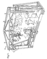
- the assembly tool 10 comprises a fixture frame 12, constructed from a plurality of elongate members 14 of square and rectangular cross-section connected to one another to form a substantially rectangular framework 16.
- the majority of the elongate members 14 are connected to one another at right angles to form the framework 16 but some of them form diagonal members 18 serving as reinforcing struts for enhancing the rigidity of the framework 16.
- the fixture frame 12 serves as a support structure for an aircraft component during assembly.
- a plurality of pick-up devices 20 mounted on the fixture frame 12 serve to hold the component during the assembly process, and are situated at predetermined locations in relation to the fixture frame 12 for engaging and carrying the component at preselected support positions of the component.
- the assembly tool 10 shown in Figure 1 is specifically designed for the assembly of a particular aircraft component, or a small range of components, in this instance being for the assembly of an aircraft fuselage: the precise design of the fixture frame 12 and the location and orientation of the pick-up devices 20 would be different for the assembly of another part of an aircraft.
- the accuracy of construction of the fixture frame 12 and the accuracy of location of the pick-up devices 20 in relation to the fixture frame 12 are relatively unimportant. What matters is that the positions at which the pick-up devices 20 engage the aircraft component, and the orientation of the pick-up devices at these positions, are highly accurately determined, as described below.
- the elongate members 14 are formed from extruded aluminium section, which is cut to predetermined lengths suited to the specific fixture frame 12 required.
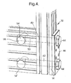
- Figures 2, 3, 4 and 6 show different profiles for the extruded section, which is illustrated as being square or rectangular in each case.
- Longitudinally extending channels 22 are formed along the four longitudinal surfaces 24 of the member 14, and are each flanked on both sides by lips 26.
- fastening means 32 may, for example, comprise a threaded connecting element 34 inserted perpendicularly through the central portion 28 of one member 14.
- the connecting element 34 has a locating head 36 which sits within a respective one of the channels 22 of the member 14, and a threaded shaft 38 which then projects at right angles from the member 14.
- a second elongate member 14 is fitted at right angles to the first so that its end face 40 abuts an adjacent surface 24 of the first elongate member 14.
- the projecting shaft 38 of the threaded connecting element 34 can thus be tapped into the central bore 30 of the second elongate member 14. A secure a lasting connection may thus be provided.
- the fastening means 32 may alternatively comprise a threaded connecting element 52 receivable within one channel 22 of a first elongate member 14, and a locating collar 54 arranged to be fitted within a receiving well 56 formed in the associated surface 24 near the end face 40 of this elongate member 14.
- a second such connecting element 52 will also be provided in the same manner on the opposite side of the first elongate member 14. This second connecting element 52 will then engage a second receiving element 60 in the same channel 22 of the second elongate member 14 in order to ensure a secure connection between the two members 14.
- Figures 2 and 3 illustrate a simple square extruded section for the elongate members 14 for the sake of clarity.
- the elongate members 14 may have more complex sections and may require multiple fastening means 32 employing groups of fasteners.
- a cross section which is substantially square or rectangular is advantageous in terms of strength and rigidity.
- a further form of fastening means 32 shown in Figure 4 may be employed for a high strength joint.
- the fastening means 32 may comprise a pair of threaded bolts 42, each having a respective head 44 engaged with a structural plate 46 and each extending right through a transverse clearance hole 48 in one elongate member 14 of square section.
- the stem 50 of each bolt 42 engages a threaded bore within a respective locating collar 54, which is received within a receiving well 56 of another elongate member 14, this time of rectangular section, as shown in Figure 3.
- the load is then distributed across the first elongate member 14 by means of the plate 46.
- a number of diagonal reinforcing struts 18 may be provided which are similarly formed from extruded aluminium section. Such struts are connected in place by means of pairs of hinge elements 62, 64 mounted respectively between the ends of the diagonal reinforcing struts 18 and adjacent portions of the framework 16 as shown in Figures 1 and 7, for example.
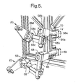
- each pick-up device 20 comprises an arrangement of tubes 66 and clamping elements 68 connected together to permit movement with at least three, and preferably six, degrees of freedom.
- each pick-up device 20 comprises a mounting element 70 for mounting the pick-up device 20 on the fixture frame 12, for example by means of bolts 72 which engage with nuts (not shown) in the channels 22 of the associated elongate members 14.
- the mounting element 70 has a substantially flat planar surface arranged to co-operate with the adjacent flat planar surface of the member 14, so that the pick-up device 20 can readily be moved along the surface of the member 14, for purposes of location or adjustment, prior to being bolted securely in place.
- a first clamping element 68a is fixed to the mounting element 70 using the bolts 72. Extending from the first clamping element 68a is a first tube 66a terminating in a second clamping element 68b as illustrated. A second tube 66b, arranged perpendicular to the first tube 66a, extends between the clamping element 68b and a further clamping element 68c. Likewise, a third tube 66c is arranged at right angles to the second tube 66b and extends between the clamping element 68c and a further clamping element 68d. Finally, the clamping element 68d is connected by means of bolts 74 to a receiving element 76, which serves in use for engaging and holding the aircraft component.
- each clamping element 68 comprises a block 78 of aluminium provided with cylindrical openings 80 for rotatably and slidably receiving the tubes 66.
- a respective slot 82 is formed in the block 78 along one side of each cylindrical opening 80 to provide a gap which is closable by means of further bolts 84 to ensure that the clamping element 68 firmly engages and locks onto a respective tube 66 in the required position.
- tubes 66 can be rotated relative to one another about, and/or displaced relative to one another along, three mutually perpendicular axes.
- the pick-up devices 20 can readily be effected to accommodate: a) minor variations in the positions of the pick-up devices 20; and b) movements of the fixture frame 12 that occur over time due to factors such as wear and tear, and thermal expansion and contraction.
- the pick-up devices 20 can easily be adapted to accommodate minor design modifications in the aircraft component itself, simply by altering the location of the existing pick-up devices 20 relative to the fixture frame 12, and the position and/or the orientation of the receiving elements 76, or alternatively by adding additional pick-up devices 20.
- the parts for the fixture frame 12 are produced by cutting lengths of extruded aluminium section to the required dimensions to provide the elongate members 14.
- Such elongate members 14 are connected together by fastening means 32 as described previously, and subsequently any additional elongate members 14 forming the reinforcing struts 18 are connected into the framework 16 as previously described.
- the pick-up devices 20 are selected and mounted on the fixture frame 12 at the predetermined locations.
- each pick-up device 20 would have been preformed from predetermined lengths of tubing joined by similar clamping elements.
- the next step of the manufacturing process simply involves selecting the required number of pick-up devices 20 and mounting them on the fixture frame 12 in locations predetermined from the computer aided design data.
- the manufacturing process can be carried out to a level of accuracy allowing for standard tolerances.
- the following stages of the manufacturing process require a much higher degree of accuracy within very fine tolerances indeed:
- the pick-up devices 20 then have to be set into the required orientation in order to hold the aircraft component at predetermined precise points of its structure and in a predetermined precise directions.
- a laser tracker or other measuring device is employed.
- the laser tracker comprises a computer controlled laser measuring apparatus into which the data relating to the predetermined position and orientation of the receiving element 76 of each pick-up device 20 has already been programmed.
- the pick-up device 20 is first mounted roughly in the required position and orientation on the fixture frame 12, and the laser tracker is then used to measure the initial position and orientation of the receiving element 76 and to compare this position to the required position.
- the results of the comparison yield adjustment data following which the pick-up device 20 is correspondingly adjusted to bring the receiving element 76 to a new position and orientation.
- the laser tracker takes another measurement of the current state and again compares it to the predetermined requirements. This yields further adjustment data and a further adjustment is made accordingly until the predetermined position and orientation is achieved within the required fine tolerances.
- the setting of the receiving element 76 of the pick-up device 20 involves repeated steps of measurement of a current position and orientation, comparison of a current position and orientation with the predetermined position and orientation, and adjustment to reduce the error between the two.
- stage 1 a face 86 of the receiving element 76 and a hole 88 within that face are adjusted to predetermined positions and orientations.
- the face 86 of the receiving element 76 is set square to a required plane in space by successive rotations of the tubes 66a, 66b and 66c relative to each of the X,Y and Z axes in turn. Following each rotation, measurements are taken across the face 86 by the laser tracker and a comparison is made with the predetermined orientation.
- the hole 88 in the face 86 of the receiving element is moved into the required position by effecting successive translations along the X,Y and Z axes in turn by effecting displacements of the clamping elements 68b, 68c and 68d along the tubes 66a, 66b and 66c respectively.
- measurements are taken by the laser tracker after each successive translation and a comparison is made with the predetermined position.
- a profile board 90 is mounted in a predetermined position and orientation relative to the receiving element 76.
- the profile board 90 is moved to a predetermined position relative to the face 86 of the receiving element 76 with the aid of the laser tracker.
- the profile board 98 is then rotatably attached to the receiving element 76 by inserting a pin through a hole 92 in the profile board 90 and a corresponding hole (not shown) in the face 86.
- a second hole 94 in the profile board 90 is positioned with the aid of the laser tracker by repeated rotational adjustment of the board 90, followed on each occasion by measurement of the current position of the hole 94 and comparison with the predetermined position. This brings a locating edge 96 of the profile board 90 into a predetermined position, at which point the profile board is fixed to the receiving element 76.
- gripping fingers 98 are attached to the profile board 90 and hence the receiving element 76.
- the adjustments of the parts of the pick-up device 20 during the two stages of the setting process are carried out manually. It is equally possible for these adjustments to be made automatically under the control of the laser tracker.
- the described embodiment envisages that the pick-up device be so arranged as to provide the receiving element with six degrees of freedom of movement, along and about three orthogonal axes.
- the described method of producing an aircraft assembly tool allows for a high degree of accuracy in the production of the tool within narrow tolerances, and also for ease of adjustment when necessary.
Landscapes
- Engineering & Computer Science (AREA)
- Manufacturing & Machinery (AREA)
- Transportation (AREA)
- Aviation & Aerospace Engineering (AREA)
- Automatic Assembly (AREA)
Abstract
Description
Claims (6)
- An aircraft assembly tool for supporting an aircraft component characterised by in combination:a) a fixture frame (12) configured to provide support at predetermined locations of the frame associated respectively with predetermined calculated positions and corresponding calculated orientations in space at which the aircraft component is to be supported;b) the fixture frame comprising elongate members (14) having predetermined lengths connected together by means of releasable fastening means (32);c) a plurality of pick-up devices (20) secured to the fixture frame at said predetermined locations, each pick-up device being clamped to a substantially flat or planar surface of an associated said elongate member;d) each pick-up device comprising a receiving element for carrying the aircraft component, a plurality of further elongate members (66) having predetermined lengths, and a plurality of clamping elements (68) connecting the further elongate members together and connecting the receiving element to one said further elongate member so as selectively to allow six degrees of freedom of movement of the receiving element, along and around three orthogonal axes; ande) each receiving element being adjusted along/around the orthogonal axes so as to align the receiving element in three dimensions with respect to the associated predetermined position and the corresponding orientation in space in order to configure the assembly tool for receiving the aircraft component.
- An assembly tool according to claim 1 characterised in that a modular construction is employed for the fixture frame, the elongate members each comprising an extruded section, and the fastening means each comprising a threaded connecting element provided by, or receivable within, one said extruded section and threaded receiving means provided by, or receivable within, another said extruded section and engageable by the threaded connecting element.
- An assembly tool according to claim 1 or 2 characterised in that a modular construction is employed for the pick-up devices, the further elongate members comprising cylindrical members releasably connected together by the clamping means so as to permit relative rotation of the cylindrical members about and/or relative displacement of the cylindrical members along the orthogonal axes.
- An assembly tool according to any of claims 1 to 3 characterised in that the elongate members of the fixture frame are rectangular in cross-section.
- An assembly tool according to any of claims 1 to 4 characterised in that the elongate members and the fastening means of the fixture frame are formed from aluminium.
- An assembly tool according to any of claims 1 to 5 characterised in that the further elongate members and the clamping means of the pick-up devices are formed from aluminium.
Applications Claiming Priority (5)
| Application Number | Priority Date | Filing Date | Title |
|---|---|---|---|
| GB9927235 | 1999-11-17 | ||
| GBGB9927235.3A GB9927235D0 (en) | 1999-11-17 | 1999-11-17 | Aircraft assembly tool and method of manufacturing the same |
| GB0018617A GB0018617D0 (en) | 2000-07-28 | 2000-07-28 | Aircraft assembly tool and method of manufacturing the same |
| GB0018617 | 2000-07-28 | ||
| EP00976160A EP1230124B1 (en) | 1999-11-17 | 2000-11-16 | Aircraft assembly tool and method of manufacturing the same |
Related Parent Applications (2)
| Application Number | Title | Priority Date | Filing Date |
|---|---|---|---|
| EP00976160.2 Division | 2000-11-16 | ||
| EP00976160A Division EP1230124B1 (en) | 1999-11-17 | 2000-11-16 | Aircraft assembly tool and method of manufacturing the same |
Publications (3)
| Publication Number | Publication Date |
|---|---|
| EP1600379A2 true EP1600379A2 (en) | 2005-11-30 |
| EP1600379A3 EP1600379A3 (en) | 2005-12-14 |
| EP1600379B1 EP1600379B1 (en) | 2010-01-06 |
Family
ID=26244751
Family Applications (2)
| Application Number | Title | Priority Date | Filing Date |
|---|---|---|---|
| EP00976160A Expired - Lifetime EP1230124B1 (en) | 1999-11-17 | 2000-11-16 | Aircraft assembly tool and method of manufacturing the same |
| EP05076794A Expired - Lifetime EP1600379B1 (en) | 1999-11-17 | 2000-11-16 | Aircraft assembly rig |
Family Applications Before (1)
| Application Number | Title | Priority Date | Filing Date |
|---|---|---|---|
| EP00976160A Expired - Lifetime EP1230124B1 (en) | 1999-11-17 | 2000-11-16 | Aircraft assembly tool and method of manufacturing the same |
Country Status (7)
| Country | Link |
|---|---|
| US (2) | US6671941B2 (en) |
| EP (2) | EP1230124B1 (en) |
| JP (1) | JP3577039B2 (en) |
| AU (1) | AU1404201A (en) |
| DE (2) | DE60025031T2 (en) |
| ES (2) | ES2338894T3 (en) |
| WO (1) | WO2001036270A1 (en) |
Cited By (5)
| Publication number | Priority date | Publication date | Assignee | Title |
|---|---|---|---|---|
| DE202007007888U1 (en) * | 2007-06-06 | 2008-10-09 | Horst Witte Entwicklungs- Und Vertriebs Kg | Element and system for setting up devices for clamping workpieces |
| DE102008062026A1 (en) * | 2008-12-12 | 2010-06-17 | Dürr Systems GmbH | Assembly device for structural assembly i.e. lining or wing assembly, of airplane, has positioning units including joints indirectly connected with sections of main part, where one of sections is connected with rail through one of joints |
| EP2937754A1 (en) | 2014-04-24 | 2015-10-28 | BAE Systems PLC | Aircraft airframe assembly |
| EP3127821A1 (en) | 2015-08-05 | 2017-02-08 | BAE Systems PLC | Aircraft part assembly |
| CN112298600A (en) * | 2020-09-18 | 2021-02-02 | 成都飞机工业(集团)有限责任公司 | Multi-axis full-active attitude adjusting method and device for large airplane component with rotating center of gravity |
Families Citing this family (39)
| Publication number | Priority date | Publication date | Assignee | Title |
|---|---|---|---|---|
| DE60025031T2 (en) * | 1999-11-17 | 2006-06-22 | Bae Systems Plc, Farnborough | PLANE MOUNTING TOOL AND METHOD FOR THE PRODUCTION THEREOF |
| KR100899123B1 (en) * | 2002-12-12 | 2009-05-26 | 한국항공우주산업 주식회사 | Rigid Box Type Test Structure |
| US8104161B2 (en) * | 2006-08-23 | 2012-01-31 | The Boeing Company | Method of preassembling and installing hydraulic subassemblies |
| ES2330909B1 (en) * | 2007-05-28 | 2010-09-21 | Airbus Operations, S.L. | EXECUTION SYSTEM OF AUTOMATIC DRILLING / RIVING IN AERONAUTICAL MOUNTING PARTS. |
| US8925173B2 (en) * | 2007-10-02 | 2015-01-06 | Illinois Tool Works, Inc. | Automated three nail gun tool dolly |
| US8925178B2 (en) * | 2007-10-02 | 2015-01-06 | Illinois Tool Works Inc. | Two gun tool dolly for firing and inserting three or more nails into plate, header, or footer frame members being attached to wall stud members |
| US8244507B2 (en) * | 2008-11-05 | 2012-08-14 | The Boeing Company | Method and apparatus for deriving associations between parts and fasteners |
| US8430388B2 (en) * | 2009-09-14 | 2013-04-30 | Jack A. Masters | Model airplane work station |
| US9228451B2 (en) | 2011-05-03 | 2016-01-05 | Pratt & Whitney Canada Corp. | Gas turbine engine module adapter to a carrier |
| DE102011076841B4 (en) * | 2011-05-31 | 2016-02-18 | Airbus Operations Gmbh | Devices for imaging at least a portion of an aircraft fuselage |
| US8863371B2 (en) * | 2011-12-09 | 2014-10-21 | Baker Hughes Incorporated | Positioning system and method for automated alignment and connection of components |
| US9245062B2 (en) | 2012-03-22 | 2016-01-26 | Virtek Vision International Inc. | Laser projection system using variable part alignment |
| CN102975866B (en) * | 2012-12-05 | 2015-01-28 | 成都晋威科技有限公司 | Self-adaptive flexible airplane assembly device and method |
| ITTO20130224A1 (en) * | 2013-03-21 | 2014-09-22 | Alenia Aermacchi Spa | SYSTEM FOR ADJUSTING THE PROFILE OF AERONAUTICAL STRUCTURES |
| CN103332299A (en) * | 2013-07-09 | 2013-10-02 | 西北工业大学 | Plane Z type stringer clamping device |
| CN105828759B (en) * | 2013-12-20 | 2019-11-12 | 宝洁公司 | Pedestal for mobile mount conversion machines |
| GB201407182D0 (en) * | 2014-04-24 | 2014-06-11 | Bae Systems Plc | Aircraft airframe assembly |
| EP3134781B1 (en) | 2014-04-24 | 2021-03-03 | BAE Systems PLC | Airframe production |
| GB2531092B (en) | 2014-04-24 | 2017-06-21 | Bae Systems Plc | Production of airframe components |
| GB2529276B (en) | 2014-04-24 | 2018-07-11 | Bae Systems Plc | Production of Systems |
| GB2527887B (en) * | 2014-04-24 | 2017-10-04 | Bae Systems Plc | Assembly tool production |
| GB2527888B (en) * | 2014-04-24 | 2017-06-21 | Bae Systems Plc | Aircraft airframe assembly |
| WO2015162402A2 (en) | 2014-04-24 | 2015-10-29 | Bae Systems Plc | Machining fixture production |
| US10088098B2 (en) * | 2014-05-08 | 2018-10-02 | Dish Network L.L.C. | Lattice mounting device |
| CN106458336B (en) | 2014-06-27 | 2020-08-21 | C系列飞机有限合伙公司 | Reshaping of deformed parts for assembly |
| EP3023606A1 (en) | 2014-11-18 | 2016-05-25 | Siemens Aktiengesellschaft | Gas turbine with a lifting device |
| GB2532451B (en) | 2014-11-19 | 2018-12-26 | Bae Systems Plc | Object production |
| FR3042175B1 (en) * | 2015-10-13 | 2020-01-03 | Safran Nacelles | TOOLS FOR THE HANDLING OF AN AIRCRAFT TURBOREACTOR NACELLE |
| CN108382605A (en) * | 2018-03-05 | 2018-08-10 | 江苏恒神股份有限公司 | A kind of assembling jig of carbon fibre composite aircraft door |
| CN108509748B (en) * | 2018-04-17 | 2022-05-03 | 江西洪都商用飞机股份有限公司 | Rapid design method for inner template of airplane assembly fixture |
| EP3588219A1 (en) | 2018-06-28 | 2020-01-01 | BAE SYSTEMS plc | Method and apparatus for producing component parts of aircraft airframes |
| EP3587279A1 (en) | 2018-06-28 | 2020-01-01 | BAE SYSTEMS plc | Method and apparatus for producing shims for use in an aircraft airframe |
| EP3814230B1 (en) | 2018-06-28 | 2022-10-12 | BAE SYSTEMS plc | Method and system for attaching an aircraft skin to an aircraft airframe |
| EP3587251A1 (en) | 2018-06-28 | 2020-01-01 | BAE SYSTEMS plc | Method and apparatus for producing shims |
| EP3587242A1 (en) | 2018-06-28 | 2020-01-01 | BAE SYSTEMS plc | Method and apparatus for assembling aircraft airframes |
| CA3076342A1 (en) * | 2019-04-24 | 2020-10-24 | The Boeing Company | Aligning sensors on vehicles using sensor output |
| CN110498059B (en) * | 2019-08-15 | 2020-12-25 | 燕山大学 | 6-freedom parallel posture adjusting platform for horizontal butt joint assembly of large heavy-load components |
| CN114858464B (en) * | 2022-07-05 | 2022-12-06 | 中国航发四川燃气涡轮研究院 | Aircraft accessory machine casket mounting bracket |
| CN117444886B (en) * | 2023-12-21 | 2024-03-19 | 四川安德科技有限公司 | Aviation part assembly fixture |
Citations (1)
| Publication number | Priority date | Publication date | Assignee | Title |
|---|---|---|---|---|
| DE29616332U1 (en) | 1996-09-19 | 1996-11-07 | Schwope, Franz, 51429 Bergisch Gladbach | Holding device for gripping elements |
Family Cites Families (35)
| Publication number | Priority date | Publication date | Assignee | Title |
|---|---|---|---|---|
| GB238212A (en) * | 1924-08-08 | 1926-08-19 | Hugo Junkers | Improvements in and relating to the building of wings for aircraft and similar bodies |
| GB313163A (en) * | 1928-06-08 | 1929-12-12 | Hugo Junkers | |
| GB502994A (en) | 1937-06-17 | 1939-03-29 | Messerschmitt Boelkow Blohm | Improvements in and relating to jigs or the like for constructing or assembling flatworkpieces |
| GB522337A (en) * | 1938-02-04 | 1940-06-14 | Henschel Flugzeugwerke Ag | A device for the construction of aeroplanes, and composed of exchangeable individual members |
| DE768021C (en) * | 1939-10-17 | 1955-05-12 | Messerschmitt Boelkow Blohm | The outer contour of an aircraft cell part that can be produced in a construction device and is internally stiffened transversely and longitudinally at several points is determined by templates which are easily detachably attached to framework parts of the construction device extending transversely to them |
| US2332625A (en) | 1940-08-28 | 1943-10-26 | Lockheed Aircraft Corp | Assembly jig |
| GB586618A (en) * | 1944-11-07 | 1947-03-25 | Leland Arthur Bryant | Apparatus for setting jigs used in the assembly or manufacture of large built-up components, such as parts of aircraft |
| GB623684A (en) | 1946-06-03 | 1949-05-20 | Parsons Ind Inc | Fixtures for use in assembling structural parts upon a rotor blade spar |
| BE526473A (en) * | 1953-02-13 | |||
| US3218056A (en) * | 1963-10-04 | 1965-11-16 | Owatonna Tool Co | Engine positioning stand |
| US3603691A (en) * | 1969-07-25 | 1971-09-07 | Lockheed Aircraft Corp | Laser control for automatic alignment of structures |
| US3977147A (en) * | 1974-10-25 | 1976-08-31 | Nasa | Flanged major modular assembly jig |
| US3973859A (en) * | 1975-02-24 | 1976-08-10 | Grumman Aerospace Corporation | Automated drilling system |
| NL7702109A (en) * | 1977-02-28 | 1978-08-30 | Philips Nv | BUILDING SYSTEM. |
| US4239196A (en) * | 1979-05-09 | 1980-12-16 | Hanger James E | Engine stand |
| US4381104A (en) * | 1980-09-29 | 1983-04-26 | The Boeing Company | Stringer clamp |
| SU1077197A1 (en) | 1981-11-13 | 1996-07-20 | Киевское авиационное производственное объединение им.50-летия Октября | Device for assembly of flying vehicle units |
| US4781517A (en) * | 1986-02-03 | 1988-11-01 | Clay-Mill Technical Systems, Inc. | Robotic automobile assembly |
| US5220718A (en) * | 1986-12-05 | 1993-06-22 | Gemcor Engineering Corp. | Programmable fixture and assembly cell |
| US4966323A (en) * | 1987-12-02 | 1990-10-30 | Gemcor Engineering Corp. | Five axis riveter and system |
| US4995146A (en) | 1988-10-26 | 1991-02-26 | The Boeing Company | Assembly jig and method for making wing spars |
| US4949944A (en) * | 1989-05-25 | 1990-08-21 | Groff Sr James | Model airplane jig |
| US5026033A (en) * | 1989-11-22 | 1991-06-25 | The Budd Company | Universal system for the support and positioning of a workpiece |
| RU2021169C1 (en) | 1992-01-28 | 1994-10-15 | Таганрогское авиационное производственное объединение | Method of coordination of units for their mounting in sets of flying vehicle |
| RU2063911C1 (en) | 1992-08-10 | 1996-07-20 | Киевское авиационное производственное объединение им.50-летия Октября | Device for assembly of flying vehicle units |
| US5910894A (en) * | 1994-01-11 | 1999-06-08 | Sensor Adaptive Machines, Inc. | Sensor based assembly tooling improvements |
| US5507091A (en) * | 1994-01-14 | 1996-04-16 | Northrop Grumman Corporation | Mechanized assembly work cell |
| US5778505A (en) * | 1994-10-04 | 1998-07-14 | Gemcor Engineering Corporation | Apparatus for fastening a semi-cylindrical workpiece |
| US5575607A (en) * | 1994-11-02 | 1996-11-19 | United Technologies Corporation | Jet engine transport vehicle lift system and a build cell |
| US5987726A (en) * | 1996-03-11 | 1999-11-23 | Fanuc Robotics North America, Inc. | Programmable positioner for the stress-free assembly of components |
| DE29622169U1 (en) * | 1996-12-20 | 1997-02-13 | ISI Automation Anlagen- und Komponenten Vertriebs GmbH, 65205 Wiesbaden | Connection of a pneumatic gripper to a carrier profile used to hold the gripper |
| US6029333A (en) * | 1997-12-04 | 2000-02-29 | Ferco Tech Corporation | Method of making an inspection fixture for determining the accuracy of bent tubular parts |
| DE29905687U1 (en) * | 1999-03-27 | 1999-07-08 | DE-STA-CO Metallerzeugnisse GmbH, 61449 Steinbach | Carrying device |
| DE60025031T2 (en) * | 1999-11-17 | 2006-06-22 | Bae Systems Plc, Farnborough | PLANE MOUNTING TOOL AND METHOD FOR THE PRODUCTION THEREOF |
| EP1409183A4 (en) * | 2000-07-05 | 2006-05-31 | Advanced Integration Technolog | Numeric controlled drilling jig multiple-axis aerospace drilling machine |
-
2000
- 2000-11-16 DE DE60025031T patent/DE60025031T2/en not_active Expired - Lifetime
- 2000-11-16 DE DE60043675T patent/DE60043675D1/en not_active Expired - Lifetime
- 2000-11-16 EP EP00976160A patent/EP1230124B1/en not_active Expired - Lifetime
- 2000-11-16 ES ES05076794T patent/ES2338894T3/en not_active Expired - Lifetime
- 2000-11-16 AU AU14042/01A patent/AU1404201A/en not_active Abandoned
- 2000-11-16 EP EP05076794A patent/EP1600379B1/en not_active Expired - Lifetime
- 2000-11-16 WO PCT/GB2000/004374 patent/WO2001036270A1/en not_active Ceased
- 2000-11-16 JP JP2001535349A patent/JP3577039B2/en not_active Expired - Fee Related
- 2000-11-16 ES ES00976160T patent/ES2250213T3/en not_active Expired - Lifetime
- 2000-11-29 US US09/723,275 patent/US6671941B2/en not_active Expired - Fee Related
-
2003
- 2003-10-28 US US10/693,949 patent/US7047614B2/en not_active Expired - Fee Related
Patent Citations (1)
| Publication number | Priority date | Publication date | Assignee | Title |
|---|---|---|---|---|
| DE29616332U1 (en) | 1996-09-19 | 1996-11-07 | Schwope, Franz, 51429 Bergisch Gladbach | Holding device for gripping elements |
Cited By (6)
| Publication number | Priority date | Publication date | Assignee | Title |
|---|---|---|---|---|
| DE202007007888U1 (en) * | 2007-06-06 | 2008-10-09 | Horst Witte Entwicklungs- Und Vertriebs Kg | Element and system for setting up devices for clamping workpieces |
| DE102008062026A1 (en) * | 2008-12-12 | 2010-06-17 | Dürr Systems GmbH | Assembly device for structural assembly i.e. lining or wing assembly, of airplane, has positioning units including joints indirectly connected with sections of main part, where one of sections is connected with rail through one of joints |
| EP2937754A1 (en) | 2014-04-24 | 2015-10-28 | BAE Systems PLC | Aircraft airframe assembly |
| EP3127821A1 (en) | 2015-08-05 | 2017-02-08 | BAE Systems PLC | Aircraft part assembly |
| CN112298600A (en) * | 2020-09-18 | 2021-02-02 | 成都飞机工业(集团)有限责任公司 | Multi-axis full-active attitude adjusting method and device for large airplane component with rotating center of gravity |
| CN112298600B (en) * | 2020-09-18 | 2022-05-06 | 成都飞机工业(集团)有限责任公司 | Multi-axis full-active attitude adjusting method and device for large airplane component with rotating center of gravity |
Also Published As
| Publication number | Publication date |
|---|---|
| US20010025406A1 (en) | 2001-10-04 |
| DE60043675D1 (en) | 2010-02-25 |
| ES2338894T3 (en) | 2010-05-13 |
| EP1230124B1 (en) | 2005-12-21 |
| US7047614B2 (en) | 2006-05-23 |
| ES2250213T3 (en) | 2006-04-16 |
| JP3577039B2 (en) | 2004-10-13 |
| DE60025031D1 (en) | 2006-01-26 |
| US6671941B2 (en) | 2004-01-06 |
| JP2003512975A (en) | 2003-04-08 |
| AU1404201A (en) | 2001-05-30 |
| US20040055130A1 (en) | 2004-03-25 |
| EP1600379B1 (en) | 2010-01-06 |
| WO2001036270A1 (en) | 2001-05-25 |
| EP1600379A3 (en) | 2005-12-14 |
| EP1230124A1 (en) | 2002-08-14 |
| DE60025031T2 (en) | 2006-06-22 |
Similar Documents
| Publication | Publication Date | Title |
|---|---|---|
| EP1600379B1 (en) | Aircraft assembly rig | |
| JP4234792B2 (en) | Aircraft wing components, spar and methods for assembling them | |
| CN108341071B (en) | Method and system for joining structures | |
| US5848458A (en) | Reconfigurable gantry tool | |
| US7076856B2 (en) | Adjustable system and method for supporting and joining structural members | |
| CA1239051A (en) | Method of securing equipment parts to a trackway supporting structure | |
| DE69331430T2 (en) | Plates and fuselage assembly | |
| US11401050B2 (en) | Method and apparatus for assembling aircraft airframes | |
| EP3134787B1 (en) | Aircraft airframe assembly | |
| US6625866B2 (en) | Determinant passively-located pogo machine | |
| US20060193709A1 (en) | Clamping fastener grip length indicator | |
| CN114802694A (en) | Pressure bulkhead assembly and method and system for preparing a pressure bulkhead assembly | |
| CA2242868C (en) | Determinant wing assembly | |
| EP2937754A1 (en) | Aircraft airframe assembly | |
| KR100251039B1 (en) | Calibration device for robot | |
| US20250179797A1 (en) | Adjustable truss bracket | |
| CA2583586C (en) | Determinant spar assembly | |
| CA2522914C (en) | Determinant spar assembly | |
| US20200339271A1 (en) | Joining components | |
| CN120797868A (en) | Honeycomb aluminum plate curtain wall connection structure and installation method thereof |
Legal Events
| Date | Code | Title | Description |
|---|---|---|---|
| PUAI | Public reference made under article 153(3) epc to a published international application that has entered the european phase |
Free format text: ORIGINAL CODE: 0009012 |
|
| PUAL | Search report despatched |
Free format text: ORIGINAL CODE: 0009013 |
|
| 17P | Request for examination filed |
Effective date: 20050810 |
|
| AC | Divisional application: reference to earlier application |
Ref document number: 1230124 Country of ref document: EP Kind code of ref document: P |
|
| AK | Designated contracting states |
Kind code of ref document: A2 Designated state(s): DE ES FR GB IT SE |
|
| AK | Designated contracting states |
Kind code of ref document: A3 Designated state(s): DE ES FR GB IT SE |
|
| RIN1 | Information on inventor provided before grant (corrected) |
Inventor name: CHEETHAM, SIMON Inventor name: SCOTT, WILLIAMS SMITH Inventor name: FOWLER, KEVIN JOHN Inventor name: MCKEOWN, RUSSELL PATRICK |
|
| AKX | Designation fees paid |
Designated state(s): DE ES FR GB IT SE |
|
| 17Q | First examination report despatched |
Effective date: 20060403 |
|
| GRAP | Despatch of communication of intention to grant a patent |
Free format text: ORIGINAL CODE: EPIDOSNIGR1 |
|
| GRAS | Grant fee paid |
Free format text: ORIGINAL CODE: EPIDOSNIGR3 |
|
| GRAA | (expected) grant |
Free format text: ORIGINAL CODE: 0009210 |
|
| AC | Divisional application: reference to earlier application |
Ref document number: 1230124 Country of ref document: EP Kind code of ref document: P |
|
| AK | Designated contracting states |
Kind code of ref document: B1 Designated state(s): DE ES FR GB IT SE |
|
| REG | Reference to a national code |
Ref country code: GB Ref legal event code: FG4D |
|
| REF | Corresponds to: |
Ref document number: 60043675 Country of ref document: DE Date of ref document: 20100225 Kind code of ref document: P |
|
| REG | Reference to a national code |
Ref country code: SE Ref legal event code: TRGR |
|
| REG | Reference to a national code |
Ref country code: ES Ref legal event code: FG2A Ref document number: 2338894 Country of ref document: ES Kind code of ref document: T3 |
|
| PLBE | No opposition filed within time limit |
Free format text: ORIGINAL CODE: 0009261 |
|
| STAA | Information on the status of an ep patent application or granted ep patent |
Free format text: STATUS: NO OPPOSITION FILED WITHIN TIME LIMIT |
|
| 26N | No opposition filed |
Effective date: 20101007 |
|
| PGFP | Annual fee paid to national office [announced via postgrant information from national office to epo] |
Ref country code: DE Payment date: 20101119 Year of fee payment: 11 |
|
| PGFP | Annual fee paid to national office [announced via postgrant information from national office to epo] |
Ref country code: IT Payment date: 20101127 Year of fee payment: 11 Ref country code: GB Payment date: 20101118 Year of fee payment: 11 |
|
| PGFP | Annual fee paid to national office [announced via postgrant information from national office to epo] |
Ref country code: SE Payment date: 20111128 Year of fee payment: 12 Ref country code: ES Payment date: 20111115 Year of fee payment: 12 Ref country code: FR Payment date: 20111130 Year of fee payment: 12 |
|
| GBPC | Gb: european patent ceased through non-payment of renewal fee |
Effective date: 20121116 |
|
| PG25 | Lapsed in a contracting state [announced via postgrant information from national office to epo] |
Ref country code: SE Free format text: LAPSE BECAUSE OF NON-PAYMENT OF DUE FEES Effective date: 20121117 |
|
| REG | Reference to a national code |
Ref country code: FR Ref legal event code: ST Effective date: 20130731 |
|
| PG25 | Lapsed in a contracting state [announced via postgrant information from national office to epo] |
Ref country code: IT Free format text: LAPSE BECAUSE OF NON-PAYMENT OF DUE FEES Effective date: 20121116 |
|
| REG | Reference to a national code |
Ref country code: DE Ref legal event code: R119 Ref document number: 60043675 Country of ref document: DE Effective date: 20130601 |
|
| PG25 | Lapsed in a contracting state [announced via postgrant information from national office to epo] |
Ref country code: DE Free format text: LAPSE BECAUSE OF NON-PAYMENT OF DUE FEES Effective date: 20130601 |
|
| PG25 | Lapsed in a contracting state [announced via postgrant information from national office to epo] |
Ref country code: FR Free format text: LAPSE BECAUSE OF NON-PAYMENT OF DUE FEES Effective date: 20121130 Ref country code: GB Free format text: LAPSE BECAUSE OF NON-PAYMENT OF DUE FEES Effective date: 20121116 |
|
| REG | Reference to a national code |
Ref country code: ES Ref legal event code: FD2A Effective date: 20140513 |
|
| PG25 | Lapsed in a contracting state [announced via postgrant information from national office to epo] |
Ref country code: ES Free format text: LAPSE BECAUSE OF NON-PAYMENT OF DUE FEES Effective date: 20121117 |