EP1600113A2 - Multifunktionelles, elektrochirurgisches Gerät - Google Patents
Multifunktionelles, elektrochirurgisches Gerät Download PDFInfo
- Publication number
- EP1600113A2 EP1600113A2 EP20050253202 EP05253202A EP1600113A2 EP 1600113 A2 EP1600113 A2 EP 1600113A2 EP 20050253202 EP20050253202 EP 20050253202 EP 05253202 A EP05253202 A EP 05253202A EP 1600113 A2 EP1600113 A2 EP 1600113A2
- Authority
- EP
- European Patent Office
- Prior art keywords
- shaft
- electrosurgical apparatus
- region
- conductive region
- handle
- Prior art date
- Legal status (The legal status is an assumption and is not a legal conclusion. Google has not performed a legal analysis and makes no representation as to the accuracy of the status listed.)
- Granted
Links
Images





Classifications
-
- A—HUMAN NECESSITIES
- A61—MEDICAL OR VETERINARY SCIENCE; HYGIENE
- A61B—DIAGNOSIS; SURGERY; IDENTIFICATION
- A61B18/00—Surgical instruments, devices or methods for transferring non-mechanical forms of energy to or from the body
- A61B18/04—Surgical instruments, devices or methods for transferring non-mechanical forms of energy to or from the body by heating
- A61B18/12—Surgical instruments, devices or methods for transferring non-mechanical forms of energy to or from the body by heating by passing a current through the tissue to be heated, e.g. high-frequency current
- A61B18/14—Probes or electrodes therefor
- A61B18/1477—Needle-like probes
-
- A—HUMAN NECESSITIES
- A61—MEDICAL OR VETERINARY SCIENCE; HYGIENE
- A61N—ELECTROTHERAPY; MAGNETOTHERAPY; RADIATION THERAPY; ULTRASOUND THERAPY
- A61N1/00—Electrotherapy; Circuits therefor
- A61N1/02—Details
- A61N1/04—Electrodes
- A61N1/06—Electrodes for high-frequency therapy
-
- A—HUMAN NECESSITIES
- A61—MEDICAL OR VETERINARY SCIENCE; HYGIENE
- A61B—DIAGNOSIS; SURGERY; IDENTIFICATION
- A61B17/00—Surgical instruments, devices or methods
- A61B2017/00017—Electrical control of surgical instruments
- A61B2017/00022—Sensing or detecting at the treatment site
- A61B2017/00084—Temperature
-
- A—HUMAN NECESSITIES
- A61—MEDICAL OR VETERINARY SCIENCE; HYGIENE
- A61B—DIAGNOSIS; SURGERY; IDENTIFICATION
- A61B18/00—Surgical instruments, devices or methods for transferring non-mechanical forms of energy to or from the body
- A61B2018/00315—Surgical instruments, devices or methods for transferring non-mechanical forms of energy to or from the body for treatment of particular body parts
- A61B2018/00434—Neural system
-
- A—HUMAN NECESSITIES
- A61—MEDICAL OR VETERINARY SCIENCE; HYGIENE
- A61B—DIAGNOSIS; SURGERY; IDENTIFICATION
- A61B18/00—Surgical instruments, devices or methods for transferring non-mechanical forms of energy to or from the body
- A61B18/04—Surgical instruments, devices or methods for transferring non-mechanical forms of energy to or from the body by heating
- A61B18/12—Surgical instruments, devices or methods for transferring non-mechanical forms of energy to or from the body by heating by passing a current through the tissue to be heated, e.g. high-frequency current
- A61B18/14—Probes or electrodes therefor
- A61B2018/1472—Probes or electrodes therefor for use with liquid electrolyte, e.g. virtual electrodes
-
- A—HUMAN NECESSITIES
- A61—MEDICAL OR VETERINARY SCIENCE; HYGIENE
- A61N—ELECTROTHERAPY; MAGNETOTHERAPY; RADIATION THERAPY; ULTRASOUND THERAPY
- A61N1/00—Electrotherapy; Circuits therefor
- A61N1/18—Applying electric currents by contact electrodes
- A61N1/32—Applying electric currents by contact electrodes alternating or intermittent currents
- A61N1/36—Applying electric currents by contact electrodes alternating or intermittent currents for stimulation
- A61N1/36014—External stimulators, e.g. with patch electrodes
- A61N1/36021—External stimulators, e.g. with patch electrodes for treatment of pain
-
- A—HUMAN NECESSITIES
- A61—MEDICAL OR VETERINARY SCIENCE; HYGIENE
- A61N—ELECTROTHERAPY; MAGNETOTHERAPY; RADIATION THERAPY; ULTRASOUND THERAPY
- A61N1/00—Electrotherapy; Circuits therefor
- A61N1/40—Applying electric fields by inductive or capacitive coupling ; Applying radio-frequency signals
Definitions
- the present invention relates to electrosurgical devices and more particularly to devices used to deliver high or radio frequency electrical current to a target area in a body.
- Electrosurgical procedures typically rely on the application of high frequency, for example radio frequency (RF), energy to treat, cut, ablate or coagulate tissue structures such as, for example, neural tissue.
- RF radio frequency
- One example of a treatment procedure incorporating the application of RF energy to treat neural tissue is lumbar facet denervation.
- the efficacy of the minimally invasive technique of delivering RF electrical current to neural tissue in lumbar facet denervation has been studied at length and these studies show that this procedure is an effective method of relieving low back pain.
- the high frequency energy is often delivered to a region of tissue from an energy source such as a generator via a probe that is inserted into a patient's body through an introducer needle.
- the temperature is generally increased to a sufficient level to coagulate unmyelinated nerve structures, at which point a lesion is formed, resulting in pain relief.
- the probe is typically a stainless steel electrode that is manufactured to fit within an introducer needle (which may also be referred to as a cannula or tube).
- Some probes incorporate a temperature sensor to allow for monitoring of temperature throughout the procedure. The temperature can be used to control the delivery of the high frequency energy.
- Introducer needles with varying geometries are used in such applications.
- a tip of the introducer needle can be pointed, blunt and rounded, or open, varying in shape in accordance with the needs of different procedures. Pointed tips allow for penetration of tissue without the need for an external device while rounded tips are useful in soft tissue areas such as the brain where it is critical not to damage nerves.
- blunt introducer needles can do more tissue damage than small-diameter sharp introducer needles.
- United States Patent No. 6,146,380 to Racz et al. describes introducer needles with curved conductive tips used in high frequency lesioning procedures.
- An introducer needle typically includes an insulated shaft with an electrically exposed and conductive tip at the distal end of the introducer.
- a hub at the proximal end of the introducer can also be provided as a connection site for an injection syringe.
- Introducer needles can therefore be used to inject anesthetic fluid or other treatment compositions, such as therapeutic agents, in addition to playing a role in the insertion of a device into a patient's body and the delivery of electrical energy to a region of tissue.
- a typical treatment procedure utilizes an introducer needle having a hollow shaft and a removable stylet therein.
- This introducer needle is inserted into the patient's body and positioned via imaging technology. Once the introducer needle is positioned, the stylet is withdrawn. The distal end of the probe is then inserted into the shaft of the introducer needle until the distal end of the probe is at least flush with the distal end of the shaft.
- the probe is connected to a generator that generates electrical current.
- a stimulation procedure may be employed. This stimulation involves the delivery of low frequency electrical current in order to excite nerves. This procedure can differentiate between motor and sensory nerves and can confirm that the nerve to be treated is in fact the source of pain.
- the probe After placement is confirmed with the stimulation procedure, the probe is withdrawn. A syringe is then attached to the proximal end hub of the introducer needle in order to inject anesthetic fluid or other treatment compositions into the tissue. Following this injection of material, the syringe is removed and the probe is reinserted into the shaft of the introducer needle. Finally, high frequency electrical current is applied from the generator, via the probe and introducer needle, to the tissue adjacent the conductive tip and a lesion is formed. This high frequency electrical current generally returns to the generator through a return (also known as dispersive) electrode typically placed on an exterior surface of the patient's body.
- a return also known as dispersive
- Such a procedure can be used to denervate (that is, to neutralize the ability of neural tissue to convey signals to a patient's brain) specific portions of a patient's spine. Similar procedures may also be applied to other anatomical areas such as intercostal and trigeminal nerves. Accurate placement of the introducer needle's conductive tip in a complicated structure like the spine requires great technical skill by the treating physician. In these procedures, the introducer needle is often viewed via X-ray fluoroscopy, which assists in visualizing the introducer as it's guided into the patient's body.
- a fluid delivery mechanism for example a syringe
- the actuation of the fluid delivery mechanism or the removal and re-insertion of the probe after the stimulation procedure is complete.
- the fluid delivery mechanism must be tightly secured to the hub of the introducer needle. This twisting or pushing motion applies pressure to the introducer needle thus altering its placement within the body.
- the probes are generally designed in such a manner that they are only slightly smaller than the inner diameter of the introducer needle to allow for a good electrical connection between the probe and the conductive tip region of the introducer needle.
- the apparatus comprises: an elongate shaft having a proximal region, a distal region, which comprises a conductive region, and one or more lumens therethrough; one or more apertures defined by the shaft and in communication with at least one lumen; an electrical coupling means associated with the proximal region for flexibly coupling to a power source for supplying energy to the conductive region; a temperature sensing means associated with the distal region; and at least one fluid delivery interface connection flexibly coupled to the proximal region for coupling a fluid delivery mechanism to deliver a treatment composition through at least one of the apertures.
- shaft 114 and conductive region 112 are made from a conductive material, for example, stainless steel.
- shaft 114 may be made from a non-conductive material.
- Insulating coating 118 can be made of any type of insulating material, including but not limited to Polyethylene Terepthalate (PET), to prevent shaft 114 from delivering high frequency electrical current to tissue surrounding shaft 114. This coating can be applied using dip coating, heat shrink coating or any other method that would be understood by a person skilled in the art.
- PET Polyethylene Terepthalate
- Shaft 114 optionally has at least one aperture 122, through which a treatment composition may exit from apparatus 102.
- aperture 122 is defined by elongate shaft 114 at a side thereof, for example at or proximate conductive region 112.
- the circumferential edge of aperture 122, on the outer wall of shaft 114, is optionally smooth to prevent cutting of tissue while apparatus 102 is inserted through body 104.
- aperture 122 beneficially allows fluid to be administered to body tissue 104 adjacent conductive region 112.
- Elongate shaft 114 of apparatus 102 may impart rigidity to apparatus 102 to facilitate the maneuvering of conductive region 112 to reach target area 120, in which case shaft 114 may be referred to as being rigid or semi-rigid. In alternate embodiments, shaft 114 may be flexible. In the first embodiment of the invention, shaft 114 is hollow along its length, defining a lumen. Shaft 114 may be used to transmit a treatment composition to conductive region 112 and/or target area 120, as well as to support and enclose any wiring associated with apparatus 102. As well, an inner diameter of shaft 114 may be sufficiently dimensioned to accommodate a stylet or obturator in embodiments with an open tip, in addition to wiring for a temperature sensor associated with the distal end of shaft 114. In some embodiments, intended for use in spinal procedures, the length of shaft 114 may vary between about 5 cm to about 15 cm. It is understood, however, that the length may vary beyond this range according to the procedure being performed.
- handle 116 optionally comprises a flexible tube 124 coupled thereto in fluid communication with the lumen of shaft 114.
- the flexibility of tube 124 may beneficially allow for greater maneuverability of apparatus 102.
- a proximal end of flexible tube 124 may be coupled to a fluid delivery interface connection 126.
- handle 116 may not be necessary and flexible tube 124 may be coupled directly to shaft 114.
- Handle 116 also optionally provides a grip 128 to allow a user to manipulate apparatus 102.
- handle 116 is manufactured from medical grade injection-moldable plastic or other material that can be sterilized using, for example, ethylene oxide.
- Handle 116 optionally has an aperture marker 130, in line with aperture 122 along the axis of shaft 114, to indicate the orientation of aperture 122 about the axis of shaft 114.
- Aperture marker 130 allows the user to target tissue for the delivery of a treatment composition by indicating the orientation of aperture 122.
- Handle 116 may further comprise orientation markings, including first orientation markings 132 to indicate, for example, 180° rotation of apparatus 102 about the axis of shaft 114 and second orientation markings 134 to indicate, for example, 90° rotation of apparatus 102 about the axis of shaft 114.
- first and/or second orientation markings 132,134 may be visual indicators, which may be flush with handle 116, or tactile indicators, which may be textured or raised so that the user may see or feel markings 132, 134 as apparatus 102 is inserted into body 104.
- a proximal end of handle 116 optionally has a strain relief 136 with grip 128 running from the proximal end to the distal end of strain relief 136.
- grip 128 is textured, for example with parallel ridges, to provide points of friction for the user while apparatus 102 is rotated about the axis of shaft 114 and inserted through body 104.
- the ridges on grip 128 may also be used to determine an angle of rotation of the apparatus.
- strain relief 136 has a non-round (non-circular) cross-section, which may be square, triangular, or "toothed" like a mechanical gear. Strain relief 136 may be tapered with a larger distal outer diameter, in order to fit with handle 116, and a smaller proximal outer diameter, in order to secure electrical cable 138 and flexible tubing 124.
- Strain relief 136 may provide a comfortable handle for the user and may conform to a user's gripping preference. Strain relief 136 may be, for example, a soft flexible bend relief able to support electrical cable 138 and flexible tubing 124. In the first embodiment shown in Figure 1, electrical cable 138 and flexible tubing 124 extend from handle 116 and strain relief 136 in parallel and adjacent each other. Notably, in this embodiment, electrical cable 138 and flexible tubing 124 do not extend from handle 116 perpendicular to one another. This arrangement can provide a comfortable grasp and can enhance the ease of manipulation of apparatus 102 during placement, rotation, insertion, etc.
- electrical energy may be supplied to conductive region 112 from power source control unit 106 via an electrical coupling, comprising electrical connector 140, electrical cable 138 and elongate shaft 114. All electrical contacts, except for conductive region 112, may be isolated from the user by a connector pin housing located in electrical connector 140. Electrical cable 138 may be flexible for flexibly coupling power source control unit 106 to elongate shaft 114, which supplies energy to conductive region 112.
- a fluid delivery mechanism 110 may be flexibly coupled to fluid delivery interface connection 126, and through it to shaft 114 via flexible tubing 124, in order to allow the administration of a treatment composition to a region of tissue in a patient's body. Therefore, as a benefit of the present invention, apparatus 102 may be simultaneously connected to fluid delivery mechanism 110 and power source control unit 106 in order to treat body 104.
- Fluid delivery interface connection 126 may be any connector including, but not limited to, a luer type connector, that allows for the flow of fluid from fluid delivery mechanism 110 to flexible tubing 124.
- apparatus 102 is inserted into body 104 and placed at target location 120. Proper placement of apparatus 102 may be confirmed by applying electrical energy, such as RF energy, using conductive region 112 to stimulate target area 120.
- An anesthetic fluid or another treatment composition can then be administered by actuating fluid delivery mechanism 110.
- the applied treatment composition can include, for example, a fluid that is electrically conductive, a fluid used to heat or cool the tissue or a fluid, such as a dye, that may be used to help visualize a treatment site.
- the treatment composition exits fluid delivery mechanism 110 and flows through fluid delivery interface connection 126, flexible tube 124, and the lumen of shaft 114 to conductive region 112 where it exits through aperture 122.
- the incorporation of a fluid delivery system into apparatus 102, as herein described, beneficially allows fluid delivery mechanism 110 to be pre-connected to fluid delivery interface connection 126.
- the present invention helps to reduce the likelihood of inadvertent movement of conductive region 112 by removing the requirement to use and therefore remove a separate apparatus to apply a treatment composition, which would generally result in an adjustment of the position of conductive region 112.
- flexible tube 124 further decreases the forces acting on handle 116 and shaft 114 when fluid delivery mechanism 110 is actuated to administer the treatment composition, for example, when a plunger on a syringe is depressed. Therefore, after stimulation to confirm proper placement of apparatus 102, manual manipulation of apparatus 102 is minimized and thus the likelihood of shifting apparatus 102, and thus conductive region 112, out of position is decreased.
- electrical stimulation other methods to confirm placement can also be used, such as measuring impedance or using imaging technologies, such as fluoroscopy.
- an apparatus 102 with a shaft 114 whose distal end is sharp or pointed allows apparatus 102 to be inserted without the need to first insert a separate introducer tube or needle thus further reducing the likelihood of positional shifting of apparatus 102.
- an introducer is also envisioned and is considered to be within the scope of the invention.
- a high frequency, for example RF, electrical current may be applied to target area 120 through conductive region 112.
- Return dispersive electrode 108 is provided to create a closed circuit when apparatus 102 is electrically operated in contact with body 104.
- temperature sensor feedback may be used to automatically control the RF energy delivered to body tissue 104 to help ensure safe operation of apparatus 102. For example, if the body tissue temperature increases rapidly while applying RF energy as measured by the temperature sensor feedback mechanism, RF energy delivery to body tissue 104 may be suspended or reduced to provide a controlled ramp to the desired set temperature. In this manner, the user does not blindly apply RF energy to the body tissue, but is informed in real-time of the effects that RF energy delivery has on tissue temperature.
- flexible tube 124 may provide the mechanical slack required to ensure that fluid delivery does not introduce added force to apparatus 102.
- Other treatment tools depending on the procedure, may also be flexibly connected to apparatus 102. Apparatus 102 may therefore be provided with pre-formed connectors for these treatment tools that are flexibly coupled to apparatus 102.
- conductive region 112 is made distinguishable from the rest of apparatus 102 when viewed under x-ray fluoroscopy (or other radiographic imaging modalities) by providing a radiopaque marking at or adjacent the proximal end of conductive region 112 or at another location of shaft 114.
- a radiopaque marking at or adjacent the proximal end of conductive region 112 or at another location of shaft 114.
- another form of marking including, but not limited to, a magnetic or paramagnetic marking, may be provided, in order to visualize conductive region 112 using various medical imaging modalities such as MRI, ultrasound and CT.
- FIG. 3 Another embodiment of a shaft 114 of a surgical apparatus aspect of the invention can be seen in Figure 3.
- This embodiment of shaft 114 comprises a textured surface 302, a radiopaque marker 304, and a curved conductive region 312.
- Conductive region 312 defines an aperture 322 on the inside of curve 314 and a temperature sensor (not shown) at or proximate the distal end of conductive region 312.
- Textured surface 302 allows for strong adhesion of insulating coating (not shown) to shaft 114 of apparatus 102 by increasing the shaft surface area.
- Radiopaque marker 304 provides visibility of the junction between curved conductive region 312 and insulated (or otherwise non-conductive) portions of shaft 114 under radiographic imaging.
- radiopaque marker 304 may be placed so as to define the distal end point of the insulating coating (not shown) and the proximal start point of conductive region 312. It should be understood by those skilled in the art that radiopaque marker 304 may include any arrangement or length of radiopaque marking(s) along shaft 114 of apparatus 102. Other arrangements of radiopaque markings may include a series of equidistant markers to indicate insertion depth or may include radiopaque marking along the length of shaft 114, optionally proximal to conductive region 312. Equidistant depth markings may not necessarily be radiopaque, but may be colored to contrast with shaft 114 and to be visible to the user.
- Curved conductive region 312 provides added maneuverability of shaft 114 while it is advanced through body tissue 104. Having aperture 322 oriented on the inside of curve 314 prevents the edge of aperture 322 from cutting body tissue as shaft 114 is advanced through body tissue 104.
- aperture 322 may be positioned at various locations of shaft 114 and the invention is not limited in this regard.
- alternate embodiments of the present invention may comprise an apparatus having a curve without a textured surface or a textured surface without a curve.
- a curve may be present at other locations of shaft 114.
- Further embodiments of the present invention may comprise a shape altering mechanism (or a shape actuator) in order to steer apparatus 102 within a patient's body.
- the shape actuator may include, but is not limited to, cables for a mechanical actuator, hydraulic or piezo-electric devices and solenoids.
- Stylet 402 serves to discourage tissue from entering the lumen of shaft 114.
- Figure 4B shows an alternate embodiment whereby stylet 402 protrudes from the distal end 424 of shaft 114. In further embodiments, only a portion of stylet 402 may protrude from distal end 424 of shaft 114. Alternatively, stylet 402 may not completely occlude distal aperture 422. For example, at least a portion of stylet 402 may be recessed inwards from the distal end 424 of shaft 114.
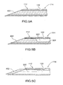
- Figure 5 shows various embodiments of the disposition of stylet 402 within shaft 114. In one embodiment, shown in Figure 5A, stylet 402 may substantially fill the lumen defined by shaft 114.
- stylet 402 may only partially fill the lumen, leaving a luminal space 502 between the exterior surface of a stylet shaft 504 and the interior surface of shaft 114, as shown in Figure 5B.
- Figure 5B shows stylet shaft 504 extending along one side of shaft 114, it should be understood that stylet shaft 504 can be located at any position within shaft 114, for example near the center of shaft 114.
- stylet 402 is in the form of a cap or plug that occludes at least a portion of distal end 424 of shaft 114 and that may be affixed to the distal end of shaft 114, for example by welding, but which does not extend through the length of shaft 114.
- Stylet 402 may be removable from shaft 114, or may be affixed to shaft 114, for example by welding, at one or more locations. Where stylet 402 is positioned such that a luminal space 502 is present, welding stylet 402 to shaft 114 can serve to reduce the radial and axial movement of stylet 402 within shaft 114.
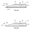
- FIG. 6 shows two exemplary embodiments of a distal region of apparatus 102 comprising a temperature sensor 602, aperture 122 and conductive region 112 (including the conductive regions of shaft 114 and stylet 402 where applicable, as described above).
- Temperature sensor 602 may be welded to the distal end of conductive region 112, for example, either to shaft 114 or to stylet 402.
- temperature sensor 602 is a thermocouple, which may optionally include one or more thermocouple wires running in the lumen of shaft 114 and insulated from elongate shaft 114 and from any other conductive structure electrically coupled to shaft 114 or to power source control unit 106. Insulation may include either insulation on the luminal surface (the surface facing the lumen through which the wire or wires run) of shaft 114 and other conductive structures, or insulation on the outer wall of the wire or wires.
- thermocouple to measure temperature
- conductive region 112 may be a component of thermocouple 602, as follows: the distal end of a thermocouple wire, made of a material that differs from the material of conductive region 112, may be minimally stripped of insulation; temperature sensor 602 may then be formed by welding the distal end of the thermocouple wire to conductive region 112 of shaft 114 to create a thermocouple.
- shaft 114 and conductive region 112 may serve dual purposes, being utilized for energy delivery as well as forming a portion of temperature sensor 602.
- temperature sensor 602 need not comprise a thermocouple, and may comprise a thermistor, thermometer, optical temperature sensor or other temperature sensor.
- apparatus 102 may contain any number of temperature sensors, which may be positioned at a variety of locations along the side of the apparatus, not only at or near conductive region 112, and which may protrude from, be flush with, or be recessed into the surface of elongate shaft 114.
- stylet 402 may be a component of thermocouple 602.
- thermocouple junction 604 is formed by the welding of a wire 606 to stylet 402.
- stylet 402 may be welded or otherwise connected to shaft 114 at some other location of shaft 114.
- stylet 402 may be made of one metal (for example, constantan) and shaft 114 may be made of a dissimilar metal (for example, stainless steel); stylet 402 may then be welded to shaft 114 in order to create a thermocouple junction 608.
- a constantan wire may extend from a proximal end of stylet shaft 504 in order to provide temperature information to power source control unit 106.
- thermocouple junction 608 is shown at a tip of shaft 114, other embodiments may have thermocouple junction 608 at an alternate location along shaft 114.
- more than one temperature sensor may be present on apparatus 102 and any temperature sensor may be a thermocouple, thermistor or other temperature sensing means.
- stylet is used to refer to structure 402 as shown in the various figures, this term is not intended to be exclusive, and is meant to include any occluding means including but not limited to a stylet, obturator and trocar which, in embodiments with an open distal end, at least partially obstructs the distal end of shaft 114, in order to, for example, prevent the passage of tissue into shaft 114.
- an occluding means may comprise an adhesive such as an epoxy resin, wherein the epoxy is positioned so as to occlude at least a portion of the distal end of shaft 114.
- the occluding means may be thermally and/or electrically conductive.
- a stylet into an apparatus of the present invention may be beneficial in that it may facilitate the incorporation of a temperature sensor 602 into apparatus 102 and make the process of manufacturing apparatus 102 more efficient.
- First lumen 706 may be beneficially used as a passage for the injection of a treatment composition.
- the size of lumen 706 and lumen 708 and the number of lumens required may vary depending on the embodiment.
- Another embodiment (not shown) comprises a plurality of lumens, for example as shown in Figure 7C, as well as a stylet housed within one of the lumens.
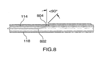
- thermocouple wiring 802 exits the lumen of elongate shaft 114 through a wiring aperture 804.
- Wiring aperture 804 is optionally angled less than 90° with respect to the axis of elongate shaft 114, as shown in Figure 8, in order to minimize bending of wiring 802. Use of this angle provides additional strain relief and protects the insulation of thermocouple wiring 802 as it exits shaft 114, lies parallel to elongate shaft 114, and is covered by insulating coating 118.
- any wires may exit shaft 114 at any angle.
- all wires associated with apparatus 102 may remain within shaft 114 until a proximal end of shaft 114 is reached.
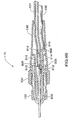
- thermocouple wire 908 may be electrically coupled to a second conductor 910 of electrical cable 138 at solder joint 912, and may enter elongate shaft 114 at a proximal end 914 of shaft 114.
- elements 904 and 912 have been described as crimp and solder joints, respectively, other means of electrical coupling are envisioned for either element as well, including but not limited to soldering, mechanical crimping and welding.
- Flexible tube 124 is coupled to elongate shaft 114 at junction 916 and is slid over proximal end 914. Junction 916 thus helps to provide fluid communication from fluid delivery mechanism 110 to aperture 122.
- a solder joint 918 provides electrical coupling between a first conductor 906 of electrical cable 138 and elongate shaft 114.
- a second thermocouple wire 908 may be electrically coupled to a second conductor 910 of electrical cable 138 at solder joint 912 and may run along shaft 114 beneath insulating coating 118.
- elements 918 and 912 have been described as solder joints, other means of electrical coupling are envisioned as well, including but not limited to mechanical crimping and welding.
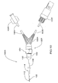
- An apparatus 1000 has a handle 1002 configured to reduce torque.
- Handle 1002 incorporates a "V" shaped housing section 1004 having one arm for coupling to a treatment composition tube 1024 and a second arm for coupling to an electrical cable 1038.
- Treatment composition tube 1024 and electrical cable 1038 extend from the end of handle 1002 and are coupled to fluid delivery interface connection 1026 and electrical connector 1040, respectively, to substantially reduce the force transmitted to a conductive region 112.
- apparatus 1000 in Figure 10 may also comprise a temperature sensor (not shown), an insulating coating 118, an aperture 122, first orientation markings 132 to indicate, for example, 180° rotation, second orientation markings 134 to indicate, for example, 90° rotation, and an aperture marker 130 to indicate a location of aperture 122. It will be understood that the extent to which tube 1024 extends into handle 1002 or onto shaft 1024 can vary so long as it is in fluid communication with an aperture 122.
- Shaft 114 could be made of a conductive material and then coated with an insulating material as in the embodiment shown in Figure 1 or could be made from a non-conductive material such as, but not restricted to, polyetheretherketone (PEEK).
- Conductive region 112 is made of a conductive material and attached to non-conductive shaft 114. There are various methods in which conductive region 112 could be attached to non-conductive shaft 114 including, but not limited to, chemical bonding, press fits and screw fits.
- the wiring for temperature sensor 602 in embodiments comprising a temperature sensor
- the conductive region i.e.
- the wire or other means of transmitting electrical energy from a power source to the conductive region may extend through and along a lumen of shaft 114 and connect to conductive region 112.
- the wiring for one or more of temperature sensor 602 and conductive region 112 may be extruded in the walls of shaft 114 such that the lumen could be used to deliver treatment composition but may not be required to house wiring.
- Conductive region 112 can therefore serve multiple purposes.
- Conductive region 112 can be the site of passage for electric current to the surrounding tissue. It can also be the site for the release of a treatment composition.
- conductive region 112 can also house one or more temperature sensors 602.
- Various tip geometries, such as a bevel on the end of the conductive region with a bottom hole and a mid-bevel temperature sensor are also contemplated embodiments (not shown). It should be understood that various other tip shapes and sizes; aperture sizes and placements, and temperature sensor placements are also considered to be viable options for this invention.
- An electrosurgical apparatus in accordance with the present invention may beneficially be used to treat various disease conditions, including but not limited to chronic back pain.
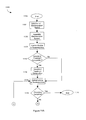
- FIGs 11A and 11B a flowchart of operations 1100, in accordance with one embodiment of a method aspect of the invention, is illustrated.
- the method for using electrosurgical apparatus 102 is initiated.
- an electrosurgical apparatus in accordance with the apparatus aspect of the present invention is selected and obtained for performing the electrosurgical procedure.
- Reference to electrosurgical apparatus 102 of Figure 1 in connection with the method aspect of the invention is intended to be exemplary and illustrative only. Selection may thus include choosing one of an assortment of electrosurgical devices or apparatuses for appropriate dimension, such as length, tip shape, active tip length, gauge, etc.
- the electrosurgical apparatus is positioned in body 104.
- the step of positioning the electrosurgical apparatus may comprise a step of percutaneous insertion of the distal end of apparatus 102 into body 104.
- the step of positioning may further comprise a step of utilizing an aid to precisely position the apparatus.
- a visual, tactile or radiopaque marker may be used to help determine a location of the apparatus within body 104. Visualization may involve the use of fluoroscopic, x-ray or other imaging.
- a user may monitor impedance of tissue as apparatus 102 is inserted through body 104 in order to position the apparatus within a desired tissue region.
- a user may deliver stimulation energy to body 104 in order to ascertain the proximity of apparatus 102 to various neural structures, thus facilitating the placement of apparatus 102 at a desired location within body 104.
- apparatus 102 is inserted to a final placement position in target area 120 of body 104.
- positioning of apparatus 102 at any initial placement location may be performed at step 1108 and positioning of apparatus 102 in a final location may occur later, but before delivering energy at step 1114.
- the apparatus may be positioned at a site associated with a patient's vertebral column, including but not limited to a facet joint.
- the user decides whether or not to administer a treatment composition to body 104.
- the decision to administer treatment composition may include factors such as the preference of the physician, allergic reactions to treatment composition, and/or the delivery of nerve stimulation energy rather than nerve ablation energy.
- the user decides to administer treatment composition fluid and treatment composition fluid is administered via Yes branch to step 1112.
- Administration of treatment composition fluid may include, but is not limited to, injection of sterile water or saline solution to modify electrical properties of a body tissue, injection of local anesthetic solution to block, hinder or change the signal propagation of pain from the body tissue and injection of a dye for visualization of the body tissue.
- treatment fluids or combinations of the abovementioned treatment fluids may be injected into the body tissue surrounding a distal region of apparatus 102.
- step 1110 if the user decides to not administer treatment composition fluid, the user chooses to deliver energy to the treatment area via No branch to step 1114.
- this first embodiment of the method invention comprises the administration of treatment composition fluid at step 1112 prior to delivery of energy to treatment area at step 1114, administration of treatment composition fluid may rather occur during and/or after delivery of energy to treatment area or may not occur at all.
- This monitoring may include, but is not limited to, user comparison of elapsed time while energy is being delivered to body tissue compared to the desired or set time for which delivery of energy to treatment area should occur, user choice to terminate energy delivery, logic in power source control unit 106 to end energy delivery upon detection of a system error during energy delivery, and/or measurement in power source control unit 106 to automatically terminate energy delivery upon elapsed time reaching desired treatment time, which is set on power source control unit 106.
- System errors may include, but are not limited to, detection of discontinuity between electrosurgical apparatus 102 and power source control unit 106, high or low impedance between conductive region 112 and return dispersive electrode 108 and delivered power exceeding power limit.
- energy delivery may be altered depending on feedback from temperature and/or impedance measurements, as described with respect to step 1120 below. If it is determined that energy delivery to the treatment area should be terminated, the procedure is stopped at step 1118 via the Yes branch. If energy delivery to the treatment area is not complete in step 1116, measurements from electrosurgical apparatus 102 at treatment area 120 are monitored manually by the user or automatically by power source control unit 106 at step 1120 ( Figure 8B) via No branch from step 1116.
- temperature measurement of treatment area 120 is monitored at step 1120.
- Monitoring of temperature in treatment area 120 may include, but is not limited to, the measurement of temperature through the use of a temperature sensor, such as a thermocouple or thermistor, feedback to power source control unit 106, and temperature data display on a display or monitor, which may be separate from power source control unit 106.
- temperature of tissue in the treatment area is fed back to power source control unit 106 to be used for decision-making at step 1122.
- the measured temperature (or other measurement) of treatment area 120 is compared against predetermined values. These values may include value ranges, threshold values, individual values, etc.
- the user has the option to administer additional treatment composition fluid via fluid delivery mechanism 110.
- This additional treatment composition may include, but is not limited to, any of the treatment compositions mentioned with respect to step 1112.
- Administration of additional treatment composition fluid may occur at any time before, during, or after energy is being delivered to treatment area.
- Step 1124 may also be the initial delivery of treatment composition to treatment area if the user had decided to not administer treatment composition at step 1110. If the user decides to administer treatment composition at step 1124, additional treatment composition is administered to treatment area via Yes branch to step 1126. With the completion of step 1126, or if the user decides not to administer treatment composition at step 1124, the user and/or power source control unit 106 has the option to modify system 100 settings to control energy being delivered to treatment area at step 1128.
- the option to modify system 100 settings may include, but is not limited to, a user choice to manually change power setting to increase/decrease temperature of treatment area 120, a user choice to increase/decrease set temperature of system to change lesion size, and an automatic change in power setting to control temperature of treatment area 120.
- the user and/or power source control unit 106 decide(s) not to modify system 100 settings to control energy being delivered, energy continues to be delivered to treatment area 120 via No branch at step 1114. If the user decides to manually modify or change the system 100 settings to control energy being delivered to treatment area 120, system settings are manually adjusted via Yes branch to step 1130.
- the power source control unit provides automatic control of energy delivery to treatment area and power source control unit 106 determines that system 100 parameter settings must be adjusted, adjustment occurs automatically via Yes branch to step 1130.
- Automatic control may include the ability of power source control unit 106 to continuously monitor treatment measurements, compare said measurements to acceptable values, ranges, etc., make decisions based on said comparison and modify system parameter settings to obtain acceptable treatment measurements.
- System parameter settings may include, but are not limited to, settings for power, current, voltage, temperature, delivery rates and treatment time.
- Treatment measurements may include, but are not limited to, measurement of impedance, voltage, current, power, temperature, continuity between electrosurgical apparatus 102 and power source control unit and error checking.
- step 1114 energy continues to be delivered to treatment area 120, using the new settings, at step 1114.
- the treatment procedure beneficially continues from step 1114 through to step 1130 until step 1118 is reached.
- the treatment procedure described herein, as well as any equivalents thereof, may provide relief from symptoms of pain by reducing or eliminating the ability of nerves to transmit pain signals to a patient's brain.
Landscapes
- Health & Medical Sciences (AREA)
- Engineering & Computer Science (AREA)
- Life Sciences & Earth Sciences (AREA)
- Biomedical Technology (AREA)
- Animal Behavior & Ethology (AREA)
- Veterinary Medicine (AREA)
- Surgery (AREA)
- Nuclear Medicine, Radiotherapy & Molecular Imaging (AREA)
- Public Health (AREA)
- General Health & Medical Sciences (AREA)
- Plasma & Fusion (AREA)
- Molecular Biology (AREA)
- Medical Informatics (AREA)
- Heart & Thoracic Surgery (AREA)
- Physics & Mathematics (AREA)
- Otolaryngology (AREA)
- Radiology & Medical Imaging (AREA)
- Surgical Instruments (AREA)
Applications Claiming Priority (4)
| Application Number | Priority Date | Filing Date | Title |
|---|---|---|---|
| US10/853,126 US20050267552A1 (en) | 2004-05-26 | 2004-05-26 | Electrosurgical device |
| US853126 | 2004-05-26 | ||
| US11/125,247 US7306596B2 (en) | 2004-05-26 | 2005-05-10 | Multifunctional electrosurgical apparatus |
| US125247 | 2005-05-10 |
Publications (3)
| Publication Number | Publication Date |
|---|---|
| EP1600113A2 true EP1600113A2 (de) | 2005-11-30 |
| EP1600113A3 EP1600113A3 (de) | 2006-01-11 |
| EP1600113B1 EP1600113B1 (de) | 2016-04-13 |
Family
ID=34941446
Family Applications (1)
| Application Number | Title | Priority Date | Filing Date |
|---|---|---|---|
| EP05253202.5A Expired - Lifetime EP1600113B1 (de) | 2004-05-26 | 2005-05-25 | Multifunktionelles, elektrochirurgisches Gerät |
Country Status (2)
| Country | Link |
|---|---|
| US (1) | US7306596B2 (de) |
| EP (1) | EP1600113B1 (de) |
Cited By (3)
| Publication number | Priority date | Publication date | Assignee | Title |
|---|---|---|---|---|
| WO2018156160A1 (en) * | 2017-02-27 | 2018-08-30 | Avent, Inc. | Method and system for improving location accuracy of a radiofrequency ablation procedure via fiducial marking |
| WO2020131769A1 (en) * | 2018-12-21 | 2020-06-25 | Avent, Inc. | Cooled radiofrequency ablation probe |
| US11452562B2 (en) | 2018-12-21 | 2022-09-27 | Avent, Inc. | Dual cooled radiofrequency ablation probes tethered together by electrical and fluid conduits |
Families Citing this family (59)
| Publication number | Priority date | Publication date | Assignee | Title |
|---|---|---|---|---|
| US6558385B1 (en) | 2000-09-22 | 2003-05-06 | Tissuelink Medical, Inc. | Fluid-assisted medical device |
| US8048070B2 (en) | 2000-03-06 | 2011-11-01 | Salient Surgical Technologies, Inc. | Fluid-assisted medical devices, systems and methods |
| US6953461B2 (en) | 2002-05-16 | 2005-10-11 | Tissuelink Medical, Inc. | Fluid-assisted medical devices, systems and methods |
| US6689131B2 (en) | 2001-03-08 | 2004-02-10 | Tissuelink Medical, Inc. | Electrosurgical device having a tissue reduction sensor |
| JP2004500207A (ja) | 2000-03-06 | 2004-01-08 | ティシューリンク・メディカル・インコーポレーテッド | 流体配給システム及び電気外科用器具コントローラ |
| US7811282B2 (en) | 2000-03-06 | 2010-10-12 | Salient Surgical Technologies, Inc. | Fluid-assisted electrosurgical devices, electrosurgical unit with pump and methods of use thereof |
| US7077842B1 (en) * | 2001-08-03 | 2006-07-18 | Cosman Jr Eric R | Over-the-wire high frequency electrode |
| AU2002357166A1 (en) | 2001-12-12 | 2003-06-23 | Tissuelink Medical, Inc. | Fluid-assisted medical devices, systems and methods |
| US6907884B2 (en) | 2002-09-30 | 2005-06-21 | Depay Acromed, Inc. | Method of straddling an intraosseous nerve |
| US8361067B2 (en) | 2002-09-30 | 2013-01-29 | Relievant Medsystems, Inc. | Methods of therapeutically heating a vertebral body to treat back pain |
| US7258690B2 (en) | 2003-03-28 | 2007-08-21 | Relievant Medsystems, Inc. | Windowed thermal ablation probe |
| JP2006504472A (ja) | 2002-10-29 | 2006-02-09 | ティシューリンク・メディカル・インコーポレーテッド | 流体補助電気外科手術鋏及び方法 |
| US7727232B1 (en) | 2004-02-04 | 2010-06-01 | Salient Surgical Technologies, Inc. | Fluid-assisted medical devices and methods |
| US7862563B1 (en) | 2005-02-18 | 2011-01-04 | Cosman Eric R | Integral high frequency electrode |
| WO2007006158A1 (en) * | 2005-07-14 | 2007-01-18 | Baylis Medical Company Inc. | Electrosurgical device and methods |
| EP2289449B1 (de) | 2005-08-02 | 2013-12-25 | Neurotherm, Inc. | Gerät, um zu diagnostizieren und Nervenfunktionsstörung zu behandeln |
| US7976542B1 (en) * | 2006-03-02 | 2011-07-12 | Cosman Eric R | Adjustable high frequency electrode |
| US8103356B2 (en) * | 2006-05-23 | 2012-01-24 | Vertech, Inc. | High frequency epidural neuromodulation catheter without needle for effectuating RF treatment |
| US7875026B1 (en) * | 2007-02-23 | 2011-01-25 | Ellman International, Inc. | Finger-controllable electrosurgical handpiece |
| US8298216B2 (en) | 2007-11-14 | 2012-10-30 | Myoscience, Inc. | Pain management using cryogenic remodeling |
| US20090287140A1 (en) * | 2008-05-16 | 2009-11-19 | Rittman Iii William J | Electrical stimulation and infusion introducer assembly |
| CA2957010C (en) | 2008-09-26 | 2017-07-04 | Relievant Medsystems, Inc. | Systems and methods for navigating an instrument through bone |
| US10028753B2 (en) | 2008-09-26 | 2018-07-24 | Relievant Medsystems, Inc. | Spine treatment kits |
| US20100130976A1 (en) * | 2008-11-21 | 2010-05-27 | Smith & Nephew Inc. | Reducing cross-talk effects in an rf electrosurgical device |
| JP5836964B2 (ja) | 2009-11-05 | 2015-12-24 | ニンバス・コンセプツ・エルエルシー | 脊椎高周波神経切断術のための方法およびシステム |
| US20110129574A1 (en) * | 2009-11-30 | 2011-06-02 | Pathak Chandrashekhar P | Methods and compositions for filling fleshy fruits and vegetables |
| US8641708B2 (en) * | 2009-12-29 | 2014-02-04 | Biosense Webster (Israel), Ltd. | Measuring weak signals over ablation lines |
| US20110224554A1 (en) * | 2010-03-12 | 2011-09-15 | Optomak Inc. | Optogenetic Fiber Optic Cannula and Adapted Fiber Optic Connector |
| MX2012013280A (es) | 2010-05-21 | 2013-03-05 | Nimbus Concepts Llc | Sistema y metodos para ablacion de tejido. |
| US9486275B2 (en) * | 2010-12-30 | 2016-11-08 | Avent, Inc. | Electrosurgical apparatus having a sensor |
| US20120197214A1 (en) * | 2011-02-02 | 2012-08-02 | Mark David Manley | Peripheral nerve blockade device |
| US8939969B2 (en) * | 2011-09-30 | 2015-01-27 | Kimberly-Clark, Inc. | Electrosurgical device with offset conductive element |
| WO2013101772A1 (en) | 2011-12-30 | 2013-07-04 | Relievant Medsystems, Inc. | Systems and methods for treating back pain |
| US10588691B2 (en) | 2012-09-12 | 2020-03-17 | Relievant Medsystems, Inc. | Radiofrequency ablation of tissue within a vertebral body |
| CA2889478C (en) | 2012-11-05 | 2020-11-24 | Relievant Medsystems, Inc. | Systems and methods for creating curved paths through bone and modulating nerves within the bone |
| US10492849B2 (en) | 2013-03-15 | 2019-12-03 | Cynosure, Llc | Surgical instruments and systems with multimodes of treatments and electrosurgical operation |
| WO2014148289A1 (ja) * | 2013-03-22 | 2014-09-25 | 株式会社アドメテック | 生体加熱器具及び制御装置 |
| US9724151B2 (en) | 2013-08-08 | 2017-08-08 | Relievant Medsystems, Inc. | Modulating nerves within bone using bone fasteners |
| US20150073515A1 (en) * | 2013-09-09 | 2015-03-12 | Medtronic Ardian Luxembourg S.a.r.I. | Neuromodulation Catheter Devices and Systems Having Energy Delivering Thermocouple Assemblies and Associated Methods |
| US10643371B2 (en) * | 2014-08-11 | 2020-05-05 | Covidien Lp | Treatment procedure planning system and method |
| RU2017105412A (ru) | 2014-08-26 | 2018-09-27 | Авент, Инк. | Способ и система для нахождения источника хронической боли и ее устранения |
| US10675085B2 (en) | 2015-11-23 | 2020-06-09 | Boston Scientific Scimed, Inc. | Devices and methods for enhanced denervation procedures |
| US12558145B2 (en) | 2016-07-01 | 2026-02-24 | Cynosure, Llc | Non-invasive, uniform and non-uniform RF methods and systems related applications |
| US12376898B2 (en) | 2016-07-01 | 2025-08-05 | Cynosure, Llc | Non-invasive, uniform and non-uniform RF methods and systems related applications |
| WO2018144297A1 (en) | 2017-02-01 | 2018-08-09 | Avent, Inc. | Emg guidance for probe placement, nearby tissue preservation, and lesion confirmation |
| AU2019217623B2 (en) | 2018-02-07 | 2021-10-28 | Cynosure, Inc. | Methods and apparatus for controlled RF treatments and RF generator system |
| GB2579707A (en) | 2018-10-15 | 2020-07-01 | Avent Inc | Compositions, systems, kits, and methods for neural ablation |
| US12114919B2 (en) | 2018-10-24 | 2024-10-15 | Boston Scientific Scimed, Inc. | Movable electrodes for controlled irreversible electroporation ablative volumes |
| US12396786B2 (en) | 2019-03-22 | 2025-08-26 | Stryker Corporation | Systems for ablating tissue |
| EP3941570A4 (de) * | 2019-03-25 | 2022-11-23 | Ennovation, LLC | Neuromodulationskatheter |
| USD1005484S1 (en) | 2019-07-19 | 2023-11-21 | Cynosure, Llc | Handheld medical instrument and docking base |
| EP4027912B1 (de) | 2019-09-12 | 2024-12-18 | Relievant Medsystems, Inc. | Systeme zur gewebemodulation |
| WO2021086817A1 (en) * | 2019-10-28 | 2021-05-06 | Boston Scientific Neuromodulation Corporation | Rf electrode cannula |
| WO2022010817A1 (en) * | 2020-07-06 | 2022-01-13 | Ennovation, Llc | A catheter-through-catheter arrangement of stimulating catheters for providing pain control by nerve block and neuromodulation of peripheral nerves |
| WO2022011115A1 (en) | 2020-07-10 | 2022-01-13 | Relievant Medsystems, Inc. | Vertebral denervation in conjunction with vertebral fusion |
| US12082876B1 (en) | 2020-09-28 | 2024-09-10 | Relievant Medsystems, Inc. | Introducer drill |
| AU2021409967A1 (en) | 2020-12-22 | 2023-08-03 | Relievant Medsystems, Inc. | Prediction of candidates for spinal neuromodulation |
| US12433668B1 (en) | 2021-11-08 | 2025-10-07 | Relievant Medsystems, Inc. | Impedance stoppage mitigation during radiofrequency tissue ablation procedures |
| US12150702B1 (en) | 2024-06-03 | 2024-11-26 | Physcade, Inc. | Generator and catheter for tissue ablation |
Family Cites Families (31)
| Publication number | Priority date | Publication date | Assignee | Title |
|---|---|---|---|---|
| US4311145A (en) | 1979-07-16 | 1982-01-19 | Neomed, Inc. | Disposable electrosurgical instrument |
| US4411266A (en) | 1980-09-24 | 1983-10-25 | Cosman Eric R | Thermocouple radio frequency lesion electrode |
| US5421819A (en) | 1992-08-12 | 1995-06-06 | Vidamed, Inc. | Medical probe device |
| US5275597A (en) * | 1992-05-18 | 1994-01-04 | Baxter International Inc. | Percutaneous transluminal catheter and transmitter therefor |
| US5281218A (en) | 1992-06-05 | 1994-01-25 | Cardiac Pathways Corporation | Catheter having needle electrode for radiofrequency ablation |
| AU4854393A (en) | 1992-09-11 | 1994-04-12 | Advanced Surgical, Inc. | Self-introducing infusion catheter |
| US5342357A (en) | 1992-11-13 | 1994-08-30 | American Cardiac Ablation Co., Inc. | Fluid cooled electrosurgical cauterization system |
| AU686173B2 (en) | 1993-06-10 | 1998-02-05 | Mir A. Imran | Transurethral radio frequency ablation apparatus |
| US5433739A (en) | 1993-11-02 | 1995-07-18 | Sluijter; Menno E. | Method and apparatus for heating an intervertebral disc for relief of back pain |
| US6241725B1 (en) * | 1993-12-15 | 2001-06-05 | Sherwood Services Ag | High frequency thermal ablation of cancerous tumors and functional targets with image data assistance |
| US5609151A (en) | 1994-09-08 | 1997-03-11 | Medtronic, Inc. | Method for R-F ablation |
| AU4252596A (en) | 1994-12-13 | 1996-07-03 | Torben Lorentzen | An electrosurgical instrument for tissue ablation, an apparatus, and a method for providing a lesion in damaged and diseased tissue from a mammal |
| US6602248B1 (en) * | 1995-06-07 | 2003-08-05 | Arthro Care Corp. | Methods for repairing damaged intervertebral discs |
| US5800428A (en) | 1996-05-16 | 1998-09-01 | Angeion Corporation | Linear catheter ablation system |
| US6620155B2 (en) | 1996-07-16 | 2003-09-16 | Arthrocare Corp. | System and methods for electrosurgical tissue contraction within the spine |
| US5893885A (en) | 1996-11-01 | 1999-04-13 | Cordis Webster, Inc. | Multi-electrode ablation catheter |
| US5824007A (en) | 1996-12-03 | 1998-10-20 | Simon Fraser University | Adjustable surgical stand |
| US6547788B1 (en) * | 1997-07-08 | 2003-04-15 | Atrionx, Inc. | Medical device with sensor cooperating with expandable member |
| US6146380A (en) | 1998-01-09 | 2000-11-14 | Radionics, Inc. | Bent tip electrical surgical probe |
| US6315777B1 (en) * | 1998-07-07 | 2001-11-13 | Medtronic, Inc. | Method and apparatus for creating a virtual electrode used for the ablation of tissue |
| US6238393B1 (en) * | 1998-07-07 | 2001-05-29 | Medtronic, Inc. | Method and apparatus for creating a bi-polar virtual electrode used for the ablation of tissue |
| US6123703A (en) * | 1998-09-19 | 2000-09-26 | Tu; Lily Chen | Ablation catheter and methods for treating tissues |
| US6463332B1 (en) | 1999-09-17 | 2002-10-08 | Core Medical, Inc. | Method and system for pericardial enhancement |
| WO2001043653A1 (en) | 1999-12-15 | 2001-06-21 | Edwards Stuart D | Treatment of eustachian tube dysfunction by application of radiofrequency energy |
| US8048070B2 (en) | 2000-03-06 | 2011-11-01 | Salient Surgical Technologies, Inc. | Fluid-assisted medical devices, systems and methods |
| US6805695B2 (en) * | 2000-04-04 | 2004-10-19 | Spinalabs, Llc | Devices and methods for annular repair of intervertebral discs |
| US20030158545A1 (en) | 2000-09-28 | 2003-08-21 | Arthrocare Corporation | Methods and apparatus for treating back pain |
| US6921399B2 (en) | 2001-11-02 | 2005-07-26 | Electrosurgery Associates, Llc | High efficiency electrosurgery probe |
| US7588568B2 (en) | 2002-07-19 | 2009-09-15 | Biosense Webster, Inc. | Atrial ablation catheter and method for treating atrial fibrillation |
| US6730079B2 (en) * | 2002-07-22 | 2004-05-04 | Medtronic Vidamed, Inc. | Method for calculating impedance and apparatus utilizing same |
| WO2005048862A2 (en) * | 2003-11-18 | 2005-06-02 | Scimed Life Systems, Inc. | System and method for tissue ablation |
-
2005
- 2005-05-10 US US11/125,247 patent/US7306596B2/en not_active Expired - Lifetime
- 2005-05-25 EP EP05253202.5A patent/EP1600113B1/de not_active Expired - Lifetime
Non-Patent Citations (1)
| Title |
|---|
| None |
Cited By (5)
| Publication number | Priority date | Publication date | Assignee | Title |
|---|---|---|---|---|
| WO2018156160A1 (en) * | 2017-02-27 | 2018-08-30 | Avent, Inc. | Method and system for improving location accuracy of a radiofrequency ablation procedure via fiducial marking |
| WO2020131769A1 (en) * | 2018-12-21 | 2020-06-25 | Avent, Inc. | Cooled radiofrequency ablation probe |
| US11452562B2 (en) | 2018-12-21 | 2022-09-27 | Avent, Inc. | Dual cooled radiofrequency ablation probes tethered together by electrical and fluid conduits |
| US11690668B2 (en) | 2018-12-21 | 2023-07-04 | Avent, Inc. | Cooled radiofrequency ablation probe |
| AU2019403083B2 (en) * | 2018-12-21 | 2024-11-21 | Avent, Inc. | Cooled radiofrequency ablation probe |
Also Published As
| Publication number | Publication date |
|---|---|
| US20050267465A1 (en) | 2005-12-01 |
| EP1600113B1 (de) | 2016-04-13 |
| US7306596B2 (en) | 2007-12-11 |
| EP1600113A3 (de) | 2006-01-11 |
Similar Documents
| Publication | Publication Date | Title |
|---|---|---|
| US7306596B2 (en) | Multifunctional electrosurgical apparatus | |
| US8187268B2 (en) | Electrosurgical apparatus having a temperature sensor | |
| US10327839B2 (en) | Electrosurgical apparatus having a sensor | |
| US20050267552A1 (en) | Electrosurgical device | |
| EP1863558B1 (de) | Elektrochirurgische kanüle | |
| CA2849006C (en) | Electrosurgical device with offset conductive element | |
| US20220023588A1 (en) | Catheter system | |
| US7593778B2 (en) | Electrosurgical device with improved visibility | |
| CA3093398C (en) | Systems and methods for creating curved paths through bone and modulating nerves within the bone | |
| PT1786346E (pt) | Sistema electrocirúrgico bipolar | |
| AU2023222938B2 (en) | Method and system for improving location accuracy of a radiofrequency ablation procedure via fiducial marking | |
| AU2011350059B2 (en) | Electrosurgical apparatus having a sensor |
Legal Events
| Date | Code | Title | Description |
|---|---|---|---|
| PUAI | Public reference made under article 153(3) epc to a published international application that has entered the european phase |
Free format text: ORIGINAL CODE: 0009012 |
|
| PUAL | Search report despatched |
Free format text: ORIGINAL CODE: 0009013 |
|
| AK | Designated contracting states |
Kind code of ref document: A2 Designated state(s): AT BE BG CH CY CZ DE DK EE ES FI FR GB GR HU IE IS IT LI LT LU MC NL PL PT RO SE SI SK TR |
|
| AX | Request for extension of the european patent |
Extension state: AL BA HR LV MK YU |
|
| AK | Designated contracting states |
Kind code of ref document: A3 Designated state(s): AT BE BG CH CY CZ DE DK EE ES FI FR GB GR HU IE IS IT LI LT LU MC NL PL PT RO SE SI SK TR |
|
| AX | Request for extension of the european patent |
Extension state: AL BA HR LV MK YU |
|
| 17P | Request for examination filed |
Effective date: 20060221 |
|
| AKX | Designation fees paid |
Designated state(s): AT BE BG CH CY CZ DE DK EE ES FI FR GB GR HU IE IS IT LI LT LU MC NL PL PT RO SE SI SK TR |
|
| 17Q | First examination report despatched |
Effective date: 20070529 |
|
| RAP1 | Party data changed (applicant data changed or rights of an application transferred) |
Owner name: KIMBERLY-CLARK INC. |
|
| RAP1 | Party data changed (applicant data changed or rights of an application transferred) |
Owner name: AVENT, INC. |
|
| GRAP | Despatch of communication of intention to grant a patent |
Free format text: ORIGINAL CODE: EPIDOSNIGR1 |
|
| INTG | Intention to grant announced |
Effective date: 20151207 |
|
| GRAS | Grant fee paid |
Free format text: ORIGINAL CODE: EPIDOSNIGR3 |
|
| GRAA | (expected) grant |
Free format text: ORIGINAL CODE: 0009210 |
|
| AK | Designated contracting states |
Kind code of ref document: B1 Designated state(s): AT BE BG CH CY CZ DE DK EE ES FI FR GB GR HU IE IS IT LI LT LU MC NL PL PT RO SE SI SK TR |
|
| REG | Reference to a national code |
Ref country code: GB Ref legal event code: FG4D |
|
| REG | Reference to a national code |
Ref country code: AT Ref legal event code: REF Ref document number: 789221 Country of ref document: AT Kind code of ref document: T Effective date: 20160415 Ref country code: CH Ref legal event code: EP |
|
| REG | Reference to a national code |
Ref country code: IE Ref legal event code: FG4D |
|
| REG | Reference to a national code |
Ref country code: DE Ref legal event code: R096 Ref document number: 602005048936 Country of ref document: DE |
|
| REG | Reference to a national code |
Ref country code: FR Ref legal event code: PLFP Year of fee payment: 12 |
|
| REG | Reference to a national code |
Ref country code: NL Ref legal event code: FP |
|
| REG | Reference to a national code |
Ref country code: LT Ref legal event code: MG4D |
|
| PG25 | Lapsed in a contracting state [announced via postgrant information from national office to epo] |
Ref country code: BE Free format text: LAPSE BECAUSE OF NON-PAYMENT OF DUE FEES Effective date: 20160531 |
|
| REG | Reference to a national code |
Ref country code: AT Ref legal event code: MK05 Ref document number: 789221 Country of ref document: AT Kind code of ref document: T Effective date: 20160413 |
|
| PG25 | Lapsed in a contracting state [announced via postgrant information from national office to epo] |
Ref country code: PL Free format text: LAPSE BECAUSE OF FAILURE TO SUBMIT A TRANSLATION OF THE DESCRIPTION OR TO PAY THE FEE WITHIN THE PRESCRIBED TIME-LIMIT Effective date: 20160413 Ref country code: FI Free format text: LAPSE BECAUSE OF FAILURE TO SUBMIT A TRANSLATION OF THE DESCRIPTION OR TO PAY THE FEE WITHIN THE PRESCRIBED TIME-LIMIT Effective date: 20160413 Ref country code: LT Free format text: LAPSE BECAUSE OF FAILURE TO SUBMIT A TRANSLATION OF THE DESCRIPTION OR TO PAY THE FEE WITHIN THE PRESCRIBED TIME-LIMIT Effective date: 20160413 |
|
| PG25 | Lapsed in a contracting state [announced via postgrant information from national office to epo] |
Ref country code: PT Free format text: LAPSE BECAUSE OF FAILURE TO SUBMIT A TRANSLATION OF THE DESCRIPTION OR TO PAY THE FEE WITHIN THE PRESCRIBED TIME-LIMIT Effective date: 20160816 Ref country code: ES Free format text: LAPSE BECAUSE OF FAILURE TO SUBMIT A TRANSLATION OF THE DESCRIPTION OR TO PAY THE FEE WITHIN THE PRESCRIBED TIME-LIMIT Effective date: 20160413 Ref country code: SE Free format text: LAPSE BECAUSE OF FAILURE TO SUBMIT A TRANSLATION OF THE DESCRIPTION OR TO PAY THE FEE WITHIN THE PRESCRIBED TIME-LIMIT Effective date: 20160413 Ref country code: AT Free format text: LAPSE BECAUSE OF FAILURE TO SUBMIT A TRANSLATION OF THE DESCRIPTION OR TO PAY THE FEE WITHIN THE PRESCRIBED TIME-LIMIT Effective date: 20160413 Ref country code: GR Free format text: LAPSE BECAUSE OF FAILURE TO SUBMIT A TRANSLATION OF THE DESCRIPTION OR TO PAY THE FEE WITHIN THE PRESCRIBED TIME-LIMIT Effective date: 20160714 |
|
| PG25 | Lapsed in a contracting state [announced via postgrant information from national office to epo] |
Ref country code: BE Free format text: LAPSE BECAUSE OF FAILURE TO SUBMIT A TRANSLATION OF THE DESCRIPTION OR TO PAY THE FEE WITHIN THE PRESCRIBED TIME-LIMIT Effective date: 20160413 |
|
| REG | Reference to a national code |
Ref country code: CH Ref legal event code: PL |
|
| REG | Reference to a national code |
Ref country code: DE Ref legal event code: R097 Ref document number: 602005048936 Country of ref document: DE |
|
| PG25 | Lapsed in a contracting state [announced via postgrant information from national office to epo] |
Ref country code: DK Free format text: LAPSE BECAUSE OF FAILURE TO SUBMIT A TRANSLATION OF THE DESCRIPTION OR TO PAY THE FEE WITHIN THE PRESCRIBED TIME-LIMIT Effective date: 20160413 Ref country code: MC Free format text: LAPSE BECAUSE OF FAILURE TO SUBMIT A TRANSLATION OF THE DESCRIPTION OR TO PAY THE FEE WITHIN THE PRESCRIBED TIME-LIMIT Effective date: 20160413 Ref country code: RO Free format text: LAPSE BECAUSE OF FAILURE TO SUBMIT A TRANSLATION OF THE DESCRIPTION OR TO PAY THE FEE WITHIN THE PRESCRIBED TIME-LIMIT Effective date: 20160413 Ref country code: CZ Free format text: LAPSE BECAUSE OF FAILURE TO SUBMIT A TRANSLATION OF THE DESCRIPTION OR TO PAY THE FEE WITHIN THE PRESCRIBED TIME-LIMIT Effective date: 20160413 Ref country code: LI Free format text: LAPSE BECAUSE OF NON-PAYMENT OF DUE FEES Effective date: 20160531 Ref country code: EE Free format text: LAPSE BECAUSE OF FAILURE TO SUBMIT A TRANSLATION OF THE DESCRIPTION OR TO PAY THE FEE WITHIN THE PRESCRIBED TIME-LIMIT Effective date: 20160413 Ref country code: CH Free format text: LAPSE BECAUSE OF NON-PAYMENT OF DUE FEES Effective date: 20160531 Ref country code: SK Free format text: LAPSE BECAUSE OF FAILURE TO SUBMIT A TRANSLATION OF THE DESCRIPTION OR TO PAY THE FEE WITHIN THE PRESCRIBED TIME-LIMIT Effective date: 20160413 |
|
| PLBE | No opposition filed within time limit |
Free format text: ORIGINAL CODE: 0009261 |
|
| STAA | Information on the status of an ep patent application or granted ep patent |
Free format text: STATUS: NO OPPOSITION FILED WITHIN TIME LIMIT |
|
| REG | Reference to a national code |
Ref country code: IE Ref legal event code: MM4A |
|
| 26N | No opposition filed |
Effective date: 20170116 |
|
| REG | Reference to a national code |
Ref country code: FR Ref legal event code: PLFP Year of fee payment: 13 |
|
| PG25 | Lapsed in a contracting state [announced via postgrant information from national office to epo] |
Ref country code: SI Free format text: LAPSE BECAUSE OF FAILURE TO SUBMIT A TRANSLATION OF THE DESCRIPTION OR TO PAY THE FEE WITHIN THE PRESCRIBED TIME-LIMIT Effective date: 20160413 Ref country code: IE Free format text: LAPSE BECAUSE OF NON-PAYMENT OF DUE FEES Effective date: 20160525 |
|
| REG | Reference to a national code |
Ref country code: FR Ref legal event code: PLFP Year of fee payment: 14 |
|
| PG25 | Lapsed in a contracting state [announced via postgrant information from national office to epo] |
Ref country code: HU Free format text: LAPSE BECAUSE OF FAILURE TO SUBMIT A TRANSLATION OF THE DESCRIPTION OR TO PAY THE FEE WITHIN THE PRESCRIBED TIME-LIMIT; INVALID AB INITIO Effective date: 20050525 Ref country code: CY Free format text: LAPSE BECAUSE OF FAILURE TO SUBMIT A TRANSLATION OF THE DESCRIPTION OR TO PAY THE FEE WITHIN THE PRESCRIBED TIME-LIMIT Effective date: 20160413 |
|
| PG25 | Lapsed in a contracting state [announced via postgrant information from national office to epo] |
Ref country code: LU Free format text: LAPSE BECAUSE OF NON-PAYMENT OF DUE FEES Effective date: 20160525 Ref country code: IS Free format text: LAPSE BECAUSE OF FAILURE TO SUBMIT A TRANSLATION OF THE DESCRIPTION OR TO PAY THE FEE WITHIN THE PRESCRIBED TIME-LIMIT Effective date: 20160413 Ref country code: TR Free format text: LAPSE BECAUSE OF FAILURE TO SUBMIT A TRANSLATION OF THE DESCRIPTION OR TO PAY THE FEE WITHIN THE PRESCRIBED TIME-LIMIT Effective date: 20160413 |
|
| PGFP | Annual fee paid to national office [announced via postgrant information from national office to epo] |
Ref country code: NL Payment date: 20180426 Year of fee payment: 14 |
|
| PG25 | Lapsed in a contracting state [announced via postgrant information from national office to epo] |
Ref country code: BG Free format text: LAPSE BECAUSE OF FAILURE TO SUBMIT A TRANSLATION OF THE DESCRIPTION OR TO PAY THE FEE WITHIN THE PRESCRIBED TIME-LIMIT Effective date: 20160413 |
|
| PGFP | Annual fee paid to national office [announced via postgrant information from national office to epo] |
Ref country code: GR Payment date: 20180625 Year of fee payment: 17 |
|
| REG | Reference to a national code |
Ref country code: NL Ref legal event code: MM Effective date: 20190601 |
|
| PG25 | Lapsed in a contracting state [announced via postgrant information from national office to epo] |
Ref country code: IT Free format text: LAPSE BECAUSE OF NON-PAYMENT OF DUE FEES Effective date: 20190525 Ref country code: NL Free format text: LAPSE BECAUSE OF NON-PAYMENT OF DUE FEES Effective date: 20190601 |
|
| REG | Reference to a national code |
Ref country code: DE Ref legal event code: R082 Ref document number: 602005048936 Country of ref document: DE |
|
| REG | Reference to a national code |
Ref country code: FR Ref legal event code: PLFP Year of fee payment: 19 |
|
| P01 | Opt-out of the competence of the unified patent court (upc) registered |
Effective date: 20230518 |
|
| PGFP | Annual fee paid to national office [announced via postgrant information from national office to epo] |
Ref country code: FR Payment date: 20240328 Year of fee payment: 20 |
|
| PGFP | Annual fee paid to national office [announced via postgrant information from national office to epo] |
Ref country code: GB Payment date: 20240402 Year of fee payment: 20 |
|
| PGFP | Annual fee paid to national office [announced via postgrant information from national office to epo] |
Ref country code: DE Payment date: 20240328 Year of fee payment: 20 |
|
| REG | Reference to a national code |
Ref country code: DE Ref legal event code: R071 Ref document number: 602005048936 Country of ref document: DE |
|
| REG | Reference to a national code |
Ref country code: GB Ref legal event code: PE20 Expiry date: 20250524 |
|
| PG25 | Lapsed in a contracting state [announced via postgrant information from national office to epo] |
Ref country code: GB Free format text: LAPSE BECAUSE OF EXPIRATION OF PROTECTION Effective date: 20250524 |