EP1599848B1 - Schwimmbecken-überwachungssystem - Google Patents
Schwimmbecken-überwachungssystem Download PDFInfo
- Publication number
- EP1599848B1 EP1599848B1 EP04756937A EP04756937A EP1599848B1 EP 1599848 B1 EP1599848 B1 EP 1599848B1 EP 04756937 A EP04756937 A EP 04756937A EP 04756937 A EP04756937 A EP 04756937A EP 1599848 B1 EP1599848 B1 EP 1599848B1
- Authority
- EP
- European Patent Office
- Prior art keywords
- electrical signal
- time periods
- pool
- trigger
- band
- Prior art date
- Legal status (The legal status is an assumption and is not a legal conclusion. Google has not performed a legal analysis and makes no representation as to the accuracy of the status listed.)
- Expired - Lifetime
Links
Images


Classifications
-
- G—PHYSICS
- G08—SIGNALLING
- G08B—SIGNALLING SYSTEMS, e.g. PERSONAL CALLING SYSTEMS; ORDER TELEGRAPHS; ALARM SYSTEMS
- G08B29/00—Checking or monitoring of signalling or alarm systems; Prevention or correction of operating errors, e.g. preventing unauthorised operation
- G08B29/18—Prevention or correction of operating errors
- G08B29/185—Signal analysis techniques for reducing or preventing false alarms or for enhancing the reliability of the system
-
- G—PHYSICS
- G08—SIGNALLING
- G08B—SIGNALLING SYSTEMS, e.g. PERSONAL CALLING SYSTEMS; ORDER TELEGRAPHS; ALARM SYSTEMS
- G08B21/00—Alarms responsive to a single specified undesired or abnormal condition and not otherwise provided for
- G08B21/02—Alarms for ensuring the safety of persons
- G08B21/08—Alarms for ensuring the safety of persons responsive to the presence of persons in a body of water, e.g. a swimming pool; responsive to an abnormal condition of a body of water
- G08B21/082—Alarms for ensuring the safety of persons responsive to the presence of persons in a body of water, e.g. a swimming pool; responsive to an abnormal condition of a body of water by monitoring electrical characteristics of the water
Definitions
- swimming pools can be a hazard when left unattended-
- Some swimming pool monitoring systems sound an alarm when an unauthorized or accidental entry of an object or individual into a pool occurs.
- Some systems use water pressure measurement devices in conjunction with diaphragms to detect the pressure differential in the water due to movement of the water.
- Other systems use infrared or acoustic sensors to detect movement of the water.
- an electronic circuit incorporating probes spaced apart above the water can detect a momentary splash.
- Other systems use a transmitter, for example, worn on a child to set off an alarm if the child enters the water.
- FR 2 763 684 teaches a detection device detecting a person falling into a pool.
- a detector is provided for detecting water waves. Signals of periodic water waves are suppressed. Alarm is given in case of aperiodic water waves.
- US 5,903,218 uses a wave motion detector system for detecting a person falling into a pool.
- the system applies a transducer placed in the water and a filtering element to attenuate frequencies above 2 Hz and below 1 Hz of signals detected by a transducer. If the filtered signal exceed a threshold value an alarm signal is generated.
- a pool monitoring system includes a hydrophone configured to generate an electrical signal in response to receiving a sound pressure wave in the liquid of a pool, and a processor configured to receive the electrical signal and generate a trigger signal, when the electrical signal includes a characteristic signature associated with entry of an object into the liquid of the pool over a time period within a predetermined range of time periods.
- the characteristic signature includes a first frequency component, contained in a frequency spectrum of the electrical signal, within a low band with a magnitude above the trigger level, and a second frequency component, contained in the frequency spectrum, within a high band with a magnitude above the trigger level.
- the low band includes a continuous band of frequencies that is a subset of the range 500 Hz to 2 kHz.
- the high band includes a continuous band of frequencies that is a subset of the range 2.5 kHz to 5 kHz.
- Implementations of the invention may include one or more of the following features.
- the processor is configured to determine a trigger level from a background noise level by setting a gain of an electrical circuit based on background noise in the electrical signal.
- the predetermined range of time periods consists of time periods less than 4 seconds and greater than 0.5 seconds.
- the system can also include a first filter configured to pass the first component if the first component is within the low band, and a second filter configured to pass the second component if the second component is within the high band.
- the first filter and the second filter can be electrical circuits.
- the electrical signal can be digitized
- the frequency spectrum can be calculated based on the digitized electrical signal
- the first filter and the second filter can include processor instructions that operate on the calculated frequency spectrum.
- the hydrophone comprises a piezo-electric material composed of lead zirconate titanate ceramic or polyvinylidene fluoride polymer film.
- the system can also include a poolside horn configured to generate a sound in response to the trigger signal, a first antenna configured to periodically send radio-frequency status signals, one or more monitor units which include a second antenna configured to receive the radio-frequency status signals, and a monitor horn configured to generate a sound in response to the trigger signal.
- the monitor units are configured to indicate reception of the radio-frequency status signals.
- a pool intrusion detection method includes generating an electrical signal in response to receiving a sound pressure wave in the liquid of a pool, and generating a trigger signal in response to receiving the electrical signal when the electrical signal includes a characteristic signature associated with entry of an object into the liquid of the pool over a time period within a predetermined range of time periods.
- the characteristic signature is defined according to the first aspect of the invention.
- Implementations of the invention may include one or more of the following features.
- the pool intrusion detection method can include storing a count of false alarms.
- the false alarms include receiving the electrical signal when the electrical signal includes a noise signature that is different from the characteristic signature, or receiving the electrical signal when the electrical signal includes a noise signature over a time periods that is not within the predetermined range of time periods.
- the pool intrusion detection method can also include adjusting the trigger level in response to the count of false alarms increasing above a predetermined number, or adjusting the center frequencies of the low band and the high band in response to the count of false alarms increasing above a predetermined number.
- the pool monitoring system is capable of distinguishing between movement in the water caused by noise, such as wind or rain, and movement in the water due to entry of an object into the water, such as a person.
- the pool monitoring system is capable of distinguishing between entry into the water of an object such as a person, and entry into the water of objects such as leaves or branches.
- FIG. 1 shows a typical swimming pool environment with a pool monitoring system installed.
- the pool monitoring system includes a poolside unit 20 having a hydrophone 124 (FIG. 10) which is positioned under the water within a swimming pool 15.
- the hydrophone 124 generates an electrical signal in response to sound pressure waves present in the pool.
- This electrical signal is processed by signal processing electronics within the poolside unit 20 to determine the presence of signal characteristics indicating that an intrusion event has occurred in the pool.
- the signal processing electronics uses both frequency spectrum and time domain analysis to differentiate false alarm noise sources from actual intrusion events.
- the poolside unit 20 contains an audible alarm circuit which is activated when an intrusion event is detected.
- the poolside unit 20 also communicates to one or more monitor units 21 via radio-frequency (RF) signals.
- An RF transmitter in the poolside unit 20 sends information to an RF receiver in the monitor unit 21 positioned, for example, in a house 17 proximal to pool 15. This information is processed in the monitor unit 21 and used to control the audible alarm circuit in the monitor unit 21 which is activated when an intrusion event is detected.
- the monitor unit 21 also contains indicators for the status of other system functions such as battery condition and self-test results.
- the poolside unit 20 is battery powered.
- the monitor unit 21 is powered by an AC power line and includes a battery back-up function in the event of AC power failure.
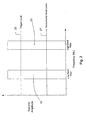
- FIG. 2 shows pass bands of two bandpass filters used by the signal processing electronics to detect an intrusion event.
- the pass band 22 of a low band filter has a center frequency within the range of 500 Hz to 2 kHz.
- the pass band 23 of a high band filter has a center frequency within the range of 2.5 kHz to 5 kHz.
- the signal processing electronics in the poolside unit 20 includes a processor (e.g., a microprocessor) that determines a trigger level 25 that is above a background noise level 27 for both bandpass filters.
- the processor determines that a candidate electrical signal corresponds to a possible intrusion event when the spectral amplitude of the candidate electrical signal is simultaneously above the trigger level for frequencies within the low pass band 22 and for frequencies within the high pass band 23. If a candidate electrical signal qualifies as a possible intrusion event by having this characteristic signature, the processor tests the time envelope of the candidate electrical signal to determine whether the possible intrusion event is a valid intrusion event.
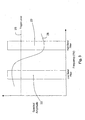
- FIG. 3 shows a typical electrical signal spectral amplitude for a noise event 28 dominated by low frequencies.
- Such events include wind, pump noises and footfall sounds. These are false alarm sounds which do not correspond to an intrusion event because the spectral amplitude registered by the high frequency bandpass filter is below the trigger level 25.
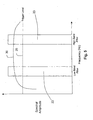
- FIG. 4 shows a typical electrical signal spectral amplitude for a noise event 29 dominated by high frequencies.
- Such events include rain and light weight objects such as a beach ball falling into the pool. These are false alarm sounds which do not correspond to an intrusion event because the spectral amplitude registered by the low frequency bandpass filter is below the trigger level 25.
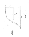
- FIG. 5 shows a typical electrical signal spectral amplitude for a possible intrusion event.
- the spectral amplitude registered by both bandpass filters is above the trigger level 25.
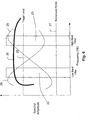
- FIG. 6 combines the plots of spectral amplitudes from FIGS. 3-5 to illustrate the differences between the false alarm event frequency spectra and a possible intrusion event frequency spectrum.
- a candidate electrical signal After a candidate electrical signal has been qualified as a possible intrusion event, by virtue of the spectral amplitude of the candidate electrical signal being above the trigger level for frequencies within the low pass band 22 and frequencies within the high pass band 23, the candidate electrical signal is further tested in a "time envelope test."
- a valid intrusion event presents a wideband signal (according to the characteristic signature described above) which is above the trigger level at both low and high bands for a time period that is within a predetermined range of time period (e.g., 1-2 seconds).
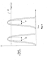
- FIG. 7 shows signal amplitudes for filtered spectral components of a candidate electrical signal as a function of time.
- a signal amplitude 40 of a spectral component within the low passband 22 and a signal amplitude 41 of a spectral component within the high passband 23 are both above the trigger level 25 over a time period 42 (as measured by the processor).
- the candidate electrical signal corresponds to a valid intrusion event if the time period 42 is within the predetermined range of 1-2 seconds.
- FIG. 8 shows signal amplitudes for a series of two impulse events which do not satisfy the minimum time period for a valid intrusion event.
- the time period 50 over which the first impulse event has both low and high spectral components over the trigger level 25, and the time period 51 over which the second impulse event has both low and high spectral components over the trigger level 25 are each less than 1 second.
- FIG. 9 shows signal amplitudes for a long-term noise source which has spectral components that exceed the 2 second maximum time period for a valid intrusion event.
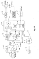
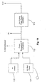
- FIG. 10 is a block diagram of an implementation of poolside unit 20.
- Sound pressure waves in the liquid of the pool are converted to electrical signals by a hydrophone 124.
- the hydrophone is constructed using a ceramic piezoelectric material such as lead zirconate titanate (PVT) or a piezoelectric polymer film such as polyvinylidene fluoride (PVDF).
- An electrical signal from the hydrophone is amplified by preamp 125.
- the preamp 125 is implemented using integrated circuit (IC) operational amplifier technology.
- the preamp 125 provides a voltage gain of between 200 and 2000 as appropriate for the choice of hydrophone 124.
- Two single pole RC filters are used to bandwidth limit the signal.
- a high pass filter with a pole at 20 Hz is formed using a resistor 126 and the capacitance of the hydrophone 124.
- a low pass filter 127 with a pole at 10 kHz, is formed using a capacitor and the preamp 125 feedback resistor.
- the electrical signal is processed next by a programmable gain amplifier 128.
- This amplifier provides an adjustable gain of from 1 to 50 controlled by a microprocessor 131. By this mechanism, the overall sensitivity of the poolside unit 20 can be adjusted by software in the microprocessor 131 in response to changing conditions in the ambient noise level present in the pool.
- the microprocessor 131 is the control mechanism for the poolside unit 20. Via software instructions, the microprocessor 131 sets the gain of the programmable gain amplifier 128 and sets the center frequencies of the two bandpass filters 129 and 130.
- the bandpass filters are implemented by switched capacitor filter integrated circuits.
- the high band filter 129 is a 4th order filter with a center frequency in the range 2.5 kHz to 5 kHz.
- the low band filter 130 is a 4th order filter with a center frequency in the range 500 Hz to 2 kHz.
- the outputs of the filters are converted from analog voltage levels to digital values by an analog-to-digital converter (ADC) 132.
- ADC analog-to-digital converter
- Software instructions executed by the microprocessor 131 accumulate the digital values from the ADC 132 and calculate the root mean square (RMS) amplitude of a high pass filtered electrical signal spectral component and a low pass filtered signal spectral component.
- the microprocessor 131 uses the calculated RMS amplitudes of these low band and high band spectral components to detect the characteristic signature described above.
- the microprocessor 131 also performs the time envelope testing of a candidate electrical signal.
- the microprocessor 131 When a valid intrusion event is detected, the microprocessor 131 sounds an audible alarm by triggering an alarm IC 133.
- the alarm IC 133 for example, is of the type used in smoke detectors.
- the alarm IC drives a piezo horn 134 to produce a loud audible sound.
- the microprocessor 131 communicates to the monitor unit 21 (located, for example, in a house by the pool) via an RF transmitter 135.
- other information about the state of the poolside unit 20 can be communicated to the monitor unit 21 using the RF transmitter 135 and antenna 136. This information can include the state of a battery 139 that powers the poolside unit 20, the results of self-test operations performed by the microprocessor 131, and a periodic "heart-beat" transmission to test the communications link.
- a water sensor 137 informs the microprocessor 131 when the poolside unit 20 enters the water or leaves the water. This allows the microprocessor 131 to place the poolside unit 20 in a low power "sleep" mode to preserve battery life when the unit is not in the pool and therefore not in use.
- the raw signal level from the programmable gain amplifier 128 is also made available to the microprocessor 131 via the microprocessor's interrupt mechanism 138. This signal is used by the microprocessor to reduce power consumption when the raw signal level is below a threshold value.
- the poolside unit 20 is powered by the battery 139. Operating voltage for the various integrated circuits is generated by switched mode power supply 140.
- a block diagram of alternative implementation of the poolside unit 20 is shown in FIG. 11. In this implementation, the output of a preamp 141 is presented directly to an ADC 142.
- Processor instructions are used to implement various software modules for the poolside unit 20.
- a low pass filter module 143 and a high pass filter module 144 are implemented as infinite impulse response (IIR) filters operating on the digital values output by the ADC 142.
- the processor calculates the RMS signal magnitude for the low pass module 143 in magnitude module 145, and for the high pass module 144 in a magnitude module 146.
- a dual threshold module 47 performs characteristic signature testing based on level parameters and an envelope detector 148 performs time envelope testing based on time parameters, as described above.
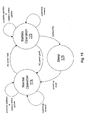
- FIG. 12 is a state transition diagram showing the operation of the poolside unit 20.
- processor instructions initialize the hardware in an initialize state 150 and the unit 20 enters the main processing loop state 151.
- This loop responds to external events via the microprocessor's interrupt mechanism and by polling hardware status registers.
- a periodic timer interrupt which occurs approximately every two minutes, is used to transition to an RF update state 153, trigger an RF transmission to the monitor unit 21, and return to the main loop state 151.
- This regular transmission enables the monitor unit 21 to report when the poolside unit 20 is not active using a timeout mechanism in the monitor unit 21.
- the RF update state 153 is also entered whenever the main loop senses a change in the alarm status, the poolside battery status, or the self-test result.
- a sound pressure wave in the pool of sufficient magnitude will trigger the unit to enter state filter state 155 where the processor tests the outputs of the two bandpass filters for the characteristic signature and performs time envelope testing. Detection of a valid intrusion event will cause the alarm to be sounded in an alarm state 156. A false alarm will be counted in a false alarm state 157.
- the processor counts the number of false alarms that occur between RF updates. If a maximum false alarm threshold is exceeded, a calibration state 158 will be entered. In the calibration state 158, the processor adjusts the sensitivity of the poolside unit 20 by controlling the gain setting of the programmable gain amplifier. The poolside unit 20 will also enter the calibration state 158 if a calibrate button is pressed.
- a self-test state 154 is entered every 30 minutes via a timer interrupt. In this state the processor executes instructions which use the programmable gain amplifier and the analog-to-digital converter to test the sensitivity of the system to ambient sound levels in the pool and insure that the bandpass filters are working properly. The results of the self-test are reported to the monitor unit 21 over the RF link.
- the water sensor will cause the poolside unit 20 to enter the stop state 152. This is a power down condition.
- the processor is notified via a reset interrupt and resumes processing from the initialization state 150. If a reset button is pressed, the poolside unit 20 enters the initialization state 150.
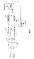
- FIG. 13 is a block diagram of an implementation of the monitor unit 21.
- a microprocessor 160 controls the operation of the monitor unit 21.
- the inputs for the monitor unit 21 come from an RF receiver circuit 163 and a power supply circuit 165.
- the RF receiver 163 receives data from the poolside unit 20 about the status of the poolside alarm, the results of the most recent poolside self-test, and the status of the poolside battery.
- An RF address switch 164 provides protection from RF interference by decoding a unique 10 bit address value which is sent by the poolside unit as a preamble to each data transfer.
- the power supply circuit 165 informs the processor when the monitor unit 21 is running on battery backup so that the monitor software can enter a power conserving state.
- the microprocessor 160 controls status LEDs 161 and a monitor alarm circuit 162 via its digital outputs.
- the status LEDs 161 reflect the alarm state, the condition of both the poolside and monitor batteries, the result of the most recent poolside self-test, and the status of the communications link between the poolside unit 20 and the monitor unit 21.
- the monitor unit 21 receives the data which drives the status LEDs from the poolside unit via the RF signal received by the RF receiver 163.
- Monitor battery status is derived from a voltage comparator within the monitor unit 21.
- FIG. 14 shows a block diagram of an implementation of the monitor unit power supply 165.
- the monitor unit 21 is primarily powered from an AC line by a 9V DC wall plug mounted power supply 171. In the event of an AC power failure, the unit 21 is powered by a 9V battery 170 housed within the unit 21.
- a power management integrated circuit 172 coordinates the switch over between AC and battery power. The power management IC 172 also informs the microprocessor 160 as to which power source is currently powering the unit 21.
- a low dropout voltage regulator 173 converts the raw 9V DC supply voltage to a regulated 3.3V DC for the microprocessor 160 and related circuitry.
- FIG. 15 is a state transition diagram showing the operation of the monitor unit 21.
- the normal operation state 174 is in effect when the monitor unit 21 is running on AC power. In this state 174, the LEDs that reflect the status of the system are illuminated continuously. When AC power is not available, the monitor unit 21 enters the battery operation state 175. In this state 175, all functions are available, however, the status LED's are illuminated intermittently to conserve battery life. When AC power is restored, the monitor unit 21 re-enters the normal operation state 174. If battery voltage drops below a set threshold when the monitor unit 21 is in the battery operation state 175, the processor is stopped and the unit 21 is powered down to a sleep state 176 until sufficient voltage is present, via the battery or the AC supply.
Landscapes
- Physics & Mathematics (AREA)
- General Physics & Mathematics (AREA)
- Business, Economics & Management (AREA)
- Emergency Management (AREA)
- Engineering & Computer Science (AREA)
- Computer Security & Cryptography (AREA)
- Alarm Systems (AREA)
- Burglar Alarm Systems (AREA)
- Measurement Of Mechanical Vibrations Or Ultrasonic Waves (AREA)
- Measurement Of Velocity Or Position Using Acoustic Or Ultrasonic Waves (AREA)
- Eye Examination Apparatus (AREA)
- Arrangements For Transmission Of Measured Signals (AREA)
Claims (23)
- Becken-Überwachungssystem, welches ein Hydrophon aufweist, das mit einem Prozessor gekoppelt ist, wobei:das Hydrophon (124) konfiguriert ist, ein elektrisches Signal als Antwort auf den Empfang einer Schalldruckwelle in der Flüssigkeit eines Beckens (15) zu erzeugen; unddie Datenverarbeitungsanlage (131) konfiguriert ist, das elektrische Signal zu empfangen und ein Triggersignal (156) zu erzeugen, wenn das elektrische Signal eine charakteristische Signatur, die einem Eintritt von einem Objekt in die Flüssigkeit des Beckens während eines Zeitintervalls (42) innerhalb eines vorbestimmten Bereichs von Zeitintervallen (42) zugeordnet ist, beinhaltet,dadurch gekennzeichnet, dass die charakteristische Signatur aufweist:eine erste Frequenzkomponente, die innerhalb eines unteren Frequenzbandes mit einem Wert oberhalb des Triggerpegels (25) in einem Frequenzspektrum des elektrischen Signals enthalten ist;eine zweite Frequenzkomponente, die in dem Frequenzspektrum innerhalb eines oberen Frequenzbandes (23) mit einem Wert oberhalb des Triggerpegels (25) enthalten ist;wobei das untere Frequenzband (22) ein kontinuierliches Frequenzband von Frequenzen, das eine Teilmenge des Bereichs von 500 Hz bis 2 kHz ist, aufweist; und
wobei das obere Frequenzband (23) ein kontinuierliches Frequenzband das eine Teilmenge des Bereichs von 2.5 kHz bis 5 kHz ist, aufweist. - System nach Anspruch 1, wobei der Prozessor (131) ferner konfiguriert ist, einen Triggerpegel (25) aus einem Hintergrund Rauschpegel (27) zu bestimmen.
- System nach Anspruch 2, wobei der Prozessor (131) den Triggerpegel (25) durch Einstellen einer Verstärkung einer elektrischen Schaltung (129, 130) basierend auf dem Hintergrund-Rauschen (27) im elektrischen Signal bestimmt.
- System nach Anspruch 1, wobei der vorbestimmte Bereich von Zeitintervallen aus Zeitintervallen (42, 50, 51, 55) von weniger als 4 Sekunden besteht.
- System nach Anspruch 1, wobei der vorbestimmte Bereich von Zeitintervallen aus Zeitintervallen (42, 50, 51, 55) größer als 0,5 Sekunden besteht.
- System nach Anspruch 1, die ferner aufweist:einen erster Filter (130), der konfiguriert ist, die erste Komponente durchzulassen, falls die erste Komponente innerhalb des unteren Frequenzbandes (22) ist; undeinen zweiten Filter (129), der konfiguriert ist, die zweite Komponente durchzulassen, falls die zweite Komponente innerhalb des oberen Frequenzbandes (23) ist.
- System nach Anspruch 6, wobei der erste Filter (130) und der zweite Filter (129) elektrische Schaltungen sind.
- System nach Anspruch 6, wobei:das elektrische Signal digitalisiert ist;das Frequenzspektrum basierend auf dem digitalisiertem elektrischen Signal berechnet ist; undder erste Filter (130) und der zweite Filter (129) Anweisungen des Prozessors beinhalten, die mit dem berechneten Frequenzspektrum arbeiten.
- System nach Anspruch 1, wobei das Hydrophon (124) ein piezoelektrisches Material, welches aus einer Bleizirkoniumtitanat - Keramik oder einem Polyvinylidenfluoridpolymer Film, zusammengesetzt ist, aufweist.
- System nach Anspruch 1, das ferner aufweist:ein beckenseitiges Signalhorn, das konfiguriert ist, einen Ton als Antwort auf das Triggersignal zu erzeugen;eine erste Antenne (135), die konfiguriert ist, periodisch Radiofrequenz-Statussignale zu senden;ein oder mehr Überwachungseinheiten (21), welche eine zweite Antenne (136) beinhalten, die konfiguriert ist, die Radiofrequenz Statussignale zu empfangen; undein Überwachungssignalhorn, das konfiguriert ist, einen Ton als Antwort auf das Triggersignal zu erzeugen.
- System nach Anspruch 10, wobei die Überwachungseinheiten (21) konfiguriert sind, den Empfang der Radiofrequenz-Statussignale anzuzeigen.
- Beckeneindringungs-Detektionsverfahren zum Nachweisen eines Eintritts eines Objekts in die Flüssigkeit des Beckens, welches die folgenden Schritte aufweist:Erzeugen eines elektrischen Signals als Antwort auf den Empfang einer Schalldruckwelle in der Flüssigkeit eines Beckens (15), undErzeugen eines Triggersignals (156) als Antwort auf den Empfang des elektrischen Signals, wenn das elektrische Signal eine charakteristische Signatur, die einem Eintritt von einem Objekt in die Flüssigkeit des Beckens während eines Zeitintervalls (42) innerhalb eines vorbestimmten Bereichs von Zeitintervallen zugeordnet ist, beinhaltet,dadurch gekennzeichnet, dass die charakteristische Signatur aufweist:eine erste Frequenzkomponente, die innerhalb eines unteren Frequenzbandes mit einem Wert oberhalb des Triggerpegels (25) in einem Frequenzspektrum des elektrischen Signals enthalten ist;eine zweite Frequenzkomponente, die in dem Frequenzspektrum innerhalb eines oberen Frequenzbandes (23) mit einem Wert oberhalb des Triggerpegels (25) enthalten ist;wobei das untere Frequenzband (22) ein kontinuierliches Frequenzband von Frequenzen, das eine Teilmenge des Bereichs von 500 Hz bis 2 kHz ist, aufweist; und
wobei das obere Frequenzband (23) ein kontinuierliches Frequenzband das eine Teilmenge des Bereichs von 2.5 kHz bis 5 kHz ist, aufweist. - Verfahren nach Anspruch 12, welches ferner das Bestimmen eines Triggerpegels (25) von einem Hintergrund-Rauschpegel (27) aufweist.
- Verfahren nach Anspruch 12, wobei der vorbestimmte Bereich von Zeitintervallen aus Zeitintervallen (42, 50, 51, 55) von weniger als 4 Sekunden besteht.
- Verfahren nach Anspruch 12, wobei der vorbestimmte Bereich von Zeitintervallen aus Zeitintervallen (42, 50, 51, 55) von größer als 0,5 Sekunden besteht.
- Verfahren nach Anspruch 12, welches ferner das Erzeugen eines Tons als Antwort auf das Triggersignal aufweist.
- Verfahren nach Anspruch 12, welches ferner das Speichern einer Zählung von Fehlalarmen aufweist.
- Verfahren nach Anspruch 17, wobei die Fehlalarme das Empfangen der elektrischen Signale beinhalten, wenn das elektrische Signal eine Geräuschsignatur beinhaltet, die von der charakteristischen Signatur verschieden ist.
- Verfahren nach Anspruch 17, wobei die Fehlalarme das Empfangen der elektrischen Signale beinhalten, wenn das elektrische Signal eine Geräuschsignatur über ein Zeitinterval, das nicht innerhalb des vorbestimmten Bereichs von Zeitintervallen (42, 50, 51, 55) liegt, beinhaltet.
- Verfahren nach Anspruch 17, welches ferner die Justierung des Triggerpegels (25) als Antwort auf die Zahl von Fehlalarmen bei der Erhöhung oberhalb einer vorbestimmten Anzahl aufweist.
- Verfahren nach Anspruch 17, welches ferner das Anpassen der Mittenfrequenz des unteren Frequenzbandes (22) und des oberen Frequenzbandes (23) als Antwort auf die Zählung der Fehlalarme, die eine vorbestimmte Anzahl übersteigen, aufweist.
- System nach Anspruch 1, wobei der Prozessor ferner konfiguriert ist, das Zeitintervall, innerhalb welchem das elektrische Signal die charakteristische Signatur beinhaltet, zu messen.
- Verfahren nach Anspruch 12, welches ferner das Messen des Zeitintervalls, innerhalb welchem das elektrische Signal die charakteristische Signatur beinhaltet, aufweist.
Applications Claiming Priority (3)
| Application Number | Priority Date | Filing Date | Title |
|---|---|---|---|
| US697143 | 2003-10-30 | ||
| US10/697,143 US6980109B2 (en) | 2003-10-30 | 2003-10-30 | System and method for monitoring intrusion detection in a pool |
| PCT/US2004/022429 WO2005045457A2 (en) | 2003-10-30 | 2004-07-13 | Pool monitoring |
Publications (3)
| Publication Number | Publication Date |
|---|---|
| EP1599848A2 EP1599848A2 (de) | 2005-11-30 |
| EP1599848A4 EP1599848A4 (de) | 2006-03-29 |
| EP1599848B1 true EP1599848B1 (de) | 2008-01-09 |
Family
ID=34550283
Family Applications (1)
| Application Number | Title | Priority Date | Filing Date |
|---|---|---|---|
| EP04756937A Expired - Lifetime EP1599848B1 (de) | 2003-10-30 | 2004-07-13 | Schwimmbecken-überwachungssystem |
Country Status (8)
| Country | Link |
|---|---|
| US (2) | US6980109B2 (de) |
| EP (1) | EP1599848B1 (de) |
| AT (1) | ATE383633T1 (de) |
| AU (1) | AU2004288124B2 (de) |
| CA (1) | CA2543731C (de) |
| DE (1) | DE602004011191D1 (de) |
| ES (1) | ES2299851T3 (de) |
| WO (1) | WO2005045457A2 (de) |
Families Citing this family (27)
| Publication number | Priority date | Publication date | Assignee | Title |
|---|---|---|---|---|
| WO2008016679A2 (en) * | 2006-08-02 | 2008-02-07 | 24Eight Llc | Wireless detection and alarm system for monitoring human falls and entries into swimming pools by using three dimensional acceleration and wireless link energy data method and apparatus |
| WO2008066619A1 (en) * | 2006-10-19 | 2008-06-05 | Travis Sparks | Pool light with safety alarm and sensor array |
| US7656288B2 (en) * | 2006-11-07 | 2010-02-02 | Harris Corporation | Systems and methods for automatic proactive pattern recognition at a control center database |
| US9461846B2 (en) * | 2006-11-07 | 2016-10-04 | Harris Corporation | Multilayered configurable data fusion systems and methods for power and bandwidth efficient sensor networks |
| US7710264B2 (en) * | 2006-11-07 | 2010-05-04 | Harris Corporation | Systems and methods for power efficient situation aware seismic detection and classification |
| US7714714B2 (en) * | 2006-11-07 | 2010-05-11 | Harris Corporation | Systems and methods for situational feature set selection for target classification |
| US7710265B2 (en) * | 2006-11-07 | 2010-05-04 | Harris Corporation | Systems and methods for dynamic situational signal processing for target detection and classification |
| AU2008234405B2 (en) * | 2007-04-02 | 2013-12-12 | Future Fibre Technologies Pty Ltd | Method and apparatus for monitoring a structure |
| US20100176956A1 (en) * | 2009-01-10 | 2010-07-15 | Richard Moerschell | Device for detecting a body fall into a pool |
| WO2011006210A1 (en) * | 2009-07-17 | 2011-01-20 | Future Fibre Technologies Pty Ltd | Intrusion detection |
| FR2948190A1 (fr) * | 2009-07-20 | 2011-01-21 | Noxhom | Procede et dispositif de detection d'une chute d'un corps dans l'eau. |
| CN102005103B (zh) * | 2010-11-22 | 2013-06-19 | 宁波高新区英诺科技有限公司 | 一种防溺水报警设备及其报警方法 |
| GB2502982A (en) * | 2012-06-12 | 2013-12-18 | Jeremy Ross Nedwell | Swimming pool entry alarm and swimmer inactivity alarm |
| IL221729A (en) * | 2012-08-30 | 2013-06-27 | Stanislav Podlisker | Pool alarm system |
| US20140265842A1 (en) * | 2013-03-15 | 2014-09-18 | Hayward Industries, Inc. | Underwater Lighting System With Bather Detection Circuitry |
| US10839665B2 (en) | 2013-03-15 | 2020-11-17 | Hayward Industries, Inc. | Underwater lighting system with bather detection circuitry |
| US9883776B2 (en) | 2013-12-05 | 2018-02-06 | RJE International, Inc. | Bathtub monitors |
| US9427115B2 (en) * | 2013-12-05 | 2016-08-30 | RJE International, Inc. | Bathtub monitors |
| US9775336B2 (en) * | 2013-12-06 | 2017-10-03 | Airmar Technology Corporation | Acoustic projector with source level monitoring and control |
| US9506957B1 (en) | 2014-08-05 | 2016-11-29 | Aaron Neal Branstetter | Floating apparatus for alerting people of the presence of voltage in water |
| WO2016149392A1 (en) | 2015-03-17 | 2016-09-22 | Safepool Technologies, Llc | Systems for sensing pool occupants and regulating pool functions |
| US20210327246A1 (en) * | 2017-12-05 | 2021-10-21 | Sosense Ltd. | System and method for detection of an alarm state in a body of water |
| IL256138A (en) * | 2017-12-05 | 2018-01-31 | Sosense Ltd | A system and method for detecting drowning |
| US10803723B2 (en) * | 2019-06-27 | 2020-10-13 | Darryl L Hurt | Safety apparatus for a water body |
| US10878684B1 (en) | 2019-11-12 | 2020-12-29 | Phillip Eller | Swimming pool safety device |
| US11004324B1 (en) * | 2020-07-24 | 2021-05-11 | Jet Rocafort of America, Inc. | Pool alarm |
| US12188836B1 (en) | 2024-08-01 | 2025-01-07 | Richard Moerschell | Differential pressure detector and method for sensing body fall into pool |
Family Cites Families (27)
| Publication number | Priority date | Publication date | Assignee | Title |
|---|---|---|---|---|
| US3273138A (en) | 1964-04-28 | 1966-09-13 | Sonus Corp | Swimming pool monitor |
| US3732556A (en) * | 1971-06-25 | 1973-05-08 | N Caprillo | Swimming pool alarm system |
| ZA721956B (en) * | 1972-03-22 | 1973-09-26 | M Dworcan | Apparatus for operating alarms |
| US3867711A (en) * | 1973-06-25 | 1975-02-18 | Paul V Ruscus | Swimmer detection system for remote or local deployment |
| US4121200A (en) * | 1976-07-22 | 1978-10-17 | Colmenero Gustavo T | Swimming pool alarm system |
| US4747085A (en) * | 1984-05-01 | 1988-05-24 | Gerald W. Dunegan | Method and apparatus for monitoring swimming pools |
| US4772876A (en) * | 1986-10-10 | 1988-09-20 | Zenith Electronics Corporation | Remote security transmitter address programmer |
| AU596027B2 (en) | 1987-08-31 | 1990-04-12 | Stillitano, Dominic | Swimming pool warning device |
| JPH02197183A (ja) * | 1988-03-29 | 1990-08-03 | Pennwalt Corp | 積層圧電構造及びその形成方法 |
| FR2638366A1 (fr) * | 1988-10-28 | 1990-05-04 | Thomson Csf | Systeme de prevention des noyades accidentelles |
| US5043705A (en) * | 1989-11-13 | 1991-08-27 | Elkana Rooz | Method and system for detecting a motionless body in a pool |
| US5146208A (en) * | 1990-08-17 | 1992-09-08 | Parra Jorge M | Method and apparatus for detecting intrusion into a body of water |
| US5023593A (en) * | 1990-08-20 | 1991-06-11 | Brox Steven E | Passive infrared/acoustic pool security system |
| US5049859A (en) * | 1990-10-09 | 1991-09-17 | Karla J. Roffee | Water entry alarm system |
| US5144285A (en) * | 1990-11-29 | 1992-09-01 | Gore Milton W | Pulsed ultra sonic swimming pool alarm apparatus |
| US5121104A (en) * | 1991-02-08 | 1992-06-09 | Nelson Alan H | Pool alarm |
| US5369623A (en) * | 1992-12-07 | 1994-11-29 | Rotor Dynamics Americas, Inc. | Acoustic pool monitor with sequentially actuated multiple transducers |
| US5959534A (en) * | 1993-10-29 | 1999-09-28 | Splash Industries, Inc. | Swimming pool alarm |
| US5638048A (en) * | 1995-02-09 | 1997-06-10 | Curry; Robert C. | Alarm system for swimming pools |
| US5563580A (en) * | 1995-09-12 | 1996-10-08 | Stephens; James O. | Aquatic splash detection system |
| FR2763684B1 (fr) * | 1997-05-20 | 1999-07-16 | F And F International | Dispositif de detection de la chute d'un corps dans une piscine |
| US5903218A (en) * | 1998-08-10 | 1999-05-11 | Vigilant Systems, Inc. | Pool alarm |
| GB2343042A (en) * | 1998-10-19 | 2000-04-26 | Richard Stephen Hans Everett | Pool alarm system |
| US6127936A (en) * | 1998-11-20 | 2000-10-03 | Texas Instruments Isreal Ltd. | Apparatus for and method of providing an indication of the magnitude of a quantity |
| US6111510A (en) * | 1999-09-15 | 2000-08-29 | Coffelt, Jr.; Louis Arthur | Method of drowning detection |
| US6583724B1 (en) * | 2001-05-04 | 2003-06-24 | Raul Rodriguez | Pool alarm system |
| FR2842933B1 (fr) * | 2002-07-26 | 2004-11-19 | F And F Internat | Dispositif de detection de la chute d'un corps dans une piscine |
-
2003
- 2003-10-30 US US10/697,143 patent/US6980109B2/en not_active Expired - Fee Related
-
2004
- 2004-07-13 WO PCT/US2004/022429 patent/WO2005045457A2/en not_active Ceased
- 2004-07-13 EP EP04756937A patent/EP1599848B1/de not_active Expired - Lifetime
- 2004-07-13 DE DE602004011191T patent/DE602004011191D1/de not_active Expired - Lifetime
- 2004-07-13 AU AU2004288124A patent/AU2004288124B2/en not_active Ceased
- 2004-07-13 CA CA2543731A patent/CA2543731C/en not_active Expired - Fee Related
- 2004-07-13 AT AT04756937T patent/ATE383633T1/de not_active IP Right Cessation
- 2004-07-13 ES ES04756937T patent/ES2299851T3/es not_active Expired - Lifetime
-
2005
- 2005-07-21 US US11/187,646 patent/US7019649B2/en not_active Expired - Fee Related
Also Published As
| Publication number | Publication date |
|---|---|
| EP1599848A4 (de) | 2006-03-29 |
| CA2543731A1 (en) | 2005-05-19 |
| WO2005045457A3 (en) | 2005-09-09 |
| US7019649B2 (en) | 2006-03-28 |
| US20050258969A1 (en) | 2005-11-24 |
| ES2299851T3 (es) | 2008-06-01 |
| CA2543731C (en) | 2014-05-06 |
| AU2004288124B2 (en) | 2009-10-29 |
| WO2005045457A2 (en) | 2005-05-19 |
| AU2004288124A1 (en) | 2005-05-19 |
| EP1599848A2 (de) | 2005-11-30 |
| US6980109B2 (en) | 2005-12-27 |
| US20050093706A1 (en) | 2005-05-05 |
| WO2005045457B1 (en) | 2005-11-17 |
| ATE383633T1 (de) | 2008-01-15 |
| DE602004011191D1 (de) | 2008-02-21 |
Similar Documents
| Publication | Publication Date | Title |
|---|---|---|
| EP1599848B1 (de) | Schwimmbecken-überwachungssystem | |
| US5959534A (en) | Swimming pool alarm | |
| US4785291A (en) | Distance monitor especially for child surveillance | |
| US4747085A (en) | Method and apparatus for monitoring swimming pools | |
| US5790035A (en) | Reusable temperature and wetness alarm device for the diaper | |
| EP0815420B1 (de) | Vibrationsüberwachungssystem | |
| US4714915A (en) | Portable electrostatic field safety monitor | |
| CA1287114C (en) | Remote monitoring and alarm system employing multiple digitally encoded words | |
| GB2563578A (en) | Medical devices | |
| EP1098284A2 (de) | Rauchalarmvorrichtung | |
| US5355350A (en) | Passive acoustic tornado detector and detection method | |
| AU684705B2 (en) | Pool alarm | |
| WO2004075750A1 (en) | Infant monitoring system | |
| EP3474116B1 (de) | Detektionsvorrichtung, informationseingabevorrichtung und ansichtssystem | |
| JP5362631B2 (ja) | 無線送信装置 | |
| US5254897A (en) | Activation circuit for battery-operated security alarm detection system | |
| GB2343042A (en) | Pool alarm system | |
| US7091832B1 (en) | Acoustic detection of machinery malfunction | |
| US5917413A (en) | Water entry alarm system which protects against false triggering and method therefor | |
| JP2002357668A (ja) | 人体検知器の異常検出方法 | |
| US12188836B1 (en) | Differential pressure detector and method for sensing body fall into pool | |
| WO1995012135A1 (en) | Swimming pool alarm | |
| JPH08315272A (ja) | 火災検出装置および火災検出方法 | |
| US20010026219A1 (en) | Battery having a lost article location module | |
| AU717448B2 (en) | Vibration dosimeter worn by an operator |
Legal Events
| Date | Code | Title | Description |
|---|---|---|---|
| PUAI | Public reference made under article 153(3) epc to a published international application that has entered the european phase |
Free format text: ORIGINAL CODE: 0009012 |
|
| 17P | Request for examination filed |
Effective date: 20050111 |
|
| AK | Designated contracting states |
Kind code of ref document: A2 Designated state(s): AT BE BG CH CY CZ DE DK EE ES FI FR GB GR HU IE IT LI LU MC NL PL PT RO SE SI SK TR |
|
| AX | Request for extension of the european patent |
Extension state: AL HR LT LV MK |
|
| A4 | Supplementary search report drawn up and despatched |
Effective date: 20060123 |
|
| RA4 | Supplementary search report drawn up and despatched (corrected) |
Effective date: 20060123 |
|
| RA4 | Supplementary search report drawn up and despatched (corrected) |
Effective date: 20060208 |
|
| RBV | Designated contracting states (corrected) |
Designated state(s): AT BE BG CH CY CZ DE DK EE ES FI FR GB GR HU IE IT LI LU MC NL PL PT RO SE SI SK TR |
|
| 17Q | First examination report despatched |
Effective date: 20070123 |
|
| GRAP | Despatch of communication of intention to grant a patent |
Free format text: ORIGINAL CODE: EPIDOSNIGR1 |
|
| GRAS | Grant fee paid |
Free format text: ORIGINAL CODE: EPIDOSNIGR3 |
|
| GRAA | (expected) grant |
Free format text: ORIGINAL CODE: 0009210 |
|
| AK | Designated contracting states |
Kind code of ref document: B1 Designated state(s): AT BE BG CH CY CZ DE DK EE ES FI FR GB GR HU IE IT LI LU MC NL PL PT RO SE SI SK TR |
|
| AX | Request for extension of the european patent |
Extension state: AL HR LT LV MK |
|
| REG | Reference to a national code |
Ref country code: GB Ref legal event code: FG4D |
|
| REG | Reference to a national code |
Ref country code: CH Ref legal event code: EP |
|
| REG | Reference to a national code |
Ref country code: IE Ref legal event code: FG4D |
|
| REF | Corresponds to: |
Ref document number: 602004011191 Country of ref document: DE Date of ref document: 20080221 Kind code of ref document: P |
|
| PG25 | Lapsed in a contracting state [announced via postgrant information from national office to epo] |
Ref country code: SI Free format text: LAPSE BECAUSE OF FAILURE TO SUBMIT A TRANSLATION OF THE DESCRIPTION OR TO PAY THE FEE WITHIN THE PRESCRIBED TIME-LIMIT Effective date: 20080109 Ref country code: NL Free format text: LAPSE BECAUSE OF FAILURE TO SUBMIT A TRANSLATION OF THE DESCRIPTION OR TO PAY THE FEE WITHIN THE PRESCRIBED TIME-LIMIT Effective date: 20080109 |
|
| REG | Reference to a national code |
Ref country code: ES Ref legal event code: FG2A Ref document number: 2299851 Country of ref document: ES Kind code of ref document: T3 |
|
| NLV1 | Nl: lapsed or annulled due to failure to fulfill the requirements of art. 29p and 29m of the patents act | ||
| PG25 | Lapsed in a contracting state [announced via postgrant information from national office to epo] |
Ref country code: LI Free format text: LAPSE BECAUSE OF FAILURE TO SUBMIT A TRANSLATION OF THE DESCRIPTION OR TO PAY THE FEE WITHIN THE PRESCRIBED TIME-LIMIT Effective date: 20080109 Ref country code: FI Free format text: LAPSE BECAUSE OF FAILURE TO SUBMIT A TRANSLATION OF THE DESCRIPTION OR TO PAY THE FEE WITHIN THE PRESCRIBED TIME-LIMIT Effective date: 20080109 Ref country code: CH Free format text: LAPSE BECAUSE OF FAILURE TO SUBMIT A TRANSLATION OF THE DESCRIPTION OR TO PAY THE FEE WITHIN THE PRESCRIBED TIME-LIMIT Effective date: 20080109 |
|
| REG | Reference to a national code |
Ref country code: CH Ref legal event code: PL |
|
| ET | Fr: translation filed | ||
| PG25 | Lapsed in a contracting state [announced via postgrant information from national office to epo] |
Ref country code: BG Free format text: LAPSE BECAUSE OF FAILURE TO SUBMIT A TRANSLATION OF THE DESCRIPTION OR TO PAY THE FEE WITHIN THE PRESCRIBED TIME-LIMIT Effective date: 20080409 Ref country code: AT Free format text: LAPSE BECAUSE OF FAILURE TO SUBMIT A TRANSLATION OF THE DESCRIPTION OR TO PAY THE FEE WITHIN THE PRESCRIBED TIME-LIMIT Effective date: 20080109 |
|
| PG25 | Lapsed in a contracting state [announced via postgrant information from national office to epo] |
Ref country code: PL Free format text: LAPSE BECAUSE OF FAILURE TO SUBMIT A TRANSLATION OF THE DESCRIPTION OR TO PAY THE FEE WITHIN THE PRESCRIBED TIME-LIMIT Effective date: 20080109 Ref country code: PT Free format text: LAPSE BECAUSE OF FAILURE TO SUBMIT A TRANSLATION OF THE DESCRIPTION OR TO PAY THE FEE WITHIN THE PRESCRIBED TIME-LIMIT Effective date: 20080609 Ref country code: BE Free format text: LAPSE BECAUSE OF FAILURE TO SUBMIT A TRANSLATION OF THE DESCRIPTION OR TO PAY THE FEE WITHIN THE PRESCRIBED TIME-LIMIT Effective date: 20080109 |
|
| PG25 | Lapsed in a contracting state [announced via postgrant information from national office to epo] |
Ref country code: DK Free format text: LAPSE BECAUSE OF FAILURE TO SUBMIT A TRANSLATION OF THE DESCRIPTION OR TO PAY THE FEE WITHIN THE PRESCRIBED TIME-LIMIT Effective date: 20080109 Ref country code: CZ Free format text: LAPSE BECAUSE OF FAILURE TO SUBMIT A TRANSLATION OF THE DESCRIPTION OR TO PAY THE FEE WITHIN THE PRESCRIBED TIME-LIMIT Effective date: 20080109 Ref country code: SK Free format text: LAPSE BECAUSE OF FAILURE TO SUBMIT A TRANSLATION OF THE DESCRIPTION OR TO PAY THE FEE WITHIN THE PRESCRIBED TIME-LIMIT Effective date: 20080109 Ref country code: SE Free format text: LAPSE BECAUSE OF FAILURE TO SUBMIT A TRANSLATION OF THE DESCRIPTION OR TO PAY THE FEE WITHIN THE PRESCRIBED TIME-LIMIT Effective date: 20080409 |
|
| PLBE | No opposition filed within time limit |
Free format text: ORIGINAL CODE: 0009261 |
|
| STAA | Information on the status of an ep patent application or granted ep patent |
Free format text: STATUS: NO OPPOSITION FILED WITHIN TIME LIMIT |
|
| PG25 | Lapsed in a contracting state [announced via postgrant information from national office to epo] |
Ref country code: RO Free format text: LAPSE BECAUSE OF FAILURE TO SUBMIT A TRANSLATION OF THE DESCRIPTION OR TO PAY THE FEE WITHIN THE PRESCRIBED TIME-LIMIT Effective date: 20080109 |
|
| 26N | No opposition filed |
Effective date: 20081010 |
|
| PG25 | Lapsed in a contracting state [announced via postgrant information from national office to epo] |
Ref country code: DE Free format text: LAPSE BECAUSE OF FAILURE TO SUBMIT A TRANSLATION OF THE DESCRIPTION OR TO PAY THE FEE WITHIN THE PRESCRIBED TIME-LIMIT Effective date: 20080410 |
|
| PG25 | Lapsed in a contracting state [announced via postgrant information from national office to epo] |
Ref country code: MC Free format text: LAPSE BECAUSE OF NON-PAYMENT OF DUE FEES Effective date: 20080731 |
|
| PG25 | Lapsed in a contracting state [announced via postgrant information from national office to epo] |
Ref country code: EE Free format text: LAPSE BECAUSE OF FAILURE TO SUBMIT A TRANSLATION OF THE DESCRIPTION OR TO PAY THE FEE WITHIN THE PRESCRIBED TIME-LIMIT Effective date: 20080109 |
|
| PG25 | Lapsed in a contracting state [announced via postgrant information from national office to epo] |
Ref country code: IE Free format text: LAPSE BECAUSE OF NON-PAYMENT OF DUE FEES Effective date: 20080714 Ref country code: CY Free format text: LAPSE BECAUSE OF FAILURE TO SUBMIT A TRANSLATION OF THE DESCRIPTION OR TO PAY THE FEE WITHIN THE PRESCRIBED TIME-LIMIT Effective date: 20080109 |
|
| PG25 | Lapsed in a contracting state [announced via postgrant information from national office to epo] |
Ref country code: IT Free format text: LAPSE BECAUSE OF FAILURE TO SUBMIT A TRANSLATION OF THE DESCRIPTION OR TO PAY THE FEE WITHIN THE PRESCRIBED TIME-LIMIT Effective date: 20080109 |
|
| PG25 | Lapsed in a contracting state [announced via postgrant information from national office to epo] |
Ref country code: LU Free format text: LAPSE BECAUSE OF NON-PAYMENT OF DUE FEES Effective date: 20080713 Ref country code: HU Free format text: LAPSE BECAUSE OF FAILURE TO SUBMIT A TRANSLATION OF THE DESCRIPTION OR TO PAY THE FEE WITHIN THE PRESCRIBED TIME-LIMIT Effective date: 20080710 |
|
| PG25 | Lapsed in a contracting state [announced via postgrant information from national office to epo] |
Ref country code: TR Free format text: LAPSE BECAUSE OF FAILURE TO SUBMIT A TRANSLATION OF THE DESCRIPTION OR TO PAY THE FEE WITHIN THE PRESCRIBED TIME-LIMIT Effective date: 20080109 |
|
| PG25 | Lapsed in a contracting state [announced via postgrant information from national office to epo] |
Ref country code: GR Free format text: LAPSE BECAUSE OF FAILURE TO SUBMIT A TRANSLATION OF THE DESCRIPTION OR TO PAY THE FEE WITHIN THE PRESCRIBED TIME-LIMIT Effective date: 20080410 |
|
| REG | Reference to a national code |
Ref country code: FR Ref legal event code: PLFP Year of fee payment: 12 |
|
| PGFP | Annual fee paid to national office [announced via postgrant information from national office to epo] |
Ref country code: GB Payment date: 20150731 Year of fee payment: 12 Ref country code: ES Payment date: 20150819 Year of fee payment: 12 |
|
| PGFP | Annual fee paid to national office [announced via postgrant information from national office to epo] |
Ref country code: FR Payment date: 20150731 Year of fee payment: 12 |
|
| GBPC | Gb: european patent ceased through non-payment of renewal fee |
Effective date: 20160713 |
|
| PG25 | Lapsed in a contracting state [announced via postgrant information from national office to epo] |
Ref country code: FR Free format text: LAPSE BECAUSE OF NON-PAYMENT OF DUE FEES Effective date: 20160801 |
|
| REG | Reference to a national code |
Ref country code: FR Ref legal event code: ST Effective date: 20170331 |
|
| PG25 | Lapsed in a contracting state [announced via postgrant information from national office to epo] |
Ref country code: GB Free format text: LAPSE BECAUSE OF NON-PAYMENT OF DUE FEES Effective date: 20160713 |
|
| PG25 | Lapsed in a contracting state [announced via postgrant information from national office to epo] |
Ref country code: ES Free format text: LAPSE BECAUSE OF NON-PAYMENT OF DUE FEES Effective date: 20160714 |
|
| REG | Reference to a national code |
Ref country code: ES Ref legal event code: FD2A Effective date: 20180625 |