EP1599740B1 - Für mri/nmr geeignetes ventil für die gaszuführung eines ventilators und damit verbundene verfahren der gaszuführung - Google Patents
Für mri/nmr geeignetes ventil für die gaszuführung eines ventilators und damit verbundene verfahren der gaszuführung Download PDFInfo
- Publication number
- EP1599740B1 EP1599740B1 EP04714611A EP04714611A EP1599740B1 EP 1599740 B1 EP1599740 B1 EP 1599740B1 EP 04714611 A EP04714611 A EP 04714611A EP 04714611 A EP04714611 A EP 04714611A EP 1599740 B1 EP1599740 B1 EP 1599740B1
- Authority
- EP
- European Patent Office
- Prior art keywords
- gas
- spool
- pilot
- valve
- valve body
- Prior art date
- Legal status (The legal status is an assumption and is not a legal conclusion. Google has not performed a legal analysis and makes no representation as to the accuracy of the status listed.)
- Expired - Lifetime
Links
- 238000002716 delivery method Methods 0.000 title 1
- 239000012530 fluid Substances 0.000 claims abstract description 31
- 230000004044 response Effects 0.000 claims abstract description 25
- 238000004590 computer program Methods 0.000 claims abstract 2
- 239000007789 gas Substances 0.000 claims description 236
- 238000004891 communication Methods 0.000 claims description 19
- 230000000630 rising effect Effects 0.000 claims description 5
- 230000002829 reductive effect Effects 0.000 claims description 4
- 238000013519 translation Methods 0.000 claims description 3
- 230000004323 axial length Effects 0.000 claims 1
- 238000000034 method Methods 0.000 abstract description 4
- 238000000429 assembly Methods 0.000 abstract 1
- 230000000712 assembly Effects 0.000 abstract 1
- 229910052756 noble gas Inorganic materials 0.000 description 17
- 241001465754 Metazoa Species 0.000 description 12
- 238000002595 magnetic resonance imaging Methods 0.000 description 12
- 229910052783 alkali metal Inorganic materials 0.000 description 8
- 150000001340 alkali metals Chemical class 0.000 description 8
- 230000010287 polarization Effects 0.000 description 8
- 239000000463 material Substances 0.000 description 7
- FHNFHKCVQCLJFQ-YPZZEJLDSA-N xenon-129 atom Chemical compound [129Xe] FHNFHKCVQCLJFQ-YPZZEJLDSA-N 0.000 description 7
- 238000005481 NMR spectroscopy Methods 0.000 description 6
- 238000003384 imaging method Methods 0.000 description 6
- 230000029058 respiratory gaseous exchange Effects 0.000 description 6
- 238000009423 ventilation Methods 0.000 description 6
- 150000002835 noble gases Chemical class 0.000 description 5
- 238000000576 coating method Methods 0.000 description 4
- 239000007788 liquid Substances 0.000 description 4
- 230000028161 membrane depolarization Effects 0.000 description 4
- 241000282326 Felis catus Species 0.000 description 3
- 230000005540 biological transmission Effects 0.000 description 3
- 230000005283 ground state Effects 0.000 description 3
- 229910052734 helium Inorganic materials 0.000 description 3
- 239000001307 helium Substances 0.000 description 3
- SWQJXJOGLNCZEY-UHFFFAOYSA-N helium atom Chemical compound [He] SWQJXJOGLNCZEY-UHFFFAOYSA-N 0.000 description 3
- 210000004072 lung Anatomy 0.000 description 3
- 238000004519 manufacturing process Methods 0.000 description 3
- 229910052751 metal Inorganic materials 0.000 description 3
- 239000000203 mixture Substances 0.000 description 3
- 238000012986 modification Methods 0.000 description 3
- 230000004048 modification Effects 0.000 description 3
- IJGRMHOSHXDMSA-UHFFFAOYSA-N Atomic nitrogen Chemical compound N#N IJGRMHOSHXDMSA-UHFFFAOYSA-N 0.000 description 2
- 241000700199 Cavia porcellus Species 0.000 description 2
- 241000699670 Mus sp. Species 0.000 description 2
- 241000283973 Oryctolagus cuniculus Species 0.000 description 2
- 239000000470 constituent Substances 0.000 description 2
- 238000001727 in vivo Methods 0.000 description 2
- 238000011065 in-situ storage Methods 0.000 description 2
- 230000005291 magnetic effect Effects 0.000 description 2
- 239000002184 metal Substances 0.000 description 2
- 230000002685 pulmonary effect Effects 0.000 description 2
- 239000007787 solid Substances 0.000 description 2
- 239000000126 substance Substances 0.000 description 2
- 229910052724 xenon Inorganic materials 0.000 description 2
- FHNFHKCVQCLJFQ-UHFFFAOYSA-N xenon atom Chemical compound [Xe] FHNFHKCVQCLJFQ-UHFFFAOYSA-N 0.000 description 2
- 241000283690 Bos taurus Species 0.000 description 1
- 241000282465 Canis Species 0.000 description 1
- 241000282472 Canis lupus familiaris Species 0.000 description 1
- 241000700198 Cavia Species 0.000 description 1
- 241000282693 Cercopithecidae Species 0.000 description 1
- 229920004943 Delrin® Polymers 0.000 description 1
- 241000283073 Equus caballus Species 0.000 description 1
- 241000282324 Felis Species 0.000 description 1
- 241000283953 Lagomorpha Species 0.000 description 1
- 241000700159 Rattus Species 0.000 description 1
- 241000283984 Rodentia Species 0.000 description 1
- 241000282887 Suidae Species 0.000 description 1
- 239000004809 Teflon Substances 0.000 description 1
- 229920006362 Teflon® Polymers 0.000 description 1
- 238000009825 accumulation Methods 0.000 description 1
- DHKHKXVYLBGOIT-UHFFFAOYSA-N acetaldehyde Diethyl Acetal Natural products CCOC(C)OCC DHKHKXVYLBGOIT-UHFFFAOYSA-N 0.000 description 1
- 125000002777 acetyl group Chemical class [H]C([H])([H])C(*)=O 0.000 description 1
- 229910052782 aluminium Inorganic materials 0.000 description 1
- XAGFODPZIPBFFR-UHFFFAOYSA-N aluminium Chemical compound [Al] XAGFODPZIPBFFR-UHFFFAOYSA-N 0.000 description 1
- 230000008859 change Effects 0.000 description 1
- 238000007906 compression Methods 0.000 description 1
- 230000006835 compression Effects 0.000 description 1
- 230000001351 cycling effect Effects 0.000 description 1
- 230000003247 decreasing effect Effects 0.000 description 1
- 238000010586 diagram Methods 0.000 description 1
- 230000009977 dual effect Effects 0.000 description 1
- 239000013536 elastomeric material Substances 0.000 description 1
- 238000005516 engineering process Methods 0.000 description 1
- 230000007613 environmental effect Effects 0.000 description 1
- 238000011156 evaluation Methods 0.000 description 1
- 230000005281 excited state Effects 0.000 description 1
- 230000005294 ferromagnetic effect Effects 0.000 description 1
- 239000007888 film coating Substances 0.000 description 1
- 238000009501 film coating Methods 0.000 description 1
- 238000009472 formulation Methods 0.000 description 1
- SWQJXJOGLNCZEY-BJUDXGSMSA-N helium-3 atom Chemical compound [3He] SWQJXJOGLNCZEY-BJUDXGSMSA-N 0.000 description 1
- 230000002102 hyperpolarization Effects 0.000 description 1
- 230000003993 interaction Effects 0.000 description 1
- 230000001678 irradiating effect Effects 0.000 description 1
- 230000000670 limiting effect Effects 0.000 description 1
- 239000000314 lubricant Substances 0.000 description 1
- 239000000696 magnetic material Substances 0.000 description 1
- 230000007246 mechanism Effects 0.000 description 1
- 239000007769 metal material Substances 0.000 description 1
- 238000000386 microscopy Methods 0.000 description 1
- 238000002156 mixing Methods 0.000 description 1
- 239000003607 modifier Substances 0.000 description 1
- 230000007935 neutral effect Effects 0.000 description 1
- 229910052757 nitrogen Inorganic materials 0.000 description 1
- 231100000252 nontoxic Toxicity 0.000 description 1
- 230000003000 nontoxic effect Effects 0.000 description 1
- 230000003287 optical effect Effects 0.000 description 1
- 230000036961 partial effect Effects 0.000 description 1
- 229920000642 polymer Polymers 0.000 description 1
- 229920001343 polytetrafluoroethylene Polymers 0.000 description 1
- 239000004810 polytetrafluoroethylene Substances 0.000 description 1
- 229920002620 polyvinyl fluoride Polymers 0.000 description 1
- 238000005086 pumping Methods 0.000 description 1
- 230000002441 reversible effect Effects 0.000 description 1
- 229910052701 rubidium Inorganic materials 0.000 description 1
- IGLNJRXAVVLDKE-UHFFFAOYSA-N rubidium atom Chemical compound [Rb] IGLNJRXAVVLDKE-UHFFFAOYSA-N 0.000 description 1
- 239000000565 sealant Substances 0.000 description 1
- 238000007789 sealing Methods 0.000 description 1
- 238000012163 sequencing technique Methods 0.000 description 1
- 230000001360 synchronised effect Effects 0.000 description 1
- BFKJFAAPBSQJPD-UHFFFAOYSA-N tetrafluoroethene Chemical compound FC(F)=C(F)F BFKJFAAPBSQJPD-UHFFFAOYSA-N 0.000 description 1
- 210000000115 thoracic cavity Anatomy 0.000 description 1
- 238000011144 upstream manufacturing Methods 0.000 description 1
Images



Classifications
-
- A—HUMAN NECESSITIES
- A61—MEDICAL OR VETERINARY SCIENCE; HYGIENE
- A61B—DIAGNOSIS; SURGERY; IDENTIFICATION
- A61B5/00—Measuring for diagnostic purposes; Identification of persons
- A61B5/05—Detecting, measuring or recording for diagnosis by means of electric currents or magnetic fields; Measuring using microwaves or radio waves
- A61B5/055—Detecting, measuring or recording for diagnosis by means of electric currents or magnetic fields; Measuring using microwaves or radio waves involving electronic [EMR] or nuclear [NMR] magnetic resonance, e.g. magnetic resonance imaging
-
- G—PHYSICS
- G01—MEASURING; TESTING
- G01R—MEASURING ELECTRIC VARIABLES; MEASURING MAGNETIC VARIABLES
- G01R33/00—Arrangements or instruments for measuring magnetic variables
- G01R33/20—Arrangements or instruments for measuring magnetic variables involving magnetic resonance
- G01R33/28—Details of apparatus provided for in groups G01R33/44 - G01R33/64
-
- F—MECHANICAL ENGINEERING; LIGHTING; HEATING; WEAPONS; BLASTING
- F16—ENGINEERING ELEMENTS AND UNITS; GENERAL MEASURES FOR PRODUCING AND MAINTAINING EFFECTIVE FUNCTIONING OF MACHINES OR INSTALLATIONS; THERMAL INSULATION IN GENERAL
- F16K—VALVES; TAPS; COCKS; ACTUATING-FLOATS; DEVICES FOR VENTING OR AERATING
- F16K11/00—Multiple-way valves, e.g. mixing valves; Pipe fittings incorporating such valves
- F16K11/02—Multiple-way valves, e.g. mixing valves; Pipe fittings incorporating such valves with all movable sealing faces moving as one unit
- F16K11/06—Multiple-way valves, e.g. mixing valves; Pipe fittings incorporating such valves with all movable sealing faces moving as one unit comprising only sliding valves, i.e. sliding closure elements
- F16K11/065—Multiple-way valves, e.g. mixing valves; Pipe fittings incorporating such valves with all movable sealing faces moving as one unit comprising only sliding valves, i.e. sliding closure elements with linearly sliding closure members
- F16K11/07—Multiple-way valves, e.g. mixing valves; Pipe fittings incorporating such valves with all movable sealing faces moving as one unit comprising only sliding valves, i.e. sliding closure elements with linearly sliding closure members with cylindrical slides
- F16K11/0712—Multiple-way valves, e.g. mixing valves; Pipe fittings incorporating such valves with all movable sealing faces moving as one unit comprising only sliding valves, i.e. sliding closure elements with linearly sliding closure members with cylindrical slides comprising particular spool-valve sealing means
-
- F—MECHANICAL ENGINEERING; LIGHTING; HEATING; WEAPONS; BLASTING
- F16—ENGINEERING ELEMENTS AND UNITS; GENERAL MEASURES FOR PRODUCING AND MAINTAINING EFFECTIVE FUNCTIONING OF MACHINES OR INSTALLATIONS; THERMAL INSULATION IN GENERAL
- F16K—VALVES; TAPS; COCKS; ACTUATING-FLOATS; DEVICES FOR VENTING OR AERATING
- F16K31/00—Actuating devices; Operating means; Releasing devices
- F16K31/12—Actuating devices; Operating means; Releasing devices actuated by fluid
- F16K31/122—Actuating devices; Operating means; Releasing devices actuated by fluid the fluid acting on a piston
-
- G—PHYSICS
- G01—MEASURING; TESTING
- G01R—MEASURING ELECTRIC VARIABLES; MEASURING MAGNETIC VARIABLES
- G01R33/00—Arrangements or instruments for measuring magnetic variables
- G01R33/20—Arrangements or instruments for measuring magnetic variables involving magnetic resonance
- G01R33/44—Arrangements or instruments for measuring magnetic variables involving magnetic resonance using nuclear magnetic resonance [NMR]
- G01R33/48—NMR imaging systems
- G01R33/54—Signal processing systems, e.g. using pulse sequences ; Generation or control of pulse sequences; Operator console
- G01R33/56—Image enhancement or correction, e.g. subtraction or averaging techniques, e.g. improvement of signal-to-noise ratio and resolution
- G01R33/5601—Image enhancement or correction, e.g. subtraction or averaging techniques, e.g. improvement of signal-to-noise ratio and resolution involving use of a contrast agent for contrast manipulation, e.g. a paramagnetic, super-paramagnetic, ferromagnetic or hyperpolarised contrast agent
-
- A—HUMAN NECESSITIES
- A62—LIFE-SAVING; FIRE-FIGHTING
- A62B—DEVICES, APPARATUS OR METHODS FOR LIFE-SAVING
- A62B9/00—Component parts for respiratory or breathing apparatus
- A62B9/02—Valves
Definitions
- the present invention relates to the delivery of polarized noble gases to subjects for evaluations using NMR spectroscopy and/or magnetic resonance imaging ("MRI").
- MRI magnetic resonance imaging
- Polarized inert noble gases can produce improved MRI images of certain areas and regions of the body that have heretofore produced less than satisfactory images in this modality.
- Polarized helium-3 (“ 3 He”) and xenon-129 (“ 129 Xe”) have been found to be particularly suited for this purpose.
- the polarized state of the gases is sensitive to handling and environmental conditions and can, undesirably, decay from the polarized state relatively quickly.
- Hyperpolarizers are used to produce and accumulate polarized noble gases. Hyperpolarizers artificially enhance the polarization of certain noble gas nuclei (such as 129 Xe or 3 He) over the natural or equilibrium levels, i.e., the Boltzmann polarization. Such an increase is desirable because it enhances and increases the MRI signal intensity, allowing physicians to obtain better images of the substance in the body. See U.S. Patent Nos. 5,545,396 ; 5,642,625 ; 5,809,801 ; 6,079,213 , and 6,295,834 .
- the noble gas is typically blended with optically pumped alkali metal vapors such as rubidium ("Rb"). These optically pumped metal vapors collide with the nuclei of the noble gas and hyperpolarize the noble gas through a phenomenon known as "spin-exchange-"
- the "optical pumping" of the alkali metal vapor is produced by irradiating the alkali-metal vapor with circularly polarized light at the wavelength of the first principal resonance for the alkali metal (e.g., 795 nm for Rb). Generally stated, the ground state atoms become excited, then subsequently decay back to the ground state.
- the cycling of atoms between the ground and excited states can yield nearly 100% polarization of the atoms in a few microseconds.
- This polarization is generally carried by the lone valence electron characteristics of the alkali metal.
- the alkali-metal vapor atoms can collide with the noble gas atoms in a manner in which the polarization of the valence electrons is transferred to the noble-gas nuclei through a mutual spin flip "spin-exchange.”
- the hyperpolarized gas is typically separated from the alkali metal prior to administration to a patient (to form a non-toxic pharmaceutically acceptable product).
- the hyperpolarized gas can deteriorate or decay relatively quickly (lose its hyperpolarized state) and therefore must be handled, collected, transported, and stored carefully.
- hyperpolarized gas compatible ventilators for delivering polarized gas to subjects to image hyperpolarized noble gases such as helium and xenon.
- hyperpolarized gas compatible ventilators for delivering polarized gas to subjects to image hyperpolarized noble gases such as helium and xenon.
- Hedlund et al. in MR-compatible ventilator for small animals; computer controlled ventilation for proton and noble gas imaging, 18 Magnetic Resonance Imaging, pp. 753-759 (2000 ), state that ventilators have been in routine use in their laboratory for a number of years. See also, Hedlund et al., Three-dimensional MR microscopy of pulmonary dynamics, Society of Magnetic Resonance (New York, NY, 1996 ); and a poster presented by Hedlund et al. at the Amer.
- the present invention provides improved MRI compatible hyperpolarized gas delivery valves that employ spool configurations.
- the valve configuration uses multiple spools to controllably sequentially deliver for inhalation, a plurality of gases, such as a hyperpolarized gas and a non-polarized gas to a subject.
- the multiple-spool valve can be configured to controllably select between three or more different flow paths that allow for inhale, exhale, and breath-hold flow paths as well as delivery of different gas formulations.
- the spool valve configuration can employ a command pilot gas signal with a pressure of between about 200-400 Pa [30-60 psi].
- the spool valves can be configured to react to the pilot pressure in a relatively short response time, such as in under about 50 ms, and typically in about 40ms (which is less than about half the response time of diaphragm type valves) to alter the valve flow path to transmit the desired gas to the subject.
- the valve is configured to operate with a respiration or breath rate (breaths per minute or "BPM") of at least 150 BPM, typically up to at least 180 BPM, and in certain embodiments about 200 BPM or more.
- the gas delivery valve can provide a fast response time for a high BPM with a low inhale/exhale ratio.
- the gas delivery valves using at least one spool to actuate at least one gas flow path in a valve body may be particularly suitable for small animal ventilators used during NMR spectroscopy and/or MRI imaging sessions.
- the gas delivery valves can provide fast response times, which may be particularly suitable for use in situations where the subject is ventilated at a high BPM breathing rate with a low inhale/exhale ratio (I/E).
- I/E ratio is the inspiration time over the expiration time
- inspiration is the time during which the gas is provided to the animal (or other subject) while expiration is the time during which the animal (or other subject) is exhaling. Therefore, a high BPM, such as about 180 BPM, means that each breath lasts 333 ms.
- An I/E of 20/80 means that the device has 67 ms to deliver the desired tidal volume to the animal (or other subject).
- the speed at which the valve opens can be important, the faster the BPM, the less time the valve has to open and supply the desired amount of gas to the animal (or other subject).
- the I/E ratio is typically within about 30/70 to 60/40, but can vary outside of this range, depending on the desired result.
- the I/E ratio and BPM can be substantially fixed during "normal” (non-imaging) breathing.
- the BPM and I/E ratio can be adjusted to be different for imaging (hyperpolarized gas) breath runs, but once the image run is over, these operating parameters can return to "normal" breathing parameters.
- 180 BPM may be an upper range for many small animal species and, in certain embodiments, the ventilator may operate at a lower rate.
- the operating parameters are animal species/weight driven. For example, mice use a faster BPM than a rabbit.
- the I/E ratio can change between animals but will typically stay within the range mentioned above.
- the gas delivery valve for a ventilator is configured to supply hyperpolarized gas to a subject and includes: (a) a valve body having at least one gas flow path extending between at least one gas inlet port and at least one gas exit port and at least one spool receptacle (or bore), one of the at least one gas inlet ports being in fluid communication with a hyperpolarized gas source; (b) at least one spool member disposed in a respective one of said at least one spool receptacles of said valve body, said spool member configured and sized to cooperate with said valve body to selectively open and close the at least one gas flow path; and (c) at least one pilot fluid port in fluid communication with said spool receptacle.
- a pilot fluid command pulse signal having an associated pressure and duration is transmitted into said pilot fluid port forcing said spool to translate an actuation distance in a predetermined direction in said valve body receptacle to thereby open and/or close the at least one gas flow path.
- the present invention can provide relatively quick actuation of a double acting spool using a single pulse of pilot air to actuate the spool(s) in the valve, allowing the pilot pressure to then be released in between alternating pulses of pilot air to toggle from inhale to exhale.
- the spool can be actuated during the rising (initial portion) of the pressure response profile or curve.
- forward and derivatives thereof refer to the general direction the target gas or target gas mixture travels as it moves through the hyperpolarizer system; this term is meant to be synonymous with the term “downstream,” which is often used in manufacturing environments to indicate that certain material being acted upon is farther along in the manufacturing process than other material.
- downstream which is often used in manufacturing environments to indicate that certain material being acted upon is farther along in the manufacturing process than other material.
- reverse and upstream and derivatives thereof refer to the directions opposite, respectively, the forward and downstream directions.
- polarized gases are produced and collected and may, in particular embodiments be frozen, thawed, used alone and/or combined with other constituents, for MRI and/or NMR spectroscopy applications.
- frozen polarized gas means that the polarized gas has been frozen into a solid state.
- liquid polarized gas means that the polarized gas has been or is being liquefied into a liquid state.
- the term “gas” or “target gas” has been used in certain places to descriptively indicate a hyperpolarized noble gas product and may be used with modifiers such as “solid”, “frozen”, and “liquid” to describe the state or phase of that product.
- the term “polarized gas” includes at least one polarized gas of interest (such as, but not limited to, 3 He and/or 129 Xe) and may include one or more other constituents such as other carrier, blending or buffer gases.
- the terms “polarize”, “polarizer”, “polarized”, and the like are used interchangeably with the terms “hyperpolarize”, “hyperpolarizer”, “hyperpolarized” and the like.
- the gas delivery valves contemplated by the present invention can be used for any ventilator systems for target subjects and are hyperpolarized gas-compatible for NMR and/or MRI procedures. These valves have been used in non-hyperpolarised gas-compatible ventilator systems, such as reported by Rosenthal and Li (J.Appl. Physiol. 1993; 83(5): 1768-74 ), although not specifically for gas delivery.
- "Subtects" according to the present invention can be any animal subject, and are preferable mammalian subjects (e.g ., humans, canines felines, bovines, caprines, ovines, equines, rodents, porcines, and/or lagomorphs).
- the tcrm"small animals” includes mice, rats, guinea pigs, dogs, cats, monkeys, pigs, and rabbits.
- hyperpolarization can be induced by spin-exchange with an optically pumped alkali-metal vapor or alternatively by metastability exchange. See Albert et aL, U.S. Patent No. 5,545,396 .
- a hyperpolarized gas delivery valve having a valve body with a plurality of spools and a plurality of selectable gas flow paths is provided (block 100).
- the spools are disposed in the valve body to be in fluid communication with the gas flow paths.
- the spools can be individually operated to move to respective open positions in the valve body in response to a pulse gas (typically air) signal to selectively active (and/or deactivate) at least one of a plurality of gas flow paths.
- the plurality of gas flow paths can be actuated by directing the pulse pilot gas to cause a respective spool to translate between open and closed positions to thereby open and close gas flow paths (block 110).
- Hyperpolarized gas is delivered to a subject during a NMR and/or MRI session or procedure via the gas flow path(s) defined by the spool positions in the valve body (block 120).
- the pilot gas signal can have a pulse length between about 10-40ms, and typically between about 20-30ms (block 105).
- the pilot gas signal can be provided as a gas stream having a pressure between about 200-400 Pa [30-60 psi].
- the gas delivery valve can be configured to operate with predetermined inhale, exhale, and breath-hold sequences (block 112).
- the gas delivery valve can be configured to ventilate hyperpolarized gas alone, hyperpolarized gas combined in situ with a selected non-polarized gas, and a non-polarized gas alone.
- the in situ combination can be caused by the positions of the spools in the valve body.
- the spools can be actuated by the steep rising edge of the pilot pressure curve associated with the pulsed pilot gas signal (block 108).
- the gas delivery valve may be adapted to accommodate or deliver at a breath rate of at least 150 BPM, typically up to at least up to about 180 BPM (block 122). In certain embodiments, the gas delivery valve may accommodate a breath rate of at least about 200 BPM (peak inspiration).
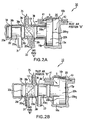
- FIGS 2A and 2B illustrate one embodiment of the gas delivery valve 10.
- the gas delivery valve 10 has a body 10b with passages that define at least one gas flow path (the gas flow path or paths referred to generally as feature 10f) and a receptacle 10r for a spool 20. Although shown as one spool and two different gas inlet ports (for Gas A and Gas B, respectively), multiple spools can be used in series and/or parallel to achieve different gas flow path options.
- the valve body and spool may be configured for an "on-off' operation of a single gas to deliver or hold back a single gas (typically hyperpolarized gas) and/or to open and close the single gas flow path (not shown) for controlled inhalation delivery to a subject.
- the gas delivery valve 10 can also be configured to select between inhale, exhale, and/or breath-hold ventilation operations.
- the spool 20 includes a head 20h and a stem segment 20s.
- the valve body receptacle 10r includes pilot gas ports 41, 43 each positioned on opposing sides of the spool head portion 10c of the receptacle 10r so as to be facing opposing sides of the spool head 20h 1 , 20h 2 , respectively.
- pilot air will be used instead of "pilot gas” in the description that follows.
- other gases may be used to actuate the spool(s) as desired.
- other fluids, including liquids may also be used to actuate the spools in certain applications, although gas signals will typically provide faster transmissions.
- pilot air is directed to enter either port 43 or 41 and apply pressure to the respective face of the spool head 20h.
- Increasing and decreasing the pilot air pressure will adjust the speed (faster and slower, respectively).
- the pressure from the pilot air against the spool head 20h forces the spool 20 to translate away from the pilot air input port.
- the translation positions the spool stem 20s in different operative and/or inoperative locations in the valve body 10b.
- the spool 20 translates (back and forth) to open and close selected gas flow paths in response to pilot gas transmitted into the valve body cavity of the spool head.
- the receptacle 10r for the spool head 20h is sized and configured so that the head of the spool 20h can translate a desired stroke distance "S" to open and close one or more gas flow paths.
- Figure 2A illustrates the pilot air being directed into port 43 on the outer face of the spool head 20h 2 to force the spool 20 to travel its stroke length "S" to position the inner face of the spool head 20h 1 against the receptacle perimeter 10p.
- the stroke translation positions different portions of the stem 20s in fluid communication with the gas exit port 35.
- the stem 20s includes two gas path segments, 20s 1 and 20s 2 , each sandwiched by seals 38.
- the seals 38 are sized and configured to reside in recesses 38r formed into the valve body at different locations along the spool travel path.
- the seals 38 may be O-rings or other suitable sealant members, formed of a material that inhibits depolarization that can enclose opposing portions of the stem segments 20s 1 , 20s 2 during engagement of the selected gas flow path.
- Other sealing arrangements can also be used, such as by configuring the valve body and the stem to sealably matably engage at desired positions as will be understood by one of skill in the art.
- the spool 20 is in a position in which segment 20s 1 is located so that gas path entry port 33 is in fluid communication with exit port 35 to open gas path "A" to deliver gas A through the gas delivery valve 10.
- Either Gas path A or B is typically for supplying hyperpolarized gas (such as a hyperpolarized noble gas including, but not limited to, hyperpolarized 129 Xe or 3 He).
- Figure 2B illustrates pilot air being directed into port 41 with the outer face of the spool head 20h 2 being translated to reside against the perimeter 10p of the valve body receptacle 10r. This movement positions stem segment 20s 2 proximate exit port 35 to allow port 31 to be in fluid communication with the gas exit port 35 across the spool stem 20s to open gas path B and close gas path A.
- valve body gas ports can be used (one or three, four or more).
- the stem 20s can be reconfigured to concurrently release gas A and gas B (combined), or to deliver other gases.
- additional valve ports can be added to allow porting in series or parallel.
- the spool head 20h may be configured to have other stroke patterns such that the spool head 20h surfaces are not required to stop against the perimeter 10p of the valve body receptacle to actuate desired gas flow paths 10f as will be understood by those of skill in the art.
- the spools are double acting spools that allow a single pulse of pilot air to actuate the valve to cause the spool 20 to move to the desired position and open or close the selected gas flow path.
- the pilot pressure can be released to atmosphere in between alternating pulses of pilot air to "toggle” the spool 20 from “inhale” to "exhale.”
- the spool actuation (back and forth) either opens and/or closes one or more gas paths. The actuation can occur during the steep rinsing edge of the pilot pressure curve as shown, for example, in Figure 8 .
- the rising edge operation is in contrast to conventional diaphragm 66 valve configurations (see, e.g., Figures 6A-6C ) that typically actuate the diaphragm to move to its operative position late in the falling edge portion of the response curve.
- An exemplary diaphragm pressure response curve is shown in Figure 7 .
- the spool configuration pressure at which the spool actuates and the gas path opens and/or closes occurs earlier in the pressure response cycle than with the diaphragm valve.
- Figure 8 illustrates that the length or pulse duration of the pilot signal is typically less than about 30ms, with the spool actuation delay being about 40ms or less.
- the response delay can be the same for either inhale or exhale pilot signals.
- the inhale and exhale pilot pressure can be substantially the same.
- the spool actuation response is relatively quick (less than about 50ms, and typically less than about 40ms) and acts with less than half the delay associated with conventional diaphragm valve configurations as shown in Figure 7 .
- the spool can be actuated with a response pressure that is between about 200-400 Pa [30-60 psi].
- the volume of the pilot air circuit can be sized for quick response by optimizing the volume, port diameters and the like to provide a reduced spool stroke cycle.
- the spool stroke can be about 4mm [0.125 inches]
- the pilot circuit volume can be about 62 ml per cm [0.00306 in 3 per inch] of tubing.
- the pilot circuit volume may be about 9 ml [0.5508 in 3 ].
- the pilot port diameters may be about 1,5 mm [0.0625 inches].
- the spool head size may be about 15 mm [0.625 inches] (diameter).
- the spool head is sized to have an area of between about 0,3-3 cm 2 [0.05-0.45 in 2 ].
- the spool can be configured to weigh less than about 1 gram.
- the spool is operably associated with two pilot valves "V" (one in fluid communication with pilot-port 41 and the other in fluid communication with pilot port 43 ).
- the two pilot valves can be electric, three-way, normally closed solenoid valves.
- the normally closed pilot valve sending the command pilot pulse can be vented to atmosphere so that the command pilot pressure does not offer resistance to the opposing pilot air when it is actuated to drive the spool back to its former position.
- the dual acting spool configuration can be operated so that the pilot pressure is always on to provide a biasing mechanism to cause the spool 20 to return to a neutral or normal operating position after the pilot pulse signal is transmitted.
- the air is always directed to one side of the other to bias the location of the spool without requiring the use of a spring member.
- a polarization friendly spring formed of a resilient non-ferromagnetic metal or elastomeric material
- the valve body and its internal components can be formed from and/or coated with a material or materials selected for the ability to inhibit depolarization of hyperpolarized gas (such as due to relaxation attributed to gas interaction therewith). Coatings such as sol-gel coatings, deuterated polymer coatings, metal film coatings and other coatings and non-magnetic materials that inhibit depolarization have also been proposed. See, e.g., U.S. Patent Application No. 09/485,476 and U.S. Patent Nos. 5,612,103 and 6,423,387 .
- valve body and/or components may be formed of materials such as, but not limited to, aluminum, TEDLAR, TEFLON, PTFE, DELRIN (acetal), and the like. Care should be taken to reduce the sources of friction by providing a smooth surface finish, and reducing the number of O-rings or selecting the O-ring material to reduce friction.
- the valve body can be fabricated to tolerances to provide sufficient seals and yet provide reduced friction between the spool and valve body receptacle.
- the valve body bore finishes, O-ring compression, and lubricants may all be considered to reduce the sources of friction.
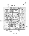
- FIG. 3 illustrates a valve 10 having a valve body 10b that defines three spool receptacles 10r each for accommodating one of spools 20A, 20B, 20C, respectively.
- Control of the input of Gas A into the valve 10 is controlled by a first spool 20A that is positioned to control the gas port 133 that is in fluid communication with the external Gas A source.
- Valve body 10b defines a gas flowpath 135 extending in fluid communication between the spool receptacles for spools 20A and 20C while extending about the spool receptacle for spool 20B.
- Spool 20A has two operative positions, A1 and A2.
- Valve body 10b defines exit port 235 for conducting gas to a subject for inhaling and from a subject on exhaling. Suitable gas conduits, not shown, are contemplated to carry the gases to and from the appropriate ports of valve 10.
- valve body 10b defines a second elongate flowpath 35 extending in fluid communication between the spool receptacle for spool 20B and an aperture 37 opening into the spool receptacle for spool 20C.
- Aperture 37 desirably is located opposite the open end of flowpath 135 from the spool receptacle for spool 20A, although they may be arranged differently, or even co-extensively.
- the positioning of the spool segments 20s 1 , 20s 2 of spools 20A and 20B can be adjusted to allow Gas B to be output alone or combined with Gas A, as will be further described for Figures 4A-4H hereinbelow.
- the second spool 20B is shown in position B2 with the Gas B input port 31 isolated from flowpath 35 and Gas A allowed to pass all the way through to exit port 235.
- Gas B will be able to travel through flowpath 35 and out exit port 235.
- the third spool 20C is configured to control the inhale and exhale configuration of the valve 10.
- the third spool 20C has an IN position and an EX position.
- the valve body 10b defines an exit ports 235 and 236 in fluid communication with the spool receptacle 10r for spool 20C.
- the position of the third spool 20C cooperates with the associated valve receptacle 10r to either direct flow from about spool segment 20s 2 and out exit port 235 when spool 20C is in the IN (or inhale) position, or from exit port 235, about spool segment 20s 1 and out exit port 236 when spool 20C is in the EX (or exhale) position, as desired.
- the gas flow path depicted in Figure 3 is illustrated by the dark shading extending from Gas A input port 133 to the valve 10 exit inhale port 135 that is actuated to expel Gas A (alone) through the ventilation inhale port 135.
- valve body 10b further defines pilot air ports (not shown) for directing air against either side of the spool heads for spools 20A, 20B, and 20C which are also located outside the plane of the view.
- pilot air ports would be configured to incorporate the features of ports 41 and 43 described in Figures 2A and 2B .
- a pair of opposing pilot air ports desirably provide pilot air to the opposing faces of each spool head 20h. The valving for such ports are desirably located outside of valve body 10b, although such valves may be incorporated into valve body 10b as well.
- each spool may be acted upon by a single pilot air port which directs air against one face of each spool head 20h to move the spool in a first direction to its first position and draws air out of bore 10C for each spool to force the spool to travel the opposite direction to its second position.
- opposing pilot air ports may act in unison to actively force air into, or out of, bore 10C in order to urge the spool to the desired position.
- Figure 5 depicts the three spools 20 of Figure 3 specifically and of the present invention generally.
- Figure 5 further illustrate spool segments 20s 1 , 20s 2 of each spool 20, as well as spool head 20h and the gaskets 38 which sealingly engage the valve body 10b for directing flow therethrough.
- Figures 4A-4H illustrate examples of different valve positions of a three-spool configuration that can be used to provide selection of ventilation breath outputs and/or inputs according to embodiments of the present invention.
- Gas A will be described as a hyperpolarized gas and Gas B as a non-polarized gas.
- a reverse configuration can be used.
- breath-hold means that the gas or gases are held in the lungs for a breath-hold time to facilitate bio-uptake of the gas an/or allow a stronger hyperpolarized gas signal other normal respiration.
- the breath-hold duration may be between 5-30 seconds.
- valve 10 can be actuated to accommodate or provide (a) Gas “A” inhale; (b) Gas “B” inhale; (c) Gas “A” + Gas “B” inhale; (d) exhale; (e) partial exhale and breath hold; (f) Gas “A” inhale and breath hold; (g) Gas “B” inhale and hold; and (h) Gas “A” + Gas “B” inhale and breath hold.
- the valve spool configuration can be adjusted to provide all or selected ones of these ventilation breath inputs/outputs and may use lesser or greater numbers of spools and/or respective spool segments as well as different porting configurations to provide the desired breath outputs/inputs.
- Figure 4A illustrates the operative position of the three spools to provide Gas “A” + Gas “B” inhale.
- Figure 4B illustrates Gas “A” output in an inhale breath-hold position.
- Figure 4C shows the positions of the spools for Gas “A” inhale.
- Figure 4D shows the spool positions for exhale;
- Figure 4E shows the spools in position for Gas “B” inhale and hold.
- Figure 4F shows the positions of the spools for Gas “A” blocked and
- Figure 4G shows an exhale hold configuration.
- Figure 4H illustrates a Gas "A"+ Gas “B” hold configuration.
- the valve spool positions and sequencing of operation can be automated and controlled by a computer control program.
- the actuation or piloting of the valve spools 20A, 20B, 20C can be driven through the computer control program by six (6) electric three-way normally closed solenoid valves.
- suitable solenoid valves include, Clippard EC-#M-12V, Cincinnati, OH, and MAC 42A-AMP-000-GDDB-1BE, Wixom, MI.
- a command is given to actuate an individual spool to a desired position.
- the command triggers the transmission of a 20-30ms pilot command pulse signal to the individual spool.
- the single command pulse toggles the spool to the desired position.
- the normally closed solenoid valve vents to atmosphere so that the pilot pressure for that spool does not generate undue resistance to the opposing pilot gas (air) when it is actuated to drive the spool back to its previous position.
- the hyperpolarized gas may be a hyperpolarized noble gas such as 3 He and/or 129 Xe.
- the non-polarized gas may be a mixture of non-polarized gases.
- the non-polarized gas can be selected to inhibit depolarization of the hyperpolarized gas, and may be also selected for biocompatibility. Examples of suitable non-polarized gases include, but are not limited to, nitrogen, xenon, and helium.
- the valve body 10b ( Figure 4 ) can be configured to hold a plurality of individually operable spools in close proximity.
- the valve spools or translating components may be configured so that the centerlines of adjacent receptacles are less 10 components may be configured so that the centerlines of adjacent receptacles are less than 25 mm [1inch] apart, and, in certain embodiments, are about 12 mm [0.5 inches] apart.
- the valve can be configured to reduce the number of breath cycles that are required for switching between gases output to a subject.
- the spool configuration is such that dead volume for the inhaled gas(es) can be reduced. Dead volume is the volume within the valve that needs to be filled with gas before the gas will reach the subject.
- the dead volume for the gas delivery valve can be about 0.445 ml. In particular embodiments, the dead volume may be even less, such as on the order of about 0.223 ml.
Landscapes
- Physics & Mathematics (AREA)
- Engineering & Computer Science (AREA)
- General Engineering & Computer Science (AREA)
- Health & Medical Sciences (AREA)
- Condensed Matter Physics & Semiconductors (AREA)
- Nuclear Medicine, Radiotherapy & Molecular Imaging (AREA)
- Mechanical Engineering (AREA)
- General Physics & Mathematics (AREA)
- Life Sciences & Earth Sciences (AREA)
- High Energy & Nuclear Physics (AREA)
- Radiology & Medical Imaging (AREA)
- General Health & Medical Sciences (AREA)
- Signal Processing (AREA)
- Medical Informatics (AREA)
- Pathology (AREA)
- Biomedical Technology (AREA)
- Heart & Thoracic Surgery (AREA)
- Biophysics (AREA)
- Molecular Biology (AREA)
- Surgery (AREA)
- Animal Behavior & Ethology (AREA)
- Public Health (AREA)
- Veterinary Medicine (AREA)
- Magnetic Resonance Imaging Apparatus (AREA)
- Medicines Containing Antibodies Or Antigens For Use As Internal Diagnostic Agents (AREA)
Claims (16)
- Gaszuführungsventil [10] für einen Ventilator, gestaltet, um einem Subjekt hyperpolarisiertes Gas zuzuführen, wobei das Gaszuführungsventil [10] umfasst:einen Ventilkörper [10b] mit mindestens einem Gasströmungsweg [10f], der sich zwischen mindestens einem Gaseinlassanschluss [31, 33] undmindestens einem Gasauslassanschluss [35] erstreckt, und mit mindestens einem Schieberaufnahmeteil [10r], wobei einer des mindestens einen Gaseinlassanschlusses [31, 33] in fluider kommunikativer Verbindung mit einer Quelle hyperpolarisierten Gases ist;mindestens ein Schieberelement [20], das in einem jeweiligen des mindestens einen Schieberaufnahmeteils [10r] des Ventilkörpers [10b] angeordnet ist,wobei das Schieberelement [20] so gestaltet und bemessen ist, dass es mit dem Ventilkörper [10b] zusammenwirkt, um den mindestens einen Gasströmungsweg [10f] selektiv zu öffnen und zu schließen; und
mindestens einen Pilotfluidanschluss in fluider kommunikativer Verbindung mit dem Schieberaufnahmeteil [10r],
wobei, bei Betrieb, ein Pilotfluidbefehlsimpulssignal mit zugehörigem Druck und zugehöriger Dauer, in den Pilotfluidanschluss übertragen wird, um dadurch den Schieber [20] zu zwingen, eine Betätigungsstrecke in einer vorbestimmten Richtung im Ventilkörperaufnahmeteil [10r] geradlinig zurückzulegen, um den mindestens einen Gasströmungsweg [10f] zu öffnen und/oder zu schließen. - Gaszuführungsventil [10] nach Anspruch 1, wobei der Ventilkörper [10b] eine Mehrzahl verschiedener Gasströmungswege [10f], die steuerbar auswählbar sind, in demselben aufweist, wobei jeder einen zugehörigen Gaseinlassanschluss [31, 33] aufweist, einer der Gaseinlassanschlüsse [31, 33] in fluider kommunikativer Verbindung mit der Quelle hyperpolarisierten Gases ist und ein anderer der Gaseinlassanschlüsse [31, 33] in fluider kommunikativer Verbindung mit einer Quelle nicht polarisierten Gases ist, wobei das Schieberelement [20] eine Mehrzahl voneinander beabstandeter Schaftsegmente [20s] mit einem zwischen denselben angeordneten Dichtungselement [38] umfasst, und wobei die Position des Schiebers [20] im Ventilkörper [10b] ein jeweiliges der Schaftsegmente [20s] an einem jeweiligen der Gaseinlassanschlüsse [31, 33] und dem Gasauslassanschluss [35] ausrichtet, um einen jeweiligen Gasströmungsweg [10f] zu öffnen, um das hyperpolarisierte Gas oder das nicht polarisierte Gas, das aus dem ausgerichteten Gaseinlassanschluss [31, 33] zum Gasauslassanschluss [35] geliefert wird, einem Subjekt zuzuführen.
- Gaszuführungsventil [10] nach Anspruch 1, wobei der Schieber [20] einen Schieberkopf [20h] und einen länglichen Schaft [20s] umfasst.
- Gaszuführungsventil [10] nach Anspruch 3, wobei das Schieberaufnahmeteil [10r] im Ventilkörper [10b] einen Schieberkopfabschnitt [10c] beinhaltet, der eine axiale Länge aufweist, die größer ist als der Schieberkopf [20h], und wobei die Länge des Aufnahmeteilschieberkopfabschnitts [10c] die Hubbetätigungstranslationsstrecke [S] des Schiebers [20] festlegt.
- Gaszuführungsventil [10] nach Anspruch 4, wobei der mindestens eine Pilotfluidanschluss in zwei Fluidpilotanschlüssen [41, 43] besteht, die je auf gegenüberliegenden Seiten des Schieberaufnahmeteilabschnitts [10c] positioniert sind, um nächst einer jeweiligen der Hauptoberflächen [20h1, 20h2] des Schieberkopfs [20h] während des Betriebs zu sein.
- Gaszuführungsventil [10] nach Anspruch 5, wobei die Pilotfluidanschlüsse [41, 43] Pilotgasanschlüsse sind, wobei das Ventil weiterhin eine Pilotgasquelle umfasst, die gestaltet ist, um ein Pilotbefehlsimpulssignal mit einer Dauer zu liefern, die kürzer ist als etwa 40 ms.
- Gaszuführungsventil [10] nach Anspruch 6, wobei das Pilotbefehlsimpulssignal ein Schieberdruckreaktionsprofil erzeugt, das eine vom Beginn des Pilotbefehlsimpulssignals zu den Maxima des Druckreaktionsprofils gemessene Verzögerung aufweist, die kürzer ist als etwa 50 ms.
- Gaszuführungsventil [10] nach Anspruch 7, wobei das Schieberdruckreaktionsprofil einen steigenden Anfangsabschnitt aufweist, der auf zwischen etwa 200 - 400 Pa ansteigt.
- Gaszuführungsventil [10] nach Anspruch 8, wobei, bei Betrieb, der Schieber [20] die Hubbetätigungsstrecke [S] im Ventilkörper [10b] in Reaktion auf den steigenden Anfangsabschnitt des Schieberdruckreaktionsprofils zurücklegt.
- Gaszuführungsventil [10] nach Anspruch 1, wobei mindestens ein Gasströmungsweg [10f] des Ventilkörpers [10b] in einer Mehrzahl verschiedener Gasströmungswege [10f] besteht, wobei der Ventilkörper [10b] eine Mehrzahl voneinander beabstandeter Schieberaufnahmeteile [10r] und eine entsprechende Anzahl von Schiebern [20] umfasst, wobei jedes Schieberaufnahmeteil [10r] zwei Pilotanschlüsse in fluider kommunikativer Verbindung mit einer Pilotgasquelle umfasst, und wobei jeweilige Schieber [20] gestaltet sind, um Gasströmungswege [10f] im Ventilkörper [10b] in Reaktion auf dahin übertragene Pilotbefehlsimpulssignale selektiv zu öffnen und zu schließen, um eine Mehrzahl verschiedener Gase aus dem Gaszuführungsventil [10] regelbar seriell oder gleichzeitig herauszulassen.
- Gaszuführungsventil [10] nach Anspruch 10, wobei der Ventilkörper einen Ausatmungs-Anschluss nächst dem Auslassanschluss [35] umfasst, wobei die Mehrzahl von Aufnahmeteilen [10r] und Schiebern [20] ein erstes Aufnahmeteil [10r] und einen entsprechenden ersten Schieber [20A] beinhaltet, angeordnet nächst dem Ausatmungs-Anschluss und dem Auslassanschluss [35], ein zweites Aufnahmeteil [10r] und einen zweiten Schieber [20B], beabstandet von und in fluider kommunikativer Verbindung mit dem ersten Schieber [20A], wobei das zweite Aufnahmeteil [10r] einen Gaseinlassanschluss B [31] aufweist, um nicht polarisiertes Gas B während des Betriebs zuzuführen, und ein drittes Aufnahmeteil [10r] und einen dritten Schieber [20C], beabstandet vom ersten [20A] und zweiten [20B] Schieber und in fluider kommunikativer Verbindung mit dem zweiten Schieber [20B], wobei das dritte Aufnahmeteil [10r] einen Gaseinlassanschluss A [33] aufweist, um hyperpolarisiertes Gas A während des Betriebs zuzuführen, und wobei der Gasseinlassanschluss zum ersten Aufnahmeteil [10r] in entweder einem oder beiden der Auslassanschlüsse [35, 235] aus dem zweiten und dritten Aufnahmeteil [10r] besteht.
- Gaszuführungsventil [10] nach Anspruch 10, wobei die Gasströmungswege [10f] einen ersten Einatmungs-Gasströmungsweg, einen zweiten Ausatmungs-Gasströmungsweg und einen dritten Atemanhaltungs-Gasströmungsweg umfassen, von denen jeder ein aus der Ferne wählbarer Gasströmungsweg ist.
- Gaszuführungsventil [10] nach Anspruch 10, wobei die Schieber [20] und der Ventilkörper [10b] angeordnet sind, um zu ermöglichen, dass hyperpolarisiertes Gas, nicht polarisiertes Gas, oder eine Kombination aus dem hyperpolarisierten Gas und dem nicht polarisierten Gas, aus dem Einatmungs- und/oder Atemanhaltungs-Gasströmungsweg [10f] herausgelassen werden.
- Gaszuführungsventil [10] nach Anspruch 6, wobei sich der Schieber [20] zwischen einer ersten und zweiten Betriebsposition [A1, A2] hin- und herbewegt, wobei das Ventil weiterhin zwei normal geschlossene Magnetventile [V] umfasst, von denen eines operativ zu jedem der Pilotfluidanschlüsse [41, 43] und der Pilotgasquelle gehört, wobei die Magnetventile gestaltet sind, um die Betätigung des Schiebers [20] zwischen der ersten und zweiten Position zu steuern, wobei, bei Betrieb, nachdem ein Befehlspilotimpulssignal zu einem Schieberkopf über einen ausgewählten der Pilotanschlüsse [41, 43] übertragen worden ist, um den Schieber [20] zu zwingen, sich geradlinig aus der ersten Position [A1] zur zweiten Position [A2] zu bewegen, das jeweilige normal geschlossene Pilotventil [V], das zu dem ausgewählten Pilotanschluss gehört, zur Atmosphäre entlüftet, so dass Pilotdruck im Schieberkopfaufnahmeteilabschnitt [10c] verringert wird, um eine Interferenz mit dem entgegengesetzten Pilotgassignal vom anderen Pilotanschluss zu verhindern, wenn der Ventilschieber betätigt wird, um den Schieber [20] zurück zu seiner ersten Position [A1] zu treiben.
- Gaszuführungsventil [10] nach Anspruch 14, weiterhin umfassend ein Computermodul mit Computerprogrammcode, der aus der Ferne die Sequenz von Pilotbefehlssignalen zu jeweiligen Schiebern [20] steuert, um die Schieber [20] zu betätigen und gewünschte Gasströmungswege [10f] im Ventilkörper [10b] automatisch zu öffnen und zu schließen, so dass mit der gewünschten Sequenz von hyperpolarisiertem Gas und nicht polarisiertem Gas zu ventiliert wird.
- Gaszuführungsventil [10] nach Anspruch 11, weiterhin umfassend eine Mehrzahl von Leitungen, die sich vom Ventilkörper [10b] auswärts erstrecken, um eine Mehrzahl von Gasströmungswegen [10f] festzulegen, wobei die Mehrzahl von Leitungen zwei Pilotgasströmungswegleitungen für jeden Schieberkopfaufnahmeteilabschnitt [10c] im Ventilkörper [10b], mindest eine Leitung für hyperpolarisiertes Gas, die sich von der Quelle hyperpolarisierten Gases zu einem entsprechenden Gaseinlassanschluss [33] im Ventilkörper [10b] erstreckt, und mindestens eine Leitung für nicht polarisiertes Gas beinhaltet, die sich von einer Quelle nicht polarisieren Gases zu einem entsprechenden Gaseinlassanschluss [31] im Ventilkörper [10b] erstreckt.
Applications Claiming Priority (3)
| Application Number | Priority Date | Filing Date | Title |
|---|---|---|---|
| US45020903P | 2003-02-26 | 2003-02-26 | |
| US450209P | 2003-02-26 | ||
| PCT/US2004/005567 WO2004077085A2 (en) | 2003-02-26 | 2004-02-25 | Mri/nmr compatible hyperpolarized gas delivery valves for ventilators and associated gas delivery methods |
Publications (2)
| Publication Number | Publication Date |
|---|---|
| EP1599740A2 EP1599740A2 (de) | 2005-11-30 |
| EP1599740B1 true EP1599740B1 (de) | 2009-02-18 |
Family
ID=32927621
Family Applications (1)
| Application Number | Title | Priority Date | Filing Date |
|---|---|---|---|
| EP04714611A Expired - Lifetime EP1599740B1 (de) | 2003-02-26 | 2004-02-25 | Für mri/nmr geeignetes ventil für die gaszuführung eines ventilators und damit verbundene verfahren der gaszuführung |
Country Status (12)
| Country | Link |
|---|---|
| US (1) | US20070144523A1 (de) |
| EP (1) | EP1599740B1 (de) |
| JP (1) | JP2006519064A (de) |
| KR (1) | KR20050103238A (de) |
| CN (1) | CN1754103A (de) |
| AT (1) | ATE423326T1 (de) |
| AU (1) | AU2004214924A1 (de) |
| CA (1) | CA2515467A1 (de) |
| DE (1) | DE602004019497D1 (de) |
| DK (1) | DK1599740T3 (de) |
| ES (1) | ES2321101T3 (de) |
| WO (1) | WO2004077085A2 (de) |
Families Citing this family (49)
| Publication number | Priority date | Publication date | Assignee | Title |
|---|---|---|---|---|
| US20100170505A1 (en) * | 2002-11-15 | 2010-07-08 | Speight Bryan Barker | Device for enhancing well-being |
| FR2858236B1 (fr) | 2003-07-29 | 2006-04-28 | Airox | Dispositif et procede de fourniture de gaz respiratoire en pression ou en volume |
| US20080242974A1 (en) * | 2007-04-02 | 2008-10-02 | Urbahn John A | Method and apparatus to hyperpolarize materials for enhanced mr techniques |
| DE102007039664B4 (de) * | 2007-08-22 | 2015-01-22 | Robert Bosch Gmbh | Pneumatisches Wegeventil mit einem reibungsarmen Ventilschieber |
| US8457706B2 (en) | 2008-05-16 | 2013-06-04 | Covidien Lp | Estimation of a physiological parameter using a neural network |
| CN102056538B (zh) | 2008-06-06 | 2014-10-15 | 柯惠有限合伙公司 | 用于在换气系统中确定患者努力及/或呼吸参数的系统及方法 |
| US8393323B2 (en) | 2008-09-30 | 2013-03-12 | Covidien Lp | Supplemental gas safety system for a breathing assistance system |
| US8302602B2 (en) | 2008-09-30 | 2012-11-06 | Nellcor Puritan Bennett Llc | Breathing assistance system with multiple pressure sensors |
| US8434479B2 (en) | 2009-02-27 | 2013-05-07 | Covidien Lp | Flow rate compensation for transient thermal response of hot-wire anemometers |
| JP5818214B2 (ja) * | 2009-11-11 | 2015-11-18 | ザ ボード オブ トラスティーズ オブ ザ レランド スタンフォード ジュニア ユニバーシティー | 人工呼吸器 |
| US8469031B2 (en) | 2009-12-01 | 2013-06-25 | Covidien Lp | Exhalation valve assembly with integrated filter |
| US8439036B2 (en) | 2009-12-01 | 2013-05-14 | Covidien Lp | Exhalation valve assembly with integral flow sensor |
| US8439037B2 (en) | 2009-12-01 | 2013-05-14 | Covidien Lp | Exhalation valve assembly with integrated filter and flow sensor |
| US8469030B2 (en) | 2009-12-01 | 2013-06-25 | Covidien Lp | Exhalation valve assembly with selectable contagious/non-contagious latch |
| US8434481B2 (en) | 2009-12-03 | 2013-05-07 | Covidien Lp | Ventilator respiratory gas accumulator with dip tube |
| USD655809S1 (en) | 2010-04-27 | 2012-03-13 | Nellcor Puritan Bennett Llc | Valve body with integral flow meter for an exhalation module |
| USD655405S1 (en) | 2010-04-27 | 2012-03-06 | Nellcor Puritan Bennett Llc | Filter and valve body for an exhalation module |
| USD653749S1 (en) | 2010-04-27 | 2012-02-07 | Nellcor Puritan Bennett Llc | Exhalation module filter body |
| US8714154B2 (en) | 2011-03-30 | 2014-05-06 | Covidien Lp | Systems and methods for automatic adjustment of ventilator settings |
| US9452409B2 (en) | 2011-04-22 | 2016-09-27 | Vanderbilt University | Para-hydrogen polarizer |
| US9629971B2 (en) | 2011-04-29 | 2017-04-25 | Covidien Lp | Methods and systems for exhalation control and trajectory optimization |
| US9364624B2 (en) | 2011-12-07 | 2016-06-14 | Covidien Lp | Methods and systems for adaptive base flow |
| US9498589B2 (en) | 2011-12-31 | 2016-11-22 | Covidien Lp | Methods and systems for adaptive base flow and leak compensation |
| US9144658B2 (en) | 2012-04-30 | 2015-09-29 | Covidien Lp | Minimizing imposed expiratory resistance of mechanical ventilator by optimizing exhalation valve control |
| US10362967B2 (en) | 2012-07-09 | 2019-07-30 | Covidien Lp | Systems and methods for missed breath detection and indication |
| USD731049S1 (en) | 2013-03-05 | 2015-06-02 | Covidien Lp | EVQ housing of an exhalation module |
| US10213575B2 (en) * | 2013-03-07 | 2019-02-26 | Koninklijke Philips N.V. | Valve |
| USD731065S1 (en) | 2013-03-08 | 2015-06-02 | Covidien Lp | EVQ pressure sensor filter of an exhalation module |
| USD736905S1 (en) | 2013-03-08 | 2015-08-18 | Covidien Lp | Exhalation module EVQ housing |
| USD701601S1 (en) | 2013-03-08 | 2014-03-25 | Covidien Lp | Condensate vial of an exhalation module |
| USD731048S1 (en) | 2013-03-08 | 2015-06-02 | Covidien Lp | EVQ diaphragm of an exhalation module |
| USD692556S1 (en) | 2013-03-08 | 2013-10-29 | Covidien Lp | Expiratory filter body of an exhalation module |
| USD693001S1 (en) | 2013-03-08 | 2013-11-05 | Covidien Lp | Neonate expiratory filter assembly of an exhalation module |
| USD744095S1 (en) | 2013-03-08 | 2015-11-24 | Covidien Lp | Exhalation module EVQ internal flow sensor |
| US9950135B2 (en) | 2013-03-15 | 2018-04-24 | Covidien Lp | Maintaining an exhalation valve sensor assembly |
| US11717247B2 (en) * | 2013-10-18 | 2023-08-08 | Andreas GUTZEIT | Blood flow control system and methods for in-vivo imaging and other applications |
| US9808591B2 (en) | 2014-08-15 | 2017-11-07 | Covidien Lp | Methods and systems for breath delivery synchronization |
| US10738746B1 (en) * | 2014-09-02 | 2020-08-11 | Alafei Foods Limited | Dual piston valve for flow control of two distinct liquid fuels |
| US20160061337A1 (en) * | 2014-09-02 | 2016-03-03 | Plant Oil Powered Diesel Fuel Systems, Inc. | Dual Piston Valve for Flow Control of Two Distinct Liquid Fuels |
| US9950129B2 (en) | 2014-10-27 | 2018-04-24 | Covidien Lp | Ventilation triggering using change-point detection |
| US10337638B2 (en) * | 2014-12-01 | 2019-07-02 | National Oilwell Varco, L.P. | Slow-shift SPM valve |
| USD775345S1 (en) | 2015-04-10 | 2016-12-27 | Covidien Lp | Ventilator console |
| EP3793656A1 (de) | 2018-05-14 | 2021-03-24 | Covidien LP | Systeme und verfahren zur erfassung der atemleistung unter verwendung von signalverzerrung |
| US11752287B2 (en) | 2018-10-03 | 2023-09-12 | Covidien Lp | Systems and methods for automatic cycling or cycling detection |
| CN110081956B (zh) * | 2019-04-29 | 2024-05-10 | 航空工业(新乡)计测科技有限公司 | 可变粘度滑油微小流量标准装置 |
| WO2021188909A1 (en) * | 2020-03-19 | 2021-09-23 | The Regents Of The University Of California | Mechanical ventilator with a fixed number of orifice plates to generate constant flow paths |
| US11896767B2 (en) | 2020-03-20 | 2024-02-13 | Covidien Lp | Model-driven system integration in medical ventilators |
| US11872349B2 (en) | 2020-04-10 | 2024-01-16 | Covidien Lp | Systems and methods for increasing ventilator oxygen concentration |
| WO2021207600A1 (en) | 2020-04-10 | 2021-10-14 | Covidien Lp | Gas mixing system for medical ventilator |
Family Cites Families (8)
| Publication number | Priority date | Publication date | Assignee | Title |
|---|---|---|---|---|
| US3575211A (en) * | 1969-06-23 | 1971-04-20 | Robertshaw Controls Co | Pneumatic control system and relay valve construction therefor or the like |
| JPS5011553Y1 (de) * | 1973-03-16 | 1975-04-10 | ||
| FR2297642A1 (fr) * | 1975-01-17 | 1976-08-13 | France Etat | Appareil respiratoire de plongee autonome |
| IL85605A (en) * | 1987-03-31 | 1993-08-18 | Rosenberg Peretz | Automatic shut-off valve |
| JPH0519760U (ja) * | 1991-08-28 | 1993-03-12 | エヌオーケー株式会社 | スプールバルブ |
| JP2001522681A (ja) * | 1997-11-14 | 2001-11-20 | ヴァイラー、ノーバート | 流体投与装置 |
| NZ508719A (en) * | 1998-06-17 | 2002-10-25 | Medi Physics Inc | Hyperpolarized gas transport device with at least one gas chamber and a electromagnet providing a magnetic holding field |
| DE10000675C2 (de) * | 2000-01-11 | 2001-11-15 | Otten Ernst Wilhelm | Lineardurchführung, Vorrichtung und Verfahren zur hochproduktiven Erzeugung von hoch kernspinpolarisiertem Helium-3 Gas |
-
2004
- 2004-02-25 EP EP04714611A patent/EP1599740B1/de not_active Expired - Lifetime
- 2004-02-25 CA CA002515467A patent/CA2515467A1/en not_active Abandoned
- 2004-02-25 US US10/547,436 patent/US20070144523A1/en not_active Abandoned
- 2004-02-25 DK DK04714611T patent/DK1599740T3/da active
- 2004-02-25 KR KR1020057015753A patent/KR20050103238A/ko not_active Withdrawn
- 2004-02-25 ES ES04714611T patent/ES2321101T3/es not_active Expired - Lifetime
- 2004-02-25 AU AU2004214924A patent/AU2004214924A1/en not_active Abandoned
- 2004-02-25 CN CNA2004800051690A patent/CN1754103A/zh active Pending
- 2004-02-25 AT AT04714611T patent/ATE423326T1/de not_active IP Right Cessation
- 2004-02-25 JP JP2006503861A patent/JP2006519064A/ja active Pending
- 2004-02-25 DE DE602004019497T patent/DE602004019497D1/de not_active Expired - Lifetime
- 2004-02-25 WO PCT/US2004/005567 patent/WO2004077085A2/en not_active Ceased
Also Published As
| Publication number | Publication date |
|---|---|
| EP1599740A2 (de) | 2005-11-30 |
| US20070144523A1 (en) | 2007-06-28 |
| DK1599740T3 (da) | 2009-06-08 |
| ES2321101T3 (es) | 2009-06-02 |
| DE602004019497D1 (de) | 2009-04-02 |
| WO2004077085A2 (en) | 2004-09-10 |
| CA2515467A1 (en) | 2004-09-10 |
| ATE423326T1 (de) | 2009-03-15 |
| KR20050103238A (ko) | 2005-10-27 |
| WO2004077085A3 (en) | 2004-11-04 |
| AU2004214924A1 (en) | 2004-09-10 |
| CN1754103A (zh) | 2006-03-29 |
| JP2006519064A (ja) | 2006-08-24 |
Similar Documents
| Publication | Publication Date | Title |
|---|---|---|
| US20070144523A1 (en) | Mri/nmr compatible hyperpolarized gas delivery valves for ventilators and associated gas delivery methods | |
| Hedlund et al. | MR-compatible ventilator for small animals: computer-controlled ventilation for proton and noble gas imaging | |
| EP0969894B1 (de) | Druckpuls-ventil mit variabler öffnung | |
| US7370651B2 (en) | Gas conserving device | |
| DE69526549T2 (de) | Gerät zum Steuern eines Ausatmungskreislaufs eines Beatmungsgeräts | |
| EP0800412A4 (de) | Tragbarer,mechanischer und mit einem schleppkompressor angetriebenes beatmungsgerät | |
| CA2520248A1 (en) | Mri/nmr-compatible, tidal volume control and measurement systems, methods, and devices for respiratory and hyperpolarized gas delivery | |
| WO2013068899A1 (en) | System and method for monitoring composition in a sidestream system using a disposable sampling chamber | |
| US7287390B2 (en) | Optical pumping modules, polarized gas blending and dispensing systems, and automated polarized gas distribution systems and related devices and methods | |
| CA3172148A1 (en) | Gas mixing system for medical ventilator | |
| US7077134B2 (en) | Anesthetic reflector | |
| CN1281345A (zh) | 对流体进行操控的装置 | |
| Nouls et al. | A constant‐volume ventilator and gas recapture system for hyperpolarized gas MRI of mouse and rat lungs | |
| DE102004031549A1 (de) | Edelgaspolarisierungsvorrichtung und Magnetresonanz-Tomographie-Bildgebungssystem | |
| US6675799B2 (en) | Device and method of isolating bias flow | |
| US5810324A (en) | Flow regulator with two solenoids | |
| GB2026326A (en) | Respiratory apparatus | |
| US6863067B2 (en) | Device for exchange of gas volume | |
| JP4589299B2 (ja) | 再偏極機能を備えたマルチセル偏極装置システム、並びに関連する方法及びデバイス | |
| CN103495251A (zh) | 一种非麻醉状态下人体超极化气体呼吸装置 | |
| SE8302287D0 (sv) | Elektromagnetisk kulventil | |
| CN106594363B (zh) | 一种单线圈双阀芯直动式双组元电磁阀 | |
| CN104224401A (zh) | 一种用于超极化气体mri的动物自主呼吸装置 | |
| CN101766858B (zh) | 呼气控制方法 | |
| CN104287731A (zh) | 一种用于肺部超极化气体成像的动物呼气的装置 |
Legal Events
| Date | Code | Title | Description |
|---|---|---|---|
| PUAI | Public reference made under article 153(3) epc to a published international application that has entered the european phase |
Free format text: ORIGINAL CODE: 0009012 |
|
| 17P | Request for examination filed |
Effective date: 20050923 |
|
| AK | Designated contracting states |
Kind code of ref document: A2 Designated state(s): AT BE BG CH CY CZ DE DK EE ES FI FR GB GR HU IE IT LI LU MC NL PT RO SE SI SK TR |
|
| AX | Request for extension of the european patent |
Extension state: AL LT LV MK |
|
| DAX | Request for extension of the european patent (deleted) | ||
| 17Q | First examination report despatched |
Effective date: 20060721 |
|
| RIN1 | Information on inventor provided before grant (corrected) |
Inventor name: BOLAM, KENNETH Inventor name: DAVIDSON, JAMES Inventor name: BORGEN, JAMES |
|
| RIN1 | Information on inventor provided before grant (corrected) |
Inventor name: BOLAM, KENNETH Inventor name: BORGEN, JAMES Inventor name: DAVIDSON, JAMES |
|
| GRAP | Despatch of communication of intention to grant a patent |
Free format text: ORIGINAL CODE: EPIDOSNIGR1 |
|
| GRAS | Grant fee paid |
Free format text: ORIGINAL CODE: EPIDOSNIGR3 |
|
| GRAS | Grant fee paid |
Free format text: ORIGINAL CODE: EPIDOSNIGR3 |
|
| GRAA | (expected) grant |
Free format text: ORIGINAL CODE: 0009210 |
|
| AK | Designated contracting states |
Kind code of ref document: B1 Designated state(s): AT BE BG CH CY CZ DE DK EE ES FI FR GB GR HU IE IT LI LU MC NL PT RO SE SI SK TR |
|
| REG | Reference to a national code |
Ref country code: GB Ref legal event code: FG4D |
|
| REG | Reference to a national code |
Ref country code: CH Ref legal event code: EP Ref country code: CH Ref legal event code: NV Representative=s name: ISLER & PEDRAZZINI AG |
|
| REG | Reference to a national code |
Ref country code: IE Ref legal event code: FG4D |
|
| REF | Corresponds to: |
Ref document number: 602004019497 Country of ref document: DE Date of ref document: 20090402 Kind code of ref document: P |
|
| REG | Reference to a national code |
Ref country code: SE Ref legal event code: TRGR Ref country code: ES Ref legal event code: FG2A Ref document number: 2321101 Country of ref document: ES Kind code of ref document: T3 |
|
| REG | Reference to a national code |
Ref country code: DK Ref legal event code: T3 |
|
| PG25 | Lapsed in a contracting state [announced via postgrant information from national office to epo] |
Ref country code: NL Free format text: LAPSE BECAUSE OF FAILURE TO SUBMIT A TRANSLATION OF THE DESCRIPTION OR TO PAY THE FEE WITHIN THE PRESCRIBED TIME-LIMIT Effective date: 20090218 Ref country code: FI Free format text: LAPSE BECAUSE OF FAILURE TO SUBMIT A TRANSLATION OF THE DESCRIPTION OR TO PAY THE FEE WITHIN THE PRESCRIBED TIME-LIMIT Effective date: 20090218 Ref country code: SI Free format text: LAPSE BECAUSE OF FAILURE TO SUBMIT A TRANSLATION OF THE DESCRIPTION OR TO PAY THE FEE WITHIN THE PRESCRIBED TIME-LIMIT Effective date: 20090218 |
|
| NLV1 | Nl: lapsed or annulled due to failure to fulfill the requirements of art. 29p and 29m of the patents act | ||
| PG25 | Lapsed in a contracting state [announced via postgrant information from national office to epo] |
Ref country code: AT Free format text: LAPSE BECAUSE OF FAILURE TO SUBMIT A TRANSLATION OF THE DESCRIPTION OR TO PAY THE FEE WITHIN THE PRESCRIBED TIME-LIMIT Effective date: 20090218 |
|
| PG25 | Lapsed in a contracting state [announced via postgrant information from national office to epo] |
Ref country code: BE Free format text: LAPSE BECAUSE OF FAILURE TO SUBMIT A TRANSLATION OF THE DESCRIPTION OR TO PAY THE FEE WITHIN THE PRESCRIBED TIME-LIMIT Effective date: 20090218 Ref country code: MC Free format text: LAPSE BECAUSE OF NON-PAYMENT OF DUE FEES Effective date: 20090228 |
|
| PG25 | Lapsed in a contracting state [announced via postgrant information from national office to epo] |
Ref country code: PT Free format text: LAPSE BECAUSE OF FAILURE TO SUBMIT A TRANSLATION OF THE DESCRIPTION OR TO PAY THE FEE WITHIN THE PRESCRIBED TIME-LIMIT Effective date: 20090727 Ref country code: CZ Free format text: LAPSE BECAUSE OF FAILURE TO SUBMIT A TRANSLATION OF THE DESCRIPTION OR TO PAY THE FEE WITHIN THE PRESCRIBED TIME-LIMIT Effective date: 20090218 Ref country code: EE Free format text: LAPSE BECAUSE OF FAILURE TO SUBMIT A TRANSLATION OF THE DESCRIPTION OR TO PAY THE FEE WITHIN THE PRESCRIBED TIME-LIMIT Effective date: 20090218 |
|
| PG25 | Lapsed in a contracting state [announced via postgrant information from national office to epo] |
Ref country code: SK Free format text: LAPSE BECAUSE OF FAILURE TO SUBMIT A TRANSLATION OF THE DESCRIPTION OR TO PAY THE FEE WITHIN THE PRESCRIBED TIME-LIMIT Effective date: 20090218 Ref country code: RO Free format text: LAPSE BECAUSE OF FAILURE TO SUBMIT A TRANSLATION OF THE DESCRIPTION OR TO PAY THE FEE WITHIN THE PRESCRIBED TIME-LIMIT Effective date: 20090218 |
|
| PLBE | No opposition filed within time limit |
Free format text: ORIGINAL CODE: 0009261 |
|
| STAA | Information on the status of an ep patent application or granted ep patent |
Free format text: STATUS: NO OPPOSITION FILED WITHIN TIME LIMIT |
|
| 26N | No opposition filed |
Effective date: 20091119 |
|
| PG25 | Lapsed in a contracting state [announced via postgrant information from national office to epo] |
Ref country code: IE Free format text: LAPSE BECAUSE OF NON-PAYMENT OF DUE FEES Effective date: 20090225 Ref country code: BG Free format text: LAPSE BECAUSE OF FAILURE TO SUBMIT A TRANSLATION OF THE DESCRIPTION OR TO PAY THE FEE WITHIN THE PRESCRIBED TIME-LIMIT Effective date: 20090518 |
|
| PG25 | Lapsed in a contracting state [announced via postgrant information from national office to epo] |
Ref country code: GR Free format text: LAPSE BECAUSE OF FAILURE TO SUBMIT A TRANSLATION OF THE DESCRIPTION OR TO PAY THE FEE WITHIN THE PRESCRIBED TIME-LIMIT Effective date: 20090519 |
|
| PG25 | Lapsed in a contracting state [announced via postgrant information from national office to epo] |
Ref country code: IT Free format text: LAPSE BECAUSE OF FAILURE TO SUBMIT A TRANSLATION OF THE DESCRIPTION OR TO PAY THE FEE WITHIN THE PRESCRIBED TIME-LIMIT Effective date: 20090218 |
|
| PG25 | Lapsed in a contracting state [announced via postgrant information from national office to epo] |
Ref country code: LU Free format text: LAPSE BECAUSE OF NON-PAYMENT OF DUE FEES Effective date: 20090225 |
|
| PGFP | Annual fee paid to national office [announced via postgrant information from national office to epo] |
Ref country code: DK Payment date: 20110224 Year of fee payment: 8 |
|
| PGFP | Annual fee paid to national office [announced via postgrant information from national office to epo] |
Ref country code: FR Payment date: 20110309 Year of fee payment: 8 Ref country code: DE Payment date: 20110225 Year of fee payment: 8 Ref country code: CH Payment date: 20110223 Year of fee payment: 8 Ref country code: SE Payment date: 20110225 Year of fee payment: 8 |
|
| PG25 | Lapsed in a contracting state [announced via postgrant information from national office to epo] |
Ref country code: HU Free format text: LAPSE BECAUSE OF FAILURE TO SUBMIT A TRANSLATION OF THE DESCRIPTION OR TO PAY THE FEE WITHIN THE PRESCRIBED TIME-LIMIT Effective date: 20090819 |
|
| PGFP | Annual fee paid to national office [announced via postgrant information from national office to epo] |
Ref country code: ES Payment date: 20110224 Year of fee payment: 8 Ref country code: GB Payment date: 20110223 Year of fee payment: 8 |
|
| PG25 | Lapsed in a contracting state [announced via postgrant information from national office to epo] |
Ref country code: TR Free format text: LAPSE BECAUSE OF FAILURE TO SUBMIT A TRANSLATION OF THE DESCRIPTION OR TO PAY THE FEE WITHIN THE PRESCRIBED TIME-LIMIT Effective date: 20090218 |
|
| PG25 | Lapsed in a contracting state [announced via postgrant information from national office to epo] |
Ref country code: CY Free format text: LAPSE BECAUSE OF FAILURE TO SUBMIT A TRANSLATION OF THE DESCRIPTION OR TO PAY THE FEE WITHIN THE PRESCRIBED TIME-LIMIT Effective date: 20090218 |
|
| REG | Reference to a national code |
Ref country code: CH Ref legal event code: PL |
|
| GBPC | Gb: european patent ceased through non-payment of renewal fee |
Effective date: 20120225 |
|
| PG25 | Lapsed in a contracting state [announced via postgrant information from national office to epo] |
Ref country code: LI Free format text: LAPSE BECAUSE OF NON-PAYMENT OF DUE FEES Effective date: 20120229 Ref country code: CH Free format text: LAPSE BECAUSE OF NON-PAYMENT OF DUE FEES Effective date: 20120229 Ref country code: SE Free format text: LAPSE BECAUSE OF NON-PAYMENT OF DUE FEES Effective date: 20120226 |
|
| REG | Reference to a national code |
Ref country code: DK Ref legal event code: EBP |
|
| REG | Reference to a national code |
Ref country code: FR Ref legal event code: ST Effective date: 20121031 |
|
| REG | Reference to a national code |
Ref country code: DE Ref legal event code: R119 Ref document number: 602004019497 Country of ref document: DE Effective date: 20120901 |
|
| PG25 | Lapsed in a contracting state [announced via postgrant information from national office to epo] |
Ref country code: GB Free format text: LAPSE BECAUSE OF NON-PAYMENT OF DUE FEES Effective date: 20120225 Ref country code: FR Free format text: LAPSE BECAUSE OF NON-PAYMENT OF DUE FEES Effective date: 20120229 |
|
| PG25 | Lapsed in a contracting state [announced via postgrant information from national office to epo] |
Ref country code: DE Free format text: LAPSE BECAUSE OF NON-PAYMENT OF DUE FEES Effective date: 20120901 |
|
| REG | Reference to a national code |
Ref country code: ES Ref legal event code: FD2A Effective date: 20131022 |
|
| PG25 | Lapsed in a contracting state [announced via postgrant information from national office to epo] |
Ref country code: DK Free format text: LAPSE BECAUSE OF NON-PAYMENT OF DUE FEES Effective date: 20120229 |
|
| PG25 | Lapsed in a contracting state [announced via postgrant information from national office to epo] |
Ref country code: ES Free format text: LAPSE BECAUSE OF NON-PAYMENT OF DUE FEES Effective date: 20120226 |