EP1599720B1 - A scatterometer and a method for inspecting a surface - Google Patents
A scatterometer and a method for inspecting a surface Download PDFInfo
- Publication number
- EP1599720B1 EP1599720B1 EP04712134A EP04712134A EP1599720B1 EP 1599720 B1 EP1599720 B1 EP 1599720B1 EP 04712134 A EP04712134 A EP 04712134A EP 04712134 A EP04712134 A EP 04712134A EP 1599720 B1 EP1599720 B1 EP 1599720B1
- Authority
- EP
- European Patent Office
- Prior art keywords
- screen
- radiation beam
- sample
- scatterometer
- support member
- Prior art date
- Legal status (The legal status is an assumption and is not a legal conclusion. Google has not performed a legal analysis and makes no representation as to the accuracy of the status listed.)
- Expired - Lifetime
Links
- 238000000034 method Methods 0.000 title claims description 3
- 230000005855 radiation Effects 0.000 claims abstract description 49
- 238000009792 diffusion process Methods 0.000 description 2
- 230000003287 optical effect Effects 0.000 description 2
- 239000011248 coating agent Substances 0.000 description 1
- 238000000576 coating method Methods 0.000 description 1
- 230000000694 effects Effects 0.000 description 1
- 238000005286 illumination Methods 0.000 description 1
- 239000004922 lacquer Substances 0.000 description 1
- 239000002184 metal Substances 0.000 description 1
- 230000007935 neutral effect Effects 0.000 description 1
- 239000003973 paint Substances 0.000 description 1
- 238000003825 pressing Methods 0.000 description 1
- 238000005096 rolling process Methods 0.000 description 1
- 239000004065 semiconductor Substances 0.000 description 1
- 235000012431 wafers Nutrition 0.000 description 1
Images
Classifications
-
- G—PHYSICS
- G01—MEASURING; TESTING
- G01N—INVESTIGATING OR ANALYSING MATERIALS BY DETERMINING THEIR CHEMICAL OR PHYSICAL PROPERTIES
- G01N21/00—Investigating or analysing materials by the use of optical means, i.e. using sub-millimetre waves, infrared, visible or ultraviolet light
- G01N21/84—Systems specially adapted for particular applications
- G01N21/88—Investigating the presence of flaws or contamination
- G01N21/95—Investigating the presence of flaws or contamination characterised by the material or shape of the object to be examined
- G01N21/9501—Semiconductor wafers
-
- G—PHYSICS
- G01—MEASURING; TESTING
- G01B—MEASURING LENGTH, THICKNESS OR SIMILAR LINEAR DIMENSIONS; MEASURING ANGLES; MEASURING AREAS; MEASURING IRREGULARITIES OF SURFACES OR CONTOURS
- G01B11/00—Measuring arrangements characterised by the use of optical techniques
- G01B11/30—Measuring arrangements characterised by the use of optical techniques for measuring roughness or irregularity of surfaces
- G01B11/303—Measuring arrangements characterised by the use of optical techniques for measuring roughness or irregularity of surfaces using photoelectric detection means
-
- G—PHYSICS
- G01—MEASURING; TESTING
- G01N—INVESTIGATING OR ANALYSING MATERIALS BY DETERMINING THEIR CHEMICAL OR PHYSICAL PROPERTIES
- G01N21/00—Investigating or analysing materials by the use of optical means, i.e. using sub-millimetre waves, infrared, visible or ultraviolet light
- G01N21/17—Systems in which incident light is modified in accordance with the properties of the material investigated
- G01N21/47—Scattering, i.e. diffuse reflection
Definitions
- the invention is related to a specular reflection meter, known as scatterometer, comprising a source for providing an incident radiation beam to be directed to the surface of a sample, a support member for carrying said sample, means for directing said incident radiation beam at different angles towards the surface of the sample carried by the support member, a screen for receiving the reflection of the incident radiation beam, and a camera for recording the scatter profile as projected on said screen by the reflected radiation beam, whereby the camera is mounted in a fixed position and observes the front side of the screen on which radiation from the sample is incident through a mirror.
- the front side of the screen is the side on which the reflection of the incident radiation beam is received.
- a scatterometer is disclosed in WO-A-00/37923 , whereby the screen is formed by the internal surface of a spherical dome, and the sample is located in the center of the dome.
- the source for providing the incident radiation beam is located outside said dome and the incident radiation beam enters the dome through an aperture in the dome, which aperture has the shape of a meridian slot, so that the beam can be directed at different angles to the surface of the sample.
- the scatter profile is projected on the concave internal surface of the dome, which internal surface forms the screen.
- a camera is located outside the dome and observes the scatter profile through an aperture in the dome and through a mirror near the center of the dome.
- the mirror can be convex, so that the camera can observe a wide portion of the inside of the dome.
- the image to be recorded by the camera i.e. the scatter profile or a portion of it, can be disturbed by so called higher order reflections.
- These higher order reflections are caused by the luminosity of one part of the screen that illuminates another part of the screen.
- Such higher order reflections may occur in case the screen has a concave shape, for example a spherical shape or a cylindrical shape.
- the higher order reflections are very disturbing when assessing the quality of very smooth surfaces such as optical surfaces, display screens, or semiconductor wafers.
- the object of the invention is to provide a scatterometer, whereby higher order reflections can be reduced, so that more accurate observation and records of the scatter profile can be made.
- the scatterometer is provided with means for moving the screen and thereby keeping it in the reflected radiation beam, and by means for moving the mirror for keeping the camera directed to the moving screen.
- a curvature of the screen can be reduced or avoided, resulting in reduction of the higher order reflections or absence of such reflections.
- the screen is substantial flat or completely flat, whereby higher order reflections are completely avoided.
- the screen may be even convex, whereby higher order reflections cannot occur.
- a scatterometer having a flat movable screen is as such known from JP60228910 .
- This publication describes a scatterometer whereby the camera is located at the back side of the screen, so that the front side of the screen is not observed. Thereby, a laser beam is directed towards a surface to be inspected and the reflection of the laser beam is received on a diffusion screen, which screen is located in front of a camera.
- the laser source as well as the camera can move in order to apply different angles of incidence of the laser beam towards the surface to be inspected. .
- the source for providing an incident radiation beam is mounted in a fixed position and in that the support member can rotate around an axis substantial perpendicular with respect to the direction of said incident radiation beam.
- the angle at which the incident radiation beam hits the surface of the sample changes.
- the screen can rotate around substantially the same axis, whereby its angular velocity is two times the angular velocity of the support member, so that the screen will remain in the reflected radiation beam during its movement.
- the mirror can rotate substantially around said same axis with an angular velocity similar to the angular velocity of the support member.
- the support member and said mirror may be attached to a unit rotating around said axis, whereby said screen is connected to said unit, and whereby it can rotate around said axis with a different angular velocity.
- the invention is furthermore related to a method for inspecting a surface of a sample, whereby a radiation source provides an incident radiation beam being directed towards the surface of a sample at different angles, whereby a screen receives the reflected radiation beam, and whereby a camera records the scatter profile as projected on the front side of said screen, on which radiation from the sample is incident, which camera is mounted in a fixed position and observes the screen through a mirror, whereby the screen is moved to keep it in the reflected radiation beam, and whereby the mirror is moved for keeping the camera directed to the moving screen.
- the Fig. shows an incident light beam 1 originating from a radiation source 2 and directed to the surface of a sample 4.
- the radiation source 2 may generate a monochromatic radiation beam or a polychromatic radiation beam, for example white light.
- Sample 4 is attached to a sample support member 3, which is dull black to avoid undesired reflections, i.e. other reflections than the reflections from the surface of the sample 4.
- a (not shown) diaphragm in the light path of the incident radiation beam 1 can adjust the illuminated area of the surface of the sample 4. Thereby the diameter of the incident radiation beam 1 can be limited to a value between for example 2 mm and 12 mm.
- the incident radiation beam 1 is reflected at the surface of the sample 4 and the reflected radiation beam 5 projects on a flat screen 6 a scatter profile 7.
- the screen 6 is coated with a diffuse neutral gray coating to achieve an optimal image of the projected scatter profile 7.
- the scatter profile 7 on screen 6 contains information about the surface structure of the sample 4, and can be recorded by a camera 9.
- Camera 9 is directed to a mirror 10 and observes the scatter profile 7 on the screen 6 through said mirror 10, as indicated by dashed lines 20 and 21. (The Fig. shows the backside of mirror 10.)
- Radiation source 2 as well as camera 9 is mounted in a fixed position.
- the sample support member 3 and the mirror 10 are both attached to a vertical pin 8, which pin 8 can rotate around its longitudinal (vertical) axis. Therefore, the sample support member 3 and the mirror 10 can both rotate around the said vertical axis of pin 8 as a rotating unit.
- the screen 6 can rotate around said vertical axis of pin 8. To achieve such rotation, the screen 6 is connected by an arm 13 to tooth wheel 12, which tooth wheel 12 can rotate around pin 8. Arrows 22 indicate the movement of arm 13, and dashed lines 19 indicate the movement of screen 6.
- the angle at which the incident radiation beam 1 hits the surface of the sample 4 can be changed by rotating pin 8, so that the sample support member 3 rotates around the vertical axis of pin 8. Because the radiation source 2 is mounted at a fixed position, the reflection 5 of the incident radiation beam 1 is rotating with an angular velocity that is two times the angular velocity of the sample support member 3. Therefore, to receive the projected scatter profile 7, the screen 6 has to rotate around the vertical axis of pin 8 with an angular velocity which is two times the angular velocity of pin 8 itself, with attached to it the sample support member 3.
- Toothed wheel 11 is connected to pin 8. Toothed wheel 11 is in engagement with a second toothed wheel 14, having half the number of teeth, so that the angular velocity of toothed wheel 14 is two times the angular velocity of toothed wheel 11 and pin 8.
- a third toothed wheel IS is mounted on the same vertical pin 16 on which toothed wheel 14 is mounted, and it rotates with the same angular velocity as toothed wheel 14. Toothed wheel 14 is in engagement with a fourth toothed wheel 12 on which arm 13 is mounted. Toothed wheel 12 can rotate around pin 8 and will also have an angular velocity of two times the angular velocity of pin 8, since toothed wheel 15 and toothed wheel 12 have the same number of teeth.
- the described embodiment of the scatterometer is merely an example; a great many other embodiments are possible.
Landscapes
- Physics & Mathematics (AREA)
- General Physics & Mathematics (AREA)
- General Health & Medical Sciences (AREA)
- Chemical & Material Sciences (AREA)
- Analytical Chemistry (AREA)
- Biochemistry (AREA)
- Life Sciences & Earth Sciences (AREA)
- Health & Medical Sciences (AREA)
- Immunology (AREA)
- Pathology (AREA)
- Investigating Or Analysing Materials By Optical Means (AREA)
- Length Measuring Devices By Optical Means (AREA)
- Investigating Materials By The Use Of Optical Means Adapted For Particular Applications (AREA)
- Analysing Materials By The Use Of Radiation (AREA)
Abstract
Description
- The invention is related to a specular reflection meter, known as scatterometer, comprising a source for providing an incident radiation beam to be directed to the surface of a sample, a support member for carrying said sample, means for directing said incident radiation beam at different angles towards the surface of the sample carried by the support member, a screen for receiving the reflection of the incident radiation beam, and a camera for recording the scatter profile as projected on said screen by the reflected radiation beam, whereby the camera is mounted in a fixed position and observes the front side of the screen on which radiation from the sample is incident through a mirror. The front side of the screen is the side on which the reflection of the incident radiation beam is received.
- Many surfaces of industrial products have a physical structure with certain properties as to enhance the functionality of the product or to improve its appearance. A few typical examples are the extreme smooth surfaces of high quality optical components, wear resistant layers on cutting tools, the surface of paints, the fme texture of plastic parts, the pressing of rolling textures produced in sheet metal, and the high gloss metallic-looking lacquers for the automotive industry. The surface structure and the quality of such surfaces can be assessed by a scatterometer, whereby an incident radiation beam, for example a light beam, is directed to the surface to be analyzed and the reflection of such beam is projected on a screen, so that a scatter profile appears on that screen.
- A scatterometer is disclosed in
WO-A-00/37923 - The image to be recorded by the camera, i.e. the scatter profile or a portion of it, can be disturbed by so called higher order reflections. These higher order reflections are caused by the luminosity of one part of the screen that illuminates another part of the screen. Such higher order reflections may occur in case the screen has a concave shape, for example a spherical shape or a cylindrical shape. The higher the reflection coefficient of the screen is and the larger its angular extent, the more disturbing the higher order reflections are. This effect causes an illumination on top of the scatter profile that has to be determined and/or recorded. For example, the higher order reflections are very disturbing when assessing the quality of very smooth surfaces such as optical surfaces, display screens, or semiconductor wafers.
- The object of the invention is to provide a scatterometer, whereby higher order reflections can be reduced, so that more accurate observation and records of the scatter profile can be made.
- To accomplish with this object, the scatterometer is provided with means for moving the screen and thereby keeping it in the reflected radiation beam, and by means for moving the mirror for keeping the camera directed to the moving screen. Thereby a curvature of the screen can be reduced or avoided, resulting in reduction of the higher order reflections or absence of such reflections.
- Preferably, the screen is substantial flat or completely flat, whereby higher order reflections are completely avoided. The screen may be even convex, whereby higher order reflections cannot occur.
- A scatterometer having a flat movable screen is as such known from
JP60228910 - In one preferred embodiment the source for providing an incident radiation beam is mounted in a fixed position and in that the support member can rotate around an axis substantial perpendicular with respect to the direction of said incident radiation beam. When rotating the sample, the angle at which the incident radiation beam hits the surface of the sample changes. Thereby, the screen can rotate around substantially the same axis, whereby its angular velocity is two times the angular velocity of the support member, so that the screen will remain in the reflected radiation beam during its movement.
- Preferably, the mirror can rotate substantially around said same axis with an angular velocity similar to the angular velocity of the support member. Thereby, the support member and said mirror may be attached to a unit rotating around said axis, whereby said screen is connected to said unit, and whereby it can rotate around said axis with a different angular velocity.
- The invention is furthermore related to a method for inspecting a surface of a sample, whereby a radiation source provides an incident radiation beam being directed towards the surface of a sample at different angles, whereby a screen receives the reflected radiation beam, and whereby a camera records the scatter profile as projected on the front side of said screen, on which radiation from the sample is incident, which camera is mounted in a fixed position and observes the screen through a mirror, whereby the screen is moved to keep it in the reflected radiation beam, and whereby the mirror is moved for keeping the camera directed to the moving screen.
- The invention will now be explained by means of a description of an embodiment of a scatterometer, in which reference is made to the drawing of
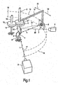
Fig. 1 , showing schematically - in perspective view - portions of a scatterometer. To explain the working principle, only some portions of the scatterometer are schematically shown, other portions are not shown. - The Fig. shows an incident light beam 1 originating from a
radiation source 2 and directed to the surface of a sample 4. Theradiation source 2 may generate a monochromatic radiation beam or a polychromatic radiation beam, for example white light. Sample 4 is attached to a sample support member 3, which is dull black to avoid undesired reflections, i.e. other reflections than the reflections from the surface of the sample 4. A (not shown) diaphragm in the light path of the incident radiation beam 1 can adjust the illuminated area of the surface of the sample 4. Thereby the diameter of the incident radiation beam 1 can be limited to a value between for example 2 mm and 12 mm. - The incident radiation beam 1 is reflected at the surface of the sample 4 and the
reflected radiation beam 5 projects on a flat screen 6 ascatter profile 7. The screen 6 is coated with a diffuse neutral gray coating to achieve an optimal image of the projectedscatter profile 7. - The
scatter profile 7 on screen 6 contains information about the surface structure of the sample 4, and can be recorded by acamera 9.Camera 9 is directed to amirror 10 and observes thescatter profile 7 on the screen 6 through saidmirror 10, as indicated bydashed lines mirror 10.) -
Radiation source 2 as well ascamera 9 is mounted in a fixed position. The sample support member 3 and themirror 10 are both attached to avertical pin 8, whichpin 8 can rotate around its longitudinal (vertical) axis. Therefore, the sample support member 3 and themirror 10 can both rotate around the said vertical axis ofpin 8 as a rotating unit. - Also the screen 6 can rotate around said vertical axis of
pin 8. To achieve such rotation, the screen 6 is connected by anarm 13 totooth wheel 12, whichtooth wheel 12 can rotate aroundpin 8.Arrows 22 indicate the movement ofarm 13, and dashedlines 19 indicate the movement of screen 6. - The angle at which the incident radiation beam 1 hits the surface of the sample 4 can be changed by rotating
pin 8, so that the sample support member 3 rotates around the vertical axis ofpin 8. Because theradiation source 2 is mounted at a fixed position, thereflection 5 of the incident radiation beam 1 is rotating with an angular velocity that is two times the angular velocity of the sample support member 3. Therefore, to receive the projectedscatter profile 7, the screen 6 has to rotate around the vertical axis ofpin 8 with an angular velocity which is two times the angular velocity ofpin 8 itself, with attached to it the sample support member 3. - Such difference in angular velocity can be achieved in many ways. According to the embodiment shown in the figure it is achieved by a simple toothed wheel mechanism. A first
toothed wheel 11 is connected topin 8.Toothed wheel 11 is in engagement with a secondtoothed wheel 14, having half the number of teeth, so that the angular velocity oftoothed wheel 14 is two times the angular velocity oftoothed wheel 11 andpin 8. A third toothed wheel IS is mounted on the samevertical pin 16 on whichtoothed wheel 14 is mounted, and it rotates with the same angular velocity astoothed wheel 14. Toothedwheel 14 is in engagement with a fourthtoothed wheel 12 on whicharm 13 is mounted.Toothed wheel 12 can rotate aroundpin 8 and will also have an angular velocity of two times the angular velocity ofpin 8, since toothedwheel 15 andtoothed wheel 12 have the same number of teeth. - It will be clear from the figure that by rotating the sample support member 3 over 90°, the screen 6 will rotate over 180°, as indicated by the
dashed lines scatter profile 7 is constantly projected on screen 6. Thecamera 9 has a fixed position and is directed tomirror 10, as is indicated bydashed line 20. Becausemirror 10 rotates together with support member 3, the camera will constantly observe the screen 6, as is indicated by dashedline 21. - The described embodiment of the scatterometer is merely an example; a great many other embodiments are possible.
Claims (7)
- A scatterometer comprising a source for providing an incident radiation beam to be directed to the surface of a sample, a support member for carrying said sample, means for directing said incident radiation beam at different angles towards the surface of the sample carried by the support member, a screen for receiving the reflection of the incident radiation beam, and a camera for recording the scatter profile as projected on said screen by the reflected radiation beam, whereby the camera is mounted in a fixed position and observes the front side of the screen on which radiation from the sample is incident through a mirror, characterized by means for moving the screen and thereby keeping it in the reflected radiation beam, and by means for moving the mirror for keeping the camera directed to the moving screen.
- A scatterometer as claimed in claim 1, characterized in that the screen is substantial flat.
- A scatterometer as claimed in any one of the preceding claims, characterized in that the source for providing an incident radiation beam is mounted in a fixed position and in that the support member can rotate around an axis substantial perpendicular with respect to the direction of said incident radiation beam.
- A scatterometer as claimed in claim 3, characterized in that the screen can rotate around substantially the same axis, whereby its angular velocity is two times the angular velocity of the support member.
- A scatterometer as claimed in claim 3 or 4, characterized in that the mirror can rotate substantially around said same axis with an angular velocity similar to the angular velocity of the support member.
- A scatterometer as claimed in claim 5, characterized in that the support member and said mirror are attached to a unit rotating around said axis, whereby said screen is connected to said unit, whereby it can rotate around said axis with a different angular velocity.
- A method for inspecting a surface of a sample carried by a support member, whereby a radiation source provides an incident radiation beam being directed towards the surface of a sample carried by the support member at different angles, whereby a screen receives the reflected radiation beam, and whereby a camera records the scatter profile as projected on the front side of said screen on which radiation from the sample is incident, whereby the camera is mounted in a fixed position and observes the screen through a mirror, characterized in that the screen is moved to keep it in the reflected radiation beam, and whereby the mirror is moved for keeping the camera directed to the moving screen.
Priority Applications (1)
| Application Number | Priority Date | Filing Date | Title |
|---|---|---|---|
| EP04712134A EP1599720B1 (en) | 2003-02-28 | 2004-02-18 | A scatterometer and a method for inspecting a surface |
Applications Claiming Priority (4)
| Application Number | Priority Date | Filing Date | Title |
|---|---|---|---|
| EP03100511 | 2003-02-28 | ||
| EP03100511 | 2003-02-28 | ||
| EP04712134A EP1599720B1 (en) | 2003-02-28 | 2004-02-18 | A scatterometer and a method for inspecting a surface |
| PCT/IB2004/050125 WO2004077033A1 (en) | 2003-02-28 | 2004-02-18 | A scatterometer and a method for inspecting a surface |
Publications (2)
| Publication Number | Publication Date |
|---|---|
| EP1599720A1 EP1599720A1 (en) | 2005-11-30 |
| EP1599720B1 true EP1599720B1 (en) | 2010-05-05 |
Family
ID=32921621
Family Applications (1)
| Application Number | Title | Priority Date | Filing Date |
|---|---|---|---|
| EP04712134A Expired - Lifetime EP1599720B1 (en) | 2003-02-28 | 2004-02-18 | A scatterometer and a method for inspecting a surface |
Country Status (7)
| Country | Link |
|---|---|
| US (1) | US7248368B2 (en) |
| EP (1) | EP1599720B1 (en) |
| JP (1) | JP4824541B2 (en) |
| CN (1) | CN1756948B (en) |
| AT (1) | ATE467114T1 (en) |
| DE (1) | DE602004027006D1 (en) |
| WO (1) | WO2004077033A1 (en) |
Families Citing this family (9)
| Publication number | Priority date | Publication date | Assignee | Title |
|---|---|---|---|---|
| CN100460861C (en) * | 2005-08-01 | 2009-02-11 | 中国科学院化学研究所 | Time-resolved two-dimensional laser light scattering instrument with both large and small angles |
| US7554665B2 (en) | 2005-08-15 | 2009-06-30 | Koninklijke Philips Electronics N.V. | Dual beam set-up for parousiameter |
| EP1966592A1 (en) | 2005-12-23 | 2008-09-10 | Koninklijke Philips Electronics N.V. | Optical measurement device |
| WO2007119202A1 (en) | 2006-04-18 | 2007-10-25 | Koninklijke Philips Electronics N.V. | Optical measurement device |
| WO2007119199A1 (en) | 2006-04-18 | 2007-10-25 | Koninklijke Philips Electronics N.V. | Optical measurement device |
| JP5411698B2 (en) * | 2006-10-05 | 2014-02-12 | コーニンクレッカ フィリップス エヌ ヴェ | Apparatus and method for observing the surface of a sample |
| CN102419315B (en) * | 2011-09-08 | 2015-09-30 | 苏州汉朗光电有限公司 | Smectic liquid crystal space scattering measurement method and device |
| FR3061301B1 (en) * | 2016-12-26 | 2020-09-04 | Commissariat Energie Atomique | OBJECT OBSERVATION PROCESS |
| JP7069328B2 (en) * | 2018-09-06 | 2022-05-17 | 日立Astemo株式会社 | Surface measurement method, component manufacturing method, component inspection method and component measuring device |
Family Cites Families (10)
| Publication number | Priority date | Publication date | Assignee | Title |
|---|---|---|---|---|
| GB2159271B (en) * | 1984-04-27 | 1988-05-18 | Nissan Motor | Surface flaw detecting method and apparatus |
| JPS60228910A (en) | 1984-04-27 | 1985-11-14 | Nissan Motor Co Ltd | Surface defect inspector |
| DE3731171A1 (en) * | 1987-09-17 | 1989-03-30 | Gerd Prof Selbach | Notchiness measuring instrument |
| US5241369A (en) * | 1990-10-01 | 1993-08-31 | Mcneil John R | Two-dimensional optical scatterometer apparatus and process |
| DE4343832A1 (en) * | 1993-12-22 | 1995-06-29 | Bayer Ag | Substituted 1-arylpyrazoles |
| IL113428A0 (en) * | 1995-04-20 | 1995-07-31 | Yissum Res Dev Co | Glossmeter |
| US5880843A (en) | 1997-09-03 | 1999-03-09 | Vitro Flotado, S.A. De C.V. | Apparatus and method for determining the optical distortion of a transparent substrate |
| KR100849370B1 (en) * | 1998-12-21 | 2008-07-31 | 코닌클리케 필립스 일렉트로닉스 엔.브이. | Scatterometer |
| DE19954183C2 (en) * | 1999-11-08 | 2003-07-31 | Autronic Melchers Gmbh | Method and device for measuring and evaluating the scattering behavior of surfaces |
| AUPR420201A0 (en) * | 2001-04-04 | 2001-05-03 | Varian Australia Pty Ltd | Measuring specular reflectance of a sample |
-
2004
- 2004-02-18 AT AT04712134T patent/ATE467114T1/en not_active IP Right Cessation
- 2004-02-18 EP EP04712134A patent/EP1599720B1/en not_active Expired - Lifetime
- 2004-02-18 CN CN200480005537.1A patent/CN1756948B/en not_active Expired - Fee Related
- 2004-02-18 WO PCT/IB2004/050125 patent/WO2004077033A1/en not_active Ceased
- 2004-02-18 DE DE602004027006T patent/DE602004027006D1/en not_active Expired - Lifetime
- 2004-02-18 US US10/546,313 patent/US7248368B2/en not_active Expired - Lifetime
- 2004-02-18 JP JP2006502599A patent/JP4824541B2/en not_active Expired - Fee Related
Also Published As
| Publication number | Publication date |
|---|---|
| JP2006519380A (en) | 2006-08-24 |
| CN1756948B (en) | 2010-05-26 |
| DE602004027006D1 (en) | 2010-06-17 |
| JP4824541B2 (en) | 2011-11-30 |
| ATE467114T1 (en) | 2010-05-15 |
| WO2004077033A1 (en) | 2004-09-10 |
| CN1756948A (en) | 2006-04-05 |
| EP1599720A1 (en) | 2005-11-30 |
| US7248368B2 (en) | 2007-07-24 |
| US20060066862A1 (en) | 2006-03-30 |
Similar Documents
| Publication | Publication Date | Title |
|---|---|---|
| KR101256390B1 (en) | Optical inspection of test surfaces | |
| EP2291606B1 (en) | Optical inspection probe | |
| EP1599720B1 (en) | A scatterometer and a method for inspecting a surface | |
| US6577397B1 (en) | Scatterometer | |
| JP5027946B1 (en) | Inspection system | |
| JP5107921B2 (en) | Dual beam setup for scatterometer | |
| KR20100090281A (en) | An optical device for observing millimetric or submillimetric structural details of an object with specular behaviour | |
| JP6584454B2 (en) | Image processing apparatus and method | |
| US6271963B1 (en) | Microscope illuminator for cylindrical objects | |
| US20040114035A1 (en) | Focusing panel illumination method and apparatus | |
| JP2018189517A (en) | Measuring device and article manufacturing method | |
| Isasi-Andrieu et al. | Deflectometry setup definition for automatic chrome surface inspection |
Legal Events
| Date | Code | Title | Description |
|---|---|---|---|
| PUAI | Public reference made under article 153(3) epc to a published international application that has entered the european phase |
Free format text: ORIGINAL CODE: 0009012 |
|
| 17P | Request for examination filed |
Effective date: 20050928 |
|
| AK | Designated contracting states |
Kind code of ref document: A1 Designated state(s): AT BE BG CH CY CZ DE DK EE ES FI FR GB GR HU IE IT LI LU MC NL PT RO SE SI SK TR |
|
| AX | Request for extension of the european patent |
Extension state: AL LT LV MK |
|
| DAX | Request for extension of the european patent (deleted) | ||
| 17Q | First examination report despatched |
Effective date: 20061122 |
|
| GRAP | Despatch of communication of intention to grant a patent |
Free format text: ORIGINAL CODE: EPIDOSNIGR1 |
|
| GRAS | Grant fee paid |
Free format text: ORIGINAL CODE: EPIDOSNIGR3 |
|
| GRAA | (expected) grant |
Free format text: ORIGINAL CODE: 0009210 |
|
| AK | Designated contracting states |
Kind code of ref document: B1 Designated state(s): AT BE BG CH CY CZ DE DK EE ES FI FR GB GR HU IE IT LI LU MC NL PT RO SE SI SK TR |
|
| REG | Reference to a national code |
Ref country code: GB Ref legal event code: FG4D |
|
| REG | Reference to a national code |
Ref country code: CH Ref legal event code: EP |
|
| REG | Reference to a national code |
Ref country code: IE Ref legal event code: FG4D |
|
| REF | Corresponds to: |
Ref document number: 602004027006 Country of ref document: DE Date of ref document: 20100617 Kind code of ref document: P |
|
| REG | Reference to a national code |
Ref country code: NL Ref legal event code: VDEP Effective date: 20100505 |
|
| PG25 | Lapsed in a contracting state [announced via postgrant information from national office to epo] |
Ref country code: ES Free format text: LAPSE BECAUSE OF FAILURE TO SUBMIT A TRANSLATION OF THE DESCRIPTION OR TO PAY THE FEE WITHIN THE PRESCRIBED TIME-LIMIT Effective date: 20100816 Ref country code: NL Free format text: LAPSE BECAUSE OF FAILURE TO SUBMIT A TRANSLATION OF THE DESCRIPTION OR TO PAY THE FEE WITHIN THE PRESCRIBED TIME-LIMIT Effective date: 20100505 Ref country code: SE Free format text: LAPSE BECAUSE OF FAILURE TO SUBMIT A TRANSLATION OF THE DESCRIPTION OR TO PAY THE FEE WITHIN THE PRESCRIBED TIME-LIMIT Effective date: 20100505 |
|
| PG25 | Lapsed in a contracting state [announced via postgrant information from national office to epo] |
Ref country code: SI Free format text: LAPSE BECAUSE OF FAILURE TO SUBMIT A TRANSLATION OF THE DESCRIPTION OR TO PAY THE FEE WITHIN THE PRESCRIBED TIME-LIMIT Effective date: 20100505 Ref country code: FI Free format text: LAPSE BECAUSE OF FAILURE TO SUBMIT A TRANSLATION OF THE DESCRIPTION OR TO PAY THE FEE WITHIN THE PRESCRIBED TIME-LIMIT Effective date: 20100505 Ref country code: AT Free format text: LAPSE BECAUSE OF FAILURE TO SUBMIT A TRANSLATION OF THE DESCRIPTION OR TO PAY THE FEE WITHIN THE PRESCRIBED TIME-LIMIT Effective date: 20100505 |
|
| PG25 | Lapsed in a contracting state [announced via postgrant information from national office to epo] |
Ref country code: GR Free format text: LAPSE BECAUSE OF FAILURE TO SUBMIT A TRANSLATION OF THE DESCRIPTION OR TO PAY THE FEE WITHIN THE PRESCRIBED TIME-LIMIT Effective date: 20100806 Ref country code: CY Free format text: LAPSE BECAUSE OF FAILURE TO SUBMIT A TRANSLATION OF THE DESCRIPTION OR TO PAY THE FEE WITHIN THE PRESCRIBED TIME-LIMIT Effective date: 20100505 |
|
| PG25 | Lapsed in a contracting state [announced via postgrant information from national office to epo] |
Ref country code: EE Free format text: LAPSE BECAUSE OF FAILURE TO SUBMIT A TRANSLATION OF THE DESCRIPTION OR TO PAY THE FEE WITHIN THE PRESCRIBED TIME-LIMIT Effective date: 20100505 Ref country code: PT Free format text: LAPSE BECAUSE OF FAILURE TO SUBMIT A TRANSLATION OF THE DESCRIPTION OR TO PAY THE FEE WITHIN THE PRESCRIBED TIME-LIMIT Effective date: 20100906 Ref country code: DK Free format text: LAPSE BECAUSE OF FAILURE TO SUBMIT A TRANSLATION OF THE DESCRIPTION OR TO PAY THE FEE WITHIN THE PRESCRIBED TIME-LIMIT Effective date: 20100505 |
|
| PG25 | Lapsed in a contracting state [announced via postgrant information from national office to epo] |
Ref country code: BE Free format text: LAPSE BECAUSE OF FAILURE TO SUBMIT A TRANSLATION OF THE DESCRIPTION OR TO PAY THE FEE WITHIN THE PRESCRIBED TIME-LIMIT Effective date: 20100505 Ref country code: RO Free format text: LAPSE BECAUSE OF FAILURE TO SUBMIT A TRANSLATION OF THE DESCRIPTION OR TO PAY THE FEE WITHIN THE PRESCRIBED TIME-LIMIT Effective date: 20100505 Ref country code: SK Free format text: LAPSE BECAUSE OF FAILURE TO SUBMIT A TRANSLATION OF THE DESCRIPTION OR TO PAY THE FEE WITHIN THE PRESCRIBED TIME-LIMIT Effective date: 20100505 Ref country code: CZ Free format text: LAPSE BECAUSE OF FAILURE TO SUBMIT A TRANSLATION OF THE DESCRIPTION OR TO PAY THE FEE WITHIN THE PRESCRIBED TIME-LIMIT Effective date: 20100505 |
|
| PLBE | No opposition filed within time limit |
Free format text: ORIGINAL CODE: 0009261 |
|
| STAA | Information on the status of an ep patent application or granted ep patent |
Free format text: STATUS: NO OPPOSITION FILED WITHIN TIME LIMIT |
|
| PG25 | Lapsed in a contracting state [announced via postgrant information from national office to epo] |
Ref country code: IT Free format text: LAPSE BECAUSE OF FAILURE TO SUBMIT A TRANSLATION OF THE DESCRIPTION OR TO PAY THE FEE WITHIN THE PRESCRIBED TIME-LIMIT Effective date: 20100505 |
|
| 26N | No opposition filed |
Effective date: 20110208 |
|
| REG | Reference to a national code |
Ref country code: DE Ref legal event code: R097 Ref document number: 602004027006 Country of ref document: DE Effective date: 20110207 |
|
| PG25 | Lapsed in a contracting state [announced via postgrant information from national office to epo] |
Ref country code: MC Free format text: LAPSE BECAUSE OF NON-PAYMENT OF DUE FEES Effective date: 20110228 |
|
| REG | Reference to a national code |
Ref country code: CH Ref legal event code: PL |
|
| PG25 | Lapsed in a contracting state [announced via postgrant information from national office to epo] |
Ref country code: LI Free format text: LAPSE BECAUSE OF NON-PAYMENT OF DUE FEES Effective date: 20110228 Ref country code: CH Free format text: LAPSE BECAUSE OF NON-PAYMENT OF DUE FEES Effective date: 20110228 |
|
| REG | Reference to a national code |
Ref country code: IE Ref legal event code: MM4A |
|
| PG25 | Lapsed in a contracting state [announced via postgrant information from national office to epo] |
Ref country code: IE Free format text: LAPSE BECAUSE OF NON-PAYMENT OF DUE FEES Effective date: 20110218 |
|
| PG25 | Lapsed in a contracting state [announced via postgrant information from national office to epo] |
Ref country code: LU Free format text: LAPSE BECAUSE OF NON-PAYMENT OF DUE FEES Effective date: 20110218 |
|
| PG25 | Lapsed in a contracting state [announced via postgrant information from national office to epo] |
Ref country code: BG Free format text: LAPSE BECAUSE OF FAILURE TO SUBMIT A TRANSLATION OF THE DESCRIPTION OR TO PAY THE FEE WITHIN THE PRESCRIBED TIME-LIMIT Effective date: 20100805 Ref country code: TR Free format text: LAPSE BECAUSE OF FAILURE TO SUBMIT A TRANSLATION OF THE DESCRIPTION OR TO PAY THE FEE WITHIN THE PRESCRIBED TIME-LIMIT Effective date: 20100505 |
|
| PG25 | Lapsed in a contracting state [announced via postgrant information from national office to epo] |
Ref country code: HU Free format text: LAPSE BECAUSE OF FAILURE TO SUBMIT A TRANSLATION OF THE DESCRIPTION OR TO PAY THE FEE WITHIN THE PRESCRIBED TIME-LIMIT Effective date: 20100505 |
|
| REG | Reference to a national code |
Ref country code: DE Ref legal event code: R082 Ref document number: 602004027006 Country of ref document: DE Representative=s name: VOLMER, GEORG, DIPL.-ING., DE |
|
| REG | Reference to a national code |
Ref country code: DE Ref legal event code: R082 Ref document number: 602004027006 Country of ref document: DE Representative=s name: MEISSNER, BOLTE & PARTNER GBR, DE Effective date: 20140328 Ref country code: DE Ref legal event code: R082 Ref document number: 602004027006 Country of ref document: DE Representative=s name: VOLMER, GEORG, DIPL.-ING., DE Effective date: 20140328 Ref country code: DE Ref legal event code: R081 Ref document number: 602004027006 Country of ref document: DE Owner name: KONINKLIJKE PHILIPS N.V., NL Free format text: FORMER OWNER: KONINKLIJKE PHILIPS ELECTRONICS N.V., EINDHOVEN, NL Effective date: 20140328 Ref country code: DE Ref legal event code: R082 Ref document number: 602004027006 Country of ref document: DE Representative=s name: MEISSNER BOLTE PATENTANWAELTE RECHTSANWAELTE P, DE Effective date: 20140328 |
|
| REG | Reference to a national code |
Ref country code: FR Ref legal event code: CA Effective date: 20141126 Ref country code: FR Ref legal event code: CD Owner name: KONINKLIJKE PHILIPS ELECTRONICS N.V., NL Effective date: 20141126 |
|
| REG | Reference to a national code |
Ref country code: FR Ref legal event code: PLFP Year of fee payment: 13 |
|
| REG | Reference to a national code |
Ref country code: DE Ref legal event code: R082 Ref document number: 602004027006 Country of ref document: DE Representative=s name: MEISSNER, BOLTE & PARTNER GBR, DE Ref country code: DE Ref legal event code: R082 Ref document number: 602004027006 Country of ref document: DE Representative=s name: MEISSNER BOLTE PATENTANWAELTE RECHTSANWAELTE P, DE |
|
| REG | Reference to a national code |
Ref country code: FR Ref legal event code: PLFP Year of fee payment: 14 |
|
| REG | Reference to a national code |
Ref country code: FR Ref legal event code: PLFP Year of fee payment: 15 |
|
| PGFP | Annual fee paid to national office [announced via postgrant information from national office to epo] |
Ref country code: GB Payment date: 20180227 Year of fee payment: 15 |
|
| PGFP | Annual fee paid to national office [announced via postgrant information from national office to epo] |
Ref country code: FR Payment date: 20180227 Year of fee payment: 15 |
|
| PGFP | Annual fee paid to national office [announced via postgrant information from national office to epo] |
Ref country code: DE Payment date: 20180430 Year of fee payment: 15 |
|
| REG | Reference to a national code |
Ref country code: DE Ref legal event code: R119 Ref document number: 602004027006 Country of ref document: DE |
|
| GBPC | Gb: european patent ceased through non-payment of renewal fee |
Effective date: 20190218 |
|
| PG25 | Lapsed in a contracting state [announced via postgrant information from national office to epo] |
Ref country code: DE Free format text: LAPSE BECAUSE OF NON-PAYMENT OF DUE FEES Effective date: 20190903 Ref country code: GB Free format text: LAPSE BECAUSE OF NON-PAYMENT OF DUE FEES Effective date: 20190218 |
|
| PG25 | Lapsed in a contracting state [announced via postgrant information from national office to epo] |
Ref country code: FR Free format text: LAPSE BECAUSE OF NON-PAYMENT OF DUE FEES Effective date: 20190228 |