JP2018189517A - Measurement device and method for manufacturing articles - Google Patents
Measurement device and method for manufacturing articles Download PDFInfo
- Publication number
- JP2018189517A JP2018189517A JP2017092525A JP2017092525A JP2018189517A JP 2018189517 A JP2018189517 A JP 2018189517A JP 2017092525 A JP2017092525 A JP 2017092525A JP 2017092525 A JP2017092525 A JP 2017092525A JP 2018189517 A JP2018189517 A JP 2018189517A
- Authority
- JP
- Japan
- Prior art keywords
- light
- reflecting surface
- measuring apparatus
- mirror
- unit
- Prior art date
- Legal status (The legal status is an assumption and is not a legal conclusion. Google has not performed a legal analysis and makes no representation as to the accuracy of the status listed.)
- Pending
Links
Images


Abstract
Description
本発明は、計測装置、および物品製造方法に関する。 The present invention relates to a measuring device and an article manufacturing method.
被検面の反射特性(光沢度、ヘイズ値など)を計測する計測装置が知られている。特許文献1は、被検面の光沢度を計測する装置を開示している。
A measuring device for measuring the reflection characteristics (glossiness, haze value, etc.) of a surface to be measured is known.
被検面に対する光の入射角度ごとに反射特性を計測するのに、光源および反射光を検出するセンサを複数組設けたり、光源およびセンサを移動させる機構を設けたりするのでは、計測装置のサイズの点で不利となりうる。 To measure the reflection characteristics for each incident angle of light with respect to the surface to be measured, it is necessary to provide multiple sets of light sources and sensors for detecting reflected light, or to provide a mechanism for moving the light sources and sensors. Can be disadvantageous.
本発明は、例えば、サイズの点で有利な計測装置を提供することを目的とする。 An object of the present invention is to provide a measuring device that is advantageous in terms of size, for example.
上記課題を解決するために、本発明は、光源からの光で被検面を照明する照明部を有し、照明部により照明された被検面からの反射光に基づいて被検面の反射特性を計測する計測装置であって、照明部は、第1反射面を有する第1ミラー部と、第2反射面を有する第2ミラー部と、を有し、第2反射面は、被検面上の点を焦点とする楕円または放物線上にあり、第1反射面は、光が、第2反射面を介して、点に、互いに異なる複数の入射角度のうちのいずれかで選択的に入射するように可動である、ことを特徴とする。 In order to solve the above problems, the present invention has an illumination unit that illuminates a test surface with light from a light source, and reflects the test surface based on reflected light from the test surface illuminated by the illumination unit. A measurement device for measuring characteristics, wherein the illumination unit includes a first mirror unit having a first reflection surface and a second mirror unit having a second reflection surface, and the second reflection surface is a test object. The first reflecting surface is selectively on at one of a plurality of incident angles different from each other via the second reflecting surface. The first reflecting surface is on an ellipse or a parabola with a point on the surface as a focal point. It is movable so that it may enter.
本発明によれば、例えば、サイズの点で有利な計測装置を提供することができる。 According to the present invention, for example, a measuring device advantageous in terms of size can be provided.
以下、本発明を実施するための形態について図面などを参照して説明する。なお、各図面において、同一の部材ないし要素については同一の参照番号を付し、重複する説明は省略する。
[第1実施形態]
Hereinafter, embodiments for carrying out the present invention will be described with reference to the drawings. In addition, in each drawing, the same reference number is attached | subjected about the same member thru | or element, and the overlapping description is abbreviate | omitted.
[First Embodiment]
<計測装置>
図1は、本実施形態に係る計測装置100の構成を示す図である。計測装置100は、被検物Wの被検面に対して複数の角度で光を照射し、被検面から複数の反射角度で反射された反射光を受光する。計測装置100は、照射角度、受光角度および受光した光の光強度に関する情報に基づいて反射特性を求める。本実施形態において、照射角度および受光角度の基準は、被検面の垂線とする。
<Measurement device>
FIG. 1 is a diagram illustrating a configuration of a
反射特性は、例えば、光沢度、ヘイズ値、写像性、BRDF(Bidirectional Reflectance Distribution Function:双方向反射率分布関数)を含む。計測装置100は、照明部110、受光部120、検出部130および、処理部140を有する。
The reflection characteristics include, for example, glossiness, haze value, image clarity, and BRDF (Bidirectional Reflection Distribution Function). The
(照明部)
照明部110は、電源111と、光源112と、レンズ113と、第1ミラー部114と、第2ミラー部115と、を含む。照明部110は、被検物Wの被検面を複数の角度で照明する。電源111は、光源112に駆動電流を出力する。
(Lighting part)
The
本実施形態では、光源112として、白色LEDを用いる。その他、白熱ランプ、ファイバレーザまたは半導体レーザ等を用いてもよい。特定の色に関する情報を得たい場合は、特定の波長を有する半導体レーザ等を用いうる。複数の異なる単一波長を有する光源を切替えて使用してもよい。
In the present embodiment, a white LED is used as the
光源112から出力された光は、レンズ113により平行ビームにされ、第1ミラー部114に入射する。第1ミラー部114に入射した光は、第1ミラー部114の反射面(第1反射面という。)で反射され、第2ミラー部115の反射面(第2反射面)に入射する。第2反射面で反射された光は、被検面に照射される。
The light output from the
第1反射面は、光源から出力された光が、第2反射面を介して、被検面上の点f2に、互いに異なる複数の入射角度のうちのいずれかで選択的に入射するように可動である。第1ミラー部114は、例えば、ガルバノミラーであり、第1反射面を有する平面ミラーと、第1反射面を移動させる照明側駆動部1141と、を有する。照明側駆動部1141は、第1反射面を第1反射面に平行な軸を中心に回転させる。照明側駆動部1141により反射面を移動させることで、照射角度が調整される。
The first reflective surface, light outputted from a light source, through the second reflecting surface, a point f 2 on the test surface, to selectively incident at any of a plurality of different incident angles It is movable. The
第1ミラー部114としては、ガルバノミラーに限らず、モータの回転軸にミラーを取りつけたものや、手動で角度を調整するミラーも用いうる。照明側駆動部1141と後述の受光側駆動部1221とを同期させて各反射面を回転させうる。
The
本実施形態では、第2ミラー部115は、平面ミラー115A、平面ミラー115Bおよび平面ミラー115Cを有する。第2ミラー部115が有する複数の平面ミラーのそれぞれの反射面(第2反射面)は、第1反射面上の点f1および、被検面上の点f2を焦点とする第1楕円E1の楕円上に配置される。
In the present embodiment, the
本実施形態では、平面ミラー115Aは、20度で被検面を照明し、平面ミラー115Bは、60度で被検面を照明し、平面ミラー115Cは、85度で被検面を照明する。
In the present embodiment, the
(受光部)
受光部120は、第3ミラー部121と、第4ミラー部122と、レンズ123と、を含む。レンズ123は、第4ミラー部122で反射された反射光の波面を調整し、検出部130へ調整した反射光を導く。
(Light receiving section)
The
本実施形態では、第3ミラー部121は、平面ミラー121A、平面ミラー121Bおよび平面ミラー121Cを有する。第3ミラー部121が有する複数の平面ミラーのそれぞれの反射面(第3反射面という。)は、第4ミラー部122の反射面(第4反射面)上の点f3および、被検面上の点f2を焦点とする第2楕円E2の楕円上に配置される。なお、第2楕円E2と第1楕円E1とは、同じ大きさに限られない。同じ大きさの場合は、設計が同じ平面ミラーの光学部品を利用することが可能となる。異なる大きさの場合は、測定対象に応じた装置の形状に設計することが可能となる。
In the present embodiment, the
本実施形態では、平面ミラー121Aは、20度の反射光を受け、平面ミラー121Bは、60度の反射光を受け、平面ミラー115Cは、85度の反射光を受ける。なお、照射角度と受光角度とは一致していなくとも良い。例えば、60度の照射角度で被検面を照明した光の反射光を85度の受光角度で受光してもよい。
In the present embodiment, the
第4ミラー部122は、反射光を、第3反射面を介して、被検面上の点f2から、互いに異なる複数の反射角度のうちのいずれかで選択的に受けるように、第4反射面を回転させる。第4ミラー部122は、例えば、ガルバノミラーであり、第4反射面を有する平面ミラーと、第4反射面を移動させる受光側駆動部1221と、を有する。受光側駆動部1221は、第4反射面を第4反射面に平行な軸を中心に回転させる。受光側駆動部1221により反射面を移動させることで、受光角度が調整される。第4ミラー部122も、ガルバノミラー以外の駆動部を備えたミラーを用いうる。
The
(検出部および処理部)
検出部130は、反射光を受ける検出面を備え、検出面における光強度を検出する。検出部130としては、例えば、ラインセンサやフォトディテクタなどの二次元センサを用いうる。検出部130によって検出された光強度に関する信号は処理部140へ出力される。
(Detection unit and processing unit)
The
処理部140は、照明側駆動部1141および受光側駆動部1221の制御情報を保持し、各駆動部を制御しうる。制御情報は、不図示の入力部により外部から入力されうる。処理部140は、受信した信号、照射角度および受光角度に基づいて被検面の反射特性を求める。
The
以上の通り、本実施形態の計測装置100は、光源または検出部(センサ)を増やしたり、移動させたりすることなく、複数の照射角度および受光角度で被検面の反射特性を計測できる。つまり、本実施形態の計測装置100は、例えば、装置サイズの点で有利である。
[第2実施形態]
As described above, the measuring
[Second Embodiment]
第1実施形態では、第2ミラー部115および第3ミラー部121に、複数の平面ミラーを用いていた。本実施形態では、複数の平面ミラーの代わりに反射面を楕円面とするひとつの楕円ミラーを用いて光学部材の数を第1実施形態に比べて少なくすることができる。図2は、本実施形態の計測装置200の構成を示す図である。計測装置200の照明部210は、楕円ミラーの第2ミラー部215を有する。また、受光部220は、楕円ミラーの第3ミラー部221を有する。本実施形態の計測装置200によれば、第1反射面の回転により照明光を回転させることで任意の照射角度および受光角度での計測が可能となり、また、第1実施形態と同様の効果を得られる。なお、照明部および受光部のうち、いずれか一方に楕円ミラーを用いてもよい。また、楕円ミラーと平面ミラーとを併用してもよい。
[第3実施形態]
In the first embodiment, a plurality of plane mirrors are used for the
[Third Embodiment]
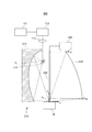
受光部に、反射面を放物線上に有する放物面ミラーを用いてもよい。この場合、受光部側のミラーを削減できる。図3は、本実施形態の計測装置300の構成を示す図である。計測装置300は、放物面ミラーである受光部320と、検出部330と、を有する。受光部320の放物面ミラーの焦点は点f2と一致している。なお、反射面を放物線上にある複数の平面としてもよい。
A parabolic mirror having a reflecting surface on a parabola may be used for the light receiving unit. In this case, the mirror on the light receiving unit side can be reduced. FIG. 3 is a diagram illustrating a configuration of the
検出部330は、受光部320から反射された平行光を受光する位置に配置される。本実施形態では、検出部330として、1ピクセルの大きさが24μm×24μmで、ピクセル数が512×512ピクセルであり、全体のサイズは12.3×12.3mmである二次元センサを用いる。照射角度を10度〜85度の範囲とする場合、放物面ミラーの形状は以下の説明のとおり決定される。
The
点f2を原点とし、被検面に平行な軸をx軸、垂直な軸をy軸とする。そして、被検面から高さ8.85mmの位置に検出部330の最下辺が来るようにする。被検面から85度の方向に反射した光が受光部320に当たる位置P85のx座標x85は、位置P85のy座標を10mmとすると、以下の数式(1)で求められる。
Point f 2 as the origin, x axis parallel to the test surface, an axis perpendicular to the y-axis. Then, the lowermost side of the

数式(1)より、位置P85のxy座標は、(114.3、10)となる。検出部330の使用領域を10mm×10mmとして、被検面から10度の方向に反射した光が受光部320に当たる位置P10のy座標を20mmとする。位置P10のx座標x10は、以下の数式(2)で求められる。
From Equation (1), xy coordinates of the position P 85 is (114.3,10). The use area of the
数式(2)より、位置P10のxy座標は、(3.5、20)となる。以上より、放物面ミラーの形状は、焦点(0、0)、P85、P10の条件を満たす放物線を有する放物面の形状である。x軸に対称な放物線とすると、放物線の式は以下の数式(3)となる。 From Equation (2), xy coordinates of the position P 10 is (3.5,20). From the above, the shape of the parabolic mirror is a parabolic shape having a parabola that satisfies the conditions of the focal point (0, 0), P 85 , and P 10 . Assuming that the parabola is symmetric with respect to the x-axis, the parabola formula is expressed by the following mathematical formula (3).
![]()
![]()
数式(3)で決定される形状の放物面ミラーを受光部320として用いることで、検出部330に垂直に光が入射される。なお、反射光の角度(受光角度)をψとすると、角度ψと検出部330のy座標の関係は次の数式(4)で表わされる。
By using a parabolic mirror having a shape determined by Equation (3) as the
数式(4)に基づいて、検出部330のセンサ上の座標から受光角度に関する情報を得ることができる。なお、本実施形態では放物面ミラーの放物面をx軸に対称な放物面としたが、x軸およびy軸を回転させた座標系における対照的な放物面でも良い。このような場合、二次元センサと放物面ミラーとの距離を変化させることが可能となる。また、センサの仕様の違いに応じて、大きさや形状の異なる放物線面ミラーを用いても良い。本実施形態の計測装置300も、第1実施形態と同様の効果を奏する。
[第4実施形態]
Based on Equation (4), information regarding the light reception angle can be obtained from the coordinates on the sensor of the
[Fourth Embodiment]
第3実施形態では、数式(4)に基づいて、検出部330のセンサ上の座標から受光角度に関する情報を得ることができた。本実施形態では、第2実施形態のような楕円ミラーを受光部に用い、かつ、検出部を第3実施形態と同様の配置とした場合に、検出部のセンサ上の座標を所定の一次関数に基づいてと受光角度に関する情報を得る。
In the third embodiment, information related to the light reception angle can be obtained from the coordinates on the sensor of the
第3ミラー部221の楕円ミラーの焦点の一方を点f2とし、他方を図3の検出部330上の点(y軸上の点)とする。楕円ミラーの反射面は、長径をb、短径をaとすると、数式(5)で表される。
One focus of the ellipse mirror of the
また、検出部330上の点のy座標は、数式(6)で表される。
Further, the y coordinate of the point on the
![]()
![]()
反射光が検出部330のセンサ面に対して垂直に入射すると仮定すると、楕円ミラー上の座標xは数式(7)である。φは、第3実施形態と同様の角度である。
![]()
![]()
これらの式を用いて、a、bおよびyの関係を求めると、以下のように表わされる。 Using these equations, the relationship between a, b, and y is obtained as follows.
上記数式に基づいて、検出部のセンサ上の座標と受光角度に関する情報とを対応付けることができる。
[第5実施形態]
Based on the above formula, the coordinates on the sensor of the detection unit can be associated with information on the light reception angle.
[Fifth Embodiment]
図4は、第5実施形態に係る計測装置500の構成を示す図である。本実施形態の計測装置500は、第3実施形態の計測装置300と比べ、受光部側の構成が異なる。計測装置500は、受光部520と、検出部530と、を有する。受光部520は、放物面ミラー521と、折り返しミラー522と、を含む。
FIG. 4 is a diagram illustrating a configuration of a
折り返しミラー522は、検出部530と放物面ミラー521との間の光路上に配置され、放物面ミラー521で反射された光の進む方向を受光部530に向かって、例えば、90度折り返す。なお、本実施形態の放物面ミラー521は、点f2を焦点とするが、第3実施形態とは異なる方向に入射光を反射させる。本実施形態によって、検出部530の厚みや配線などによって照射光の光路が妨げられることを回避することが可能となる。
[変形例]
The
[Modification]
なお、被検物面がコーティングや異物などにより層構造になっている場合や、漏れ光や装置内での多重反射等で迷光が生じる場合がある。この場合、アパーチャを検出部の前に配置することで迷光の影響を抑えうる。図5は、迷光の影響を抑える光学系の構成を示す図である。図5に示す通り、検出部640の検出面側に、検出面側から順に平行光レンズ630、アパーチャ620および集光レンズ610が配置される。
Note that the surface of the test object may have a layer structure due to a coating or foreign matter, or stray light may occur due to leakage light, multiple reflection within the apparatus, or the like. In this case, the influence of stray light can be suppressed by arranging the aperture in front of the detection unit. FIG. 5 is a diagram illustrating a configuration of an optical system that suppresses the influence of stray light. As shown in FIG. 5, a parallel
迷光は、被検面からの反射光(平行光)が集光レンズ610によって集光される点とは異なる点に集光される。そこで、アパーチャ620を通し、さらに平行光レンズ630を配置することで、迷光を低減することが可能となる。なお、本実施形態では集光レンズ610を用いたが、曲面ミラーによる反射レンズを用いてもよい。反射レンズを用いることで、収差の影響も低減できる。
The stray light is collected at a point different from the point where the reflected light (parallel light) from the test surface is collected by the
なお、被検物Wを囲むように受光部側に放物面ミラーをドーム状に配置してもよい。この配置によれば、全方位への反射光を受光しうる。 A parabolic mirror may be arranged in a dome shape on the light receiving part side so as to surround the test object W. According to this arrangement, reflected light in all directions can be received.
また、照明部側に放物面ミラーを用いてもよい。この場合、放物面ミラーに照射される光は、二次元のビームシフタによって光軸の平行性は保たれたまま、放物面ミラー上で走査される。さらに、光の波面を制御する光学系を用いて被検面に照射される光が平行光となるようにする。また、第1反射面の回転により光を並進させてもよい。 Moreover, you may use a parabolic mirror for the illumination part side. In this case, the light irradiated on the parabolic mirror is scanned on the parabolic mirror while the parallelism of the optical axis is maintained by the two-dimensional beam shifter. Furthermore, the optical system that controls the wavefront of the light is used so that the light irradiated onto the test surface becomes parallel light. Moreover, you may translate light by rotation of a 1st reflective surface.
被検物Wを囲むように照明部側に楕円球面ミラーをドーム状に配置してもよい。楕円球面ミラーに照射される光は、二次元ビームスキャナによって様々な方向へ走査される。さらに、光の波面を制御する光学系を用いて被検面に照射される光が平行光となるようにする。楕円球面の一方の焦点に二次元ビームスキャナが配置され、他方の焦点に被検面が配置される。 An elliptical spherical mirror may be arranged in a dome shape on the illumination unit side so as to surround the test object W. Light irradiated on the elliptical spherical mirror is scanned in various directions by a two-dimensional beam scanner. Furthermore, the optical system that controls the wavefront of the light is used so that the light irradiated onto the test surface becomes parallel light. A two-dimensional beam scanner is disposed at one focal point of the elliptical spherical surface, and a test surface is disposed at the other focal point.
(物品製造方法に係る実施形態)
以上に説明した実施形態に係る計測装置は、物品製造方法に使用しうる。当該物品製造方法は、当該計測装置を用いて物体の被検面の反射特性を計測する工程と、当該工程で当該反射特性を計測された物体を処理する工程と、を含みうる。当該処理は、例えば、加工、切断、検査、組付、および選別のうちの少なくともいずれか一つを含みうる。より具体的には、例えば、塗装された物体の表面の反射特性を計測し、得られた計測値をその基準値と比較する。当該比較の結果に基づいて、物体の選別を行う(例えば、計測値が許容範囲内に収まっていない場合、当該物体を不良と判断する)。または、当該比較の結果に基づいて、物体の塗装工程に塗装条件に係るフィードバックを行う。本実施形態の物品製造方法は、当該計測装置により物体の表面の反射特性を計測するため、従来の方法に比べて、物品の性能・品質・生産性・生産コストのうちの少なくとも1つにおいて有利である。
(Embodiment related to article manufacturing method)
The measuring device according to the embodiment described above can be used in an article manufacturing method. The article manufacturing method may include a step of measuring the reflection characteristic of the test surface of the object using the measuring device, and a step of processing the object whose reflection characteristic is measured in the step. The process can include, for example, at least one of processing, cutting, inspection, assembly, and selection. More specifically, for example, the reflection characteristic of the surface of the painted object is measured, and the obtained measurement value is compared with the reference value. Based on the result of the comparison, an object is selected (for example, if the measured value does not fall within the allowable range, the object is determined to be defective). Alternatively, based on the result of the comparison, feedback relating to the painting conditions is performed in the painting process of the object. Since the article manufacturing method of the present embodiment measures the reflection characteristics of the surface of an object with the measuring device, it is advantageous in at least one of the performance, quality, productivity, and production cost of the article compared to the conventional method. It is.
(その他の実施形態)
以上、本発明の実施の形態を説明してきたが、本発明はこれらの実施の形態に限定されず、その要旨の範囲内において様々な変更が可能である。
(Other embodiments)
As mentioned above, although embodiment of this invention has been described, this invention is not limited to these embodiment, A various change is possible within the range of the summary.
100 計測装置
110 照明部
114 第1ミラー部
1141 照明側駆動部
115 第2ミラー部
120 受光部
121 第3ミラー部
122 第4ミラー部
1222 受光側駆動部
130 検出部
140 処理部
DESCRIPTION OF
Claims (19)
前記照明部は、第1反射面を有する第1ミラー部と、第2反射面を有する第2ミラー部と、を有し、
前記第2反射面は、前記被検面上の点を焦点とする楕円上または放物線上にあり、
前記第1反射面は、前記光が、前記第2反射面を介して、前記点に、互いに異なる複数の入射角度のうちのいずれかで選択的に入射するように可動である、
ことを特徴とする計測装置。 A measuring device that includes an illuminating unit that illuminates a test surface with light from a light source, and that measures reflection characteristics of the test surface based on reflected light from the test surface illuminated by the illuminating unit; ,
The illumination unit includes a first mirror unit having a first reflection surface, and a second mirror unit having a second reflection surface,
The second reflecting surface is on an ellipse or a parabola with a point on the test surface as a focal point,
The first reflection surface is movable so that the light selectively enters the point through the second reflection surface at any one of a plurality of different incident angles.
A measuring device characterized by that.
前記検出面へ前記反射光を導く受光部と、を有し、
前記受光部は、第3反射面を有する第3ミラー部と、第4反射面を有する第4ミラー部と、を有し、
前記第3反射面は、前記点を焦点とする楕円上または放物線上にある、
ことを特徴とする請求項1乃至9のうちいずれか1項に記載の計測装置。 A detection unit that receives the reflected light, and detects a light intensity on the detection surface;
A light receiving portion for guiding the reflected light to the detection surface,
The light receiving unit includes a third mirror unit having a third reflecting surface, and a fourth mirror unit having a fourth reflecting surface,
The third reflecting surface is on an ellipse or a parabola with the point as a focus,
The measuring apparatus according to claim 1, wherein the measuring apparatus is one of the following.
前記反射光を前記検出面へ導く受光部と、を有し、
前記受光部は、第3反射面を有し、前記第3反射面は、前記点を焦点とする放物線上にある、
ことを特徴とする請求項1乃至9のうちいずれか1項に記載の計測装置。 A detection unit that receives the reflected light, and detects a light intensity on the detection surface;
A light receiving section for guiding the reflected light to the detection surface,
The light receiving unit has a third reflecting surface, and the third reflecting surface is on a parabola with the point as a focus.
The measuring apparatus according to claim 1, wherein the measuring apparatus is one of the following.
請求項1乃至18のうちいずれか1項に記載の計測装置を用いて物体の被検面の反射特性を計測し、
前記計測を行われた前記物体の処理を行って前記物品を製造する、
ことを特徴とする製造方法。
A method for manufacturing an article, comprising:
A reflection characteristic of an object surface to be measured is measured using the measurement device according to any one of claims 1 to 18,
The article is manufactured by processing the measured object.
The manufacturing method characterized by the above-mentioned.
Priority Applications (1)
| Application Number | Priority Date | Filing Date | Title |
|---|---|---|---|
| JP2017092525A JP2018189517A (en) | 2017-05-08 | 2017-05-08 | Measurement device and method for manufacturing articles |
Applications Claiming Priority (1)
| Application Number | Priority Date | Filing Date | Title |
|---|---|---|---|
| JP2017092525A JP2018189517A (en) | 2017-05-08 | 2017-05-08 | Measurement device and method for manufacturing articles |
Publications (2)
| Publication Number | Publication Date |
|---|---|
| JP2018189517A true JP2018189517A (en) | 2018-11-29 |
| JP2018189517A5 JP2018189517A5 (en) | 2020-07-02 |
Family
ID=64479658
Family Applications (1)
| Application Number | Title | Priority Date | Filing Date |
|---|---|---|---|
| JP2017092525A Pending JP2018189517A (en) | 2017-05-08 | 2017-05-08 | Measurement device and method for manufacturing articles |
Country Status (1)
| Country | Link |
|---|---|
| JP (1) | JP2018189517A (en) |
Cited By (1)
| Publication number | Priority date | Publication date | Assignee | Title |
|---|---|---|---|---|
| FR3087011A1 (en) * | 2018-10-08 | 2020-04-10 | Unity Semiconductor | DARK FIELD OPTICAL INSPECTION DEVICE |
Citations (7)
| Publication number | Priority date | Publication date | Assignee | Title |
|---|---|---|---|---|
| US4815858A (en) * | 1987-10-09 | 1989-03-28 | The United States Of America As Represented By The Secretary Of The Navy | Reflectometers |
| JP2000035363A (en) * | 1998-07-16 | 2000-02-02 | Nikon Corp | Detecting apparatus for optical characteristic |
| JP2004045065A (en) * | 2002-07-09 | 2004-02-12 | National Institute Of Advanced Industrial & Technology | Incident-angle-variable optical system for measuring absolute reflectivity and absolute transmissivity |
| JP2011069719A (en) * | 2009-09-25 | 2011-04-07 | Horiba Ltd | Photodetector and optical transmitter |
| JP2014211322A (en) * | 2013-04-17 | 2014-11-13 | 花王株式会社 | Optical characteristic measurement device |
| JP2015200664A (en) * | 2006-05-05 | 2015-11-12 | エージーシー・フラット・グラス・ノース・アメリカ, インコーポレイテッド | Device for angular colorimetry and method of the same |
| WO2017037948A1 (en) * | 2015-09-04 | 2017-03-09 | オリンパス株式会社 | Reflection characteristic measuring system |
-
2017
- 2017-05-08 JP JP2017092525A patent/JP2018189517A/en active Pending
Patent Citations (7)
| Publication number | Priority date | Publication date | Assignee | Title |
|---|---|---|---|---|
| US4815858A (en) * | 1987-10-09 | 1989-03-28 | The United States Of America As Represented By The Secretary Of The Navy | Reflectometers |
| JP2000035363A (en) * | 1998-07-16 | 2000-02-02 | Nikon Corp | Detecting apparatus for optical characteristic |
| JP2004045065A (en) * | 2002-07-09 | 2004-02-12 | National Institute Of Advanced Industrial & Technology | Incident-angle-variable optical system for measuring absolute reflectivity and absolute transmissivity |
| JP2015200664A (en) * | 2006-05-05 | 2015-11-12 | エージーシー・フラット・グラス・ノース・アメリカ, インコーポレイテッド | Device for angular colorimetry and method of the same |
| JP2011069719A (en) * | 2009-09-25 | 2011-04-07 | Horiba Ltd | Photodetector and optical transmitter |
| JP2014211322A (en) * | 2013-04-17 | 2014-11-13 | 花王株式会社 | Optical characteristic measurement device |
| WO2017037948A1 (en) * | 2015-09-04 | 2017-03-09 | オリンパス株式会社 | Reflection characteristic measuring system |
Cited By (2)
| Publication number | Priority date | Publication date | Assignee | Title |
|---|---|---|---|---|
| FR3087011A1 (en) * | 2018-10-08 | 2020-04-10 | Unity Semiconductor | DARK FIELD OPTICAL INSPECTION DEVICE |
| WO2020074800A1 (en) * | 2018-10-08 | 2020-04-16 | Unity Semiconductor | Dark-field optical inspecting device |
Similar Documents
| Publication | Publication Date | Title |
|---|---|---|
| US5894345A (en) | Optical method of detecting defect and apparatus used therein | |
| JP5895305B2 (en) | Inspection illumination device and inspection illumination method | |
| JP5489186B2 (en) | Surface inspection device | |
| JP5471477B2 (en) | Thread inspection equipment | |
| JPH05126748A (en) | Optical inspecting device | |
| US20080079935A1 (en) | Inspecting lighting head system and method of operation | |
| JP6895768B2 (en) | Defect inspection equipment and defect inspection method | |
| KR101525700B1 (en) | Apparatus for Examining Appearance of Chip Component | |
| KR20160004099A (en) | Defect inspecting apparatus | |
| JP2014240766A (en) | Surface inspection method and device | |
| CN108139205B (en) | Optical element characteristic measuring device | |
| US11486693B2 (en) | Measurement apparatus and measurement method | |
| JP2022049881A (en) | Optical device | |
| JP2018189517A (en) | Measurement device and method for manufacturing articles | |
| JP5294081B2 (en) | Glossy cylindrical surface shape inspection device | |
| KR100878425B1 (en) | Surface measurement apparatus | |
| JP2011134687A (en) | Lighting system | |
| JP2016114602A (en) | Surface shape measurement device, and defect determination device | |
| JP2009222614A (en) | Surface inspection apparatus | |
| EP0777850A1 (en) | Integral field lens illumination for video inspection | |
| JP5935266B2 (en) | Scratch defect inspection method and sheet manufacturing method | |
| CN212567282U (en) | Detection device and detection equipment | |
| KR20110133183A (en) | Inspecting machine for flat panel | |
| JP2022063522A (en) | Inspection device | |
| JP2009222629A (en) | Device for inspecting edge of object to be inspected |
Legal Events
| Date | Code | Title | Description |
|---|---|---|---|
| A521 | Request for written amendment filed |
Free format text: JAPANESE INTERMEDIATE CODE: A523 Effective date: 20200424 |
|
| A621 | Written request for application examination |
Free format text: JAPANESE INTERMEDIATE CODE: A621 Effective date: 20200424 |
|
| A977 | Report on retrieval |
Free format text: JAPANESE INTERMEDIATE CODE: A971007 Effective date: 20210226 |
|
| A131 | Notification of reasons for refusal |
Free format text: JAPANESE INTERMEDIATE CODE: A131 Effective date: 20210406 |
|
| A02 | Decision of refusal |
Free format text: JAPANESE INTERMEDIATE CODE: A02 Effective date: 20211026 |