EP1599080A2 - Pont thermique pour dissiper la chaleur d' un circuit de commande d' éléments radiants à fluide - Google Patents
Pont thermique pour dissiper la chaleur d' un circuit de commande d' éléments radiants à fluide Download PDFInfo
- Publication number
- EP1599080A2 EP1599080A2 EP05104170A EP05104170A EP1599080A2 EP 1599080 A2 EP1599080 A2 EP 1599080A2 EP 05104170 A EP05104170 A EP 05104170A EP 05104170 A EP05104170 A EP 05104170A EP 1599080 A2 EP1599080 A2 EP 1599080A2
- Authority
- EP
- European Patent Office
- Prior art keywords
- thermal bridge
- solid state
- case
- sleeve
- state switch
- Prior art date
- Legal status (The legal status is an assumption and is not a legal conclusion. Google has not performed a legal analysis and makes no representation as to the accuracy of the status listed.)
- Granted
Links
- 239000012530 fluid Substances 0.000 title claims abstract description 8
- 230000017525 heat dissipation Effects 0.000 title description 2
- 239000007787 solid Substances 0.000 claims abstract description 32
- 230000005540 biological transmission Effects 0.000 claims abstract description 4
- 239000004020 conductor Substances 0.000 claims abstract description 4
- 238000010079 rubber tapping Methods 0.000 claims description 2
- 230000037431 insertion Effects 0.000 abstract 1
- 238000003780 insertion Methods 0.000 abstract 1
- 230000008878 coupling Effects 0.000 description 6
- 238000010168 coupling process Methods 0.000 description 6
- 238000005859 coupling reaction Methods 0.000 description 6
- 238000001816 cooling Methods 0.000 description 3
- 239000006185 dispersion Substances 0.000 description 2
- 230000002265 prevention Effects 0.000 description 2
- 239000000428 dust Substances 0.000 description 1
- 238000010438 heat treatment Methods 0.000 description 1
- 230000008595 infiltration Effects 0.000 description 1
- 238000001764 infiltration Methods 0.000 description 1
- 238000009413 insulation Methods 0.000 description 1
- 238000004519 manufacturing process Methods 0.000 description 1
- 230000001105 regulatory effect Effects 0.000 description 1
- 238000000926 separation method Methods 0.000 description 1
- 238000009423 ventilation Methods 0.000 description 1
- XLYOFNOQVPJJNP-UHFFFAOYSA-N water Substances O XLYOFNOQVPJJNP-UHFFFAOYSA-N 0.000 description 1
Images

Classifications
-
- F—MECHANICAL ENGINEERING; LIGHTING; HEATING; WEAPONS; BLASTING
- F24—HEATING; RANGES; VENTILATING
- F24H—FLUID HEATERS, e.g. WATER OR AIR HEATERS, HAVING HEAT-GENERATING MEANS, e.g. HEAT PUMPS, IN GENERAL
- F24H9/00—Details
- F24H9/20—Arrangement or mounting of control or safety devices
-
- H—ELECTRICITY
- H05—ELECTRIC TECHNIQUES NOT OTHERWISE PROVIDED FOR
- H05K—PRINTED CIRCUITS; CASINGS OR CONSTRUCTIONAL DETAILS OF ELECTRIC APPARATUS; MANUFACTURE OF ASSEMBLAGES OF ELECTRICAL COMPONENTS
- H05K7/00—Constructional details common to different types of electric apparatus
- H05K7/20—Modifications to facilitate cooling, ventilating, or heating
-
- F—MECHANICAL ENGINEERING; LIGHTING; HEATING; WEAPONS; BLASTING
- F24—HEATING; RANGES; VENTILATING
- F24H—FLUID HEATERS, e.g. WATER OR AIR HEATERS, HAVING HEAT-GENERATING MEANS, e.g. HEAT PUMPS, IN GENERAL
- F24H3/00—Air heaters
- F24H3/002—Air heaters using electric energy supply
- F24H3/004—Air heaters using electric energy supply with a closed circuit for a heat transfer liquid
Definitions
- the present invention relates to a thermal bridge for dissipation of heat produced by solid state switches, generally TRIAC or SCR, which are present in control circuits of fluid radiant elements heated by electric heaters.
- solid state switches generally TRIAC or SCR
- the thermal bridge is associated to control circuits of radiators for heating rooms and/or napkins and towels.
- the carrier fluid is heated by proper heaters comprising a tubular body inserted in the body of the radiant element, having inside an electric resistance which is fed by the supply mains.
- the tubular body has at one end a tubular fixing sleeve to the body of the radiant element, through which the leads for connecting the electric resistance to the supply mains are passing.
- the control circuit regulating the temperature and the operation mode of the radiant element is well-known per se and comprises a solid state switch consisting of a bi-directional thyristor (TRIAC or SCR) and electronic control means suited to regulate tripping and closure of the switch.
- TRIAC bi-directional thyristor
- the control circuit is enclosed inside a case which is associated to the body of the radiant element and from which the heat produced by the switch during the operation must be properly and efficiently dissipated.
- the case is kept slightly open to let an air-flow pass for cooling the solid state switch.
- cooling occurs by natural ventilation and has the limitation which is generally insufficient to obtain the expected cooling.
- Another drawback consists in that the accident prevention rules are not respected because said rules state that the electric apparatus must be closed during the operation.
- the present invention aims at overcoming said drawbacks.
- the heat dissipated by the solid state switch does not exceed, in the most critical cases, the value of 10 watts constituting a power value absolutely negligible in comparison with the power of the resistance equipping the heater that generally has values between 500 and 2000 watts.
- the heat produced by the solid state switch is insufficient to increase the temperature of the fixing sleeve of the heater to the radiant element in view of the mass of said radiant element.
- the body of the solid state switch is physically connected to the tubular sleeve, the latter operates as a heat sink and allows to keep the switch temperature within values between 90 and 100°C, therefore below the critical value.
- the present invention intends to avoid the foregoing drawbacks making use of the above-mentioned considerations.
- a first object of the invention is to provide a physical connection between the solid state switch of a control circuit applicable to a fluid radiant element and the thermal dispersion means.
- Another object is to provide a connection according to the invention making easier and more efficient the dissipation of heat produced by the switch in comparison with the prior art dissipation systems.
- a further object is that the connection can be carried out inside the case containing the control circuit.
- a last but not least object is that the thermal bridge of the invention be easy to be manufactured and assembled.
- thermo bridge for transmission of heat produced by solid state switches of control circuits applicable to fluid radiant elements that, according to the main claim, comprises:
- fastening means for the switch inside the relevant housing are provided.
- the use of the thermal bridge of the invention allows a greater constructional simplification and a better thermal dispersion of the heat produced by the solid state switch.
- thermal bridge allows to keep the case containing the control circuit sealed, to the advantage of the accident prevention and operation safety.
- the thermal bridge of the invention is used for transmission of the heat produced during the operation of the solid state switch 2 of a control circuit, generally indicated with numeral 3, which is applied to fluid radiant elements, one of which is of the kind shown in two different views of figures 1 and 2 where it is generally indicated with numeral 4 .
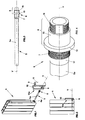
- a heater 5 is applied, shown also in Figure 3, which is formed by a tubular body 5a inserted in a housing 4a made in the body of the radiant element 4, and internally provided with an electric resistance not shown in the drawing, which is connected to the power supply mains.
- the tubular body 5 is fixed to the radiant element 4 through a tubular sleeve 6 that can be seen in detail and in isometric view in Figure 4, which is provided with fastening means to the radiant element, which consist of a thread 7 which is coupled to a corresponding opposite thread made in the seat 4a.
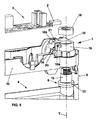
- the end portion 8 of the tubular sleeve 6 projecting from the housing 4a is arranged passing through a hole 9 of a case 10 which, as shown in figures 1 and 2, is fixed to the radiant element 4 and is closed by a lid 11.
- solid state switch means a bi-directional thyristor commonly referred to as TRIAC or SCR.
- the thermal bridge 1 consists of a collector body 12 made of thermally conductive material and arranged inside said case 10 where it is in contact with said at least one solid state switch 2 and said end portion 8 of said sleeve 6.
- connection means to the end portion 8 of the tubular sleeve 6 and housing means suited to receive the solid state switch 2 are defined.
- the connecting means consist of a tightening clamp 14, which is circumferentially coupled outside the cylindrical body 15 of the tubular sleeve 6, and of an end thread 16 substantially forming the outer side of said tubular body 6.
- annular shoulder 13 separates the cylindrical body 15 from the thread 7 coupling to the radiant body 4 and ending with a coupling fitting 17 to the tubular body 5a.
- the tightening clamp 14 consist of a slit ring 18 in the form of C, provided at the ends with a couple of opposite co-axial holes 18a receiving a screw, not shown in the drawing, tightening the ring 18 outside the cylindrical body 15 after the mutual coupling.
- the holes 18a are through holes in which a self tapping screw is received.
- a nut 19 coupled to the end thread 16 of the tubular element 6 is provided to keep the thermal bridge 1 constrained and avoid its axial separation along the axis Y after the assembly.
- the case 10 is provided with a detent 20 which is engaged against the upper surface 12a of the thermal bridge 1 after its coupling with the tubular element 6.
- the housing means receiving the switch 2 consist of a prismatic seat 21 recessed in the collector element 12 and provided with an internal profile matching the outer profile of the corresponding solid state switch 2.
- Locking of the switch 2 in the corresponding seat 21 may occur through locking means of any type, for instance screw means or spring means and according to the insulation degree to be carried out.
- the thermal bridge 1 In operation, to assemble the thermal bridge 1 first of all the heater 5 must be inserted in the radiant body 4 and then the end portion 8 of the tubular sleeve 6 must be coupled in the hole 9 of case 10 in which the control circuit 3 was previously installed.
- the ring 18 of the tightening clamp 14 is then fit with a sliding movement along the axis Y on the cylindrical body 15 of the tubular element 6 until the detent 20 snaps so that it is positioned on the surface 12a of the collector 12, as shown in Figure 6.
- the detent 20 prevents the rotation of the thermal bridge around the axis Y.
- the thermal bridge 1 is axially blocked through the nut 19 and radially on the cylindrical body 15 by tightening the screw coupled in the holes 18a.
- the solid state switch 2 must be arranged inside the corresponding seat 21 and then locked through the above-mentioned locking means.
- the sleeve therefore acts as a thermal collector to the mass formed by the radiant element.
Landscapes
- Engineering & Computer Science (AREA)
- Thermal Sciences (AREA)
- Physics & Mathematics (AREA)
- General Engineering & Computer Science (AREA)
- Combustion & Propulsion (AREA)
- Mechanical Engineering (AREA)
- Chemical & Material Sciences (AREA)
- Microelectronics & Electronic Packaging (AREA)
- Resistance Heating (AREA)
- Electric Stoves And Ranges (AREA)
- Central Heating Systems (AREA)
- Cooling Or The Like Of Electrical Apparatus (AREA)
- Cooling Or The Like Of Semiconductors Or Solid State Devices (AREA)
- Instantaneous Water Boilers, Portable Hot-Water Supply Apparatuses, And Control Of Portable Hot-Water Supply Apparatuses (AREA)
Applications Claiming Priority (2)
| Application Number | Priority Date | Filing Date | Title |
|---|---|---|---|
| IT000120A ITVI20040120A1 (it) | 2004-05-18 | 2004-05-18 | Ponte termico per la dissipazione del calore prodotto da circuiti di comando applicabili ad elementi radianti a fluido |
| ITVI20040120 | 2004-05-18 |
Publications (3)
| Publication Number | Publication Date |
|---|---|
| EP1599080A2 true EP1599080A2 (fr) | 2005-11-23 |
| EP1599080A3 EP1599080A3 (fr) | 2006-03-15 |
| EP1599080B1 EP1599080B1 (fr) | 2009-07-22 |
Family
ID=34939872
Family Applications (1)
| Application Number | Title | Priority Date | Filing Date |
|---|---|---|---|
| EP05104170A Expired - Lifetime EP1599080B1 (fr) | 2004-05-18 | 2005-05-18 | Pont thermique pour dissiper la chaleur d' un circuit de commande d' éléments radiants à fluide |
Country Status (5)
| Country | Link |
|---|---|
| EP (1) | EP1599080B1 (fr) |
| AT (1) | ATE437341T1 (fr) |
| DE (1) | DE602005015510D1 (fr) |
| ES (1) | ES2329380T3 (fr) |
| IT (1) | ITVI20040120A1 (fr) |
Cited By (3)
| Publication number | Priority date | Publication date | Assignee | Title |
|---|---|---|---|---|
| ITRM20090106A1 (it) * | 2009-03-10 | 2010-09-11 | I R C A S P A Ind Resistenz E Corazzate E | Radiatore, in particolare per il riscaldamento di ambienti |
| IT202200008582A1 (it) * | 2022-04-29 | 2023-10-29 | Ht S P A | Dispositivo riscaldante per fluidi |
| GB2640834A (en) * | 2024-04-29 | 2025-11-12 | Octopus Energy Heating Ltd | Methods and systems and apparatus to support reduced energy and water usage |
Citations (1)
| Publication number | Priority date | Publication date | Assignee | Title |
|---|---|---|---|---|
| EP0317415A1 (fr) | 1987-11-13 | 1989-05-24 | Intertechnique | Equipement individuel de protection pour véhicule spatial |
Family Cites Families (4)
| Publication number | Priority date | Publication date | Assignee | Title |
|---|---|---|---|---|
| FR2623685A1 (fr) * | 1987-11-19 | 1989-05-26 | Andre David | Element chauffant electrique a tube en verre et a dispositif de securite detectant la defaillance de ce dernier |
| AT405778B (de) * | 1998-03-23 | 1999-11-25 | Vaillant Gmbh | Vorrichtung zur nutzung von halbleiterwärmeverlusten eines elektro-warmwasserspeichers |
| FR2827735B1 (fr) * | 2001-07-20 | 2003-09-12 | Jedac | Element chauffant |
| ITPN20020029U1 (it) * | 2002-05-24 | 2003-11-24 | Irca Spa | Dispositivo di controllo per organi riscaldanti. |
-
2004
- 2004-05-18 IT IT000120A patent/ITVI20040120A1/it unknown
-
2005
- 2005-05-18 ES ES05104170T patent/ES2329380T3/es not_active Expired - Lifetime
- 2005-05-18 AT AT05104170T patent/ATE437341T1/de not_active IP Right Cessation
- 2005-05-18 DE DE602005015510T patent/DE602005015510D1/de not_active Expired - Fee Related
- 2005-05-18 EP EP05104170A patent/EP1599080B1/fr not_active Expired - Lifetime
Patent Citations (1)
| Publication number | Priority date | Publication date | Assignee | Title |
|---|---|---|---|---|
| EP0317415A1 (fr) | 1987-11-13 | 1989-05-24 | Intertechnique | Equipement individuel de protection pour véhicule spatial |
Cited By (7)
| Publication number | Priority date | Publication date | Assignee | Title |
|---|---|---|---|---|
| ITRM20090106A1 (it) * | 2009-03-10 | 2010-09-11 | I R C A S P A Ind Resistenz E Corazzate E | Radiatore, in particolare per il riscaldamento di ambienti |
| WO2010103468A1 (fr) * | 2009-03-10 | 2010-09-16 | I.R.C.A. S.P.A. Industria Resistenze Corazzate E Affini | Radiateur, en particulier pour chauffage de pièce |
| US9574794B2 (en) | 2009-03-10 | 2017-02-21 | I.R.C.A. S.P.A. Industria Resistenze Corazzate E Affini | Radiator, in particular for room heating |
| IT202200008582A1 (it) * | 2022-04-29 | 2023-10-29 | Ht S P A | Dispositivo riscaldante per fluidi |
| EP4271128A1 (fr) * | 2022-04-29 | 2023-11-01 | HT S.p.A. | Dispositf de chauffage de fluide |
| GB2640834A (en) * | 2024-04-29 | 2025-11-12 | Octopus Energy Heating Ltd | Methods and systems and apparatus to support reduced energy and water usage |
| GB2640834B (en) * | 2024-04-29 | 2026-04-15 | Octopus Energy Heating Ltd | Methods and systems and apparatus to support reduced energy and water usage |
Also Published As
| Publication number | Publication date |
|---|---|
| ATE437341T1 (de) | 2009-08-15 |
| ES2329380T3 (es) | 2009-11-25 |
| DE602005015510D1 (de) | 2009-09-03 |
| EP1599080B1 (fr) | 2009-07-22 |
| ITVI20040120A1 (it) | 2004-08-18 |
| EP1599080A3 (fr) | 2006-03-15 |
Similar Documents
| Publication | Publication Date | Title |
|---|---|---|
| US5461766A (en) | Method for integrally packaging an integrated circuit with a heat transfer apparatus | |
| EP3458731B1 (fr) | Élément chauffant à fixation automatique et procédé permettant d'accélérer un durcissement d'adhésif de plaque filetée | |
| EP3948096B1 (fr) | Mécanisme de montage pour dispositifs thermostatiques | |
| HRP921316A2 (en) | Temperature detector | |
| EP1599080B1 (fr) | Pont thermique pour dissiper la chaleur d' un circuit de commande d' éléments radiants à fluide | |
| US7574987B2 (en) | Device for heating the coolant of a motor vehicle | |
| KR102176187B1 (ko) | 배관 동파 방지 장치 | |
| KR101647657B1 (ko) | 히터를 구비하는 히트파이프 | |
| CA2860402C (fr) | Rallonge chauffee | |
| KR101629932B1 (ko) | 차량용 프리히터 장치 | |
| EP2206825A1 (fr) | Système de vanne d'eau pour appareil domestique | |
| CN101304623A (zh) | 集成热电冷却元件和正温度系数加热器 | |
| EP1314531A1 (fr) | Element de chauffage de forme hélicoidal pour un dispositif de moulage par injection | |
| CN100528046C (zh) | 热水瓶 | |
| JPH07302679A (ja) | 電気ヒータのハウジング | |
| KR100427525B1 (ko) | 발열소자를 이용한 프리히터의 방열판 조립구조 | |
| CZ20001456A3 (en) | Control adapter of heating system valve | |
| EP1655546A1 (fr) | Groupe chauffante pour éléments radiantes à fluide diathermique | |
| US20090049844A1 (en) | Circuit Arrangement for a Peltier Module | |
| JP6192837B2 (ja) | 温風装置 | |
| US20030143302A1 (en) | Mounting sleeve for nozzle heater | |
| US5111527A (en) | Electric heater with thermistor temperature control | |
| US20090039171A1 (en) | Thermostat device of a water heater | |
| KR20020026056A (ko) | 피티씨 소자가 구비되는 프리히터장치 | |
| KR20050050512A (ko) | 공기조화기용 히터장치 |
Legal Events
| Date | Code | Title | Description |
|---|---|---|---|
| PUAI | Public reference made under article 153(3) epc to a published international application that has entered the european phase |
Free format text: ORIGINAL CODE: 0009012 |
|
| AK | Designated contracting states |
Kind code of ref document: A2 Designated state(s): AT BE BG CH CY CZ DE DK EE ES FI FR GB GR HU IE IS IT LI LT LU MC NL PL PT RO SE SI SK TR |
|
| AX | Request for extension of the european patent |
Extension state: AL BA HR LV MK YU |
|
| PUAL | Search report despatched |
Free format text: ORIGINAL CODE: 0009013 |
|
| AK | Designated contracting states |
Kind code of ref document: A3 Designated state(s): AT BE BG CH CY CZ DE DK EE ES FI FR GB GR HU IE IS IT LI LT LU MC NL PL PT RO SE SI SK TR |
|
| AX | Request for extension of the european patent |
Extension state: AL BA HR LV MK YU |
|
| RIC1 | Information provided on ipc code assigned before grant |
Ipc: F24H 9/20 20060101AFI20060123BHEP Ipc: H05B 1/02 20060101ALI20060123BHEP Ipc: H05B 3/42 20060101ALI20060123BHEP Ipc: H05K 7/20 20060101ALI20060123BHEP |
|
| 17P | Request for examination filed |
Effective date: 20060914 |
|
| AKX | Designation fees paid |
Designated state(s): AT BE BG CH CY CZ DE DK EE ES FI FR GB GR HU IE IS IT LI LT LU MC NL PL PT RO SE SI SK TR |
|
| AXX | Extension fees paid |
Extension state: HR Payment date: 20060914 |
|
| 17Q | First examination report despatched |
Effective date: 20080123 |
|
| GRAP | Despatch of communication of intention to grant a patent |
Free format text: ORIGINAL CODE: EPIDOSNIGR1 |
|
| GRAS | Grant fee paid |
Free format text: ORIGINAL CODE: EPIDOSNIGR3 |
|
| GRAA | (expected) grant |
Free format text: ORIGINAL CODE: 0009210 |
|
| AK | Designated contracting states |
Kind code of ref document: B1 Designated state(s): AT BE BG CH CY CZ DE DK EE ES FI FR GB GR HU IE IS IT LI LT LU MC NL PL PT RO SE SI SK TR |
|
| AX | Request for extension of the european patent |
Extension state: HR |
|
| REG | Reference to a national code |
Ref country code: GB Ref legal event code: FG4D |
|
| REG | Reference to a national code |
Ref country code: CH Ref legal event code: EP |
|
| REG | Reference to a national code |
Ref country code: IE Ref legal event code: FG4D |
|
| REF | Corresponds to: |
Ref document number: 602005015510 Country of ref document: DE Date of ref document: 20090903 Kind code of ref document: P |
|
| REG | Reference to a national code |
Ref country code: ES Ref legal event code: FG2A Ref document number: 2329380 Country of ref document: ES Kind code of ref document: T3 |
|
| NLV1 | Nl: lapsed or annulled due to failure to fulfill the requirements of art. 29p and 29m of the patents act | ||
| PG25 | Lapsed in a contracting state [announced via postgrant information from national office to epo] |
Ref country code: AT Free format text: LAPSE BECAUSE OF FAILURE TO SUBMIT A TRANSLATION OF THE DESCRIPTION OR TO PAY THE FEE WITHIN THE PRESCRIBED TIME-LIMIT Effective date: 20090722 Ref country code: LT Free format text: LAPSE BECAUSE OF FAILURE TO SUBMIT A TRANSLATION OF THE DESCRIPTION OR TO PAY THE FEE WITHIN THE PRESCRIBED TIME-LIMIT Effective date: 20090722 Ref country code: IS Free format text: LAPSE BECAUSE OF FAILURE TO SUBMIT A TRANSLATION OF THE DESCRIPTION OR TO PAY THE FEE WITHIN THE PRESCRIBED TIME-LIMIT Effective date: 20091122 Ref country code: FI Free format text: LAPSE BECAUSE OF FAILURE TO SUBMIT A TRANSLATION OF THE DESCRIPTION OR TO PAY THE FEE WITHIN THE PRESCRIBED TIME-LIMIT Effective date: 20090722 Ref country code: SE Free format text: LAPSE BECAUSE OF FAILURE TO SUBMIT A TRANSLATION OF THE DESCRIPTION OR TO PAY THE FEE WITHIN THE PRESCRIBED TIME-LIMIT Effective date: 20090722 |
|
| PG25 | Lapsed in a contracting state [announced via postgrant information from national office to epo] |
Ref country code: SI Free format text: LAPSE BECAUSE OF FAILURE TO SUBMIT A TRANSLATION OF THE DESCRIPTION OR TO PAY THE FEE WITHIN THE PRESCRIBED TIME-LIMIT Effective date: 20090722 Ref country code: NL Free format text: LAPSE BECAUSE OF FAILURE TO SUBMIT A TRANSLATION OF THE DESCRIPTION OR TO PAY THE FEE WITHIN THE PRESCRIBED TIME-LIMIT Effective date: 20090722 Ref country code: PL Free format text: LAPSE BECAUSE OF FAILURE TO SUBMIT A TRANSLATION OF THE DESCRIPTION OR TO PAY THE FEE WITHIN THE PRESCRIBED TIME-LIMIT Effective date: 20090722 |
|
| PG25 | Lapsed in a contracting state [announced via postgrant information from national office to epo] |
Ref country code: BG Free format text: LAPSE BECAUSE OF FAILURE TO SUBMIT A TRANSLATION OF THE DESCRIPTION OR TO PAY THE FEE WITHIN THE PRESCRIBED TIME-LIMIT Effective date: 20091022 Ref country code: PT Free format text: LAPSE BECAUSE OF FAILURE TO SUBMIT A TRANSLATION OF THE DESCRIPTION OR TO PAY THE FEE WITHIN THE PRESCRIBED TIME-LIMIT Effective date: 20091122 |
|
| PG25 | Lapsed in a contracting state [announced via postgrant information from national office to epo] |
Ref country code: CZ Free format text: LAPSE BECAUSE OF FAILURE TO SUBMIT A TRANSLATION OF THE DESCRIPTION OR TO PAY THE FEE WITHIN THE PRESCRIBED TIME-LIMIT Effective date: 20090722 Ref country code: RO Free format text: LAPSE BECAUSE OF FAILURE TO SUBMIT A TRANSLATION OF THE DESCRIPTION OR TO PAY THE FEE WITHIN THE PRESCRIBED TIME-LIMIT Effective date: 20090722 Ref country code: EE Free format text: LAPSE BECAUSE OF FAILURE TO SUBMIT A TRANSLATION OF THE DESCRIPTION OR TO PAY THE FEE WITHIN THE PRESCRIBED TIME-LIMIT Effective date: 20090722 Ref country code: DK Free format text: LAPSE BECAUSE OF FAILURE TO SUBMIT A TRANSLATION OF THE DESCRIPTION OR TO PAY THE FEE WITHIN THE PRESCRIBED TIME-LIMIT Effective date: 20090722 |
|
| PLBE | No opposition filed within time limit |
Free format text: ORIGINAL CODE: 0009261 |
|
| STAA | Information on the status of an ep patent application or granted ep patent |
Free format text: STATUS: NO OPPOSITION FILED WITHIN TIME LIMIT |
|
| PG25 | Lapsed in a contracting state [announced via postgrant information from national office to epo] |
Ref country code: BE Free format text: LAPSE BECAUSE OF FAILURE TO SUBMIT A TRANSLATION OF THE DESCRIPTION OR TO PAY THE FEE WITHIN THE PRESCRIBED TIME-LIMIT Effective date: 20090722 Ref country code: SK Free format text: LAPSE BECAUSE OF FAILURE TO SUBMIT A TRANSLATION OF THE DESCRIPTION OR TO PAY THE FEE WITHIN THE PRESCRIBED TIME-LIMIT Effective date: 20090722 |
|
| 26N | No opposition filed |
Effective date: 20100423 |
|
| PG25 | Lapsed in a contracting state [announced via postgrant information from national office to epo] |
Ref country code: GR Free format text: LAPSE BECAUSE OF FAILURE TO SUBMIT A TRANSLATION OF THE DESCRIPTION OR TO PAY THE FEE WITHIN THE PRESCRIBED TIME-LIMIT Effective date: 20091023 |
|
| PG25 | Lapsed in a contracting state [announced via postgrant information from national office to epo] |
Ref country code: MC Free format text: LAPSE BECAUSE OF NON-PAYMENT OF DUE FEES Effective date: 20100531 |
|
| REG | Reference to a national code |
Ref country code: CH Ref legal event code: PL |
|
| PG25 | Lapsed in a contracting state [announced via postgrant information from national office to epo] |
Ref country code: LI Free format text: LAPSE BECAUSE OF NON-PAYMENT OF DUE FEES Effective date: 20100531 Ref country code: CH Free format text: LAPSE BECAUSE OF NON-PAYMENT OF DUE FEES Effective date: 20100531 |
|
| PG25 | Lapsed in a contracting state [announced via postgrant information from national office to epo] |
Ref country code: IT Free format text: LAPSE BECAUSE OF NON-PAYMENT OF DUE FEES Effective date: 20100518 |
|
| PG25 | Lapsed in a contracting state [announced via postgrant information from national office to epo] |
Ref country code: DE Free format text: LAPSE BECAUSE OF NON-PAYMENT OF DUE FEES Effective date: 20101201 Ref country code: IE Free format text: LAPSE BECAUSE OF NON-PAYMENT OF DUE FEES Effective date: 20100518 |
|
| PGRI | Patent reinstated in contracting state [announced from national office to epo] |
Ref country code: IT Effective date: 20110616 |
|
| REG | Reference to a national code |
Ref country code: ES Ref legal event code: PC2A Owner name: 4-NOKS, SRL Effective date: 20120706 |
|
| REG | Reference to a national code |
Ref country code: FR Ref legal event code: TP Owner name: 4-NOKS S.R.L., IT Effective date: 20120626 Ref country code: FR Ref legal event code: CA Effective date: 20120626 |
|
| REG | Reference to a national code |
Ref country code: GB Ref legal event code: 732E Free format text: REGISTERED BETWEEN 20120719 AND 20120725 |
|
| PG25 | Lapsed in a contracting state [announced via postgrant information from national office to epo] |
Ref country code: CY Free format text: LAPSE BECAUSE OF FAILURE TO SUBMIT A TRANSLATION OF THE DESCRIPTION OR TO PAY THE FEE WITHIN THE PRESCRIBED TIME-LIMIT Effective date: 20090722 |
|
| PGFP | Annual fee paid to national office [announced via postgrant information from national office to epo] |
Ref country code: FR Payment date: 20120601 Year of fee payment: 8 Ref country code: GB Payment date: 20120522 Year of fee payment: 8 |
|
| PG25 | Lapsed in a contracting state [announced via postgrant information from national office to epo] |
Ref country code: HU Free format text: LAPSE BECAUSE OF FAILURE TO SUBMIT A TRANSLATION OF THE DESCRIPTION OR TO PAY THE FEE WITHIN THE PRESCRIBED TIME-LIMIT Effective date: 20100123 Ref country code: LU Free format text: LAPSE BECAUSE OF NON-PAYMENT OF DUE FEES Effective date: 20100518 |
|
| PG25 | Lapsed in a contracting state [announced via postgrant information from national office to epo] |
Ref country code: TR Free format text: LAPSE BECAUSE OF FAILURE TO SUBMIT A TRANSLATION OF THE DESCRIPTION OR TO PAY THE FEE WITHIN THE PRESCRIBED TIME-LIMIT Effective date: 20090722 |
|
| PGFP | Annual fee paid to national office [announced via postgrant information from national office to epo] |
Ref country code: ES Payment date: 20120521 Year of fee payment: 8 |
|
| GBPC | Gb: european patent ceased through non-payment of renewal fee |
Effective date: 20130518 |
|
| REG | Reference to a national code |
Ref country code: FR Ref legal event code: ST Effective date: 20140131 |
|
| PG25 | Lapsed in a contracting state [announced via postgrant information from national office to epo] |
Ref country code: GB Free format text: LAPSE BECAUSE OF NON-PAYMENT OF DUE FEES Effective date: 20130518 |
|
| PG25 | Lapsed in a contracting state [announced via postgrant information from national office to epo] |
Ref country code: FR Free format text: LAPSE BECAUSE OF NON-PAYMENT OF DUE FEES Effective date: 20130531 |
|
| REG | Reference to a national code |
Ref country code: ES Ref legal event code: FD2A Effective date: 20140613 |
|
| PG25 | Lapsed in a contracting state [announced via postgrant information from national office to epo] |
Ref country code: ES Free format text: LAPSE BECAUSE OF NON-PAYMENT OF DUE FEES Effective date: 20130519 |
|
| PGFP | Annual fee paid to national office [announced via postgrant information from national office to epo] |
Ref country code: IT Payment date: 20140527 Year of fee payment: 10 |
|
| PG25 | Lapsed in a contracting state [announced via postgrant information from national office to epo] |
Ref country code: IT Free format text: LAPSE BECAUSE OF NON-PAYMENT OF DUE FEES Effective date: 20150518 |