EP1599048A2 - Reverse presentation of digital media streams - Google Patents
Reverse presentation of digital media streams Download PDFInfo
- Publication number
- EP1599048A2 EP1599048A2 EP05104027A EP05104027A EP1599048A2 EP 1599048 A2 EP1599048 A2 EP 1599048A2 EP 05104027 A EP05104027 A EP 05104027A EP 05104027 A EP05104027 A EP 05104027A EP 1599048 A2 EP1599048 A2 EP 1599048A2
- Authority
- EP
- European Patent Office
- Prior art keywords
- frame
- frames
- bof
- presented
- sequence
- Prior art date
- Legal status (The legal status is an assumption and is not a legal conclusion. Google has not performed a legal analysis and makes no representation as to the accuracy of the status listed.)
- Withdrawn
Links
Images


Classifications
-
- H—ELECTRICITY
- H04—ELECTRIC COMMUNICATION TECHNIQUE
- H04N—PICTORIAL COMMUNICATION, e.g. TELEVISION
- H04N5/00—Details of television systems
- H04N5/76—Television signal recording
- H04N5/78—Television signal recording using magnetic recording
- H04N5/782—Television signal recording using magnetic recording on tape
- H04N5/783—Adaptations for reproducing at a rate different from the recording rate
-
- H—ELECTRICITY
- H04—ELECTRIC COMMUNICATION TECHNIQUE
- H04N—PICTORIAL COMMUNICATION, e.g. TELEVISION
- H04N5/00—Details of television systems
- H04N5/76—Television signal recording
- H04N5/91—Television signal processing therefor
- H04N5/92—Transformation of the television signal for recording, e.g. modulation, frequency changing; Inverse transformation for playback
-
- G—PHYSICS
- G11—INFORMATION STORAGE
- G11B—INFORMATION STORAGE BASED ON RELATIVE MOVEMENT BETWEEN RECORD CARRIER AND TRANSDUCER
- G11B20/00—Signal processing not specific to the method of recording or reproducing; Circuits therefor
- G11B20/10—Digital recording or reproducing
-
- H—ELECTRICITY
- H04—ELECTRIC COMMUNICATION TECHNIQUE
- H04N—PICTORIAL COMMUNICATION, e.g. TELEVISION
- H04N5/00—Details of television systems
- H04N5/76—Television signal recording
- H04N5/91—Television signal processing therefor
- H04N5/93—Regeneration of the television signal or of selected parts thereof
-
- H—ELECTRICITY
- H04—ELECTRIC COMMUNICATION TECHNIQUE
- H04N—PICTORIAL COMMUNICATION, e.g. TELEVISION
- H04N5/00—Details of television systems
- H04N5/76—Television signal recording
- H04N5/765—Interface circuits between an apparatus for recording and another apparatus
-
- H—ELECTRICITY
- H04—ELECTRIC COMMUNICATION TECHNIQUE
- H04N—PICTORIAL COMMUNICATION, e.g. TELEVISION
- H04N5/00—Details of television systems
- H04N5/76—Television signal recording
- H04N5/765—Interface circuits between an apparatus for recording and another apparatus
- H04N5/775—Interface circuits between an apparatus for recording and another apparatus between a recording apparatus and a television receiver
-
- H—ELECTRICITY
- H04—ELECTRIC COMMUNICATION TECHNIQUE
- H04N—PICTORIAL COMMUNICATION, e.g. TELEVISION
- H04N5/00—Details of television systems
- H04N5/76—Television signal recording
- H04N5/78—Television signal recording using magnetic recording
- H04N5/781—Television signal recording using magnetic recording on disks or drums
-
- H—ELECTRICITY
- H04—ELECTRIC COMMUNICATION TECHNIQUE
- H04N—PICTORIAL COMMUNICATION, e.g. TELEVISION
- H04N5/00—Details of television systems
- H04N5/76—Television signal recording
- H04N5/84—Television signal recording using optical recording
- H04N5/85—Television signal recording using optical recording on discs or drums
-
- H—ELECTRICITY
- H04—ELECTRIC COMMUNICATION TECHNIQUE
- H04N—PICTORIAL COMMUNICATION, e.g. TELEVISION
- H04N5/00—Details of television systems
- H04N5/76—Television signal recording
- H04N5/907—Television signal recording using static stores, e.g. storage tubes or semiconductor memories
-
- H—ELECTRICITY
- H04—ELECTRIC COMMUNICATION TECHNIQUE
- H04N—PICTORIAL COMMUNICATION, e.g. TELEVISION
- H04N9/00—Details of colour television systems
- H04N9/79—Processing of colour television signals in connection with recording
- H04N9/80—Transformation of the television signal for recording, e.g. modulation, frequency changing; Inverse transformation for playback
- H04N9/804—Transformation of the television signal for recording, e.g. modulation, frequency changing; Inverse transformation for playback involving pulse code modulation of the colour picture signal components
- H04N9/8042—Transformation of the television signal for recording, e.g. modulation, frequency changing; Inverse transformation for playback involving pulse code modulation of the colour picture signal components involving data reduction
-
- H—ELECTRICITY
- H04—ELECTRIC COMMUNICATION TECHNIQUE
- H04N—PICTORIAL COMMUNICATION, e.g. TELEVISION
- H04N9/00—Details of colour television systems
- H04N9/79—Processing of colour television signals in connection with recording
- H04N9/80—Transformation of the television signal for recording, e.g. modulation, frequency changing; Inverse transformation for playback
- H04N9/804—Transformation of the television signal for recording, e.g. modulation, frequency changing; Inverse transformation for playback involving pulse code modulation of the colour picture signal components
- H04N9/806—Transformation of the television signal for recording, e.g. modulation, frequency changing; Inverse transformation for playback involving pulse code modulation of the colour picture signal components with processing of the sound signal
- H04N9/8063—Transformation of the television signal for recording, e.g. modulation, frequency changing; Inverse transformation for playback involving pulse code modulation of the colour picture signal components with processing of the sound signal using time division multiplex of the PCM audio and PCM video signals
-
- H—ELECTRICITY
- H04—ELECTRIC COMMUNICATION TECHNIQUE
- H04N—PICTORIAL COMMUNICATION, e.g. TELEVISION
- H04N9/00—Details of colour television systems
- H04N9/79—Processing of colour television signals in connection with recording
- H04N9/80—Transformation of the television signal for recording, e.g. modulation, frequency changing; Inverse transformation for playback
- H04N9/82—Transformation of the television signal for recording, e.g. modulation, frequency changing; Inverse transformation for playback the individual colour picture signal components being recorded simultaneously only
- H04N9/8205—Transformation of the television signal for recording, e.g. modulation, frequency changing; Inverse transformation for playback the individual colour picture signal components being recorded simultaneously only involving the multiplexing of an additional signal and the colour video signal
- H04N9/8227—Transformation of the television signal for recording, e.g. modulation, frequency changing; Inverse transformation for playback the individual colour picture signal components being recorded simultaneously only involving the multiplexing of an additional signal and the colour video signal the additional signal being at least another television signal
Definitions
- This invention generally relates to a digital multimedia technology.
- multimedia objects have multimedia content that includes a combination of audio, graphical, and/or video content.
- the multimedia content may be delivered to the computing system in any of a number of ways including, for example, on a compact disk read-only memory (CD-ROM), on a digital versatile disk read-only memory (DVD-ROM), via a communicatively coupled data network (e.g., Internet), and the like.
- MPEG Moving Picture Experts Group
- ISO International Standards Organization
- IEC International Electrotechnical Commission
- VCEG Video Coding Experts Group
- the encoding process removes spatial and temporal redundancies from the media content, thereby reducing the amount of data needed to represent the media content and, as a result, reducing the bandwidth burden to store and/or transmit such media content.
- Examples of the encoding process include entropy decoding, motion compensated prediction, inverse quantization, inverse transformation, and addition of the inverse transformed results to the prediction.
- the decoding process is, simplistically speaking, typically the inverse of the encoding process.
- Rendering typically includes an additional step of digital to analog conversion (with filtering). That generates an approximate representation of the original analog media signal.
- a "media stream” is a multimedia object (containing audio and/or visual content) that is compressed and encoded in accordance with generally available mechanisms for doing so. Furthermore, such a media stream is intended to be decoded and rendered in accordance with generally available mechanisms for doing so.
- Video-stream data formats There are many different video-stream data formats. For example: H.263, MPEG-1, MPEG-2, MPEG-4 Visual, H.264/AVC, and DV formats.
- the predominant digital video compression and transmission formats are from a family called block-based motion-compensated hybrid video coders, as typified by the ISO/IEC MPEG-X (Moving Picture Experts Group) and ITU-T VCEG H.26X (Video Coding Experts Group) standards. This family of standards is used for coding audio-visual information (e.g., movies, video, music, and such) in a digital compressed format.
- ISO/IEC MPEG-X Moving Picture Experts Group
- ITU-T VCEG H.26X Video Coding Experts Group
- the MPEG-2 format may be referred to as a generally "forward decoding” format.
- An example representation of a MPEG format is shown in Fig. 1 generally at 10.
- Each video sequence is composed of a sequence of frames that is typically called Groups of Pictures (or "GOPs").
- a GOP is composed of a sequence of pictures or frames.
- the GOP data is compressed as a sequence of I -, P - and B -frames where:
- a GOP is intended to assist random access into the stream.
- a GOP is typically an independently decodable unit that may be of any size as long as it begins with an I -frame.
- One problem associated with the MPEG-2 format pertains to being able to play back the data in the reverse of the ordinary display order. Playing the data forward is typically not a problem because the format itself is forward decoding-meaning that one must typically decode the I -frame first and then move on to the other frames in the GOP. Playing back the data in reverse, however, is more challenging because the GOPs inherently resist a straightforward backward-decoding.
- I -frames when discussed within the MPEG-2 context may be extended to key-frames in other data formats.
- I -frame is synonymous with a key-frame when discussed outside of the MPEG-2 context.
- Fig. 2 illustrates an exemplary system 200 that can render data from a media stream source, such as a DVD.
- System 200 includes an application 202 that communicates with a source component 204 that reads data off of a DVD 206.
- the data that is read off of the DVD includes audio and video data that has been encoded and multiplexed together.
- the source reads the data off of the DVD, it retrieves timestamps from the data packets, which are then used to synchronize and schedule the packets for rendering.
- the packets are then provided to a demultiplexer (or "demux") 208 which splits the packets into different constituent portions ⁇ audio, video and, if present, subpicture packets.
- the packets are then provided by the demultiplexer to an associated decoder, such as video decoder 214 (for decoding video packets), audio decoder 212 (for decoding audio packets) and subpicture decoder 214 (for decoding subpicture packets).
- Each one of the packets has associated timing information, which defines when the contents of the packet are supposed to be rendered.
- These packets may be a GOP (as described above with regard to MPEG).
- the decoders then decompress their associated packets and send the individual data samples or packets (including the packets' timestamps) to the appropriate renderers, such as video renderer 216 and audio renderer 218.
- Each of these decoders typically has a cache for temporarily storing decoded packets (or portions thereof). Typically, a cache is at least large enough to accommodate frame decoding that reference data from other frames.
- System 200 also typically includes a global clock 220 that is used by the various renderers to ascertain when to render certain data samples whose timestamps coincide with a time indicated by the global clock.
- reverse playback Assume now that a user indicates, via application 202, that she wishes to view the content in reverse order. This may be called “reverse playback,” “backwards play”, “rewind,” “backwards scan,” “reverse trick play,” or “reverse scan.”
- the frames of a GOP are designed to be decoded and presented in generally the same direction, which will be called the "forward" direction herein. That is the same direction in which the frames of the GOP are encoded.
- the actual specific order that the frames of a GOP are encoded typically differs from the actual specific order of their presentation.
- a B -frame such as frames 14 and 16 of Fig. 1
- the previous I -/ P -frame and the next I- / P -frame must already be present.
- a GOP may be presented in this order I 1 B 2 B 3 P 4 B 5 P 6 , but it would be encoded in the order I 1 P 4 B 2 B 3 P 6 B 5 .
- P 4 must be decoded before B 2 and B 3 may be generated.
- P 4 must be decoded in order to generate P 6 .
- the P 6 depends on the previous P 4 frame, which hasn't yet been decoded, if decoding occurs backwards.
- the P 4 depends on the previous I 1 frame, which also hasn't yet been decoded, if decoding occurs backwards.
- the B frames depend on one or more frames that haven't been decoded yet when decoding in reverse.
- post-processing of the content may require additional computational power and temporary processing caches.
- Fig. 1 is a block diagram illustrating a group-of-pictures (GOP) that may be used in accordance with an implementation described herein.
- GOP group-of-pictures
- Fig. 2 is a block diagram of a system in accordance with an implementation described herein.
- Fig. 3 is a flow diagram showing a methodological implementation described herein.
- Fig. 4 is a flow diagram showing a methodological implementation described herein.
- Fig. 5 is a block diagram illustrating a complex group-of-pictures (GOP) that may be used in accordance with an implementation described herein.
- GOP group-of-pictures
- Fig. 7 illustrates an exemplary environment in which an implementation described herein may be employed.
- Fig. 9 is a block diagram that illustrates components of the example presentation device(s) shown in Figs. 7 and 8.
- An example of an embodiment of a Reverse Presentation of Digital Media Streams may be referred to as an "exemplary reverse presenter.”
- the one or more exemplary implementations, described herein, of the present claimed invention may be implemented (in whole or in part) by the media stream rendering system 200, a presentation device 708, and/or as part of a computing environment like that shown in Fig. 10.
- the exemplary reverse presenter facilitates the reverse playback of compressed digital media streams.
- Most media stream formats are compressed using independently decodable blocks containing a sequence of frames.
- a block is called a block-of frames (BOF) herein.
- BEF block-of frames
- a groups-of-pictures (GOP) is an example of such a BOF.
- BOFs may share frames (i.e. overlap) with adjacent BOFs in some situations (such as an open GOP in MPEG2).
- a "frame” refers to a compressed unit ofmedia data (typically audio and/or visual data).
- the overall encoding process reduces temporal or spatial redundancies within the media data of the frames of the BOF.
- a frame is decoded (or uncompressed), its media data is fully represented without any compression (from temporal or spatial redundancy reduction).
- Each BOF typically includes at least one key-frame (e.g., I -frame) or reference vector that is followed by several delta frames. Similar procedures can be used to decode various media streams such as audio which are compressed using a similar structure.
- the exemplary reverse presenter facilitates improved reverse presentation of a stream by performing more efficient reverse decoding of the BOFs of the media stream. It also balances computational and memory requirements, so that the content can still be reverse decoded if memory or computational resources are limited.
- the stream decoding function of the exemplary reverse presenter may occur on a decoding unit with limited memory that accepts compressed multimedia data of video and audio streams.
- the decoding unit comprises a decoding controller (such as controller 940 of Fig. 9) and a hardware decoder (such as decoders 210, 212, and 214 of Fig. 2 or decoder 930 of Fig. 6).
- a decoder controller (such as controller 940 of Fig. 9) controls the decoding process. It schedules frames to be decoded by the decoder.
- the decoder controller may be performed in software, hardware, or a combination thereof. It may be as a program module on the presentation device 708 and/or as part of a computing environment like that shown in Fig. 10
- a decoder (such as decoders 210, 212, and 214 of Fig. 2 or decoder 930 of Fig. 6) is a dedicated decompression/decoding hardware, a software component that performs the equivalent operation, or a combination of both. Since decoding is typically handled by dedicated hardware, it is often possible to decode (or re-decode frames) more rapidly than necessary for the frames to be displayed.
- frame-buffer refers to a memory storage location configured to store one uncompressed frame.
- a "cache” is a memory storage.
- a cache may contain frame-buffers.
- a "reference frame” is a type of frame having data that is used as a reference to generate a frame dependent therefrom.
- a reference frame typically must be decoded before its data may be referenced.
- a key-frame is always a reference frame.
- intermediate frames which are dependent on key-frames, but also have one or more frames dependent therefrom, are also classified as reference frames.
- I - and P -frames are categorized as reference frames.
- a "non-reference frame” is a type of frame containing no data referenced by another frame. In addition to the data contained in a non-reference frame, the generation of the fully decoded image in the frame depends upon the data of its decoded reference frames. In the MPEG realm, B -frames are categorized as non-reference frames since no frames depend upon them, but they depend upon two reference frames ( I - or P -frames). A non-reference frame is typically decoded then discarded and does not need to be temporarily stored for the purpose of decoding other frames.
- the aspect of the exemplary reverse presenter focuses on improved handling of non-reference frames (e.g., B -frames) relative to the reference frames (e.g., I -/ P -frames). In doing so, it provides an improved approach to reverse playback of a media stream.
- non-reference frames e.g., B -frames
- reference frames e.g., I -/ P -frames
- exemplary reverse presenter focuses on improved handling of the reference frames (e.g., I -/ P -frames) to produce an improved approach to reverse playback of a stream.
- the improvement provided by this aspect is not based upon its handling of non-reference frames (e.g., B -frames).
- non-reference frames e.g., B -frames.
- both aspects of the exemplary reverse presenter may be employed together. And, indeed, it may be desirable to utilize both aspects concurrently to further improve the overall reverse playback function.
- I -frames are decoded independent of any previous or future frame information.
- P-frames are a forward modification of a previous I - or P -frames. Since B -frames only depend on the adjacent frames I -/ P -frames, then B frames may be decoded backwards by exchanging the frame indices of the adjacent frames and decoding them forwards.
- MB function 1 (MP 1 , MP 2 ).
- MB function2(MP 2 ,MP 1 ), where function2 is function1 with its operands exchanged.
- the non-reference frames may be stored in a main system memory, a local memory to improve access speed (such as VRAM), or in easily accessible system memory to the decoder unit (such as AGP memory). Any of these may be generically called a cache herein.
- the exemplary reverse presenter stores the compressed form of the six B -frames in this example.
- the B -frames represent the most compressed type of frame because they are dependent upon two other frames. Avoiding the temporary storage of the decompressed data of the B -frames represents a significant reduction in the memory requirements of the traditional approach of caching all decoded frames of a BOF.
- the specific BOF structure is the typical BOF structure of IBBPBBPBBP .
- This is a common BOF structure, but those of ordinary skill in the art understand and appreciate that other BOF structures are possible and further understand and appreciate how this aspect may be applied to those other possible structures.
- Another way to retain (or effectively "cache") the non-reference frames in compressed form is to simply leave them on whatever storage medium that the video data arrived on. For example, the frames may be left on a DVD or hard drive and their locations be read when desired.
- the exemplary reverse presenter generates the last non-reference frame of the BOF that is yet-to-be-generated.
- the just-generated non-reference frame is decoded based upon its dependencies to already-decoded reference frames in the cache.
- next frame is a non-reference frame
- it repeats blocks 320 and 322 for each non-reference frame occurring in reverse order. If not, then it goes to block 326.
- next frame is a reference frame
- the exemplary reverse presenter presents the last frame (in the reverse direction, but it would have been the first in the forward direction). With regard to this BOF, this process ends.
- the exemplary reverse presenter forward-decodes the reference frames and temporarily stores them in a cache. In this example, it forward decodes and caches these references frames: I 1 P 4 P 7 P 10
- the exemplary reverse presenter In addition to temporarily storing the uncompressed version of the reference, the exemplary reverse presenter also stores the compressed forms of the non-reference frames into a cache, namely B 2 B 3 , B 5 B 6 , and B 8 B 9 . It also exchanges the frame indices of the non-reference frames so that their frame dependences are swapped. This is done so that the decoded macroblock of the B -frames is generated with a reverse decoding order of the adjacent frames while still applying the same residual correction.
- the exemplary reverse presenter schedules the stored and decoded P 10 for presentation (e.g., rendering and display).
- the generation is a decoding or decompression based upon B 9 dependency upon P 7 and P 10 .
- next frame (when going in reverse) is another non-reference frame (it is B 8 )
- the above two actions (of generation and presentation of a B - frame) are repeated for B 8 .
- the exemplary reverse presenter may smooth out CPU usage by decoding the next reference frame of the previous BOF each time a reference frame buffer is freed for the current BOF. That way the next BOF is decoded as soon as the current one is completed.
- Another aspect of the exemplary reverse presenter focuses on improved handling of the reference frames (e.g., I -/ P -frames) to produce an improved approach to reverse playback of a stream.
- the improvement provided by this aspect is not based upon its handling of non-reference frames (e.g., B -frames).
- this aspect may be combined with the one described above to further improve the overall reverse playback function.
- a reverse presenter selectively maintains uncompressed reference frames (e.g., I -/ P -frames) and regenerates others. By doing so, it reduces the amount of temporary memory (e.g., cache) required to reverse playback of a BOF sequence.
- reverse playback may be performed with only a small number of frame-buffers available in the cache.
- a "frame-buffer" is a memory storage location configured to store one uncompressed frame.
- each BOF has a single key-frame (e.g., an I -frame) and starts with such. It also assumes that the key-frame is followed by other reference frames (e.g., P -frames) and non-reference frames (e.g., B -frames).
- key-frame e.g., an I -frame
- P -frames reference frames
- non-reference frames e.g., B -frames
- a third of the frames are I - or P -frames and BOF sizes are approximately 500ms. This maps to 15 frames and produces a BOF with five reference frames.
- BOF structures that have multiple key-frames (e.g., an I -frames). These may be decomposed into sub-BOF blocks with each having one key-frame when playing in reverse. See section titled, "Extension to BOFs containing B-Frames" below for more on this topic.
- the specific strategy employed will vary depending upon the specific BOF structure (e.g., its I -, P - and B -frame composition and ordering) of the BOF sequence that is the subject of the exemplary reverse presenter. Since non-reference frames may be generated from local reference frames, the relative structure of the reference frames is of the most interest to this aspect.
- the non-reference frames (e.g., B -frames) may be ignored. Consequently, this aspect focuses on the reference frames.
- the specific BOF structure of the reference frames discussed here comprises a single I -frame followed by a number n -1 of P -frames.
- the number n is the number of reference frames in a BOF structure.
- Some BOF structures may require the I -frame from the next BOF to decode the last B -frame (e.g. an MPEG2 "open GOP").
- the definition of the current BOF may be extended to include the next I -frame of the next BOF.
- the ending I -frame may be referred to as a ' P -frame' at the end of the current BOF.
- the exemplary reverse presenter either determines the number n of reference frames or sets an upper bound for it. To determine this, the exemplary reverse presenter may cache and parse the compressed form of the BOF. Alternatively, it may use a time interval and BOF structure limits to estimate a maximum number of reference frames.
- n the number of reference frames in a BOF sequence.
- At least one frame-buffer is for the first I -frame image, and at least one frame-buffer is for the last yet-to-be-presented P -frame image.
- the remaining frame-buffers (of which there are 1 to n - 2 of them) are available for the other yet-to-be-presented P -Frame image.
- reference to a frame "image” implies that the content of the frame is fully decoded (e.g., uncompressed).
- the exemplary reverse presenter stores the selected frames into the frame-buffers. It presents the last of the stored yet-to-be-presented frames and then frees the frame-buffer that it used.
- the buffer can be returned to the available pool of free buffers for caching subsequent frames in the decoding process.
- the exemplary reverse presenter may very well decode some reference frames more than once.
- a decoder has the ability to decode data more rapidly than it is presented. This aspect of the exemplary reverse presenter takes advantage of this available idle time to regenerate uncompressed frames as needed, rather than caching the uncompressed frames well before they are needed.
- the exemplary reverse presenter makes decisions between caching or regenerating frames.
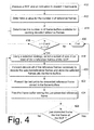
- Fig. 4 shows a methodological implementation of the exemplary reverse presenter for reverse playback that does selective decoding and caching of reference frames. This methodological implementation may be performed in software, hardware, or a combination thereof.
- the exemplary reverse presenter determines a value for the number n of reference frames, where n represents the actual number of reference frames in the BOF or an upper bound of reference frames. To determine this, the exemplary reverse presenter may cache and parse the compressed form of the BOF to identify and count reference frames. Alternatively, it may use a time interval and BOF structure limits to estimate a maximum number of reference frames.
- the exemplary reverse presenter determines a value of m , where m represents the number of frame-buffers available for temporarily storing decoded reference frames. It may do this by memory tracking techniques that track specific number of frame-buffers and memory locations available in a memory system. It may also receive this information from such a memory tracking system.
- the exemplary reverse presenter selects a subset of size m (or less) of the n reference frames of the BOF. If any reference frame has already been presented, then that frame is not included in the subset. Typically, this selection includes at least the I -frame and the last yet-to-be-presented P -frame (where "last" is viewed in a forward direction of the BOF). When there are more than two frame-buffers, then m - 2 more of the P -frame (that are between the I -frame and the first yet-to-be-presented P -frame) are also selected.
- One strategy may be to use a binary subdivision to select from the remaining reference frames.
- the exemplary reverse presenter may be configured to employ one of the two selection strategies described below in sub-sections titled "Frame-buffer Selection Strategies For Small n", “Frame-buffers Selection Strategy For Medium n “ and “Frame-buffers Selection Strategy For Large n”.
- the exemplary reverse presenter forward-decodes all of the reference frames necessary to decode all of the selected reference frames. If a frame needed to decode a selected reference frame is already stored, then there is no need to decode it. In other words, it does nothing to a selected reference frame if it is already decoded and stored in the frame-buffers.
- each decoded reference frame of the BOF preceding the last yet-to-be-presented reference frame is temporarily stored. If a decoded frame is not one of the selected frames, then it will be discarded and its frame-buffer is free to store one of the selected reference frames.
- the frame-buffers store the selected reference frames.
- the last yet-to-be-presented reference frame (e.g., I -/ P -frame) stored in the frame-buffers. Since this is a reverse playback of the BOF, presenting the last yet-to-be-presented reference frame produces a reverse presentation of the reference frames of the BOF.
- the exemplary reverse presenter may also be presenting any intervening non-reference frames (e.g., B -frames) in reverse as well.
- any intervening non-reference frames e.g., B -frames
- the exemplary reverse presenter frees the frame-buffer in which the just-presented reference frame is stored. Since the just-presented reference frame is no longer needed for presentation or for further decoding of any other frame, the memory holding it can be freed for other uses.
- the selection of a threshold that divides a "small” n from a “medium” n from a “large” n is not entirely arbitrary, the selection of the threshold typically includes a degree of heuristics. It is largely dependent upon the computational capacity of the actual implementation of the exemplary reverse presenter. For example, the threshold between "small” and “medium” may be on the order of about eight while the threshold between "medium” and “large” may be on the order of about 500-1000. However, one may utilize the concepts described here to adjust that threshold to meet the specific implementation needs.
- This strategy may be employed in and around the function described above in block 318 of Fig. 3. These tables were generated by the output of the optimal small n algorithm.
- the exemplary reverse presenter starts generating at the first frame (e.g., I 1 ) and recursively generates the last to-be-presented frame. It may discard the I frame in favor of caching a later P frame to reduce the length of the first run.
- n I 1 P 2 P 3 P 4 P 5 P 6 P 7 P 8 P 9 Total 3 2 1 1 n/a n/a n/a n/a n/a n/a 4 4 2 2 1 1 n/a n/a n/a n/a 6 5 2 2 1 2 1 n/a n/a n/a n/a 8 6 3 2 2 1 2 1 n/a n/a 11 7 3 3 2 2 1 2 1 n/a n/a 14 8 3 3 2 3 2 1 2 1 n/a 17 9 3 3 3 3 3 2 1 2 2 1 20
- a new last to-be-presented frame is selected and a new reference frame between the first frame and the new last to-be-presented frame is stored in a frame-buffer.
- This strategy selects frames with the goal of minimizing the size of the one or more span of frames that must be decoded (or re-decoded). In doing so, the overall operation of decoding (and re-decoding as necessary) of the remaining yet-to-be-presented frames is recursively divided into two sub-operations. Each sub-operation may have fewer frame-buffers and may be solved using the smaller cases of n with fewer available frame-buffers m .
- the selection strategy of the exemplary reverse presenter may dramatically reduce the amount of re-decoding while also eliminating the need for large amounts of buffering (which is required of the conventional approaches).
- this frame-buffer selection strategy of the exemplary reverse presenter for a medium number (n) of reference frames utilizes the strategy described below.
- This strategy may be employed in and around the function described above in block 318 of Fig. 3.
- This selection strategy may also be called the "memoization” strategy.
- “memoization” is an algorithmic technique that saves (i.e., memoizes) a computed result for later reuse, rather than recomputing the result again under the same conditions.
- a span is the frames between selected frames (for caching).
- a span length is based upon how many frames are in a span. This selection strategy continues to divide spans into still smaller spans until a known combination of a span matches a known combination of frames and buffers.
- This frame-buffer selection strategy of the exemplary reverse presenter defines, for decoding and displaying n frames in reverse order using m buffers, the 'first frame to retain' F(m, n). This is the first frame that, after decoding, does not have its buffer immediately freed. The buffer this frame is decoded into will not be freed until the frame has actually been displayed. Arbitrarily, the number of the first frame is chosen to be 1.
- the number of decodes required assuming the first frame to retain is x breaks down as: Decode frames up to and including frame x x Number of decodes to decode and display frames after x D(m - 1, n - x) Display frame x 0 Decode and display frames up to x - 1 D(m, x - 1)
- this frame-buffer selection strategy of the exemplary reverse presenter for a large number ( n ) of reference frames, where n greater than about 8 and m ⁇ n , utilizes the strategy described below.
- This strategy may be employed in and around the function described above in block 318 of Fig. 3.
- This selection strategy may also be called the "normalized arithmetic span-width sequence" strategy. It focuses on span length.
- a span is the frames between selected frames (for caching).
- a span length is based upon how many frames are in a span. This selection strategy attempts to minimize the length of multiple re-decodes of the longest of the multiple spans.
- the number of times a frame-buffer is re-decoded is proportional to the length of the span between selected frames ⁇ which are cached in the frame-buffers. As cached frames are displayed, their frame-buffers are no longer required and may be reused to cache re-decoded frames.
- the permutational optimizations of the selection strategy are not as significant as the relative number of frames to decode.
- the selection strategy endeavors to minimize the span lengths of each "re-decode" block while accounting for the increasing number of frame-buffers as the BOF is decoded.
- the span lengths are proportional to 1, 2, 3, 4, 5, ... m- 2 (i.e. in frame index order the relative span widths would be m-2, m-1, ..., 3, 2, 1).
- At least one frame-buffer is required for the first frame, the n th frame and one adjacent to the n th frame (i.e. at n-1) to decode the last interval.
- a buffer frees up to decode the next last interval.
- frames 1 to 100 would first be decoded once (to generate the cache points) then the spacing between re-decoded frames would only be 2 frames. This produces a maximum re-decode count for a given frame of at most 3. For example, to decode 91..96 there is two free frames (from 99 & 100), so 94 and 95 would be cached (re-decode 92, 93, 94, 95). Then 2 frames would be available to decode 91 and 93 (from 95 & 96 freeing up). Similarly for 1..21 there would be 8 frames available (applying the same arithmetic spacing algorithm, the frames would be a re-decoding cost of 2).
- This selection strategy progressively increases the length of each span (relative to the last frame).
- a binary subdivision algorithm would select frames 1, 50, 75, 87, 93, 96, 99 and 104. On average, each frame would be decoded In(g) times, for a total of approximately 700 decoding cost.
- Our first algorithm uses the extra buffers to reduce the first span to a length of 21 instead of 50.
- a BOF contains B-frames the schemes described above, involving using fewer buffers than there are non-reference frames in a BOF, require an extra buffer to be used. This buffer is used to save the last-decoded reference frame until the non-reference frames that reference it are displayed.
- Algorithms specifically designed to minimize the maximum number of decodes, or the maximum time for decodes can also be designed.
- each BOF has a single key-frame (e.g., an I -frame) and starts with such. It also assumes that the key-frame is followed by other reference frames (e.g., P -frames) and/or non-reference frames (e.g., B -frames).
- key-frame e.g., an I -frame
- other reference frames e.g., P -frames
- non-reference frames e.g., B -frames
- BOF structures that exist. These structures have multiple key-frames (e.g., an I -frames), These may be decomposed into sub-BOF groups with each having one key-frame when playing in reverse.
- the VOBUs of DVD may be viewed as a large BOF composed of many sub-BOF groups.
- a BOF may be decomposed into multiple sub-BOF groups with each having a single I -frame and each sub-BOF group being formed by the span of frames from one I -frame to the next I -frame.
- the exemplary reverse presenter performs a block level reverse presentation of the sub-BOF groups, Consequently, the decoding of the frames of each sub-BOF is reversed.
- the first frame from each sub-BOF group may be cached for the next sub-BOF group to decode.
- BOF 1 I 1 B 2 F 3 P 4 B 5 B 6 I 7 B 8 B 9 P 10 B 11 I 12 B 13 I 14 .
- the frame I 12 may be kept around when generating the B 11 frame while displaying BOF 2 .
- this function may be performed during block 310 of Fig. 3 or block 410 of Fig. 4.
- the received BOF is decomposed into multiple sub-BOF groups. The remainder of each process is operated on the sub-BOFs and when completed they return to the beginning to operate on the next sub-BOFs.
- B -frames are exclusively non-reference frames.
- other more complex formats exist ⁇ such as the H.264 standard. These formats have more complex BOF structures, such as BOFs with hierarchical reference frames.
- B -frames may serve as reference frames for other B -frames.
- BOF 500 of Fig. 5 For example, suppose the following BOF structure exists for the sequence I 1 B 2 B 3 B 4 B 5 B 6 I 7 B 8 B 9 B 10 B 11 B 12 I 13 B 14 I 15 , as illustrated by BOF 500 of Fig. 5.
- the BOF 500 includes reference frames 510 and non-reference frames 520.
- Some of these reference frames (in particular, B 2 B 4 B 6 B 8 B 11 B 14 ) are B -frames and would typically only be non-reference frames.
- these B -frames are reference frames because other frames (in particular, B 3 B 5 B 9 B 10 B 12 B 14 ) depend upon them. It may be decomposed into three sub-BOFs, 530, 532, and 534.
- the exemplary reverse presenter performs block reversal decomposition (described above) may be applied to each interval (e.g., each sub-BOF) between reference frames.
- each interval e.g., each sub-BOF
- sub-BOF 3 (534) of Fig. 5 may be reversed and presented.
- Frame I 13 may be cached and used to reverse and play sub-BOF 2 (532).
- frame I 7 may be cached and used to reverse and play sub-BOF 1 (530).
- Block reversals may also be applied to sub-BOFs between pseudo-reference frames 515.
- the sub-BOF 530 of B 2 .. B 6 may be decomposed into two sub-sub-BOFs consisting of B 4 .. B 6 and B 2 .. B 4 , respectfully.
- Each sub-sub-BOF may be independently reversed.
- the exemplary reverse presenter may decompose the BOF in another way, such as when it knows the number of reference frames between "interval reference frames".
- the interval reference frames are the I -frames bounding each space, such as I 1 , I 7 , I 13 and I 15 in Fig. 5).
- the sub-BOF 1 (530) interval has five reference and pseudo-reference frames ( I 1 B 2 B 4 B 6 I 7 ) and two non-reference frames ( B 3 B 5 ).
- the exemplary reverse presenter may assign the key-frame caching locations. This distributes a larger number of frame-buffers to branches containing a larger number of frames which need to be re-decoded.
- a frame is generated is completely generated from other frames.
- a B frame can be reconstructed from the two adjacent keyframes.
- other more complex formats exist ⁇ such as H.264, where a frame can be subdivided into smaller regions.
- a frame can be split into slices (16 pixel high stripes), slices can be divided into macroblocks (16x16 pixel blocks) and macroblocks can be divided into sub-macroblocks (quarters or halves of macroblocks) and so on.
- a non-reference frame is still defined as a frame which is not used to generate other frames, whereas a frame is a reference frame if it is still required to generate another frame.
- the exemplary reverse presenter creates a directed acyclic dependency graph similar to that shown in Fig. 5.
- Fig. 6 shows a methodological implementation of the exemplary reverse presenter performed by the media stream rendering system 200 (or some portion thereof). This methodological implementation may be performed in software, hardware, or a combination thereof.
- the exemplary reverse presenter performs block reversal decomposition on each interval.
- the exemplary reverse presenter performs block reversal decomposition on each sub-interval.
- an implementation of the techniques described herein may calculate the relative costs of decoding of I -frames and P -frames.
- the environment 700 includes one or more multimedia content providers 702, a content distribution system 706, and one or more presentation devices 708(1), 708(2), ..., 708(N) coupled to the content distribution system 706 via a broadcast network 710.
- Multimedia content provider 702 includes a content server 712 and stored content 714, such as movies, television programs, commercials, music, and similar audio and/or video content.
- Content server 712 controls distribution of the stored content 714 from content provider 702 to the content distribution system 706. Additionally, content server 702 controls distribution of live content (e.g., content that was not previously stored, such as live feeds) and/or content stored at other locations to the content distribution system 706.
- live content e.g., content that was not previously stored, such as live feeds
- Content distribution system 706 is representative of a headend service that provides multimedia content to multiple subscribers.
- Broadcast network 710 can include a cable television network, RF, microwave, satellite, and/or data network, such as the Internet, and may also include wired or wireless media using any broadcast format or broadcast protocol. Additionally, broadcast network 710 may be any type of network, using any type of network topology and any network communication protocol, and may be represented or otherwise implemented as a combination of two or more networks,
- Presentation device 708(2) is also coupled to receive broadcast content from broadcast network 710 and provide the received content to associated television 736(2).
- Presentation device 708(N) is an example of a combination television 738 and integrated set-top box 740.
- the set-top box incorporated into the television may receive broadcast signals via a satellite dish (similar to satellite dish 734) and/or via broadcast network 710.
- presentation devices 706 may receive broadcast signals via the Internet or any other broadcast medium.
- this exemplary environment 700 has been described in terms of a digital video broadcast (DVB) environment. Indeed, that is an exemplary environment. However, the exemplary reverse presenter may be implemented without the whole of the DVB environment itself. Instead, it may be implemented by a stand-alone presentation device, such as illustrated by device 708(X).
- DVD digital video broadcast
- Stand-alone presentation device 748(X) accesses digital video from a storage medium 744, such as a DVD disk. It provides the content from the medium to an associated television 739. Examples of such a stand-alone presentation device include a DVD player, a personal video recorder, etc.
- Fig. 8 illustrates an exemplary implementation 800 of a presentation device 708 shown as a stand-alone unit that connects to a television 736.
- Presentation device 708 may be implemented in any number of embodiments, including as a set-top box, a satellite receiver, a TV recorder with a hard disk, a game console, an information appliance, a DVD player, a personal video recorder, and so forth.
- Presentation device 708 includes a wireless receiving port 802, such as an infrared (IR) or Bluetooth wireless port, for receiving wireless communications from a remote control device 804, a handheld input device 806, or any other wireless device, such as a wireless keyboard.
- Handheld input device 806 may be a personal digital assistant (PDA), handheld computer, wireless phone, or the like.
- PDA personal digital assistant
- a wired keyboard 808 is coupled to communicate with the presentation device 708.
- remote control device 804, handheld device 806, and/or keyboard 808 may use an RF communication link or other mode of transmission to communicate with presentation device 708.
- Presentation device 708 may have a storage medium reader 809 for reading content storage media, such as DVD disks.
- a stand-alone or non-stand-alone presentation device 708 may include the storage medium reader 809.
- Presentation device 708 may receive one or more broadcast signals 810 from one or more broadcast sources, such as from a satellite or from a broadcast network.
- Presentation device 708 includes hardware and/or software for receiving and decoding broadcast signal 810, such as an NTSC, PAL, SECAM or other TV system video signal.
- Presentation device 708 also includes hardware and/or software for providing the user with a graphical user interface by which the user can, for example, access various network services, configure the presentation device 708, and perform other functions.
- Presentation device 708 may be capable of communicating with other devices via one or more connections including a conventional telephone link 812, an ISDN link 814, a cable link 816, an Ethernet link 818, a DSL link 820, and the like. Presentation device 708 may use any one or more of the various communication links 812-820 at a particular instant to communicate with any number of other devices.
- Presentation device 708 generates video signal(s) 820 and audio signal(s) 822, both of which are communicated to television 736.
- the video signals and audio signals may be communicated from presentation device 708 to television 736 via an RF (radio frequency) link, S-video link, composite video link, component video link, or other communication link.
- RF radio frequency
- the presentation device 708 may include one or more lights or other indicators identifying the current status of the device. Additionally, the presentation device may include one or more control buttons, switches, or other selectable controls for controlling operation of the device.
- Fig. 9 illustrates selected components of presentation device 708 shown in Figs. 7 and 8.
- Presentation device 708 includes a first tuner 900 and an optional second tuner 902. These tuners may be called the receiving unit.
- the tuners 900 and 902 are representative of one or more in-band tuners that tune to various frequencies or channels to receive television signals, as well as an out-of-band tuner that tunes to the broadcast channel over which other content may be broadcast to presentation device 708.
- Presentation device 708 also includes one or more processors 304 and one or more memory components.
- memory components include a random access memory (RAM) 906, a disk drive 908, a mass storage component 910, and a non-volatile memory 912 (e.g., ROM, Flash, EPROM, EEPROM, etc.).
- RAM random access memory
- disk drive 908 a disk drive 908
- mass storage component 910 a non-volatile memory 912 (e.g., ROM, Flash, EPROM, EEPROM, etc.).
- non-volatile memory 912 e.g., ROM, Flash, EPROM, EEPROM, etc.
- presentation device 708 can include a range of processing and memory capabilities, and may include more or fewer types of memory components than those illustrated in Fig. 9.
- Processor(s) 904 process various instructions to control the operation of presentation device 708 and to communicate with other electronic and computing devices.
- the memory components e.g., RAM 906, disk drive 908, storage media 910, and non-volatile memory 912 store various information and/or data such as multimedia content, electronic program data, web content data, configuration information for presentation device 708, and/or graphical user interface information.
- the device may cache data into any one of these many memory components.
- An operating system 914 and one or more application programs 916 may be stored in non-volatile memory 912 and executed on processor 904 to provide a runtime environment.
- a runtime environment facilitates extensibility of presentation device 708 by allowing various interfaces to be defined that, in turn, allow application programs 916 to interact with presentation device 708.
- the application programs 916 that may be implemented at presentation device 708 can include an electronic program guide (EPG), an email program to facilitate electronic mail, and so on.
- EPG electronic program guide
- email program to facilitate electronic mail
- Presentation device 708 can also include other components pertaining to a television entertainment system which are not illustrated in this example for simplicity purposes.
- presentation device 708 can include a user interface application and user interface lights, buttons, controls, etc. to facilitate viewer interaction with the device.
- Presentation device 708 also includes a decoder 920 to decode a broadcast video signal, such as an NTSC, PAL, SECAM or other TV system video signal. It may also be a decoder for decoding a digital compressed video stream, such as one formed as MPEG. This may be same type of decoder as the decoders 210, 212, and 214 of Fig. 2.
- Presentation device 708 further includes a wireless interface 922, a network interface 924, a serial and/or parallel interface 926, and a modem 928.
- Wireless interface 922 allows presentation device 708 to receive input commands and other information from a user-operated input device, such as from a remote control device or from another IR, Bluetooth, or similar RF input device.
- Network interface 924 and serial and/or parallel interface 926 allow presentation device 708 to interact and communicate with other electronic and computing devices via various communication links. Although not shown, presentation device 708 may also include other types of data communication interfaces to communicate with other devices. Modem 928 facilitates presentation device 708 communication with other electronic and computing devices via a conventional telephone line.
- Presentation device 708 also includes an audio/video output 930 that provides signals to a television or other device that processes and/or presents or otherwise renders the audio and video data. This output may be called the display.
- presentation device 708 may be implemented in an application specific integrated circuit (ASIC). Additionally, a system bus (not shown) typically connects the various components within presentation device 708.
- ASIC application specific integrated circuit
- Fig. 10 illustrates an example of a suitable computing environment 1000 within which an exemplary reverse presenter, as described herein, may be implemented (either fully or partially).
- the computing environment 1000 may be utilized in the computer and network architectures described herein.
- the exemplary reverse presenter may be implemented with numerous other general purpose or special purpose computing system environments or configurations.
- Examples of well known computing systems, environments, and/or configurations that may be suitable for use include, but are not limited to, personal computers, server computers, thin clients, thick clients, hand-held or laptop devices, multiprocessor systems, microprocessor-based systems, set top boxes, programmable consumer electronics, network PCs, minicomputers, mainframe computers, distributed computing environments that include any of the above systems or devices, and the like.
- the exemplary reverse presenter may be described in the general context of computer-executable instructions, such as program modules, being executed by a computer.
- program modules include routines, programs, objects, components, data structures, etc. that perform particular tasks or implement particular abstract data types.
- the exemplary reverse presenter may also be practiced in distributed computing environments where tasks are performed by remote processing devices that are linked through a communications network.
- program modules may be located in both local and remote computer storage media including memory storage devices.
- the computing environment 1000 includes a general-purpose computing device in the form of a computer 1002, which may be another example of the presentation device 708.
- the components of computer 1002 may include, by are not limited to, one or more processors or processing units 1004, a system memory 1006, and a system bus 1008 that couples various system components including the processor 1004 to the system memory 1006.
- the system bus 1008 represents one or more of any of several types of bus structures, using any of a variety of bus architectures, including a memory bus or memory controller, a peripheral bus, an accelerated graphics port, or a local bus using any of a variety of bus architectures.
- bus architectures can include a CardBus, Personal Computer Memory Card International Association (PCMCIA), Accelerated Graphics Port (AGP), Small Computer System Interface (SCSI), Universal Serial Bus (USB), IEEE 1394, a Video Electronics Standards Association (VESA) local bus, and a Peripheral Component Interconnects (PCI) bus also known as a Mezzanine bus.
- PCMCIA Personal Computer Memory Card International Association
- AGP Accelerated Graphics Port
- SCSI Small Computer System Interface
- USB Universal Serial Bus
- IEEE 1394 IEEE 1394
- VESA Video Electronics Standards Association
- PCI Peripheral Component Interconnects
- the hard disk drive 1016, magnetic disk drive 1018, and optical disk drive 1022 are each connected to the system bus 1008 by one or more data media interfaces 1026.
- the hard disk drive 1016, magnetic disk drive 1018, and optical disk drive 1022 may be connected to the system bus 1008 by one or more interfaces (not shown).
- the disk drives and their associated computer-readable media provide non-volatile storage of computer readable instructions, data structures, program modules, and other data for computer 1002.
- a hard disk 1016 a removable magnetic disk 1020, and a removable optical disk 1024
- other types of computer readable media which may store data that is accessible by a computer, such as magnetic cassettes or other magnetic storage devices, flash memory cards, CD-ROM, digital versatile disks (DVD) or other optical storage, random access memories (RAM), read only memories (ROM), electrically erasable programmable read-only memory (EEPROM), and the like, may also be utilized to implement the exemplary computing system and environment.
- Any number of program modules may be stored on the hard disk 1016, magnetic disk 1020, optical disk 1024, ROM 1012, and/or RAM 1010, including, by way of example, an operating system 1026, one or more application programs 1028, other program modules 1030, and program data 1032.
- a user may enter commands and information into computer 1002 via input devices, such as a keyboard 1034 and a pointing device 1036 (e.g., a "mouse").
- Other input devices 1038 may include a microphone, joystick, game pad, satellite dish, serial port, scanner, and/or the like.
- input/output interfaces 1040 that are coupled to the system bus 1008, but may be connected by other interface and bus structures, such as a parallel port, game port, or a universal serial bus (USB).
- a monitor 1042 or other type of display device may also be connected to the system bus 1008 via an interface, such as a video adapter 1044.
- other output peripheral devices may include components, such as speakers (not shown) and a printer 1046, which may be connected to computer 1002 via the input/output interfaces 1040.
- Computer 1002 may operate in a networked environment using logical connections to one or more remote computers, such as a remote computing device 1048.
- the remote computing device 1048 may be a personal computer, portable computer, a server, a router, a network computer, a peer device or other common network node, and the like.
- the remote computing device 1048 is illustrated as a portable computer that may include many or all of the elements and features described herein relative to computer 1002.
- Logical connections between computer 1002 and the remote computer 1048 are depicted as a local area network (LAN) 1050 and a general wide area network (WAN) 1052.
- LAN local area network
- WAN wide area network
- the computer 1002 When implemented in a LAN networking environment, the computer 1002 is connected to a local network 1050 via a network interface or adapter 1054. When implemented in a WAN networking environment, the computer 1002 typically includes a modem 1456 or other means for establishing communications over the wide network 1052.
- the modem 1056 which may be internal or external to computer 1002, may be connected to the system bus 1008 via the input/output interfaces 1040 or other appropriate mechanisms. It is to be appreciated that the illustrated network connections are exemplary and that other means of establishing communication link(s) between the computers 1002 and 1048 may be employed.
- An implementation of an exemplary reverse presenter may be described in the general context of computer-executable instructions, such as program modules, executed by one or more computers or other devices.
- program modules include routines, programs, objects, components, data structures, etc. that perform particular tasks or implement particular abstract data types.
- functionality of the program modules may be combined or distributed as desired in various embodiments.
- Computer readable media may be any available media that may be accessed by a computer.
- Computer readable media may comprise "computer storage media” and "communications media.”
- Communication media typically embodies computer readable instructions, data structures, program modules, or other data in a modulated data signal, such as carrier wave or other transport mechanism. Communication media also includes any information delivery media.
- modulated data signal means a signal that has one or more of its characteristics set or changed in such a manner as to encode information in the signal.
- communication media includes wired media, such as a wired network or direct-wired connection, and wireless media, such as acoustic, RF, infrared, and other wireless media. Combinations of any of the above are also included within the scope of computer readable media.
Landscapes
- Engineering & Computer Science (AREA)
- Signal Processing (AREA)
- Multimedia (AREA)
- Compression Or Coding Systems Of Tv Signals (AREA)
- Television Signal Processing For Recording (AREA)
- Signal Processing For Digital Recording And Reproducing (AREA)
Abstract
Described herein is an implementation that facilitates the reverse presentation of an encoded digital media stream. This abstract itself is not intended to limit the scope of this patent. The scope of the present invention is pointed out in the appending claims. <IMAGE>
Description
This invention generally relates to a digital multimedia technology.
As processing and storage technologies continue to improve, many personal
computing systems (e.g., personal computers, set-top boxes, etc.) now have the
capacity to receive, process and render multimedia objects. Such objects have
multimedia content that includes a combination of audio, graphical, and/or video
content. The multimedia content may be delivered to the computing system in any
of a number of ways including, for example, on a compact disk read-only memory
(CD-ROM), on a digital versatile disk read-only memory (DVD-ROM), via a
communicatively coupled data network (e.g., Internet), and the like.
Due to the amount of data required to accurately represent such multimedia
content, it is typically delivered to the computing system in an encoded,
compressed form. To reproduce the original content for presentation, the
multimedia content must be decompressed and decoded before it is presented.
Here, presenting includes communicating the multimedia content to a display
and/or audio device.
A number of multimedia standards have been developed that define the
format and meaning of encoded multimedia content for purposes of distribution.
Organizations such as the Moving Picture Experts Group (MPEG) under the
auspices of the International Standards Organization (ISO) and International
Electrotechnical Commission (IEC), and the Video Coding Experts Group
(VCEG) under the auspices of the International Telecommunications Union (ITU),
have developed a number of multimedia coding standards (e.g., MPEG-1, MPEG-2,
MPEG-4, H.261, H.263, and the like).
Simplistically speaking, the encoding process removes spatial and temporal
redundancies from the media content, thereby reducing the amount of data needed
to represent the media content and, as a result, reducing the bandwidth burden to
store and/or transmit such media content. Examples of the encoding process
include entropy decoding, motion compensated prediction, inverse quantization,
inverse transformation, and addition of the inverse transformed results to the
prediction.
Conversely, the decoding process is, simplistically speaking, typically the
inverse of the encoding process.
Rendering typically includes an additional step of digital to analog
conversion (with filtering). That generates an approximate representation of the
original analog media signal.
Herein, a "media stream" is a multimedia object (containing audio and/or
visual content) that is compressed and encoded in accordance with generally
available mechanisms for doing so. Furthermore, such a media stream is intended
to be decoded and rendered in accordance with generally available mechanisms
for doing so.
Without a loss of generality, the same techniques can be applied to any
media stream that has a similar structure which reduces temporal or spatial
redundancies. For example, many audio compression formats have keyframes
followed by modification data to regenerate an approximation of the original
uncompressed stream.
There are many different video-stream data formats. For example: H.263,
MPEG-1, MPEG-2, MPEG-4 Visual, H.264/AVC, and DV formats.
There are many different audio-stream data formats. For example: DTS
audio or MLP audio.
The predominant digital video compression and transmission formats are
from a family called block-based motion-compensated hybrid video coders, as
typified by the ISO/IEC MPEG-X (Moving Picture Experts Group) and ITU-T
VCEG H.26X (Video Coding Experts Group) standards. This family of standards
is used for coding audio-visual information (e.g., movies, video, music, and such)
in a digital compressed format.
For the convenience of explanation, the MPEG-2 video stream (also known
as an H.262 video stream) is generally discussed and described herein, as it has a
structure that is typical of conventional video coding approaches. However, those
who are skilled in the art understand and appreciate that other such digital video
compression and transmission formats exist and may be used.
The MPEG-2 format may be referred to as a generally "forward decoding"
format. An example representation of a MPEG format is shown in Fig. 1 generally
at 10. Each video sequence is composed of a sequence of frames that is typically
called Groups of Pictures (or "GOPs"). A GOP is composed of a sequence of
pictures or frames. The GOP data is compressed as a sequence of I-, P- and B-frames
where:
- An I-frame (i.e., intra-frame) is an independent starting image - (compressed in a similar format to a JPEG image). An I-frame or "key frame" (such as I-frame 12) is encoded as a single image, with no reference to any past or future frames. An I-frame is considered a "reference frame" in MPEG-2, as its content can be used in the decoding process for one subsequent P-frame or multiple subsequent B-frames in decoding order.
- A P-frame (i.e., forward predicted frame) is computed by moving around rectangles (called macroblocks) from the previous I- or P-frame then (if so indicated by the encoder) applying a 'correction' called a residual. Subsequent P-frames (such as P-frame 18) is encoded relative to the past reference frame (such as a previous I- or P-frame). P-frames can also be considered as "delta frames" in that they contain changes relative to their reference frame. A P-frame is also considered a "reference frame" in MPEG-2, as its content can be used in the decoding process for one subsequent P-frame or multiple subsequent B-frames in decoding order.
- Zero or more B-frames (i.e., bi-directional predicted frames, such as frames 14 and 16) are formed by a combination of rectangles from the adjacent I- or P-frames, followed (if so indicated by the encoder) by a correction factor. Several B-frames may lie between a pair of reference frames (frames that are either I- or P-frames). In MPEG-2, B-frames are not called reference frames, as they are not used as references for the decoding of subsequent frames in decoding order.
The GOP structure is intended to assist random access into the stream. A
GOP is typically an independently decodable unit that may be of any size as long
as it begins with an I-frame.
One problem associated with the MPEG-2 format pertains to being able to
play back the data in the reverse of the ordinary display order. Playing the data
forward is typically not a problem because the format itself is forward decoding-meaning
that one must typically decode the I-frame first and then move on to the
other frames in the GOP. Playing back the data in reverse, however, is more
challenging because the GOPs inherently resist a straightforward backward-decoding.
Similar challenges exist to audio data which are compressed as a starting
vector of values (i.e. one per audio channel) followed by delta frames.
Normally, when images are recorded on a disk, such as a DVD, the content
is actually broken into small units covering a pre-determined time period
(typically approximately ½-second units or video object basic units ("VOBUs")).
The advantage of this format is that when you play the video, you can progress
through the video units one by one. If one wants to jump to an arbitrary piece of
video, one can simply jump to the video unit of interest and the audio and video
will be synchronized. The location at which all streams are synchronized is
referred to as a "clean point". Accordingly, when the video and audio units are
compressed, they are compressed in a unit that is to be rendered at the exact same
time―that is, there is no skew between the audio and video.
All references to I-frames, when discussed within the MPEG-2 context
may be extended to key-frames in other data formats. The term I-frame is
synonymous with a key-frame when discussed outside of the MPEG-2 context.
Fig. 2 illustrates an exemplary system 200 that can render data from a
media stream source, such as a DVD. System 200 includes an application 202 that
communicates with a source component 204 that reads data off of a DVD 206.
The data that is read off of the DVD includes audio and video data that has been
encoded and multiplexed together.
As the source reads the data off of the DVD, it retrieves timestamps from
the data packets, which are then used to synchronize and schedule the packets for
rendering. The packets are then provided to a demultiplexer (or "demux") 208
which splits the packets into different constituent portions―audio, video and, if
present, subpicture packets.
The packets are then provided by the demultiplexer to an associated
decoder, such as video decoder 214 (for decoding video packets), audio decoder
212 (for decoding audio packets) and subpicture decoder 214 (for decoding
subpicture packets). Each one of the packets has associated timing information,
which defines when the contents of the packet are supposed to be rendered. These
packets may be a GOP (as described above with regard to MPEG).
The decoders then decompress their associated packets and send the
individual data samples or packets (including the packets' timestamps) to the
appropriate renderers, such as video renderer 216 and audio renderer 218. Each of
these decoders typically has a cache for temporarily storing decoded packets (or
portions thereof). Typically, a cache is at least large enough to accommodate
frame decoding that reference data from other frames.
System 200 also typically includes a global clock 220 that is used by the
various renderers to ascertain when to render certain data samples whose
timestamps coincide with a time indicated by the global clock.
Assume now that a user indicates, via application 202, that she wishes to
view the content in reverse order. This may be called "reverse playback,"
"backwards play", "rewind," "backwards scan," "reverse trick play," or "reverse
scan."
The frames of a GOP are designed to be decoded and presented in generally
the same direction, which will be called the "forward" direction herein. That is the
same direction in which the frames of the GOP are encoded. However, the actual
specific order that the frames of a GOP are encoded typically differs from the
actual specific order of their presentation.
To decode a B-frame (such as frames 14 and 16 of Fig. 1), the previous I-/P-frame
and the next I-/P-frame must already be present. For example, a GOP
may be presented in this order I1B2B3P4B5P6, but it would be encoded in the order
I1P4B2B3P6B5. Note that P4 must be decoded before B2 and B3 may be generated.
P4 must be decoded in order to generate P6.
Consequently, simply reversing the decoding order is insufficient to
produce reverse playback of the GOP. In the above example, the P6 depends on
the previous P4 frame, which hasn't yet been decoded, if decoding occurs
backwards. Furthermore, the P4 depends on the previous I1 frame, which also
hasn't yet been decoded, if decoding occurs backwards. Further still, the B
frames depend on one or more frames that haven't been decoded yet when
decoding in reverse.
In light of this, one conventional approach to the "reverse playback" of a
GOP involves a reverse presentation of the frames in the GOP so that before each
frame presentation, all of the frames (or at least all of the reference frames) that
proceed the current frame are decoded. For example, for frames labeled ABCDE,
this conventional approach decodes frames ABCDE, and then displays frame E.
Next, it decodes frames ABCD, and then displays D. Next, it decodes ABC, and
then displays C, and so forth.
This conventional approach is highly time-consuming and it is very
inefficient since the system is decoding some of the same frames repeatedly. The
computations requirements are very high, but memory requirements are relatively
low.
Another conventional approach to the "reverse playback" of a GOP is to
decode forward as normal but temporarily store all of the decoded and now
uncompressed frames of the GOP. Once the entire GOP is decoded and stored, the
decoded frames are passed on to the renderers in reverse order. Therefore, stored
output frames are simply displayed in reverse order.
With this approach, the computations requirements are relatively low, but
memory requirements are relatively high. This conventional approach requires:
- A large amount of cache memory to cache the uncompressed images of the decoded frames of the GOP. Even for common formats such as DVD, or standard definition TV, 10MB or more of cache memory may be necessary. Higher HDTV resolutions typically require 50MB of memory.
- The cache memory is typically located in high-speed memory that is accessible to the decoder unit. The random rectangle extractions produce very cache-unfriendly accessing patterns. Typically, this memory will need to be in the typically expensive and limited local video memory (VRAM) on a video card.
- Since the GOPs typically need to be pipelined using at least double caching to ensure a constant output speed, the memory requirements of the cache memory are typically doubled. While the overall decoding speed for a block in reverse is the same as one played forwards at the same speed, the decoder will need to almost instantly decode the block, and then play it in reverse at normal speed. By having a fully decoded GOP in memory, the decoder unit has a GOP worth of presentation time to decode the next GOP.
Furthermore, post-processing of the content (such as de-interlacing, scaling,
filtering, audio pitch correction, etc.) may require additional computational power
and temporary processing caches.
In recognition of the difficulties involved in reverse playback, some
conventional approaches simply decode and display only the key-frames (e.g., I-frames)
from each GOP. This produces a jerky slide-show-like reverse
presentation of still images appearing in the video stream. While straightforward,
this simplistic approach is ungraceful and utterly fails at simulating reverse motion
of the video content of the video stream.
An implementation is described herein that facilitates the reverse
presentation of an encoded digital media streams.
This summary itself is not intended to limit the scope of this patent.
Moreover, the title of this patent is not intended to limit the scope of this patent.
For a better understanding of the present invention, please see the following
detailed description and appending claims, taken in conjunction with the
accompanying drawings. The scope of the present invention is pointed out in the
appending claims.
The same numbers are used throughout the drawings to reference like
elements and features.
Fig. 1 is a block diagram illustrating a group-of-pictures (GOP) that may be
used in accordance with an implementation described herein.
Fig. 2 is a block diagram of a system in accordance with an implementation
described herein.
Fig. 3 is a flow diagram showing a methodological implementation
described herein.
Fig. 4 is a flow diagram showing a methodological implementation
described herein.
Fig. 5 is a block diagram illustrating a complex group-of-pictures (GOP)
that may be used in accordance with an implementation described herein.
Fig. 6 is a flow diagram showing a methodological implementation
described herein.
Fig. 7 illustrates an exemplary environment in which an implementation
described herein may be employed.
Fig. 8 illustrates of an example presentation device, a television, and
various input devices that interact with the presentation device.
Fig. 9 is a block diagram that illustrates components of the example
presentation device(s) shown in Figs. 7 and 8.
Fig. 10 is an example of a computing operating environment capable of
(wholly or partially) implementing at least one embodiment described herein.
In the following description, for purposes of explanation, specific numbers,
materials and configurations are set forth in order to provide a thorough
understanding of the present invention. However, it will be apparent to one skilled
in the art that the present invention may be practiced without the specific
exemplary details. In other instances, well-known features are omitted or
simplified to clarify the description of the exemplary implementations of the
present invention, thereby better explaining the present invention. Furthermore, for
ease of understanding, certain method steps are delineated as separate steps;
however, these separately delineated steps should not be construed as necessarily
order dependent in their performance.
The following description sets forth one or more exemplary
implementations of a Reverse Presentation of Digital Media Streams that
incorporate elements recited in the appended claims. These implementations are
described with specificity in order to meet statutory written description,
enablement, and best-mode requirements. However, the description itself is not
intended to limit the scope of this patent.
The inventors intend these exemplary implementations to be examples. The
inventors do not intend these exemplary implementations to limit the scope of the
claimed present invention. Rather, the inventors have contemplated that the
claimed present invention might also be embodied and implemented in other ways,
in conjunction with other present or future technologies.
An example of an embodiment of a Reverse Presentation of Digital Media
Streams may be referred to as an "exemplary reverse presenter."
The one or more exemplary implementations, described herein, of the
present claimed invention may be implemented (in whole or in part) by the media
stream rendering system 200, a presentation device 708, and/or as part of a
computing environment like that shown in Fig. 10.
The exemplary reverse presenter facilitates the reverse playback of
compressed digital media streams. Most media stream formats are compressed
using independently decodable blocks containing a sequence of frames. For
convenience, such a block is called a block-of frames (BOF) herein. In MPEG, a
groups-of-pictures (GOP) is an example of such a BOF. Note that BOFs may
share frames (i.e. overlap) with adjacent BOFs in some situations (such as an open
GOP in MPEG2).
Herein, a "frame" refers to a compressed unit ofmedia data (typically audio
and/or visual data). The overall encoding process reduces temporal or spatial
redundancies within the media data of the frames of the BOF. When a frame is
decoded (or uncompressed), its media data is fully represented without any
compression (from temporal or spatial redundancy reduction).
Each BOF typically includes at least one key-frame (e.g., I-frame) or
reference vector that is followed by several delta frames. Similar procedures can
be used to decode various media streams such as audio which are compressed
using a similar structure.
The conventional approach to reverse playback of a stream is typically to
decode a BOF in a "forward" direction as normal but cache all of the decoded and
now uncompressed frames of the entire BOF. Once the entire BOF is decoded and
cached, the decoded frames are presented in reverse order.
This conventional and straightforward approach works for relatively small
uncompressed frame sizes and short BOF lengths. However, as the uncompressed
frame size increases, such as in the case of decoding HDTV images, the temporary
memory requirements may become prohibitive.
For interlaced 1920x1080 pixel images with ½ second long BOFs, over
300MB of memory are required to memorize the frames. Even worse, the cached
images must be located within the decoder's local memory (rather than on a main
memory). The memory bandwidth required to copy the decompressed images to a
main memory often exceeds the bandwidth of a system's internal buses.
Simply adding more local cache memory is economically
counterproductive since it only increases the component costs. At some point, this
brute-force solution (of adding more memory) will become cost prohibitive.
The exemplary reverse presenter facilitates improved reverse presentation
of a stream by performing more efficient reverse decoding of the BOFs of the
media stream. It also balances computational and memory requirements, so that
the content can still be reverse decoded if memory or computational resources are
limited.
The exemplary reverse presenter may be implemented (in whole or in part)
by the media stream rendering system 200 of Fig. 2, a presentation device 708 of
Figs. 7 and 9, and/or as part of a computing environment like that shown in Fig.
10.
The stream decoding function of the exemplary reverse presenter may
occur on a decoding unit with limited memory that accepts compressed
multimedia data of video and audio streams. The decoding unit comprises a
decoding controller (such as controller 940 of Fig. 9) and a hardware decoder
(such as decoders 210, 212, and 214 of Fig. 2 or decoder 930 of Fig. 6).
A decoder controller (such as controller 940 of Fig. 9) controls the
decoding process. It schedules frames to be decoded by the decoder. The decoder
controller may be performed in software, hardware, or a combination thereof. It
may be as a program module on the presentation device 708 and/or as part of a
computing environment like that shown in Fig. 10
A decoder (such as decoders 210, 212, and 214 of Fig. 2 or decoder 930 of
Fig. 6) is a dedicated decompression/decoding hardware, a software component
that performs the equivalent operation, or a combination of both. Since decoding is
typically handled by dedicated hardware, it is often possible to decode (or re-decode
frames) more rapidly than necessary for the frames to be displayed.
Herein, the term "frame-buffer" refers to a memory storage location
configured to store one uncompressed frame. Herein, a "cache" is a memory
storage. A cache may contain frame-buffers.
A "reference frame" is a type of frame having data that is used as a
reference to generate a frame dependent therefrom. A reference frame typically
must be decoded before its data may be referenced. A key-frame is always a
reference frame. However, intermediate frames, which are dependent on key-frames,
but also have one or more frames dependent therefrom, are also classified
as reference frames. In the MPEG realm, both I- and P-frames are categorized
as reference frames.
A "non-reference frame" is a type of frame containing no data referenced
by another frame. In addition to the data contained in a non-reference frame, the
generation of the fully decoded image in the frame depends upon the data of its
decoded reference frames. In the MPEG realm, B-frames are categorized as non-reference
frames since no frames depend upon them, but they depend upon two
reference frames (I- or P-frames). A non-reference frame is typically decoded
then discarded and does not need to be temporarily stored for the purpose of
decoding other frames.
The aspect of the exemplary reverse presenter, described below (with
regard to section titled, "Decoding Reference Frames, but Caching Encoded Non-Reference
Frames"), focuses on improved handling of non-reference frames (e.g.,
B-frames) relative to the reference frames (e.g., I-/P-frames). In doing so, it
provides an improved approach to reverse playback of a media stream.
Conversely, another aspect of the exemplary reverse presenter, described
below (with regard to section titled, "Decoding and Caching of Selective
Reference Frames"), focuses on improved handling of the reference frames (e.g.,
I-/P-frames) to produce an improved approach to reverse playback of a stream.
The improvement provided by this aspect is not based upon its handling of non-reference
frames (e.g., B-frames). However, both aspects of the exemplary
reverse presenter may be employed together. And, indeed, it may be desirable to
utilize both aspects concurrently to further improve the overall reverse playback
function.
This aspect of the exemplary reverse presenter achieves an improved
reverse playback of a BOF (such as a GOP) by forward decoding some or all of
the reference frames (e.g., I- or P-frames) of the BOF while caching the still-encoded
(thus still-compressed) non-reference frames (e.g., B-frames).
As the exemplary reverse presenter presents the frames of the BOF in
reverse order, it presents the already decoded reference frames, but before
presenting the non-reference frames, it decodes the still-encoded non-reference
frames in the cache based upon their already decoded reference frames.
I-frames are decoded independent of any previous or future frame
information. P-frames are a forward modification of a previous I- or P-frames.
Since B-frames only depend on the adjacent frames I-/P-frames, then B
frames may be decoded backwards by exchanging the frame indices of the
adjacent frames and decoding them forwards.
For example, suppose a resulting macroblock MB in the B-frame was a
function from a macroblock MP1 from the previous P-frame and a macroblock
MP2 from the next P-frame. If the B-frame is decoded forwards then: MB =
function 1 (MP1, MP2). However, when the indices of the B-frame are swapped, it
is now decoded like this: MB = function2(MP2 ,MP1), where function2 is
function1 with its operands exchanged.
Hence, the decoded macroblock of a B-frame may be generated by
reversing the decoding order of the adjacent frames and applying the same residual
correction.
The exemplary reverse presenter caches the compressed form of the non-reference
frames (e.g., B-frames). When the BOF-frames are being presented in
reverse order, cached compressed non-reference frames are then decoded. The
dependencies for decoding non-reference frames are resolved when the data of the
non-reference frames is needed for rendering, rather than well in advance.
The non-reference frames may be stored in a main system memory, a local
memory to improve access speed (such as VRAM), or in easily accessible system
memory to the decoder unit (such as AGP memory). Any of these may be
generically called a cache herein.
For example, if a typical BOF playback structure of
IBBPBBPBBPBBI (where the last I is shared by an adjecnt BOF) is used,
then the memory requirements for reverse playback may be about one-third of
what is required by the conventional approach of caching all decoded frames of a
BOF. In this example, the exemplary reverse presenter caches decoded versions
of only four of the ten frames, rather than all ten frames. In particular, it caches
decoded versions of the I- and P-frames.
The exemplary reverse presenter stores the compressed form of the six B-frames
in this example. Of the three types (I-, P-, and B-frames), the B-frames
represent the most compressed type of frame because they are dependent
upon two other frames. Avoiding the temporary storage of the decompressed data
of the B-frames represents a significant reduction in the memory requirements of
the traditional approach of caching all decoded frames of a BOF.
For this aspect of the exemplary reverse presenter, the specific BOF
structure is the typical BOF structure of IBBPBBPBBP. This is a common
BOF structure, but those of ordinary skill in the art understand and appreciate that
other BOF structures are possible and further understand and appreciate how this
aspect may be applied to those other possible structures.
Another way to retain (or effectively "cache") the non-reference frames in
compressed form is to simply leave them on whatever storage medium that the
video data arrived on. For example, the frames may be left on a DVD or hard
drive and their locations be read when desired.
Fig. 3 shows a methodological implementation of the exemplary reverse
presenter for reverse playback that includes decoding reference frames, but caches
encoded non-reference frames. This methodological implementation may be
performed in software, hardware, or a combination thereof.
At 310 of Fig. 3, the exemplary reverse presenter receives a BOF and an
indication that the received BOF is to be presented backwards (i.e., reverse
playback).
At 312, the exemplary reverse presenter forward decodes reference frames
of the received BOF.
At 314, the exemplary reverse presenter stores decoded reference frames of
the BOF and the still-encoded non-reference frames.
At 316, for each non-reference frame, it exchanges the frame indices of the
adjacent frames. Therefore, it reverses the dependencies for the non-reference
frames.
At 318 of Fig. 3, the exemplary reverse presenter presents the last reference
frame of the BOF that is yet-to-be-presented.
At 320, the exemplary reverse presenter generates the last non-reference
frame of the BOF that is yet-to-be-generated. The just-generated non-reference
frame is decoded based upon its dependencies to already-decoded reference
frames in the cache.
At 322, it presents the just-generated non-reference frame and optionally,
frees the frame-buffer storing the just-generated non-reference frame. Since the
just-generated non-reference frame is no longer needed for presentation or for
further decoding of any other frame, the memory holding it can be freed-up for
other uses. It also advances to the next frame (in a reverse direction).
At 324, if the next frame is a non-reference frame, then it repeats blocks
320 and 322 for each non-reference frame occurring in reverse order. If not, then
it goes to block 326.
At 326, if the next frame is a reference frame, then it determines if it is the
last frame (in the reverse direction, but it would have been the first in the forward
direction) of the BOF. If so, it goes to block 328. If not, the next frame is just
another reference frame and the process goes to block 318.
At 328 of Fig. 3, the exemplary reverse presenter presents the last frame (in
the reverse direction, but it would have been the first in the forward direction).
With regard to this BOF, this process ends.
To play a BOF in reverse order in accordance with the methodological
implementation of Fig. 3, the exemplary reverse presenter receives an example
BOF comprised of the frames I 1 B 2 B 3 P 4 B 5 B 6 P 7 B 8 B 9 P 10. It also receives an
indication that the BOF is to be presented in reverse.
The exemplary reverse presenter forward-decodes the reference frames and
temporarily stores them in a cache. In this example, it forward decodes and caches
these references frames: I 1 P 4 P 7 P 10
In addition to temporarily storing the uncompressed version of the
reference, the exemplary reverse presenter also stores the compressed forms of the
non-reference frames into a cache, namely B 2 B 3, B 5 B 6, and B 8 B 9. It also
exchanges the frame indices of the non-reference frames so that their frame
dependences are swapped. This is done so that the decoded macroblock of the B-frames
is generated with a reverse decoding order of the adjacent frames while
still applying the same residual correction.
The exemplary reverse presenter schedules the stored and decoded P 10 for
presentation (e.g., rendering and display).
It generates B 9 based upon P 7 and P 10. The generation is a decoding or
decompression based upon B 9 dependency upon P 7 and P 10.
It schedules the stored and now-decoded B 9 for presentation, and,
optionally, moves the memory allocated for B 9 back into a free pool.
Since the next frame (when going in reverse) is another non-reference
frame (it is B 8), the above two actions (of generation and presentation of a B -
frame) are repeated for B 8.
After B 9 and B 8 are decoded and presented, P 10 is no longer needed
(because it has been presented already and it is no longer used for dependency
decoding). Therefore, it may free the memory for P 10.
The above actions that operated on the set of P 7 B 8 B 9 P 10 are repeated
for the next set (when going in reverse): P 4 B 5 B 6 P 7.
The above actions that operated on the set of P 7 B 8 B 9 P 10 are now
repeated for the next set (when going in reverse): I 1 B 2 B 3 P 4.
Finally, the exemplary reverse presenter schedules the stored and decoded
I 1 for presentation. Since I 1 is the last frame (in reverse order), its presentation
completes the reverse playback of example BOF comprised of the frames
I 1 B 2 B 3 P 4 B 5 B 6 P 7 B 8 B 9 P 10.
Furthermore, the exemplary reverse presenter may smooth out CPU usage
by decoding the next reference frame of the previous BOF each time a reference
frame buffer is freed for the current BOF. That way the next BOF is decoded as
soon as the current one is completed.
Another aspect of the exemplary reverse presenter, discussed in this
section, focuses on improved handling of the reference frames (e.g., I-/P-frames)
to produce an improved approach to reverse playback of a stream. The
improvement provided by this aspect is not based upon its handling of non-reference
frames (e.g., B-frames). However, this aspect may be combined with
the one described above to further improve the overall reverse playback function.
With this aspect of the exemplary reverse presenter, it selectively maintains
uncompressed reference frames (e.g., I-/P-frames) and regenerates others. By
doing so, it reduces the amount of temporary memory (e.g., cache) required to
reverse playback of a BOF sequence. With this aspect, reverse playback may be
performed with only a small number of frame-buffers available in the cache.
Herein, a "frame-buffer" is a memory storage location configured to store one
uncompressed frame.
Although the exact strategy may vary based upon the exact structure of the
BOF sequence, for the sake of clarity the discussion and explanation in this section
assumes that each BOF has a single key-frame (e.g., an I-frame) and starts with
such. It also assumes that the key-frame is followed by other reference frames
(e.g., P-frames) and non-reference frames (e.g., B-frames).
These strategies may be improved by completely prescanning a BOF to
discover the number of frames in the BOF in order to select the best decoding
strategy.
For a typical MPEG-2 video stream, a third of the frames are I- or P-frames
and BOF sizes are approximately 500ms. This maps to 15 frames and
produces a BOF with five reference frames.
Some more complex BOF structures exist that have multiple key-frames
(e.g., an I-frames). These may be decomposed into sub-BOF blocks with each
having one key-frame when playing in reverse. See section titled, "Extension to
BOFs containing B-Frames" below for more on this topic.
The specific strategy employed will vary depending upon the specific BOF
structure (e.g., its I-, P- and B-frame composition and ordering) of the BOF
sequence that is the subject of the exemplary reverse presenter. Since non-reference
frames may be generated from local reference frames, the relative
structure of the reference frames is of the most interest to this aspect.
For this aspect of the exemplary reverse presenter, the non-reference frames
(e.g., B-frames) may be ignored. Consequently, this aspect focuses on the
reference frames. The specific BOF structure of the reference frames discussed
here comprises a single I-frame followed by a number n-1 of P-frames. Thus,
the number n is the number of reference frames in a BOF structure.
This is a common BOF structure, but those of ordinary skill in the art
understand and appreciate that other BOF structures are possible and further
understand and appreciate how this aspect may be applied to those other possible
structures.
Some BOF structures may require the I-frame from the next BOF to
decode the last B-frame (e.g. an MPEG2 "open GOP"). To simplify the
description without a loss of generality, the definition of the current BOF may be
extended to include the next I-frame of the next BOF. The ending I-frame may
be referred to as a 'P-frame' at the end of the current BOF.
The exemplary reverse presenter either determines the number n of
reference frames or sets an upper bound for it. To determine this, the exemplary
reverse presenter may cache and parse the compressed form of the BOF.
Alternatively, it may use a time interval and BOF structure limits to estimate a
maximum number of reference frames.
For this discussion, m represents the number of frame-buffers available for
temporarily storing decoded reference frames while n represents the number of
reference frames in a BOF sequence.
For the trivial situation where n = 1 (then there is only a single I-frame),
only one frame-buffer is needed. Another trivial situation is where n = 2. In this
situation, two frame-buffers are required. These two trivial situation assume that
there is one (for the n = 1 case) or two (for the n = 2) case frame-buffer(s).
If n > 2, then at least one frame-buffer is for the first I-frame image, and at
least one frame-buffer is for the last yet-to-be-presented P-frame image. The
remaining frame-buffers (of which there are 1 to n - 2 of them) are available for
the other yet-to-be-presented P-Frame image. Herein, reference to a frame
"image" implies that the content of the frame is fully decoded (e.g.,
uncompressed).
If n ≤m, then there are sufficient frame-buffers to decode all reference
frames forward and then to present them in reverse order.
Consequently, this aspect of the exemplary reverse presenter is particularly
useful when there are more than two reference frames (n > 2) and when there are
fewer frame-buffers than reference frames (m > n).
Using a selection strategy (such as binary subdivision or other strategies
discussed herein), the exemplary reverse presenter selects amongst reference
frames that are yet-to-be-presented to decode and store into the frame-buffers.
If not already decoded and stored, it forward-decodes all of the reference
frames necessary to decode the selected reference frames. While doing this
decoding, it temporarily stores decoded reference frames of the BOF that precede
the last yet-to-be-presented reference frame. If a decoded frame is not one of the
selected frames, then it is discarded and its frame-buffer is freed.
The exemplary reverse presenter stores the selected frames into the frame-buffers.
It presents the last of the stored yet-to-be-presented frames and then frees
the frame-buffer that it used. The buffer can be returned to the available pool of
free buffers for caching subsequent frames in the decoding process. This
observation is a key differentiation between the proposed algorithm and binary
subdivision. It allows the proposed algorithm to significantly reduce
computational costs.
The exemplary reverse presenter uses its selection strategy again to select
another reference frame that is not already decoded and stored in its frame-buffers.
It repeats the selection, decoding, storing, and presentation functions above until it
presents all of the reference frames of the BOF.
In doing this, the exemplary reverse presenter may very well decode some
reference frames more than once. Typically, a decoder has the ability to decode
data more rapidly than it is presented. This aspect of the exemplary reverse
presenter takes advantage of this available idle time to regenerate uncompressed
frames as needed, rather than caching the uncompressed frames well before they
are needed.
With the goal of finding a balance between memory resources and
computational resources, the exemplary reverse presenter makes decisions
between caching or regenerating frames.
Fig. 4 shows a methodological implementation of the exemplary reverse
presenter for reverse playback that does selective decoding and caching of
reference frames. This methodological implementation may be performed in
software, hardware, or a combination thereof.
Since this aspect focuses on reference frames, the methodological
implementation described below ignores any operation on non-reference frames.
However, the methodological implementation described below may be combined
with another that operates on non-reference frames (such as the one described
above in reference to Fig. 3)
At 410 of Fig. 4, the exemplary reverse presenter receives a BOF and an
indication that the received BOF is to be presented backwards (i.e., reverse
playback).
At 412, the exemplary reverse presenter determines a value for the number
n of reference frames, where n represents the actual number of reference frames in
the BOF or an upper bound of reference frames. To determine this, the exemplary
reverse presenter may cache and parse the compressed form of the BOF to identify
and count reference frames. Alternatively, it may use a time interval and BOF
structure limits to estimate a maximum number of reference frames.
At 414, the exemplary reverse presenter determines a value of m, where m
represents the number of frame-buffers available for temporarily storing decoded
reference frames. It may do this by memory tracking techniques that track specific
number of frame-buffers and memory locations available in a memory system. It
may also receive this information from such a memory tracking system.
At 416, it determines whether there are more than two reference frames (n
> 2) and whether there are fewer frame-buffers than reference frames (m < n). If
so, the process continues to block 418. Otherwise, this process ends at 430.
At 418 of Fig. 4, the exemplary reverse presenter selects a subset of size m
(or less) of the n reference frames of the BOF. If any reference frame has already
been presented, then that frame is not included in the subset. Typically, this
selection includes at least the I-frame and the last yet-to-be-presented P-frame
(where "last" is viewed in a forward direction of the BOF). When there are more
than two frame-buffers, then m - 2 more of the P-frame (that are between the I-frame
and the first yet-to-be-presented P-frame) are also selected.
Numerous selection strategies that may be employed. One strategy may be
to use a binary subdivision to select from the remaining reference frames.
Depending upon the number of reference frames (n), the exemplary reverse
presenter may be configured to employ one of the two selection strategies
described below in sub-sections titled "Frame-buffer Selection Strategies For
Small n", "Frame-buffers Selection Strategy For Medium n
" and "Frame-buffers Selection Strategy For Large n".
" and "Frame-buffers Selection Strategy For Large n".
At 420, the exemplary reverse presenter forward-decodes all of the
reference frames necessary to decode all of the selected reference frames. If a
frame needed to decode a selected reference frame is already stored, then there is
no need to decode it. In other words, it does nothing to a selected reference frame
if it is already decoded and stored in the frame-buffers.
While doing this decoding, each decoded reference frame of the BOF
preceding the last yet-to-be-presented reference frame is temporarily stored. If a
decoded frame is not one of the selected frames, then it will be discarded and its
frame-buffer is free to store one of the selected reference frames.
It stores the selected frames into the frame-buffers. At the end of this
function, the frame-buffers store the selected reference frames.
At 422, it presents the last yet-to-be-presented reference frame (e.g., I-/P-frame)
stored in the frame-buffers. Since this is a reverse playback of the BOF,
presenting the last yet-to-be-presented reference frame produces a reverse
presentation of the reference frames of the BOF.
Also, between the presentation of the reference frames, the exemplary
reverse presenter may also be presenting any intervening non-reference frames
(e.g., B-frames) in reverse as well.
At 424, the exemplary reverse presenter frees the frame-buffer in which the
just-presented reference frame is stored. Since the just-presented reference frame
is no longer needed for presentation or for further decoding of any other frame, the
memory holding it can be freed for other uses.
At 426, if the just-presented reference frame is the first frame of the BOF
(e.g., the I-frame), then the process ends with regard to this BOF. Otherwise, it
returns to block 418 to repeat blocks 418 through 426. With a frame-buffer freed,
up, a new reference frame may be selected upon the return to block 418.
While the selection of a threshold that divides a "small" n from a "medium"
n from a "large" n is not entirely arbitrary, the selection of the threshold typically
includes a degree of heuristics. It is largely dependent upon the computational
capacity of the actual implementation of the exemplary reverse presenter. For
example, the threshold between "small" and "medium" may be on the order of
about eight while the threshold between "medium" and "large" may be on the
order of about 500-1000. However, one may utilize the concepts described here to
adjust that threshold to meet the specific implementation needs.
So, this frame-buffer selection strategy of the exemplary reverse presenter
for a small number (n) of reference frames, where n ≤8 and m < n, utilizes the
explicit tables below. This strategy may be employed in and around the function
described above in block 318 of Fig. 3. These tables were generated by the output
of the optimal small n algorithm.
These tables assume that the BOF structure is I 1 P 2 P 3..P N and that the
relative decoding cost of an I frame is similar to a P frame.
If there are only two frame-buffers (m = 2), then the exemplary reverse
presenter starts generating at the first frame (e.g., I 1) and recursively generates the
last to-be-presented frame. It may discard the I frame in favor of caching a later P
frame to reduce the length of the first run.
The following table illustrates the number of decodes performed for each
reference frame with n=3 to 8:
| n | I 1 | P 2 | P 3 | P 4 | P 5 | P 6 | P 7 | P 8 | P 9 | Total |
| 3 | 2 | 1 | 1 | n/a | n/a | n/a | n/a | n/a | n/a | 4 |
| 4 | 2 | 2 | 1 | 1 | n/a | n/a | n/a | n/a | n/a | 6 |
| 5 | 2 | 2 | 1 | 2 | 1 | n/a | n/a | n/a | n/a | 8 |
| 6 | 3 | 2 | 2 | 1 | 2 | 1 | n/a | n/a | n/a | 11 |
| 7 | 3 | 3 | 2 | 2 | 1 | 2 | 1 | n/a | n/a | 14 |
| 8 | 3 | 3 | 2 | 3 | 2 | 1 | 2 | 1 | n/a | 17 |
| 9 | 3 | 3 | 3 | 3 | 2 | 1 | 2 | 2 | 1 | 20 |
If there are only three frame-buffers (m = 3), then the exemplary reverse
presenter generates the first frame , retains a P frame approximately half way and
uses the last two frame-buffers frames to and recursively generates the last to-be-presented
frame. It stores them in two of the three frame-buffers. One of the
remaining reference frames' is selected and stored in the one remaining frame-buffer.
With each recursion of the selection (for selecting which reference frames
are stored), generation, and presentation functions, a new last to-be-presented
frame is selected and a new reference frame between the first frame and the new
last to-be-presented frame is stored in a frame-buffer.
The following table illustrates the number of decodes performed for each
reference frame with n=4 to 8:
When m = 3, the total number of decodes = 2n-3
A typical BOF structure has five reference frames (n =5). So, when m=3, it
typically takes eight decodes for the typical BOF structure.
If there are four frame-buffers (m = 4), then one additional frame-buffer
(when compared to m = 3 situation) is available to reduce re-decoding long runs of
reference frames. This strategy chooses a frame that is about half-way in the
sequence of yet-to-be-presented frames. Doing this helps split the BOF into two
halves, where each half is decoded.
| n | I 1 | P 2 | P 3 | P 4 | P 5 | P 6 | P 7 | P 8 | Total |
| 5 | 1 | 1 or 2 | 2 or 1 | 1 | 1 | n/a | n/a | n/a | 6 |
| 6 | 1 | 2 | 1 or 2 | 2 or 1 | 1 | 1 | n/a | n/a | 8 |
| 7 | 1 | 2 | 1 or 2 | 3, 2 or 1 | 2 or 1 | 1 | 1 | n/a | 10 |
| 8 | 2 | 2 | 2 | 2 | 1 | 1 | 1 | 1 | 12 |
This strategy selects frames with the goal of minimizing the size of the one
or more span of frames that must be decoded (or re-decoded). In doing so, the
overall operation of decoding (and re-decoding as necessary) of the remaining yet-to-be-presented
frames is recursively divided into two sub-operations. Each sub-operation
may have fewer frame-buffers and may be solved using the smaller
cases of n with fewer available frame-buffers m.
For example if n=8 (I 1 P 2 P 3 P 4 P 5 P 6 P 7 P 8) and we choose to cache
frame 4, then the second decoding operation from P 4...P 8 can be regarded as a
subproblem with 5 frames and 3 buffers (n=5, m=3 - see the n=5 entry in the
previous m=3 table). After decoding the second subproblem, the remaining
problem to decode I 1 P 2 P 3 P 4 becomes the previous subcase of n=4 with m=4
buffers. The selection strategy is still the same as the n=4 and b=4 case, however
only 2 more reference frames must be decoded since frames I 1 and P 4 are
cached.
If m = 5, and n = 6, then only one frame (e.g., frame P 2) needs be re-decoded.
In total, this results in seven decodes.
If m = 5, and n = 7, then only two frames need be re-decoded (e.g P 2, P 3).
This results in nine total decodes.
If m=5, and n = 8, then only three frames (e.g., frames P 2, P 3, and P 4)
need be re-decoded. This results in eleven total decodes.
| N | I 1 | P 2 | P 3 | P 4 | P 5 | P 6 | P 7 | P 8 | Total |
| 6 | 1 | 2 | 1 | 1 | 1 | 1 | n/a | n/a | 7 |
| 7 | 1 | 2 | 2 | 1 | 1 | 1 | 1 | n/a | 9 |
| 8 | 1 | 2 | 2 | 2 | 1 | 1 | 1 | 1 | 11 |
If m=6, and n=7, then one frame (e.g., frame P 4) needs to be re-decoded.
This results in eight total decodes.
If m=6, and n=8, then two frames needs to be re-decoded. This results in
ten total decodes.
| N | I 1 | P 2 | P 3 | P 4 | P 5 | P 6 | P 7 | P 8 | Total |
| 7 | 1 | 2 | 1 | 1 | 1 | 1 | 1 | n/a | 8 |
| 8 | 1 | 2 | 2 | 1 | 1 | 1 | 1 | 1 | 10 |
If m=7, and n=8, then one frame (e.g., frame P 2) needs to be re-decoded.
This results in nine total decodes.
| N | I 1 | P 2 | P 3 | P 4 | P 5 | P 6 | P 7 | P 8 | Total |
| 8 | 1 | 2 | 1 | 1 | 1 | 1 | 1 | 1 | 9 |
| n | M=3 | M=4 | M=5 | M=6 | M=7 |
| 4 | 5 | - | - | - | - |
| 5 | 7 | 6 | - | - | - |
| 6 | 9 | 8 | 7 | - | - |
| 7 | 11 | 10 | 9 | 8 | - |
| 8 | 13 | 12 | 11 | 10 | 9 |
The selection strategy of the exemplary reverse presenter may dramatically
reduce the amount of re-decoding while also eliminating the need for large
amounts of buffering (which is required of the conventional approaches).
Alternative implementations here may not keep the decoded I-frame
available. Indeed, it may discard and decode it again later.
So, this frame-buffer selection strategy of the exemplary reverse presenter
for a medium number (n) of reference frames, where n greater than about 8 and m
< n, utilizes the strategy described below. This strategy may be employed in and
around the function described above in block 318 of Fig. 3.
This selection strategy may also be called the "memoization" strategy. In
general, "memorization" is an algorithmic technique that saves (i.e., memoizes) a
computed result for later reuse, rather than recomputing the result again under the
same conditions.
It focuses on recursively breaking BOF into smaller and smaller spans. A
span is the frames between selected frames (for caching). A span length is based
upon how many frames are in a span. This selection strategy continues to divide
spans into still smaller spans until a known combination of a span matches a
known combination of frames and buffers.
This frame-buffer selection strategy of the exemplary reverse presenter
defines, for decoding and displaying n frames in reverse order using m buffers, the
'first frame to retain' F(m, n). This is the first frame that, after decoding, does not
have its buffer immediately freed. The buffer this frame is decoded into will not
be freed until the frame has actually been displayed. Arbitrarily, the number of the
first frame is chosen to be 1.
This selection strategy defines the number of decodes required to decode
and display n frames in reverse order using m buffers using this algorithm as D(m,
n). It now computes F(m, n) and D(m, n) recursively. Note that if m >= n D(m, n)
= n and F(m, n) = 1
If m < n, then recursion is performed by finding the least number of
decodes required for all sensible values of the first frame retained - thus deriving
F(m, n), and D(m, n) as a byproduct:
The number of decodes required assuming the first frame to retain is x
breaks down as:
| Decode frames up to and including frame x | x |
| Number of decodes to decode and display frames after x | D(m - 1, n - x) |
| Display frame x | 0 |
| Decode and display frames up to x - 1 | D(m, x - 1) |
The value of x that minimizes the sum of these quantities is F(m, n). The
largest value of x that minimizes this sum is arbitrarily chosen to avoid ambiguity.
In computing the recursing, the values of D(i, j) and F(i, j) are collected in
an array whose size is m x n. So when a value has been computed once no further
search as above is required.
Next, the values of F(i, j) are used to reconstruct the decoding sequence.
So, this frame-buffer selection strategy of the exemplary reverse presenter
for a large number (n) of reference frames, where n greater than about 8 and m <
n, utilizes the strategy described below. This strategy may be employed in and
around the function described above in block 318 of Fig. 3.
This selection strategy may also be called the "normalized arithmetic span-width
sequence" strategy. It focuses on span length. A span is the frames
between selected frames (for caching). A span length is based upon how many
frames are in a span. This selection strategy attempts to minimize the length of
multiple re-decodes of the longest of the multiple spans.
In general, the number of times a frame-buffer is re-decoded is proportional
to the length of the span between selected frames―which are cached in the frame-buffers.
As cached frames are displayed, their frame-buffers are no longer
required and may be reused to cache re-decoded frames.
As the size of n increases, the permutational optimizations of the selection
strategy are not as significant as the relative number of frames to decode. The
selection strategy endeavors to minimize the span lengths of each "re-decode"
block while accounting for the increasing number of frame-buffers as the BOF is
decoded.
Starting from the last frame to be decoded, the span lengths are
proportional to 1, 2, 3, 4, 5, ... m-2 (i.e. in frame index order the relative span
widths would be m-2, m-1, ..., 3, 2, 1). At least one frame-buffer is required for
the first frame, the n th frame and one adjacent to the n th frame (i.e. at n-1) to
decode the last interval. After the last interval is decoded a buffer frees up to
decode the next last interval. Thus there are m-3 buffers to place over the interval
of n-2 frames. From this, the scaling factor to evenly spread them over the range
from 2..n-1 is given by the factor:


The location of selected frames as a recurrence are:
For example, if m = 10 frame-buffers are used with n = 100 frames, to leave
one buffer to decode intervals, then 9 buffers are available so k = 2*98/(8*9) = 2.7.
The following frames f(1...m) would be selected for caching in the frame-buffers:
f (10) = 100
f(9)=f(10)-1 =99
f (9-i ) = f (10-i )- k*(i), for i =1..7
f(8) = f(9)-k*1 = 99 - 3 = 96
f(7) = f(8)-k*2 = 96 - 5 = 91
f(6) = f(7)-k*3 = 91 - 8 = 83
f(5) = f(6)-k*4 = 83 - 11= 72
f(4) = f(5)-k*5 = 72 - 14 = 58
f(3) = (4)-k*6 = 58 -16 = 42
f(2) = f(3)-k*7 = 42 - 19 = 21
f (1) = 1
(note: if i=8, f(1) = f(2)-k*8= 21 - 22 = -1 which is approximately 1)
So, frames 1, 21, 42, 58, 72, 83, 91, 96, 99 & 100 would be selected for
caching.
After decoding a span, the algorithm is recursively applied to the previous
span.
During the decoding process, frames 1 to 100 would first be decoded once
(to generate the cache points) then the spacing between re-decoded frames would
only be 2 frames. This produces a maximum re-decode count for a given frame of
at most 3. For example, to decode 91..96 there is two free frames (from 99 &
100), so 94 and 95 would be cached (re-decode 92, 93, 94, 95). Then 2 frames
would be available to decode 91 and 93 (from 95 & 96 freeing up). Similarly for
1..21 there would be 8 frames available (applying the same arithmetic spacing
algorithm, the frames would be a re-decoding cost of 2).
The total decode cost is around 200 (approximately twice) but the memory
required is reduced by ten times.
This selection strategy progressively increases the length of each span
(relative to the last frame).
In contrast, a binary subdivision algorithm would select frames 1, 50, 75,
87, 93, 96, 99 and 104. On average, each frame would be decoded In(g) times, for
a total of approximately 700 decoding cost. A binary subdivision algorithm does
not take advantage of any buffers available over 'm', thereby wasting m-ln(g) =
10-7= 3 buffers. Our first algorithm uses the extra buffers to reduce the first span
to a length of 21 instead of 50.
If a BOF contains B-frames the schemes described above, involving using
fewer buffers than there are non-reference frames in a BOF, require an extra buffer
to be used. This buffer is used to save the last-decoded reference frame until the
non-reference frames that reference it are displayed.
It is desirable to balance the cost of decoding frames as equally as possible
between each frame display. Minimizing the maximum number of decodes
necessary between each frame display can be the most important factor for smooth
reverse display of frames.
In this case the schemes described above for reverse display involving
using fewer buffers than there are non-reference frames in a BOF can be modified
to meet this goal. One way to improve the schemes in this respect is to delay
displaying some decoded reference frames where when there are still free buffers
than can be used to continue decoding. This is especially important when near the
end of reverse-displaying 1 BOF and starting to display the previous BOF. In this
case, assuming m frames are available, that when there are m frames left to display
each frame buffer will contain one of the first m frames in the BOF. In this case,
for example, as soon as the m'th frame has been displayed we have 1 buffer free
and, subject to the best load balancing, a number of frames of the previous BOF
can be decoded using that free buffer. It can easily be appreciated how further
buffers can be used for the decoding the previous BOF can be used as they
become free.
Algorithms specifically designed to minimize the maximum number of
decodes, or the maximum time for decodes can also be designed.
This above discussion and explanation of the exemplary reverse presenter
assumes that each BOF has a single key-frame (e.g., an I-frame) and starts with
such. It also assumes that the key-frame is followed by other reference frames
(e.g., P-frames) and/or non-reference frames (e.g., B-frames).
However, there are more complex BOF structures that exist. These
structures have multiple key-frames (e.g., an I-frames), These may be
decomposed into sub-BOF groups with each having one key-frame when playing
in reverse. For example, the VOBUs of DVD may be viewed as a large BOF
composed of many sub-BOF groups.
If a BOF contains multiple I-frames, then it may be decomposed into
multiple sub-BOF groups with each having a single I-frame and each sub-BOF
group being formed by the span of frames from one I-frame to the next I-frame.
The exemplary reverse presenter performs a block level reverse
presentation of the sub-BOF groups, Consequently, the decoding of the frames of
each sub-BOF is reversed. The first frame from each sub-BOF group may be
cached for the next sub-BOF group to decode.
For example, suppose the input BOF is
I 1 B 2 B 3 P 4 B 5 B 6 I 7 B 8 B 9 P 10 B 11 I 12 B 13 I 14. The effective sub BOFs from I-frame
to I-frame are
BOF1 = I1 B2 F3 P4 B5 B6 I7
BOF2 = I7 B8 B9 P10 B11 I12
BOF3 = I12 B13 I14
After BOF3 is decoded, the frame I 12 may be kept around when generating
the B 11 frame while displaying BOF2.
Therefore, this function may be performed during block 310 of Fig. 3 or
block 410 of Fig. 4. During that block's operation, the received BOF is
decomposed into multiple sub-BOF groups. The remainder of each process is
operated on the sub-BOFs and when completed they return to the beginning to
operate on the next sub-BOFs.
In the most common video stream formats, B-frames are exclusively non-reference
frames. However, other more complex formats exist―such as the H.264
standard. These formats have more complex BOF structures, such as BOFs with
hierarchical reference frames. In these complex formats, B-frames may serve as
reference frames for other B-frames.
For example, suppose the following BOF structure exists for the sequence
I 1 B 2 B 3 B 4 B 5 B 6 I 7 B 8 B 9 B 10 B 11 B 12 I 13 B 14 I 15, as illustrated by BOF 500 of
Fig. 5.
In this example, the BOF 500 includes reference frames 510 and non-reference
frames 520. Some of these reference frames (in particular,
B 2 B 4 B 6 B 8 B 11 B 14) are B-frames and would typically only be non-reference
frames. However, in these complex BOF structures with hierarchical reference
frames, these B-frames are reference frames because other frames (in particular,
B 3 B 5 B 9 B 10 B 12 B 14) depend upon them. It may be decomposed into three sub-BOFs,
530, 532, and 534.
The exemplary reverse presenter performs block reversal decomposition
(described above) may be applied to each interval (e.g., each sub-BOF) between
reference frames. For example, sub-BOF 3 (534) of Fig. 5 may be reversed and
presented. Frame I 13 may be cached and used to reverse and play sub-BOF 2
(532). Similarly, frame I 7 may be cached and used to reverse and play sub-BOF 1
(530). Block reversals may also be applied to sub-BOFs between pseudo-reference
frames 515. For example, the sub-BOF 530 of B 2..B 6 may be
decomposed into two sub-sub-BOFs consisting of B 4..B 6 and B 2..B 4,
respectfully. Each sub-sub-BOF may be independently reversed.
Alternatively, the exemplary reverse presenter may decompose the BOF in
another way, such as when it knows the number of reference frames between
"interval reference frames". Here, the interval reference frames are the I-frames
bounding each space, such as I 1, I 7, I 13 and I 15 in Fig. 5). The sub-BOF 1
(530) interval has five reference and pseudo-reference frames (I 1 B 2 B 4 B 6 I 7) and
two non-reference frames (B 3 B 5).
By linearizing the BOF hierarchy using a depth first traversal, the
exemplary reverse presenter may assign the key-frame caching locations. This
distributes a larger number of frame-buffers to branches containing a larger
number of frames which need to be re-decoded.
The effective interval width is equal to the number of reference frames in
the interval. The number of reference frames in a branch help assign a weight of
an interval. The weight of a branch is the minimum number of frame-buffers
needed for that interval and all of its sub-intervals.
In the most common video stream formats, a frame is generated is
completely generated from other frames. For example, a B frame can be
reconstructed from the two adjacent keyframes. However, other more complex
formats exist―such as H.264, where a frame can be subdivided into smaller
regions. A frame can be split into slices (16 pixel high stripes), slices can be
divided into macroblocks (16x16 pixel blocks) and macroblocks can be divided
into sub-macroblocks (quarters or halves of macroblocks) and so on.
A frame can be coded as a copy of the previous frame with modifications
performed by replacing only pieces of the frame with pieces of other frames and
correction factors.
These complications do not affect the approach of the exemplary reverse
presenter. A non-reference frame is still defined as a frame which is not used to
generate other frames, whereas a frame is a reference frame if it is still required to
generate another frame.
For a given GOP, the exemplary reverse presenter creates a directed acyclic
dependency graph similar to that shown in Fig. 5.
Fig. 6 shows a methodological implementation of the exemplary reverse
presenter performed by the media stream rendering system 200 (or some portion
thereof). This methodological implementation may be performed in software,
hardware, or a combination thereof.
At 610 of Fig. 6, the exemplary reverse presenter divides a complex BOF
into multiple intervals with each sub-interval having at least one reference frame
At 612, the exemplary reverse presenter performs block reversal
decomposition on each interval.
At 614, it divides each interval into sub-intervals with each sub-interval
having at least one pseudo-reference frame.
At 616, the exemplary reverse presenter performs block reversal
decomposition on each sub-interval.
Blocks 614 and 616 are repeated for each hierarchical layer of sub-intervals.
With at least one implementation of those described herein, the cost of
decoding reference frames (e.g., I-/P-frames) is assumed. More particularly, the
relative costs of I-frames and P-frames may be assumed.
Rather than assuming these relative decoding costs, an implementation of
the techniques described herein may calculate the relative costs of decoding of I-frames
and P-frames.
Fig. 7 illustrates an exemplary environment 700 in which the techniques,
systems, and other aspects described herein may be implemented (partially or
wholly). Exemplary environment 700 is a television entertainment system that
facilitates distribution of multi-media. A typical digital video broadcast (DVB)
network is an example of such an environment.
The environment 700 includes one or more multimedia content providers
702, a content distribution system 706, and one or more presentation devices
708(1), 708(2), ..., 708(N) coupled to the content distribution system 706 via a
broadcast network 710.
Multimedia content provider 702 includes a content server 712 and stored
content 714, such as movies, television programs, commercials, music, and similar
audio and/or video content. Content server 712 controls distribution of the stored
content 714 from content provider 702 to the content distribution system 706.
Additionally, content server 702 controls distribution of live content (e.g., content
that was not previously stored, such as live feeds) and/or content stored at other
locations to the content distribution system 706.
Content distribution system 706 may be coupled to a network 720, such as
an intranet or the Internet. The content distribution system 706 includes a
broadcast transmitter 728, and one or more content processors 730. Broadcast
transmitter 728 broadcasts signals, such as cable television signals, across
broadcast network 710.
Content distribution system 706 is representative of a headend service that
provides multimedia content to multiple subscribers.
Broadcast network 710 can include a cable television network, RF,
microwave, satellite, and/or data network, such as the Internet, and may also
include wired or wireless media using any broadcast format or broadcast protocol.
Additionally, broadcast network 710 may be any type of network, using any type
of network topology and any network communication protocol, and may be
represented or otherwise implemented as a combination of two or more networks,
Content processor 730 processes the content received from content provider
702 prior to transmitting the content across broadcast network 708. A particular
content processor 730 may encode, or otherwise process, the received content into
a format that is understood by the multiple presentation devices 708(1), 708(2),
..., 708(N) coupled to broadcast network 710.
Presentation devices 708 may be implemented in a number of ways. For
example, a presentation device 708(1) receives broadcast content from a satellite-based
transmitter via a satellite dish 734. Presentation device 708(1) is also
referred to as a set-top box or a satellite receiving device. Presentation device
708(1) is coupled to a television 736(1) for presenting the content received by the
presentation device (e.g., audio data and video data), as well as a graphical user
interface. A particular presentation device 708 may be coupled to any number of
televisions 736 and/or similar devices that may be implemented to display or
otherwise render content. Similarly, any number of presentation devices 708 may
be coupled to a single television 736.
Presentation device 708(2) is also coupled to receive broadcast content
from broadcast network 710 and provide the received content to associated
television 736(2). Presentation device 708(N) is an example of a combination
television 738 and integrated set-top box 740. In this example, the various
components and functionality of the set-top box are incorporated into the
television, rather than using two separate devices. The set-top box incorporated
into the television may receive broadcast signals via a satellite dish (similar to
satellite dish 734) and/or via broadcast network 710. In alternate implementations,
presentation devices 706 may receive broadcast signals via the Internet or any
other broadcast medium.
The exemplary environment 700 also includes stored on-demand content
742, such as Video On-Demand (VOD) movie content. The stored on-demand
content may be viewed with a presentation device 708 through an onscreen movie
guide, for example, and a viewer can enter instructions to stream a particular
movie, or other stored content, down to a corresponding presentation device 708.
Thus far, this exemplary environment 700 has been described in terms of a
digital video broadcast (DVB) environment. Indeed, that is an exemplary
environment. However, the exemplary reverse presenter may be implemented
without the whole of the DVB environment itself. Instead, it may be implemented
by a stand-alone presentation device, such as illustrated by device 708(X).
Stand-alone presentation device 748(X) accesses digital video from a
storage medium 744, such as a DVD disk. It provides the content from the
medium to an associated television 739. Examples of such a stand-alone
presentation device include a DVD player, a personal video recorder, etc.
Fig. 8 illustrates an exemplary implementation 800 of a presentation device
708 shown as a stand-alone unit that connects to a television 736. Presentation
device 708 may be implemented in any number of embodiments, including as a
set-top box, a satellite receiver, a TV recorder with a hard disk, a game console, an
information appliance, a DVD player, a personal video recorder, and so forth.
Presentation device 708 includes a wireless receiving port 802, such as an
infrared (IR) or Bluetooth wireless port, for receiving wireless communications
from a remote control device 804, a handheld input device 806, or any other
wireless device, such as a wireless keyboard. Handheld input device 806 may be a
personal digital assistant (PDA), handheld computer, wireless phone, or the like.
Additionally, a wired keyboard 808 is coupled to communicate with the
presentation device 708. In alternate embodiments, remote control device 804,
handheld device 806, and/or keyboard 808 may use an RF communication link or
other mode of transmission to communicate with presentation device 708.
Presentation device 708 may have a storage medium reader 809 for reading
content storage media, such as DVD disks. A stand-alone or non-stand-alone
presentation device 708 may include the storage medium reader 809.
Presentation device 708 may receive one or more broadcast signals 810
from one or more broadcast sources, such as from a satellite or from a broadcast
network. Presentation device 708 includes hardware and/or software for receiving
and decoding broadcast signal 810, such as an NTSC, PAL, SECAM or other TV
system video signal.
Presentation device 708 also includes hardware and/or software for
providing the user with a graphical user interface by which the user can, for
example, access various network services, configure the presentation device 708,
and perform other functions.
Presentation device 708 may be capable of communicating with other
devices via one or more connections including a conventional telephone link 812,
an ISDN link 814, a cable link 816, an Ethernet link 818, a DSL link 820, and the
like. Presentation device 708 may use any one or more of the various
communication links 812-820 at a particular instant to communicate with any
number of other devices.
Presentation device 708 generates video signal(s) 820 and audio signal(s)
822, both of which are communicated to television 736. The video signals and
audio signals may be communicated from presentation device 708 to television
736 via an RF (radio frequency) link, S-video link, composite video link,
component video link, or other communication link.
Although not shown in Fig. 8, the presentation device 708 may include one
or more lights or other indicators identifying the current status of the device.
Additionally, the presentation device may include one or more control buttons,
switches, or other selectable controls for controlling operation of the device.
Fig. 9 illustrates selected components of presentation device 708 shown in
Figs. 7 and 8. Presentation device 708 includes a first tuner 900 and an optional
second tuner 902. These tuners may be called the receiving unit. The tuners 900
and 902 are representative of one or more in-band tuners that tune to various
frequencies or channels to receive television signals, as well as an out-of-band
tuner that tunes to the broadcast channel over which other content may be
broadcast to presentation device 708.
Presentation device 708 also includes one or more processors 304 and one
or more memory components. Examples of possible memory components include
a random access memory (RAM) 906, a disk drive 908, a mass storage component
910, and a non-volatile memory 912 (e.g., ROM, Flash, EPROM, EEPROM, etc.).
Alternative implementations of presentation device 708 can include a range
of processing and memory capabilities, and may include more or fewer types of
memory components than those illustrated in Fig. 9.
Processor(s) 904 process various instructions to control the operation of
presentation device 708 and to communicate with other electronic and computing
devices. The memory components (e.g., RAM 906, disk drive 908, storage media
910, and non-volatile memory 912) store various information and/or data such as
multimedia content, electronic program data, web content data, configuration
information for presentation device 708, and/or graphical user interface
information. The device may cache data into any one of these many memory
components.
An operating system 914 and one or more application programs 916 may be
stored in non-volatile memory 912 and executed on processor 904 to provide a
runtime environment. A runtime environment facilitates extensibility of
presentation device 708 by allowing various interfaces to be defined that, in turn,
allow application programs 916 to interact with presentation device 708.
The application programs 916 that may be implemented at presentation
device 708 can include an electronic program guide (EPG), an email program to
facilitate electronic mail, and so on.
Presentation device 708 can also include other components pertaining to a
television entertainment system which are not illustrated in this example for
simplicity purposes. For instance, presentation device 708 can include a user
interface application and user interface lights, buttons, controls, etc. to facilitate
viewer interaction with the device.
Presentation device 708 also includes a decoder 920 to decode a broadcast
video signal, such as an NTSC, PAL, SECAM or other TV system video signal. It
may also be a decoder for decoding a digital compressed video stream, such as one
formed as MPEG. This may be same type of decoder as the decoders 210, 212,
and 214 of Fig. 2.
Presentation device 708 further includes a wireless interface 922, a network
interface 924, a serial and/or parallel interface 926, and a modem 928. Wireless
interface 922 allows presentation device 708 to receive input commands and other
information from a user-operated input device, such as from a remote control
device or from another IR, Bluetooth, or similar RF input device.
Network interface 924 and serial and/or parallel interface 926 allow
presentation device 708 to interact and communicate with other electronic and
computing devices via various communication links. Although not shown,
presentation device 708 may also include other types of data communication
interfaces to communicate with other devices. Modem 928 facilitates presentation
device 708 communication with other electronic and computing devices via a
conventional telephone line.
Presentation device 708 also includes an audio/video output 930 that
provides signals to a television or other device that processes and/or presents or
otherwise renders the audio and video data. This output may be called the display.
Presentation device 708 also includes a decoding controller 940 that
partially or wholly implements the exemplary reverse presenter. It may be
application program or a hardware component (or a combination of both).
Although shown separately, some of the components of presentation device
708 may be implemented in an application specific integrated circuit (ASIC).
Additionally, a system bus (not shown) typically connects the various components
within presentation device 708.
Fig. 10 illustrates an example of a suitable computing environment 1000
within which an exemplary reverse presenter, as described herein, may be
implemented (either fully or partially). The computing environment 1000 may be
utilized in the computer and network architectures described herein.
The exemplary computing environment 1000 is only one example of a
computing environment and is not intended to suggest any limitation as to the
scope of use or functionality of the computer and network architectures. Neither
should the computing environment 1000 be interpreted as having any dependency
or requirement relating to any one or combination of components illustrated in the
exemplary computing environment 1000.
The exemplary reverse presenter may be implemented with numerous other
general purpose or special purpose computing system environments or
configurations. Examples of well known computing systems, environments,
and/or configurations that may be suitable for use include, but are not limited to,
personal computers, server computers, thin clients, thick clients, hand-held or
laptop devices, multiprocessor systems, microprocessor-based systems, set top
boxes, programmable consumer electronics, network PCs, minicomputers,
mainframe computers, distributed computing environments that include any of the
above systems or devices, and the like.
The exemplary reverse presenter may be described in the general context of
computer-executable instructions, such as program modules, being executed by a
computer. Generally, program modules include routines, programs, objects,
components, data structures, etc. that perform particular tasks or implement
particular abstract data types. The exemplary reverse presenter may also be
practiced in distributed computing environments where tasks are performed by
remote processing devices that are linked through a communications network. In
a distributed computing environment, program modules may be located in both
local and remote computer storage media including memory storage devices.
The computing environment 1000 includes a general-purpose computing
device in the form of a computer 1002, which may be another example of the
presentation device 708. The components of computer 1002 may include, by are
not limited to, one or more processors or processing units 1004, a system memory
1006, and a system bus 1008 that couples various system components including
the processor 1004 to the system memory 1006.
The system bus 1008 represents one or more of any of several types of bus
structures, using any of a variety of bus architectures, including a memory bus or
memory controller, a peripheral bus, an accelerated graphics port, or a local bus
using any of a variety of bus architectures. By way of example, such architectures
can include a CardBus, Personal Computer Memory Card International
Association (PCMCIA), Accelerated Graphics Port (AGP), Small Computer
System Interface (SCSI), Universal Serial Bus (USB), IEEE 1394, a Video
Electronics Standards Association (VESA) local bus, and a Peripheral Component
Interconnects (PCI) bus also known as a Mezzanine bus..
Computer 1002 typically includes a variety of computer readable media.
Such media may be any available media that is accessible by computer 1042 and
includes both volatile and non-volatile media, and removable and non-removable
media.
The system memory 1006 includes computer readable media in the form of
volatile memory, such as random access memory (RAM) 1010, and/or non-volatile
memory, such as read only memory (ROM) 1012. A basic input/output system
(BIOS) 1014, containing the basic routines that help to transfer information
between elements within computer 1002, such as during start-up, is stored in ROM
1012. RAM 1010 typically contains data and/or program modules that are
immediately accessible to and/or presently operated on by the processing unit
1004.
Computer 1002 may also include other removable/non-removable,
volatile/non-volatile computer storage media. By way of example, Fig. 10
illustrates a hard disk drive 1016 for reading from and writing to a non-removable,
non-volatile magnetic media (not shown), a magnetic disk drive 1018 for reading
from and writing to a removable, non-volatile magnetic disk 1020 (e.g., a "floppy
disk"), and an optical disk drive 1022 for reading from and/or writing to a
removable, non-volatile optical disk 1024, such as a CD-ROM, DVD-ROM, or
other optical media. The hard disk drive 1016, magnetic disk drive 1018, and
optical disk drive 1022 are each connected to the system bus 1008 by one or more
data media interfaces 1026. Alternatively, the hard disk drive 1016, magnetic disk
drive 1018, and optical disk drive 1022 may be connected to the system bus 1008
by one or more interfaces (not shown).
The disk drives and their associated computer-readable media provide non-volatile
storage of computer readable instructions, data structures, program
modules, and other data for computer 1002. Although the example illustrates a
hard disk 1016, a removable magnetic disk 1020, and a removable optical disk
1024, it is to be appreciated that other types of computer readable media which
may store data that is accessible by a computer, such as magnetic cassettes or other
magnetic storage devices, flash memory cards, CD-ROM, digital versatile disks
(DVD) or other optical storage, random access memories (RAM), read only
memories (ROM), electrically erasable programmable read-only memory
(EEPROM), and the like, may also be utilized to implement the exemplary
computing system and environment.
Any number of program modules may be stored on the hard disk 1016,
magnetic disk 1020, optical disk 1024, ROM 1012, and/or RAM 1010, including,
by way of example, an operating system 1026, one or more application programs
1028, other program modules 1030, and program data 1032.
A user may enter commands and information into computer 1002 via input
devices, such as a keyboard 1034 and a pointing device 1036 (e.g., a "mouse").
Other input devices 1038 (not shown specifically) may include a microphone,
joystick, game pad, satellite dish, serial port, scanner, and/or the like. These and
other input devices are connected to the processing unit 1004 via input/output
interfaces 1040 that are coupled to the system bus 1008, but may be connected by
other interface and bus structures, such as a parallel port, game port, or a universal
serial bus (USB).
A monitor 1042 or other type of display device may also be connected to
the system bus 1008 via an interface, such as a video adapter 1044. In addition to
the monitor 1042, other output peripheral devices may include components, such
as speakers (not shown) and a printer 1046, which may be connected to computer
1002 via the input/output interfaces 1040.
Computer 1002 may operate in a networked environment using logical
connections to one or more remote computers, such as a remote computing device
1048. By way of example, the remote computing device 1048 may be a personal
computer, portable computer, a server, a router, a network computer, a peer device
or other common network node, and the like. The remote computing device 1048
is illustrated as a portable computer that may include many or all of the elements
and features described herein relative to computer 1002.
Logical connections between computer 1002 and the remote computer 1048
are depicted as a local area network (LAN) 1050 and a general wide area network
(WAN) 1052. Such networking environments are commonplace in offices,
enterprise-wide computer networks, intranets, and the Internet.
When implemented in a LAN networking environment, the computer 1002
is connected to a local network 1050 via a network interface or adapter 1054.
When implemented in a WAN networking environment, the computer 1002
typically includes a modem 1456 or other means for establishing communications
over the wide network 1052. The modem 1056, which may be internal or external
to computer 1002, may be connected to the system bus 1008 via the input/output
interfaces 1040 or other appropriate mechanisms. It is to be appreciated that the
illustrated network connections are exemplary and that other means of establishing
communication link(s) between the computers 1002 and 1048 may be employed.
In a networked environment, such as that illustrated with computing
environment 1000, program modules depicted relative to the computer 1002, or
portions thereof, may be stored in a remote memory storage device. By way of
example, remote application programs 1058 reside on a memory device of remote
computer 1048.
For purposes of illustration, application programs and other executable
program components, such as the operating system, are illustrated herein as
discrete blocks, although it is recognized that such programs and components
reside at various times in different storage components of the computing device
1002 and are executed by the data processor(s) of the computer.
An implementation of an exemplary reverse presenter may be described in
the general context of computer-executable instructions, such as program modules,
executed by one or more computers or other devices. Generally, program modules
include routines, programs, objects, components, data structures, etc. that perform
particular tasks or implement particular abstract data types. Typically, the
functionality of the program modules may be combined or distributed as desired in
various embodiments.
An implementation of an exemplary reverse presenter may be stored on or
transmitted across some form of computer readable media. Computer readable
media may be any available media that may be accessed by a computer. By way
of example, and not limitation, computer readable media may comprise "computer
storage media" and "communications media."
"Computer storage media" include volatile and non-volatile, removable and
non-removable media implemented in any method or technology for storage of
information such as computer readable instructions, data structures, program
modules, or other data. Computer storage media includes, but is not limited to,
RAM, ROM, EEPROM, flash memory or other memory technology, CD-ROM,
digital versatile disks (DVD) or other optical storage, magnetic cassettes, magnetic
tape, magnetic disk storage or other magnetic storage devices, or any other
medium which may be used to store the desired information and which may be
accessed by a computer.
"Communication media" typically embodies computer readable
instructions, data structures, program modules, or other data in a modulated data
signal, such as carrier wave or other transport mechanism. Communication media
also includes any information delivery media.
The term "modulated data signal" means a signal that has one or more of its
characteristics set or changed in such a manner as to encode information in the
signal. By way of example, and not limitation, communication media includes
wired media, such as a wired network or direct-wired connection, and wireless
media, such as acoustic, RF, infrared, and other wireless media. Combinations of
any of the above are also included within the scope of computer readable media.
Although the invention has been described in language specific to structural
features and/or methodological steps, it is to be understood that the invention
defined in the appended claims is not necessarily limited to the specific features or
steps described. Rather, the specific features and steps are disclosed as preferred
forms of implementing the claimed invention.
Claims (52)
- A computer-readable medium having computer-executable instructions that, when executed by a computer, performs a method facilitating the reverse presentation of a black-af frames (BOF) of a media stream, the BOF being a sequence of frames having a defined forward presentation order, each being categorized as either a reference or non-reference frame, a reference frame being a frame with data that at least one other frame in the BOF uses as a reference for decoding its own encoded data and a non-reference frame being a frame having encoded data that is not referenced by another frame in the BOF, the method comprising:in reverse order of the sequence starting with the last frame of the sequence, repeating the following for each sub-sequence containing non-reference frames and at least adjacent one reference frame and continuing the repeating until reaching the first frame:obtaining a BOF of a media stream;forward-decoding and storing one or more decoded reference frames of the BOF;storing non-reference frames of the BOF with its data still encoded;presenting the first reference frame of the sequence.if a next-to-be-presented frame in reverse order is a reference frame, then presenting that reference frame in the BOF;generating a next yet-to-be-presented sub-sequence of non-reference frames in the BOF;presenting, in reverse order of the sequence, the one or more of the just-generated non-reference frames;releasing memory that stored a just-presented non-reference frame; andif a next-to-be-presented frame in reverse order is a reference frame, then presenting that reference frame in the BOF;
- A medium, as recited in claim 3, wherein the presentation of each of the just-generated non-reference frames occurs after the generation of each non-reference frame of the next yet-to-be-presented sub-sequence.
- A medium, as recited in claim 1, wherein the releasing occurs after presentation of all reference frames that the just-presented non-reference frame references.
- A medium, as recited in claim 1 further comprising releasing memory that stored one or more just-presented reference frames.
- A medium,, as recited in claim 1, wherein the method further comprises:receiving a super-BOF comprised of multiple BOFs in a sequence, wherein each BOF has one key-frame, which depends upon no other frame for decoding;decomposing the super-BOF into multiple BOFs;repeating the steps recited in claim 1, where a different one of the multiple BOFs are provided to the obtaining step in reverse order of the sequence of BOFs in the super-BOF.
- A medium, as recited in claim 1, wherein the method further comprises:receiving a super-BOF comprised of multiple BOFs in a sequence, wherein each BOF has one key-frame at the start of the sequence which depends upon no other frame for decoding and one keyframe at the end of the sequence which depends upon no other frame for decoding but may be part of the next logical BOF;decomposing the super-BOF into multiple BOFs;repeating the steps recited in claim 1, where a different one of the multiple BOFs are provided to the obtaining step in reverse order of the sequence of BOFs in the super-BOF.
- A computing device comprising:an input device configured to receive a media stream;a display device configured to display the presented frames;a medium, as recited in claim 1.
- A computer-readable medium having computer-executable instructions that, when executed by a computer, performs a method facilitating the reverse presentation of a block-of-frames (BOF) of a media stream, the BOF being a sequence of frames having a defined forward presentation order, each being categorized as either a reference or non-reference frame, a reference frame being a frame with data that at least one other frame in the BOF uses as a reference for decoding its own encoded data and a non-reference frame being a frame having encoded data that is not referenced by another frame in the BOF, the method comprising:obtaining a BOF of a media stream;forward-decoding one or more reference frames of the BOF;storing the decoded reference frames of the BOF;storing non-reference frames of the BOF with its data still encoded;in reverse order of the sequence, selectively decoding non-reference frames;presenting the sequence in reverse order;releasing memory that stored an already presented non-reference frame.
- A medium, as recited in claim 8, wherein the method further comprises selectively decoding reference frames in reverse order of the sequence.
- A medium, as recited in claim 8, wherein less than all of the non-reference frames are decoded before any of the frames of the BOF are presented in reverse order.
- A medium, as recited in claim 8, wherein the releasing is further comprised of releasing memory that stored a just-presented non-reference frame after presentation of all non-reference frames that reference the just-presented reference frame.
- A medium, as recited in claim 8, wherein the releasing is further comprised of releasing memory that stored a just-presented non-reference frame after presentation of all non-reference frames that reference the just-presented reference frame, wherein the method further comprises using such memory to aid in the subsequent decoding of the yet-to-be-presented frames.
- A medium, as recited in claim 8, wherein the method further comprises:receiving a super-BOF comprised of multiple BOFs in a sequence, wherein each BOF has one key-frame which depends upon no other frame for decoding;decomposing the super-BOF into multiple BOFs;repeating the steps recited in claim 8, where a different one of the multiple BOFs are provided to the obtaining step in reverse order of the sequence of BOFs in the super-BOF.
- A computing device comprising:an input device configured to receive a media stream;a display device configured to display the presented frames;a medium, as recited in claim 8.
- A computer-readable medium having computer-executable instructions that, when executed by a computer, performs a method facilitating the reverse presentation of a block-of-frames (BOF) of a media stream, the BOF being a sequence of frames having a defined forward presentation order comprising a key-frame followed by multiple encoded frames that are progressively dependent upon one or more frames preceding it in the sequence for generation, the method comprising:obtaining a BOF of a media stream;starting at the end of the BOF, repeating, for all non-key-frames of the BOF presented:selecting one or more frames of those that are yet-to-be-presented;in reverse order, determining which frame is the next of the frames that are yet-to-be-presented;if the next yet-to-be-presented frame has been generated and is stored in a memory, then presenting the next yet-to-be-presented frame,otherwise:generating the frames preceding the next yet-to-be-presented frame that are necessary for generation of the next yet-to-be-presented frame but generating only those frames that are not already stored in the memory,during the generating, storing the generated frames selected by the selecting,further generating the next yet-to-be-presented frame;presenting the next yet-to-be-presented frame;until the key-frame of the BOF is presented, repeating the actions of the selecting, the determining, and the if...then...otherwise conditional actions, as the conditions merits.
- A medium, as recited in claim 15, wherein the generating and further generating comprises decoding frames based upon its own data and based upon data of other frames in the BOF.
- A medium, as recited in claim 15, wherein the storing comprises storing only the generated frames selected by the selecting.
- A medium, as recited in claim 15, wherein after the presenting, the method further comprises releasing memory that stored the just-presented frame.
- A medium, as recited in claim 15, wherein the method further comprises:storing non-reference frames of the BOF with its data still encoded, a non-reference frame being a frame having encoded data that is not referenced by another frame in the BOF;in reverse order of the sequence, selectively decoding non-reference frames.
- A medium, as recited in claim 15, wherein the method further comprises:storing non-reference frames of the BOF with its data still encoded, a non-reference frame being a frame having encoded data that is not referenced by another frame in the BOF;in reverse order of the sequence, selectively decoding reference and non-reference frames.
- A medium, as recited in claim 15, wherein the selecting comprises:determining a number m of available frame-buffers of the memory, each frame-buffer being capable of storing a decoded frame;mapping the relative locations of the remaining yet-to-be-presented frames of the sequence;performing a binary subdivision to identify substantially about m frames for selection.
- A medium, as recited in claim 15, wherein the selecting comprises:determining a number m of available frame-buffers of the memory, each frame-buffer being capable of storing a decoded reference frame;mapping the relative locations of the remaining yet-to-be-presented frames of the sequence;performing a binary subdivision to identify substantially about m frames for selection.
- A medium, as recited in claim 15, wherein the selecting comprises:determining a number m of available frame-buffers of the memory, each frame-buffer being capable of storing a decoded frame;mapping the relative locations of the remaining yet-to-be-presented frames of the sequence;performing a binary subdivision to identify m or fewer frames for selection.
- A medium, as recited in claim 15, wherein the selecting comprises:determining a number m of available frame-buffers of the memory, each frame-buffer being capable of storing a decoded reference frame;mapping the relative locations of the remaining yet-to-be-presented frames of the sequence;performing a binary subdivision to identify m or fewer frames for selection.
- A medium, as recited in claim 15, wherein the selecting comprises:determining a number m of available frame-buffers of the memory, each frame-buffer being capable of storing a decoded frame;mapping the relative locations of the remaining yet-to-be-presented frames of the sequence;performing a recursive subdivision to identify substantially about m frames for selection, wherein the selection of frames is weighted more heavily towards the end of the remaining yet-to-be-presented frames of the sequence.
- A medium, as recited in claim 15, wherein the selecting comprises:determining a number m of available frame-buffers of the memory, each frame-buffer being capable of storing a decoded reference frame;mapping the relative locations of the remaining yet-to-be-presented frames of the sequence;performing a recursive subdivision to identify substantially about m frames for selection, wherein the selection of frames is weighted more heavily towards the end of the remaining yet-to-be-presented frames of the sequence.
- A medium, as recited in claim 15, wherein the selecting comprises:determining a number m of available frame-buffers of the memory, each frame-buffer being capable of storing a decoded frame;mapping the relative locations of the remaining yet-to-be-presented frames of the sequence;performing a recursive subdivision to identify substantially about m frames for selection, wherein the selection of frames is weighted more heavily towards the end of the remaining yet-to-be-presented frames of the sequence and the selection of the frames produces a spacing which is proportional to a reversed arithmetic sequence.
- A medium, as recited in claim 15, wherein the selecting comprises:determining a number m of available frame-buffers of the memory, each frame-buffer being capable of storing a decoded frame;mapping the remaining yet-to-be-presented frames of the sequence;referencing one or more selection tables stored in a memory to identify m or fewer frames for selection.
- A medium, as recited in claim 15, wherein the selecting comprises:determining a number m of available frame-buffers of the memory, each frame-buffer being capable of storing a decoded reference frame;mapping the remaining yet-to-be-presented frames of the sequence;referencing one or more selection tables stored in a memory to identify m or fewer frames for selection.
- A medium, as recited in claim 15, wherein the method further comprises:receiving a super-BOF comprised of multiple BOFs in a sequence, wherein each BOF has one key-frame which depends upon no other frame for decoding;decomposing the super-BOF into multiple BOFs;repeating the steps recited in claim 15, where a different one of the multiple BOFs are provided to the obtaining step in reverse order of the sequence of BOFs in the super-BOF.
- A medium, as recited in claim 15 further comprising calculating a cost of decoding frames.
- A medium, as recited in claim 15 further comprising calculating a cost of key frames and progressively dependent frames of a set of BOFs.
- A computing device comprising:an input device configured to receive a media stream;a display device configured to display the presented frames;a medium, as recited in claim 15.
- A computer-readable medium having computer-executable instructions that, when executed by a computer, performs a method facilitating the reverse presentation of a block-of-frames (BOF) of a media stream, the BOF being a sequence of frames having a defined forward presentation order comprising a key-frame followed by multiple encoded frames that are progressively dependent upon one or more frames preceding it in the sequence for decoding, the method comprising:further presenting the key-frame.obtaining a BOF of a media stream;starting at the end of the BOF, repeating, for all non-key-frames of the BOF presented:in reverse order, presenting a next to-be-presented frame,before presentation of the next yet-to-be-presented frame, forward-decoding the frames preceding the next yet-to-be-presented frame that are necessary for decoding of the next yet-to-be-presented frame,selecting which of the decoded frames to store in a memory, wherein the selected generated frames are fewer than all of the frames of the BOF,storing the selected decoded frames;
- A medium, as recited in claim 34, wherein the selected decoded frames are reference frames.
- A medium, as recited in claim 34, wherein frames that are already decoded and stored in the memory are excluded from the forward-decoding.
- A medium, as recited in claim 34, wherein frames that are already decoded and stored in the memory are excluded from the forward-decoding and these excluded frames may be amongst the frames selected by the selecting.
- A medium, as recited in claim 34, wherein after the presenting, the method further comprises releasing memory that stored the just-presented frame.
- A medium, as recited in claim 34, wherein the memory is used to further aid decoding frames.
- A medium, as recited in claim 34, wherein the method further comprises:storing non-reference frames of the BOF with its data still encoded, a non-reference frame being a frame having encoded data that is not referenced by another frame in the BOF;in reverse order of the sequence, selectively decoding non-reference frames.
- A medium, as recited in claim 34, wherein the selected decoded frames are reference frames and wherein the method further comprises:storing non-reference frames of the BOF with its data still encoded, a non-reference frame being a frame having encoded data that is not referenced by another frame in the BOF;in reverse order of the sequence, selectively decoding non-reference frames.
- A medium, as recited in claim 34, wherein the selecting comprises:determining a number m of available frame-buffers of the memory, each frame-buffer being capable of storing a decoded frame;mapping the relative locations of the remaining yet-to-be-presented frames of the sequence;performing a recursive subdivision to identify substantially about m frames for selection.
- A medium, as recited in claim 34, wherein the selecting comprises:determining a number m of available frame-buffers of the memory, each frame-buffer being capable of storing a decoded frame;mapping the relative locations of the remaining yet-to-be-presented frames of the sequence;performing a recursive subdivision to identify m or fewer frames for selection.
- A medium, as recited in claim 34, wherein the selecting comprises:determining a number m of available frame-buffers of the memory, each frame-buffer being capable of storing a decoded frame;mapping the relative locations of the remaining yet-to-be-presented frames of the sequence;performing a recursive subdivision to identify substantially about m frames for selection, wherein the selection of frames is weighted more heavily towards the end of the remaining yet-to-be-presented frames of the sequence.
- A medium, as recited in claim 34, wherein the selecting comprises:determining a number m of available frame-buffers of the memory, each frame-buffer being capable of storing a decoded frame;mapping the relative locations of the remaining yet-to-be-presented frames of the sequence;performing a recursive subdivision to identify substantially about m frames for selection, wherein the selection of frames is weighted more heavily towards the end of the remaining yet-to-be-presented frames of the sequence and the selection of the frames produces a spacing which is proportional to a reversed arithmetic sequence.
- A medium, as recited in claim 34, wherein the selecting comprises:determining a number m of available frame-buffers of the memory, each frame-buffer being capable of storing a decoded frame;mapping the remaining yet-to-be-presented frames of the sequence;referencing one or more selection tables stored in a memory to identify m or fewer frames for selection.
- A medium, as recited in claim 34, wherein the method further comprises;receiving a super-BOF comprised of multiple BOFs in a sequence, wherein each BOF has one key-frame;decomposing the super-BOF into multiple BOFs;repeating the steps recited in claim 34, where a different one of the multiple BOFs are provided to the obtaining step in reverse order of the sequence of BOFs in the super-BOF.
- A computing device comprising:an input device configured to receive a media stream;a display device configured to display the presented frames;a medium, as recited in claim 34.
- A medium, as recited in claim 34, wherein the method further comprises:receiving a set of frames wherein decoding a frame has dependencies on pieces of other frames;determining a number m of available frame-buffers or frame-buffer pieces of the memory, each frame-buffer piece being capable of storing part of a decoded frame;mapping the remaining completed yet-to-be-presented frame pieces of the sequence;referencing one or more selection tables stored in a memory or using a selection strategy to identify m or fewer frame pieces for selection.
- A medium, as recited in claim 49, wherein the method further comprises:a frame piece comprises of a slice, macroblock, submacroblock or a piece of submacroblock.
- A medium, as recited in claim 49, wherein after the presenting, the method further comprises releasing memory that stored the just-presented frame.
- A medium, as recited in claim 34 further comprising calculating a cost of decoding frames.
Applications Claiming Priority (2)
| Application Number | Priority Date | Filing Date | Title |
|---|---|---|---|
| US10/847,273 US7627227B2 (en) | 2004-05-17 | 2004-05-17 | Reverse presentation of digital media streams |
| US847273 | 2004-05-17 |
Publications (1)
| Publication Number | Publication Date |
|---|---|
| EP1599048A2 true EP1599048A2 (en) | 2005-11-23 |
Family
ID=34939833
Family Applications (1)
| Application Number | Title | Priority Date | Filing Date |
|---|---|---|---|
| EP05104027A Withdrawn EP1599048A2 (en) | 2004-05-17 | 2005-05-13 | Reverse presentation of digital media streams |
Country Status (5)
| Country | Link |
|---|---|
| US (1) | US7627227B2 (en) |
| EP (1) | EP1599048A2 (en) |
| JP (1) | JP2006025401A (en) |
| KR (1) | KR20060047952A (en) |
| CN (1) | CN1725844A (en) |
Cited By (2)
| Publication number | Priority date | Publication date | Assignee | Title |
|---|---|---|---|---|
| EP1633129B1 (en) * | 2004-09-02 | 2015-06-24 | Thomson Licensing | Method and apparatus for decoding encoded groups of pictures of a video sequence and presenting said video sequence and said groups of pictures in temporally backward direction |
| WO2021158121A1 (en) * | 2020-02-05 | 2021-08-12 | Movi Tech As | Video decoding method and device enabling improved user interaction with video content |
Families Citing this family (28)
| Publication number | Priority date | Publication date | Assignee | Title |
|---|---|---|---|---|
| KR100995333B1 (en) | 2004-06-07 | 2010-11-19 | 슬링 미디어 인코퍼레이티드 | Personal media broadcasting system |
| US8766993B1 (en) * | 2005-04-06 | 2014-07-01 | Teradici Corporation | Methods and apparatus for enabling multiple remote displays |
| US8453148B1 (en) | 2005-04-06 | 2013-05-28 | Teradici Corporation | Method and system for image sequence transfer scheduling and restricting the image sequence generation |
| US8069466B2 (en) * | 2005-08-04 | 2011-11-29 | Nds Limited | Advanced digital TV system |
| EP1915862B1 (en) * | 2005-08-15 | 2012-03-07 | NDS Limited | Video trick mode system |
| US7809057B1 (en) * | 2005-09-27 | 2010-10-05 | Ambarella, Inc. | Methods for intra beating reduction in video compression |
| US7716551B2 (en) * | 2005-12-07 | 2010-05-11 | Microsoft Corporation | Feedback and frame synchronization between media encoders and decoders |
| US8731311B2 (en) * | 2006-09-26 | 2014-05-20 | Panasonic Corporation | Decoding device, decoding method, decoding program, and integrated circuit |
| US8270819B2 (en) * | 2006-10-31 | 2012-09-18 | Tivo Inc. | Performing trick play functions in a digital video recorder with efficient use of resources |
| KR20080090934A (en) * | 2007-04-06 | 2008-10-09 | 삼성전자주식회사 | Normal speed reverse reproducing method and apparatus |
| WO2008139274A1 (en) * | 2007-05-10 | 2008-11-20 | Freescale Semiconductor, Inc. | Video processing system, integrated circuit, system for displaying video, system for generating video, method for configuring a video processing system, and computer program product |
| US8612643B2 (en) | 2007-06-30 | 2013-12-17 | Microsoft Corporation | Interfaces for digital media processing |
| US8179976B2 (en) | 2008-01-11 | 2012-05-15 | Apple Inc. | Control of video decoder for reverse playback operation |
| EP2086236A1 (en) * | 2008-01-31 | 2009-08-05 | Hewlett-Packard Development Company, L.P. | Method and system for accessing applications |
| KR101518829B1 (en) * | 2008-06-17 | 2015-05-11 | 삼성전자주식회사 | Method and Apparatus for recording and playing moving images including location information |
| US8073990B1 (en) | 2008-09-23 | 2011-12-06 | Teradici Corporation | System and method for transferring updates from virtual frame buffers |
| US8224885B1 (en) | 2009-01-26 | 2012-07-17 | Teradici Corporation | Method and system for remote computing session management |
| US8209730B2 (en) * | 2009-06-22 | 2012-06-26 | Sony Corporation | Speculative video on demand |
| US8532472B2 (en) * | 2009-08-10 | 2013-09-10 | Sling Media Pvt Ltd | Methods and apparatus for fast seeking within a media stream buffer |
| WO2012050832A1 (en) * | 2010-09-28 | 2012-04-19 | Google Inc. | Systems and methods utilizing efficient video compression techniques for providing static image data |
| KR20120050725A (en) * | 2010-11-11 | 2012-05-21 | 삼성전자주식회사 | Method and apparatus for reproducing of data |
| US10536726B2 (en) | 2012-02-24 | 2020-01-14 | Apple Inc. | Pixel patch collection for prediction in video coding system |
| US9451288B2 (en) * | 2012-06-08 | 2016-09-20 | Apple Inc. | Inferred key frames for fast initiation of video coding sessions |
| GB2507764C (en) | 2012-11-08 | 2017-08-16 | Nds Ltd | Review buffer |
| CN105517674B (en) * | 2015-07-14 | 2019-03-08 | 深圳市锐明技术股份有限公司 | A kind of processing method and system of monitoring data |
| US11005620B2 (en) * | 2017-06-16 | 2021-05-11 | Qualcomm Incorporated | Uplink reference signal sequence design in 5G new radio |
| US10805663B2 (en) * | 2018-07-13 | 2020-10-13 | Comcast Cable Communications, Llc | Audio video synchronization |
| CN117793367B (en) * | 2024-02-26 | 2024-06-04 | 此芯科技(上海)有限公司 | Image coding method and system |
Family Cites Families (38)
| Publication number | Priority date | Publication date | Assignee | Title |
|---|---|---|---|---|
| US4661862A (en) | 1984-04-27 | 1987-04-28 | Rca Corporation | Differential PCM video transmission system employing horizontally offset five pixel groups and delta signals having plural non-linear encoding functions |
| GB2164480B (en) | 1984-09-18 | 1988-01-13 | Sony Corp | Reproducing digital audio signals |
| JP2520160B2 (en) | 1988-10-20 | 1996-07-31 | 富士通株式会社 | Graphic processing LSI circuit |
| US5193004A (en) | 1990-12-03 | 1993-03-09 | The Trustees Of Columbia University In The City Of New York | Systems and methods for coding even fields of interlaced video sequences |
| US5621578A (en) | 1992-02-06 | 1997-04-15 | Matsushita Electric Industrial Co., Ltd. | Method of transmitting digital video and audio signals between bit rate reduction encoded signal recording and reproducing systems |
| US5341474A (en) | 1992-05-15 | 1994-08-23 | Bell Communications Research, Inc. | Communications architecture and buffer for distributing information services |
| US5298992A (en) | 1992-10-08 | 1994-03-29 | International Business Machines Corporation | System and method for frame-differencing based video compression/decompression with forward and reverse playback capability |
| US5377051A (en) | 1993-01-13 | 1994-12-27 | Hitachi America, Ltd. | Digital video recorder compatible receiver with trick play image enhancement |
| US5535008A (en) | 1993-03-16 | 1996-07-09 | Victor Company Of Japan, Ltd. | Method for jump-reproducing video data of moving picture coded with high efficiency |
| US5414455A (en) * | 1993-07-07 | 1995-05-09 | Digital Equipment Corporation | Segmented video on demand system |
| US6101070A (en) | 1993-09-30 | 2000-08-08 | Sony Corporation | Method and apparatus for determining information and a cassette for use therewith |
| JP3471401B2 (en) | 1993-12-28 | 2003-12-02 | 松下電器産業株式会社 | Stored AV information communication device |
| JP3312074B2 (en) | 1994-01-24 | 2002-08-05 | シャープ株式会社 | Digital recording and reproducing apparatus for video signals |
| JPH07226917A (en) | 1994-02-14 | 1995-08-22 | Toshiba Corp | Picture reproducing system and device therefor |
| US5892882A (en) * | 1994-03-23 | 1999-04-06 | Pioneer Electronic Corporation | Moving picture decoding device having a compressed picture data memory |
| JP3607315B2 (en) * | 1994-03-23 | 2005-01-05 | パイオニア株式会社 | Video decoding device |
| US5521630A (en) | 1994-04-04 | 1996-05-28 | International Business Machines Corporation | Frame sampling scheme for video scanning in a video-on-demand system |
| JPH08102913A (en) * | 1994-09-29 | 1996-04-16 | Victor Co Of Japan Ltd | Method for reverse production of compressed moving picture data |
| JP3034173B2 (en) * | 1994-10-31 | 2000-04-17 | 株式会社グラフィックス・コミュニケーション・ラボラトリーズ | Image signal processing device |
| JP3491366B2 (en) * | 1995-01-31 | 2004-01-26 | ソニー株式会社 | Special reproduction method and special reproduction apparatus for encoded data |
| JP3663661B2 (en) * | 1995-04-07 | 2005-06-22 | ソニー株式会社 | Video signal reproducing apparatus, video signal decoding apparatus and method |
| JPH09282166A (en) | 1996-04-09 | 1997-10-31 | Hitachi Ltd | Pipeline arithmetic unit |
| US6014706A (en) | 1997-01-30 | 2000-01-11 | Microsoft Corporation | Methods and apparatus for implementing control functions in a streamed video display system |
| US6201927B1 (en) | 1997-02-18 | 2001-03-13 | Mary Lafuze Comer | Trick play reproduction of MPEG encoded signals |
| US6167083A (en) | 1997-04-04 | 2000-12-26 | Avid Technology, Inc. | Computer system and process for capture editing and playback of motion video compressed using interframe and intraframe techniques |
| JP3510769B2 (en) | 1997-07-17 | 2004-03-29 | 三洋電機株式会社 | Error correction device and error correction method |
| US6247072B1 (en) | 1998-01-27 | 2001-06-12 | Cisco Technology, Inc. | Real-time data rate matching across a medium |
| US6327421B1 (en) | 1998-03-10 | 2001-12-04 | International Business Machines Corporation | Multiple speed fast forward/rewind compressed video delivery system |
| US6269117B1 (en) | 1998-06-29 | 2001-07-31 | Sony Corporation | System and method for enhancing downsampling operations |
| US6654539B1 (en) * | 1998-10-26 | 2003-11-25 | Sony Corporation | Trick playback of digital video data |
| ATE221290T1 (en) * | 1998-10-26 | 2002-08-15 | Sony Electronics Inc | DIGITAL VIDEO DATA SPECIAL PLAYBACK MANAGEMENT |
| JP4282201B2 (en) | 2000-03-06 | 2009-06-17 | 株式会社東芝 | Encoded data recording device |
| US7333711B2 (en) | 2000-06-14 | 2008-02-19 | Sony Corporation | Data distribution apparatus and method, and data distribution system |
| JP2002010213A (en) | 2000-06-27 | 2002-01-11 | Mitsubishi Electric Corp | Method and device for reproducing encoded data |
| US7706445B2 (en) * | 2001-05-31 | 2010-04-27 | Sanyo Electric Co., Ltd. | Image processing employing picture type conversion |
| JP3515565B2 (en) * | 2001-05-31 | 2004-04-05 | 三洋電機株式会社 | Image processing method, image processing apparatus capable of using the method, and television receiver |
| US6738980B2 (en) * | 2001-11-15 | 2004-05-18 | Industrial Technology Research Institute | Methods and systems for video streaming with VCR functionality |
| US7327784B2 (en) | 2003-02-24 | 2008-02-05 | Vixs Systems, Inc. | Method and system for transcoding video data |
-
2004
- 2004-05-17 US US10/847,273 patent/US7627227B2/en not_active Expired - Fee Related
-
2005
- 2005-05-13 EP EP05104027A patent/EP1599048A2/en not_active Withdrawn
- 2005-05-16 KR KR1020050040754A patent/KR20060047952A/en not_active Application Discontinuation
- 2005-05-17 JP JP2005144184A patent/JP2006025401A/en active Pending
- 2005-05-17 CN CNA2005100922397A patent/CN1725844A/en active Pending
Cited By (2)
| Publication number | Priority date | Publication date | Assignee | Title |
|---|---|---|---|---|
| EP1633129B1 (en) * | 2004-09-02 | 2015-06-24 | Thomson Licensing | Method and apparatus for decoding encoded groups of pictures of a video sequence and presenting said video sequence and said groups of pictures in temporally backward direction |
| WO2021158121A1 (en) * | 2020-02-05 | 2021-08-12 | Movi Tech As | Video decoding method and device enabling improved user interaction with video content |
Also Published As
| Publication number | Publication date |
|---|---|
| JP2006025401A (en) | 2006-01-26 |
| CN1725844A (en) | 2006-01-25 |
| KR20060047952A (en) | 2006-05-18 |
| US20050257239A1 (en) | 2005-11-17 |
| US7627227B2 (en) | 2009-12-01 |
Similar Documents
| Publication | Publication Date | Title |
|---|---|---|
| US7627227B2 (en) | Reverse presentation of digital media streams | |
| JP3825719B2 (en) | Image reproduction method, image reproduction apparatus, and image recording apparatus | |
| US7924921B2 (en) | Signaling coding and display options in entry point headers | |
| US7609762B2 (en) | Signaling for entry point frames with predicted first field | |
| US7852919B2 (en) | Field start code for entry point frames with predicted first field | |
| KR100284450B1 (en) | Digital video signal recording apparatus and reproducing apparatus | |
| US8213779B2 (en) | Trick mode elementary stream and receiver system | |
| US20090257508A1 (en) | Method and system for enabling video trick modes | |
| US7839930B2 (en) | Signaling valid entry points in a video stream | |
| KR20010022752A (en) | Trick play signal generation for a digital video recorder | |
| US20100118941A1 (en) | Frame accurate switching | |
| US20090252228A1 (en) | Trick Play Using Temporal Layering | |
| JP2001028748A (en) | Data reproduction transmitter and data reproduction transmission method | |
| US8031780B2 (en) | Smooth scanning presenter | |
| JP2001346165A (en) | Image processing method and image processing unit utilizing this method and television receiver | |
| KR20080076079A (en) | Method and apparatus of playing digital broadcasting and method of recording digital broadcasting | |
| KR100860661B1 (en) | Image reproducing method and image processing method, and image reproducing device, image processing device, and television receiver capable of using the methods | |
| JP2004158929A (en) | Moving picture processing method, moving picture processor, and moving picture transmitter | |
| JP4569847B2 (en) | Data reconstruction device and data reconstruction method | |
| JP2007028212A (en) | Reproducing device and reproducing method | |
| JP2006187037A (en) | Image reproducing method | |
| JP3663559B2 (en) | Video coding method for real-time backward playback | |
| JP2004064746A (en) | Image decoding method and device, and television receiver capable of utilizing the same | |
| JP2001238167A (en) | Image reproducing method, image reproducing apparatus capable of using the method and television receiver | |
| JP2006217635A (en) | Image reproducing device and image recording device |
Legal Events
| Date | Code | Title | Description |
|---|---|---|---|
| PUAI | Public reference made under article 153(3) epc to a published international application that has entered the european phase |
Free format text: ORIGINAL CODE: 0009012 |
|
| AK | Designated contracting states |
Kind code of ref document: A2 Designated state(s): AT BE BG CH CY CZ DE DK EE ES FI FR GB GR HU IE IS IT LI LT LU MC NL PL PT RO SE SI SK TR |
|
| AX | Request for extension of the european patent |
Extension state: AL BA HR LV MK YU |
|
| STAA | Information on the status of an ep patent application or granted ep patent |
Free format text: STATUS: THE APPLICATION IS DEEMED TO BE WITHDRAWN |
|
| 18D | Application deemed to be withdrawn |
Effective date: 20101201 |