EP1598964A1 - Systeme, procede et appareil de communication - Google Patents
Systeme, procede et appareil de communication Download PDFInfo
- Publication number
- EP1598964A1 EP1598964A1 EP20040715457 EP04715457A EP1598964A1 EP 1598964 A1 EP1598964 A1 EP 1598964A1 EP 20040715457 EP20040715457 EP 20040715457 EP 04715457 A EP04715457 A EP 04715457A EP 1598964 A1 EP1598964 A1 EP 1598964A1
- Authority
- EP
- European Patent Office
- Prior art keywords
- communication
- quasi
- electrostatic field
- human body
- peak
- Prior art date
- Legal status (The legal status is an assumption and is not a legal conclusion. Google has not performed a legal analysis and makes no representation as to the accuracy of the status listed.)
- Withdrawn
Links
- 238000004891 communication Methods 0.000 title claims abstract description 144
- 238000000034 method Methods 0.000 title description 25
- 230000033001 locomotion Effects 0.000 claims abstract description 36
- 230000004044 response Effects 0.000 claims abstract description 15
- 238000001514 detection method Methods 0.000 claims description 38
- 238000006073 displacement reaction Methods 0.000 claims description 10
- 230000006378 damage Effects 0.000 abstract description 5
- 230000008859 change Effects 0.000 description 46
- 238000012545 processing Methods 0.000 description 40
- 230000005684 electric field Effects 0.000 description 37
- 230000000873 masking effect Effects 0.000 description 34
- 230000006698 induction Effects 0.000 description 25
- 230000008569 process Effects 0.000 description 17
- 230000005855 radiation Effects 0.000 description 17
- 238000010586 diagram Methods 0.000 description 10
- 230000005540 biological transmission Effects 0.000 description 8
- 230000009471 action Effects 0.000 description 7
- 230000010355 oscillation Effects 0.000 description 6
- 239000003990 capacitor Substances 0.000 description 5
- 230000000694 effects Effects 0.000 description 5
- 238000006243 chemical reaction Methods 0.000 description 4
- 230000003247 decreasing effect Effects 0.000 description 4
- 239000000463 material Substances 0.000 description 4
- 238000010521 absorption reaction Methods 0.000 description 3
- 238000011161 development Methods 0.000 description 3
- 230000005611 electricity Effects 0.000 description 3
- 210000002615 epidermis Anatomy 0.000 description 3
- 230000000704 physical effect Effects 0.000 description 3
- 230000035945 sensitivity Effects 0.000 description 3
- NAWXUBYGYWOOIX-SFHVURJKSA-N (2s)-2-[[4-[2-(2,4-diaminoquinazolin-6-yl)ethyl]benzoyl]amino]-4-methylidenepentanedioic acid Chemical compound C1=CC2=NC(N)=NC(N)=C2C=C1CCC1=CC=C(C(=O)N[C@@H](CC(=C)C(O)=O)C(O)=O)C=C1 NAWXUBYGYWOOIX-SFHVURJKSA-N 0.000 description 2
- 102100031798 Protein eva-1 homolog A Human genes 0.000 description 2
- 229910000831 Steel Inorganic materials 0.000 description 2
- 238000013459 approach Methods 0.000 description 2
- 230000007613 environmental effect Effects 0.000 description 2
- 238000002474 experimental method Methods 0.000 description 2
- 230000006870 function Effects 0.000 description 2
- 230000003068 static effect Effects 0.000 description 2
- 239000010959 steel Substances 0.000 description 2
- 210000000707 wrist Anatomy 0.000 description 2
- BZHJMEDXRYGGRV-UHFFFAOYSA-N Vinyl chloride Chemical compound ClC=C BZHJMEDXRYGGRV-UHFFFAOYSA-N 0.000 description 1
- 230000008878 coupling Effects 0.000 description 1
- 238000010168 coupling process Methods 0.000 description 1
- 238000005859 coupling reaction Methods 0.000 description 1
- 230000005674 electromagnetic induction Effects 0.000 description 1
- 238000005516 engineering process Methods 0.000 description 1
- 230000002708 enhancing effect Effects 0.000 description 1
- 230000003203 everyday effect Effects 0.000 description 1
- 238000004299 exfoliation Methods 0.000 description 1
- 230000005669 field effect Effects 0.000 description 1
- JEIPFZHSYJVQDO-UHFFFAOYSA-N iron(III) oxide Inorganic materials O=[Fe]O[Fe]=O JEIPFZHSYJVQDO-UHFFFAOYSA-N 0.000 description 1
- 230000002265 prevention Effects 0.000 description 1
- 230000000644 propagated effect Effects 0.000 description 1
- 230000001902 propagating effect Effects 0.000 description 1
- 238000012552 review Methods 0.000 description 1
- 239000004065 semiconductor Substances 0.000 description 1
- 210000003491 skin Anatomy 0.000 description 1
- 230000006641 stabilisation Effects 0.000 description 1
- 238000011105 stabilization Methods 0.000 description 1
- 238000012546 transfer Methods 0.000 description 1
Images


Classifications
-
- H—ELECTRICITY
- H04—ELECTRIC COMMUNICATION TECHNIQUE
- H04B—TRANSMISSION
- H04B13/00—Transmission systems characterised by the medium used for transmission, not provided for in groups H04B3/00 - H04B11/00
-
- H—ELECTRICITY
- H04—ELECTRIC COMMUNICATION TECHNIQUE
- H04B—TRANSMISSION
- H04B13/00—Transmission systems characterised by the medium used for transmission, not provided for in groups H04B3/00 - H04B11/00
- H04B13/005—Transmission systems in which the medium consists of the human body
-
- H04B5/48—
Definitions
- the present invention relates to a communication system and is preferably applicable to a communication system for sending and receiving information via an electric field, for example.
- communication systems have been adapted to send and receive information using a radiation field (radio waves), for example, between mobile telephones, and send and receive information via electromagnetic induction, for example, between the coil in a data reader/writer provided on a ticket checking and collecting machine at a station and the coil in an IC card.
- a radiation field radio waves
- electromagnetic induction for example, between the coil in a data reader/writer provided on a ticket checking and collecting machine at a station and the coil in an IC card.
- the present invention has been made in consideration of the above problems and proposes a communication system, a communication method and a communication device capable of enhancing the degree of freedom in communication.
- the first and second communication devices detect an amplitude peak that appears at a predetermined frequency band in the displacement of a quasi-electrostatic field formed in the neighborhood of a human body in response to a bipedal motion of the human body passing through a predetermined communication route and determine a communication frame based on the detected amplitude peak.
- the first communication device modulates the quasi-electrostatic field according to information only during the determined communication frame, while the second device demodulates the modulated quasi-electrostatic field only during the communication frame.
- the human body is electrified in a condition that amplitude peaks that appear with a high strength in the walking quasi-electrostatic field formed in the neighborhood of the human body in response to the human body's walking motion are avoided, it is possible to send and receive information by electrifying the human body according to predetermined information and thereby causing the human body to act as an antenna in the quasi-electrostatic field formed isotropically around the surface of the human body while preventing destruction of the information by such peaks.
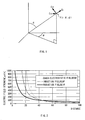
- the electric field E generated according to the distance r from the antenna can be represented in a simplified formula as shown below: where j is an imaginary unit, A a constant, and k is the number of waves.
- the electric field E can be roughly separated into a component which is in inverse proportion to the distance r raised to the third power (hereinafter, this component is referred to as a quasi-electrostatic field), a component which is in inverse proportion to the distance r raised to the second power (hereinafter, this component is referred to as an induction field) and a component which is linearly in inverse proportion to the distance r (hereinafter, this component is referred to as a radiation field).
- the radiation field is a component excellent in propagation capability, which does not rapidly attenuate even when the distance r is long, since it is only linearly in inverse proportion to the distance r, and therefore, it has been used as a common information transmission medium in the art of information communication.
- the induction field is a component with little transmission capability, which attenuates in inverse proportion to the distance r raised to the second power as the distance r lengthens, it has recently been used as an information transmission medium in a part of the art of information of communication.
- the quasi-electrostatic field is a component which rapidly attenuates in inverse proportion to the distance r raised to the third power and therefore does not a transmission capability and which appears in close proximity to an oscillation source only as oscillation. Therefore, it has not been utilized in the art of information communication where the radiation field and the induction field are premises.
- the present invention is adapted to send and receive information within a neighbor communication range, with a neighbor communication (hereinafter referred to as near field communication) approach using a quasi-electrostatic field among electric fields.
- near field communication a neighbor communication approach using a quasi-electrostatic field among electric fields.
- the electric field E shown in the above formula (1) is represented as an electric field at a position P (r, ⁇ , ⁇ ) at a predetermined distance from the origin as described in Figure 1.
- the electric field E ⁇ is "zero", and this means that there is not generated any electric field in the ⁇ direction from the position P ( Figure 1).
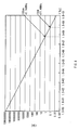
- Figures 2 and 3 shows the results obtained by qualitatively plotting the component's electric field strengths of the radiation field E1 ⁇ , the induction field E2 ⁇ and the quasi-electrostatic field E3 ⁇ based on the formulas (8).
- the component electric field strengths of the radiation field E1 ⁇ , the induction field E2 ⁇ and the quasi-electrostatic field E3 ⁇ are equal at a certain distance r (hereinafter referred to as a boundary point), and the radiation field E1 ⁇ is dominant in the distance from the boundary point.
- the quasi-electrostatic field E3 ⁇ is dominant.
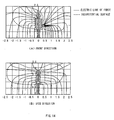
- the distance r from the origin to the boundary point varies according to the wavelength ⁇ . As shown in Figure 4, the longer the wavelength ⁇ is, the wider the range (the distance r from the origin to the boundary point) where the quasi-electrostatic field E3 ⁇ is dominant.
- the quasi-electrostatic field E3 ⁇ is dominant within the range where the distance r from the origin is "r ⁇ /2 ⁇ ", if the relative permittivity of the air ⁇ is assumed to be 1 and the wavelength in the air is assumed to be ⁇ .
- the information is sent and received in the space where the quasi-electrostatic field E3 ⁇ is dominant.
- a human body is very often electrified as suggested by the empirical fact that static electricity is felt in our everyday life.
- a quasi-electrostatic field is generated by electrification of the surface of a human body in response to the movement of the human body, it is not necessary to apply electricity to a human body to cause the human body to generate a quasi-electrostatic field but it is only necessary to electrify the human body.
- a human body is electrified by extremely little movement of charge (current); the electrification change is instantaneously conducted around the surface of the human body; and then an equipotential surface of a quasi-electrostatic field is formed substantially isotropically from the periphery. Furthermore, within the range satisfying the above formula (12) where the quasi-electrostatic field is dominant, the radiation field and the induction field does not have much influence. Consequently, the human body functions efficiently as an antenna. This has already been confirmed from the results of the experiments by the applicant.
- the present information is adapted to modulate a quasi-electrostatic field which is isotropically formed in the neighborhood of a human body by electrifying the human body according to particular information, and as a result, form a quasi-electrostatic field having information in the neighborhood of the human body, through which the information is sent and received.
- a walking quasi-electrostatic field As for displacement of the strength of a quasi-electrostatic field formed as the surface of a human body is electrified by the human body's walking motion (hereinafter, it is referred to as a walking quasi-electrostatic field), not only transfer of a charge between the passage surface and the plantar surface but also change in the exfoliation area (or the contact area) of the plantar surface relative to the passage surface and change in the distance between the passage surface and the plantar surface are closely involved.
- the electrification change on the surface of a human body caused by a walking motion of the human body reflects a pattern specific to the individual, which is generated by change in the electrostatic capacity and charge between the feet and the passage surface according to the track of the feet made by the walking motion and in which mutual movements of the right and left feet are combined.
- the left foot is completely in contact with the passage surface, irrespective of difference in the walking condition, according to walking characteristics.
- the walking motion described in the invention means a movement of walking on a flat passage surface without being especially conscious of the speed.
- the 8 Hz peak with the highest strength appears in a walking quasi-electrostatic field formed in the neighborhood of a human body when a walking motion is performed, therefore, if attempting to electrify a human body to form a quasi-electrostatic field having information in the neighborhood of a the human body, for the purpose of performing near field communication, the information may be destroyed by the 8 Hz peak.
- the present invention is adapted to avoid destruction of information by the 8 Hz peak by electrifying a human body according to information while avoiding the timing when such 8 Hz peak appears.
- One embodiment to which the present invention is applied will be now described below.
- reference numeral 1 denotes the entire configuration of a communication system to which the present invention is applied.
- the communication system comprises an authentication device 2 provided, for example, at the entrance of a company, and a mobile device (hereinafter referred to as a card device ) 3 detachably attached to a predetermined position of the arm of a human body (hereinafter referred to as a user) that utilizes the company in contact therewith.
- a card device a mobile device
- the authentication device 2 comprises an entrance/exit passage portion 4 provided for entrance and exit, and an exit door 5 openably and closably provided on the exit side of the entrance/exit passage portion 4, and is adapted to perform near field communication with the card device 3 provided on the user who is passing through the entrance/exit passage portion 4 and open the exit door 5 which is closed, as necessary.
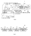
- the card device 3 comprises an electric field detection portion 10, a sending portion 20 and an electrification induction portion 30.
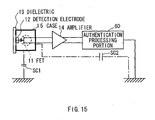
- the electric field detection portion 10 has a field effect transistor (hereinafter referred to as an FET) 11, and the gate of the FET 11 is connected to the user's epidermis OS, which is a detection target, via an detection electrode 12 and a dielectric 13 sequentially.
- the source and the drain of the FET 11 are connected to an amplifier 14.
- the electric field detection portion 10 is adapted to detect strength change of a walking quasi-electrostatic field HSE ( Figure 5) formed in the neighborhood of a user, which is caused by electrification of the surface of the user coming near to the entrance/exit passage portion 4, via the dielectric 13 and the detection electrode 12 sequentially, and send it to the sending portion 20 as an amplified walking electrification change signal S1 via the amplifier 14.
- HSE walking quasi-electrostatic field
- the electric field detection portion 10 is able to accurately detect the strength change substantially without being influenced by noises such as hum noises.
- the electric field detection portion 10 contacts the dielectric 13 directly with the user's epidermis OS and thereby can detect the strength change of the walking quasi-electrostatic field HSE with high sensitivity. Furthermore, by forming the dielectric 13 with soft vinyl chloride with a high permittivity, for example, the strength change can be detected with more sensitivity.
- the electric field detection portion 10 is provided with a conductive case 15 surrounding the periphery of the FET 11 in condition that the conductive case 15 is electrically separated from the FET 11, and thereby detection of strength change other than that in the walking quasi-electrostatic field HSE of the user can be avoided to the utmost extent.
- the walking motion described in this embodiment means a movement of walking on a flat passage surface without being especially conscious of the speed.
- the sending portion 20 comprises a low-pass filter (hereinafter referred to as an LPF) 22, a waveform processing portion 23 and a modulation circuit 24 and inputs an amplified walking electrification change signal S1 supplied by the electric field detection portion 10 into the LPF 22.
- LPF low-pass filter
- the LPF 22 abstracts a component with a low frequency at 20 Hz or below, for example, from the amplified walking electrification change signal S1 supplied by the amplifier 14 and sends it to the waveform processing portion 23 as a walking electrification change signal S2.
- the waveform processing portion 23 comprises an A/D (Analog/Digital) conversion portion 41, a peak detection portion 42, a peak prediction portion 43, and a masking time determination portion 44.
- the waveform processing portion 23 digitalizes the walking electrification change signal S2 supplied by the LPF 22 with the A/D conversion portion 41 and sends resultant walking electrification change data D1 to the peak detection portion 42.
- the peak detection portion 42 monitors the band of 8 Hz ⁇ 2 Hz in the electrification change waveforms in the walking electrification change data D1 supplied by the A/D conversion portion 41 and detects an 8 Hz peak Px which appears in this band.
- the peak detection portion 42 generates the time when the 8 Hz peak Px has been detected (hereinafter referred to as a current time) t(n) based on the clock in the card device 3 as current time data D2 and sends it to the peak prediction portion 43.
- the peak prediction portion 43 generates the future time t(n+1) as predicted time data D3 and sends the predicted time data D3 and the current time data D2 to the masking time determination portion 44.
- the masking time determination portion 44 determines the time zone (hereinafter referred to as a masking time zone) MTZ to be modulated by the modulation circuit 24 ( Figure 6) on the subsequent stage by calculating a start time ST(n) and a finish time FT(n) of the masking time zone MTZ.
- the masking time determination portion 44 determines the masking time zone MTZ, in which the 8 Hz peak Px is avoided, and sends it to the modulation circuit 24 ( Figure 6) as masking time data D4.
- the modulation circuit 24 performs modulation processing on ID (IDentifier) information D5 of the card device 3 supplied from a memory (not shown) in the card device 3 in which the ID information D5 is stored in advance, with a predetermined modulation method, to generate a modulated signal HS with a high frequency, and applies the modulated signal HS to an electrification-induction electrode 31 only during the masking time zone MTZ in the masking time data D4 supplied by the masking time determination portion 44.
- ID IDentifier
- the electrification-induction electrode 31 oscillates according to the frequency of the modulated signal HS supplied by the modulation circuit 24 only during the masking time zone MTZ, and a quasi-electrostatic field (modulated signal HS) is generated from the electrification-induction electrode 31 according to the oscillation.
- Such quasi-electrostatic field causes the user to be electrified only during the masking time zone MTZ according to the oscillation (modulated signal HS) of the electrification-induction electrode 31 and thereby act as an antenna, and as shown in Figure 8(C), a quasi-electrostatic field according to the oscillation (hereinafter referred to as an information-transmission quasi-electrostatic field) DSE ( Figure 5) isotropically spreads around the surface of the user.
- the sending portion 20 by changing the electrification condition of a user, the user is caused to act as an antenna, and as the result, an information-transmission quasi-electrostatic field DSE is formed on which the ID information D5 is superimposed.
- the user is electrified during the masking time zone MTZ ( Figure 8), in which the 8 Hz peak Px which appears with the highest strength in the strength change in the walking quasi-electrostatic field HSE is avoided, so that the ID information D5 superimposed on the information-transmission quasi-electrostatic field DSE can be prevented from being destroyed by the 8 Hz peak Px.
- the sending portion 20 is able to propagate, from the electrification-induction electrode 31 to the user, a quasi-electrostatic field oscillating in accordance with the frequency f which satisfies the following formula: f ⁇ c 2 ⁇ ⁇ r which is obtained by substituting the formula (10) into the formula (12) described above and rearranging the resultant formula.
- the sending portion 20 when performing near field communication by causing a user who is passing through the entrance/exit passage portion 4 to act as an antenna, the sending portion 20 is able to form the communication space as space (substantially closed space) where a non-propagating information-transmission quasi-electrostatic field DSE ( Figure 5) is always dominant, as described above with reference to Figures 3 and 4, and as a result, the communication output can be weakened to the extent that the communication contents are not propagated outside the communication space, and therefore, confidentiality of the communication contents can be secured more sufficiently.
- a non-propagating information-transmission quasi-electrostatic field DSE Figure 5
- the sending portion 20 is actually adapted to perform a sending process at the LPF 22, the waveform processing portion 23 and the modulation circuit 24 as software, in accordance with a predetermined sending program, under the control of a control portion not shown.
- the procedure for the sending process will be now described using the flowchart below.
- the sending portion 20 proceeds from the start step of a routine RT1 to the next step SP1, where it abstracts a low-frequency component of an amplified walking electrification change signal S1 supplied by the electric field detection portion 10 to generate a walking electrification change signal S2 and proceeds to the next step SP2.
- the sending portion 20 performs analog-digital conversion based on the walking electrification change signal S2 to generate walking electrification change data D1, and proceeds to the next step SP3.
- the sending portion 20 detects the 8 Hz peak Px ( Figure 8(A)) based on the walking electrification change data D1 and, after recognizing the current time t(n) thereof, proceeds to the next step SP4.
- the sending portion 20 predicts the future time t(n+1) of an 8 Hz peak Px which will be detected next to the 8 Hz peak Px detected at step SP3 from the above formula (13), and proceeds to the next step SP5.
- the sending portion 20 determines the masking time zone MTZ from the start time ST(n) to the finish time FT(n) from the above formulas (14) and (15), based on the current time t(n) recognized at step SP3 and the future time t(n+1) predicted at step SP5, and proceeds to the next step SP6.
- the sending portion 20 performs data modulation processing on the ID information D5 supplied from the memory in the card device 3 to generate a modulated signal HS, and then proceeds to the next step SP7.
- step SP7 by applying the modulated signal HS generated at step SP6 to the electrification induction electrode 31 to electrify the user, during the masking time zone MTZ calculated at step SP6, the sending portion 20 causes the user to act as an antenna and forms an information-transmission quasi-electrostatic field DSE ( Figure 5) on which the ID information D5 is superimposed, isotropically around the surface of the user ( Figure 8(C)), and then proceeds to step SP8.
- DSE information-transmission quasi-electrostatic field
- the information-transmission quasi-electrostatic field DSE ( Figure 5) formed isotropically around the surface of the user is acquired by the authentication device 2.
- the sending portion 20 determines whether or not the data modulation processing has been completed at step SP6. If it has not been completed, the sending portion 20 returns to step SP6 and performs the data modulation processing again. On the contrary, if it has been completed, the sending portion 20 proceeds to the next step SP9 and ends the sending process.
- the authentication device 2 comprises an electric field detection portion 50 provided, for example, on the internal surface of the entrance/exit passage portion 4 at the entrance side thereof and having the same configuration of the electric field detection portion 10 ( Figure 7), and an authentication processing portion 60 having the same configuration of the sending portion 20 except for a waveform processing portion 61 newly added instead of the modulation circuit 24 of the sending portion 20.
- the authentication device 2 detects strength change in an information-transmission quasi-electrostatic field DSE (the walking quasi-electrostatic field HSE) formed in the neighborhood of a user coming near to the entrance/exit passage portion 4 to pass through it, via the electric field detection portion 50 and the amplifier 14 sequentially as an amplified walking electrification change signal S11, almost at the same time as the card device 3 does; abstracts only a low-frequency component with the LPF 22; and sends it as an electrification change signal S12 to the waveform processing portion 23 and the authentication portion 61.
- DSE the walking quasi-electrostatic field HSE
- the waveform processing portion 23 performs each of the processings similar to those described above with reference to Figure 9 based on the electrification change signal S12 at the same time the processes are performed by the card device 3, and after that, it determines the masking time zone MTZ corresponding to the same time zone of the card device 3, and then sends it to the authentication portion 61 as masking time data D14.
- the authentication portion 61 performs a predetermined authentication process based on the masking time data D14 supplied by the waveform processing portion 23 and the electrification change signal S12 supplied by the LPF 22, using an ID list prestored in an internal memory (not shown).
- the authentication portion 61 first performs demodulation processing on the electrification change signal S12 supplied by LPF 22 in accordance with a predetermined demodulation method only during the masking time zone MTZ in the masking time data D14, and abstracts the ID information D5 superimposed on the electrification change signal S12 (the information-transmission quasi-electrostatic field DSE).
- the authentication portion 61 then checks the ID list stored in the internal memory against the ID information D5. Only when there is information corresponding to the ID information D5 in the ID list, it opens the exit door 5 of the entrance/exit passage portion 4.
- An authentication processing portion 60 is actually adapted to perform the authentication process by the LPF 22, the waveform processing portion 23 and the authentication portion 61 as software, in accordance with a predetermined sending program, under the control of a control portion not shown.
- the procedure for the authentication process will be now described using the flowchart below.
- the authentication processing portion 60 proceeds from the start step of the routine RT2 to the next step SP21, and generates electrification change data by performing each of the same processings as performed at the steps SP1 and SP2 ( Figure 9) by the card device 3 described above, on the amplified walking electrification change signal S11 detected and supplied by the electric field detection portion 50 at the same time when the card device 3 does, and then proceeds to the next step SP22.
- the authentication processing portion 60 determines a masking time zone MTZ by performing each of the same processings at the above steps SP3 to SP5 for the card device 3, on the electrification change data generated at step SP21, and then proceeds to the next step SP23.
- the authentication processing portion 60 by performing data demodulation processing on the electrification change data generated at step SP21 during the masking time zone MTZ determined at step SP22, abstracts the ID information D5 superimposed on the electrification change data, and then proceeds to the next step SP24.
- the authentication processing portion 60 checks the ID information D5 abstracted at step SP23 against the ID list prestored in the internal memory, and determines whether or not there is information corresponding to the ID information D5 in the ID list.
- the authentication processing portion 60 identifies that the user is not a person related to the company, and it proceeds to the next step SP25 and ends the authentication process.
- the authentication processing portion 60 proceeds to the next step SP25.
- step SP25 after opening the exit door 5 ( Figure 5) of the entrance/exit passage portion 4, the authentication processing portion 60 proceeds to the next step SP26 and ends the authentication process.
- the authentication processing portion 60 determines a masking time zone MTZ by performing the same processings as those by the card device 3 while detecting 8 Hz peaks Px that appear in almost the same cycle common to human bodies, irrespective of individuals, at the same time the card device 3 detects them, and thereby it can abstract ID information D5 superimposed on an information-transmission quasi-electrostatic field DSE formed in the neighborhood of a user by the card device 3, with high accuracy.
- the authentication system 1 is provided with a floor surface (hereinafter referred to as a route floor surface) Y1 of the entrance/exit passage portion 4 in such a condition that it is not grounded to the ground (hereinafter referred to as a building floor surface) Y2 but is separated from the building floor surface Y2 by predetermined space dx (a gap).
- a route floor surface a floor surface of the entrance/exit passage portion 4 in such a condition that it is not grounded to the ground (hereinafter referred to as a building floor surface) Y2 but is separated from the building floor surface Y2 by predetermined space dx (a gap).
- the electrostatic capacity between the feet of the user and the building floor surface Y2 can be reduced to be less than the electrostatic capacity between the user and the side-surface electrode 7 by the amount corresponding to the space dx between the route floor surface Y1 and the building floor surface Y2, and thereby leakage of the information-transmission quasi-electrostatic field DSE (the walking quasi-electrostatic field HSE) from the feet to the building floor surface Y2 can be prevented.
- DSE the walking quasi-electrostatic field HSE
- noises KN caused by inconsistency of the building floor surface Y2
- electrical discharge noises caused by electrically unstable condition due to a gap between joint surfaces of steel material in the building floor surface Y2 or rust of the steel material
- the communication system it is possible to form, in a more stable condition, the equipotential surface of the information-transmission quasi-electrostatic field DSE (the walking quasi-electrostatic field HSE) which is formed substantially isotropically from around the surface of the user when the user is electrified and the electrification change momentarily conducts over the periphery of the surface of the user, and therefore it is possible to stable near field communication.
- DSE the walking quasi-electrostatic field HSE
- the authentication device 2 of the communication system 1 is adapted to prevent leakage of a signal on the route from the detection electrode 12 to the authentication processing portion 60 via the FET 11 and the amplifier 14. Specifically, first, a conductive case 15 is electrically separated from the FET 11; and second, only the authentication processing portion 60 is connected to the ground on the receiving route.
- the authentication device 2 is adapted to reduce the electrostatic capacity SC1 between the FET 11 and the ground in comparison with the electrostatic capacity SC2 on the route from the FET 11 to the ground via the authentication processing portion 60, for example, by increasing the interval (height) between the FET 11 and the ground.
- the authentication device 2 can efficiently induce the information-transmission quasi-electrostatic field DSE (the walking quasi-electrostatic field HSE) detected by the detection electrode 52 to the authentication processing portion 60 via the FET 11, and thereby receive the information-transmission quasi-electrostatic field DSE ( Figure 5) formed around the user with high sensitivity.
- DSE the walking quasi-electrostatic field HSE
- the card device 3 and the authentication device 2 detect almost at the same time amplitude peaks that appear, almost in a constant cycle because of walking characteristics, in the band at a frequency of 8 ⁇ 2 [Hz] in a walking quasi-electrostatic field HSE formed in the neighborhood of a human body in response to a walking motion of the human body passing through the entrance/exit passage portion 4 as a communication route.
- a masking time zone MTZ is determined; the user is electrified by the electrification induction portion 30 according to ID information D5 only during the masking time zone MTZ and thereby the electrification condition of the user is modulated; and the ID information D5 is abstracted by detecting the electrification condition of the user via the electric field detection portion 50 and then demodulating it by the authentication processing portion 60.
- the ID information D5 can be sent and received in a condition that the ID information D5 superimposed on an information-transmission quasi-electrostatic field DSE can be prevented from being destroyed and in a condition that synchronization is almost sufficiently secured.
- the information can be sent and received in a condition that synchronization is more sufficiently secured.
- ID information D5 is sent and received by causing a human body to act as an antenna while avoiding 8 Hz peaks Px that appear with a high strength in the walking quasi-electrostatic field HSE formed in the neighborhood of the human body in response to a walking motion of the human body, so that the ID information D5 can be sent and received via the information-transmission quasi-electrostatic field DSE formed isotropically around the human body with the human body as an antenna while destruction of the information by the 8 Hz peak Px can be prevented.
- the degree of freedom in communication using a quasi-electrostatic field can be enhanced.
- the 8 Hz peak Px is detected by the peak detection portion 42 as peak detection means, from the strength displacement of the walking quasi-electrostatic field HSE formed around a human body in response to a walking motion of the human body.
- the present invention is not limited thereto, and the peak of the electric field displacement may be detected which is generated around the human body by various other bipedal motions such as brisk walking, up-and-down movement on stairs and stepping movement on the same place, that is, such movements that include a state in which the entire plantar surface of one foot is in contact with the ground and the tiptoe of the other foot has just left the ground.
- the amplitude peak in the walking waveform changes according to the speed of the movement performed from when the right foot (left foot) completely gets in contact with the ground until when the tiptoe of the right foot (left foot) has just left the ground. Therefore, by detecting the amplitude peak that appears at the frequency band according to the movement speed from when the right foot (left foot) in a bipedal motion to be detected is completely in contact with the ground until when the tiptoe of the right foot (left foot) has just left the ground as an index instead of the 8 Hz peak, the effect similar to that of the embodiment described above can be obtained.
- the predicted peak decreasing period ⁇ t1 and the predicted peak increasing period ⁇ t2 are changed based on the frequency band according to the movement speed from when the right foot (left foot) in a bipedal motion to be detected is completely in contact with the ground until when the tiptoe of the right foot (left foot) has just left the ground, then near field communication can be performed in a more stable condition.
- the card device 3 as a sending device is positioned on a predetermined portion of a user's arm in contact therewith.
- the present invention is not limited thereto, and the card device 3 may be positioned on various other portions of the epidermis of the user in contact therewith. For example, it may be embedded in a stud earring.
- the card device 3 is formed in a card shape.
- the present invention is not limited thereto, and the card device 3 may be formed in various other shapes. After all any shape may be possible only if it is of a mobile type.
- the route floor surface Y1 is provided for the entrance/exit passage portion 4 in a condition that it is separated from the building floor surface Y2 ( Figure 20) by predetermined space dx, as coupling preventing means for preventing a user and the ground from being electrically coupled with each other.
- the present invention is not limited thereto, and there may be provided a noise absorption/grounding line 80 laid on the route floor surface Y1 and grounded to the building floor surface Y2, as shown in Figure 16.
- the change in the electrification condition of the user may be detected by various other detection means such as an induction-electrode-type field strength meter for measuring the voltage induced by induction voltage, an induction-electrode-type modulation-amplification-system field strength meter for AC converting a direct signal obtained by an induction electrode using a chopper circuit, oscillation capacity and the like, an electro-optic-effect-type field strength meter for applying en electric field to material having an electro-optic effect to measure change in the light propagation characteristics caused in the material, and, only for the card device 3, an electrometer, a shunt-resistor-type field strength meter, a current-collection-type field strength meter and the like.
- an induction-electrode-type field strength meter for measuring the voltage induced by induction voltage
- an induction-electrode-type modulation-amplification-system field strength meter for AC converting a direct signal obtained by an induction electrode using a chopper circuit,
- electrification induction means is realized by the modulation circuit 24 and the electrification induction portion 30.
- the present invention is not limited thereto, and the electrification induction means may be realized by various other configurations.
- demodulation means is realized by the LPF 22 and the authentication portion 61.
- the present invention is not limited thereto, and the demodulation means may be realized by various other configurations.
- the peak prediction portion 43 and the masking time determination portion 44 as communication frame determination means determine a masking time zone MTZ shorter than the time width between the 8 Hz peak Px appearing at the current time and the 8 Hz peak Px at the future time as a communication frame in accordance with the formulas (14) and (15).
- the present invention is not limited thereto, and various other prediction formulas may be used to determine a communication frame.
- the authentication device 2 is applied as a second communication device provided on a predetermined control target.
- the present invention is not limited thereto, and a second communication provided on or in the neighborhood of a video tape recorder, a television set, electronics such as a mobile telephone or a personal computer, medical equipment, an automobile, a desk, and other control targets to be controlled, for example, can be broadly applied to the present invention. In this case, the same effect as that of the embodiment described above can be obtained.
- the present invention is not limited thereto and can be broadly applied to communication systems for various other purposes, such as a communication system with a communication route in the neighborhood of the desk, for opening the door of a desk as necessary when a user comes near to the desk, a communication system with a communication route in the neighborhood of a personal computer, for powering on the personal computer when a user comes near to the personal computer, and a communication system using a conveyance passage for conveying a predetermined identification target as a communication route, for switching conveyance passages as necessary when the identification target is conveyed to a predetermined position, that is, to any communication system that electrifies a human body according to information to cause the human body to act as an antenna and sends and receives information using a quasi-electrostatic field formed in the neighborhood
- each of the processings by a sending portion 20 or an authentication processing portion 60 is realized by a program.
- the present invention is not limited thereto, and a part or all of each processing may be realized by hardware means, such as an integrated circuit dedicated the processing.
- the program storage medium to have the program for executing the sending process or the authentication process installed and make it executable may be realized not only by a package media such as a flexible disk, a CD-ROM (Compact Disk-Read Only Memory), and a DVD (Digital Versatile Disc) but also by a semiconductor memory or a magnetic disk in which the program is temporarily or permanently stored.
- a wired or wires communication medium such as a local area network, the Internet, and digital satellite broadcasting, may be utilized, and the analysis program may be stored via various communication interfaces such as a router and a modem.
- the first and second communication devices detect an amplitude peak that appears at a predetermined frequency band in the displacement of a quasi-electrostatic field formed in the neighborhood of a human body in response to a bipedal motion of the human body passing through a predetermined communication route and determine a communication frame based on the detected amplitude peak.
- the first communication device modulates the quasi-electrostatic field according to information only during the determined communication frame, while the second device demodulates the modulated quasi-electrostatic field only during the communication frame.
- the human body is electrified in a condition that amplitude peaks that appear with a high strength in the walking quasi-electrostatic field formed in the neighborhood of the human body in response to the human body's walking motion are avoided, it is possible to send and receive information by electrifying the human body according to predetermined information and thereby causing the human body to act as an antenna in the quasi-electrostatic field formed isotropically around the surface of the human body while preventing destruction of the information by such peaks.
- the degree of freedom in communication using a quasi-electrostatic field can be enhanced.
- the present invention is adapted for the case of opening a door provided for a predetermined entrance/exit passage when the human body enters or exits from the entrance/exit passage, the case of unlocking a drawer provided for a desk as necessary when the human body comes near to the desk, and the case of switching conveyance passages as necessary when an article to be conveyed is conveyed to a predetermined conveyance passage.
Applications Claiming Priority (3)
| Application Number | Priority Date | Filing Date | Title |
|---|---|---|---|
| JP2003051868A JP4114143B2 (ja) | 2003-02-27 | 2003-02-27 | 通信システム、通信方法及び通信装置 |
| JP2003051868 | 2003-02-27 | ||
| PCT/JP2004/002374 WO2004077705A1 (fr) | 2003-02-27 | 2004-02-27 | Systeme, procede et appareil de communication |
Publications (1)
| Publication Number | Publication Date |
|---|---|
| EP1598964A1 true EP1598964A1 (fr) | 2005-11-23 |
Family
ID=32923377
Family Applications (1)
| Application Number | Title | Priority Date | Filing Date |
|---|---|---|---|
| EP20040715457 Withdrawn EP1598964A1 (fr) | 2003-02-27 | 2004-02-27 | Systeme, procede et appareil de communication |
Country Status (6)
| Country | Link |
|---|---|
| US (1) | US20060178109A1 (fr) |
| EP (1) | EP1598964A1 (fr) |
| JP (1) | JP4114143B2 (fr) |
| KR (1) | KR20050104400A (fr) |
| CN (1) | CN1754331A (fr) |
| WO (1) | WO2004077705A1 (fr) |
Cited By (2)
| Publication number | Priority date | Publication date | Assignee | Title |
|---|---|---|---|---|
| WO2007066976A1 (fr) * | 2005-12-08 | 2007-06-14 | Electronics And Telecommunications Research Institute | Systeme de communication utilisant la frequence en fonction de la securite ou de la distance de repetition |
| US7922084B2 (en) | 2005-12-20 | 2011-04-12 | Sony Corporation | System, apparatus, method and computer program for processing information |
Families Citing this family (12)
| Publication number | Priority date | Publication date | Assignee | Title |
|---|---|---|---|---|
| JP4586618B2 (ja) | 2005-04-18 | 2010-11-24 | ソニー株式会社 | 人体通信システム及び通信装置 |
| SI1889198T1 (sl) * | 2005-04-28 | 2015-02-27 | Proteus Digital Health, Inc. | Farma-informacijski sistem |
| US8078578B2 (en) * | 2005-10-14 | 2011-12-13 | Cisco Technology, Inc. | Sharing of presence-based time-zone information |
| JP4348637B2 (ja) * | 2006-01-16 | 2009-10-21 | ソニー株式会社 | 通信装置 |
| US8172762B2 (en) * | 2006-09-01 | 2012-05-08 | Proteus Biomedical, Inc. | Simultaneous blood flow and hematocrit sensor |
| JP4894500B2 (ja) * | 2006-12-22 | 2012-03-14 | ソニー株式会社 | 歩行波形処理方法及び歩行波形処理装置 |
| EP2146449A1 (fr) * | 2007-03-30 | 2010-01-20 | Alps Electric Co., Ltd. | Système de communication de données |
| KR20100075353A (ko) * | 2008-12-24 | 2010-07-02 | 한국전자통신연구원 | 인체영역 네트워크에서 인체의 일부를 안테나로 이용하는 통신 시스템 및 방법 |
| JP2012244516A (ja) * | 2011-05-23 | 2012-12-10 | Nippon Telegr & Teleph Corp <Ntt> | 電界通信システム |
| JP6057617B2 (ja) * | 2012-08-29 | 2017-01-11 | 国立大学法人 東京大学 | パルスギャップ推定装置、パルスギャップ推定方法及びプログラム |
| US9906272B2 (en) * | 2016-04-05 | 2018-02-27 | Nxp B.V. | Communications device |
| JP7311799B2 (ja) * | 2021-09-30 | 2023-07-20 | 東芝情報システム株式会社 | 電界式人体通信システム、送信装置及び受信装置 |
Family Cites Families (3)
| Publication number | Priority date | Publication date | Assignee | Title |
|---|---|---|---|---|
| JPH07170215A (ja) * | 1993-12-13 | 1995-07-04 | Sony Corp | 信号伝送方式 |
| KR100395863B1 (ko) * | 1995-05-08 | 2003-11-14 | 매사츄세츠 인스티튜트 오브 테크놀러지 | 신호송신매질로서인체를사용한비접촉센싱및신호송신용시스템 |
| JP3425347B2 (ja) * | 1996-12-12 | 2003-07-14 | 日本電信電話株式会社 | 人体経由情報伝達装置 |
-
2003
- 2003-02-27 JP JP2003051868A patent/JP4114143B2/ja not_active Expired - Fee Related
-
2004
- 2004-02-27 KR KR1020057015831A patent/KR20050104400A/ko not_active Application Discontinuation
- 2004-02-27 CN CNA200480005347XA patent/CN1754331A/zh active Pending
- 2004-02-27 EP EP20040715457 patent/EP1598964A1/fr not_active Withdrawn
- 2004-02-27 WO PCT/JP2004/002374 patent/WO2004077705A1/fr not_active Application Discontinuation
- 2004-02-27 US US10/546,870 patent/US20060178109A1/en not_active Abandoned
Non-Patent Citations (1)
| Title |
|---|
| See references of WO2004077705A1 * |
Cited By (3)
| Publication number | Priority date | Publication date | Assignee | Title |
|---|---|---|---|---|
| WO2007066976A1 (fr) * | 2005-12-08 | 2007-06-14 | Electronics And Telecommunications Research Institute | Systeme de communication utilisant la frequence en fonction de la securite ou de la distance de repetition |
| CN101336521B (zh) * | 2005-12-08 | 2011-09-07 | 韩国电子通信研究院 | 使用根据安全或传送距离的频率的通信系统 |
| US7922084B2 (en) | 2005-12-20 | 2011-04-12 | Sony Corporation | System, apparatus, method and computer program for processing information |
Also Published As
| Publication number | Publication date |
|---|---|
| KR20050104400A (ko) | 2005-11-02 |
| JP4114143B2 (ja) | 2008-07-09 |
| JP2004266388A (ja) | 2004-09-24 |
| US20060178109A1 (en) | 2006-08-10 |
| WO2004077705A1 (fr) | 2004-09-10 |
| CN1754331A (zh) | 2006-03-29 |
Similar Documents
| Publication | Publication Date | Title |
|---|---|---|
| EP1598009A1 (fr) | Systeme d'authentification | |
| EP1598965A1 (fr) | Systeme de communication | |
| EP1598964A1 (fr) | Systeme, procede et appareil de communication | |
| US7922084B2 (en) | System, apparatus, method and computer program for processing information | |
| JP2004282733A (ja) | 通信システム | |
| US7202773B1 (en) | Authentication information communication system and method, portable information processing device and program furnishing medium | |
| US7693174B2 (en) | Communication collision avoidance system | |
| US7597250B2 (en) | RFID reader with multiple interfaces | |
| US20070002815A1 (en) | Communication system, communication method and program | |
| US9894171B2 (en) | Media exposure and verification utilizing inductive coupling | |
| WO2004109325A1 (fr) | Systeme de detection de distance | |
| US20030072475A1 (en) | Verification techniques for biometric identification systems | |
| US20080123599A1 (en) | Communication System, Communication Device And Method, And Program | |
| EP0824889A1 (fr) | Système de transmission utilisant le corps humain comme dispositif à guide d'onde | |
| US20110294420A1 (en) | Communication system | |
| US20070067463A1 (en) | Communications system, communications apparatus, method and program | |
| US7890055B1 (en) | Touch field compound field detector personal ID | |
| JP3350226B2 (ja) | データ転送受信装置 |
Legal Events
| Date | Code | Title | Description |
|---|---|---|---|
| PUAI | Public reference made under article 153(3) epc to a published international application that has entered the european phase |
Free format text: ORIGINAL CODE: 0009012 |
|
| 17P | Request for examination filed |
Effective date: 20050825 |
|
| AK | Designated contracting states |
Kind code of ref document: A1 Designated state(s): AT BE BG CH CY CZ DE DK EE ES FI FR GB GR HU IE IT LI LU MC NL PT RO SE SI SK TR |
|
| AX | Request for extension of the european patent |
Extension state: AL LT LV MK |
|
| DAX | Request for extension of the european patent (deleted) | ||
| RBV | Designated contracting states (corrected) |
Designated state(s): DE FR GB |
|
| STAA | Information on the status of an ep patent application or granted ep patent |
Free format text: STATUS: THE APPLICATION HAS BEEN WITHDRAWN |
|
| 18W | Application withdrawn |
Effective date: 20071121 |