Technical Field
-
The present invention relates to a communication system and
is preferably applicable to a communication system for sending
and receiving information via an electric field, for example.
Background Art
-
Conventionally, communication systems have been adapted to
send and receive information using a radiation field (radio
waves), for example, between mobile telephones, and send and
receive information via electromagnetic induction, for example,
between the coil in a data reader/writer provided on a ticket
checking and collecting machine at a station and the coil in an
IC card.
-
Recently, there have been proposed communication systems
which are provided with a human-body-side communication device
fitted in contact with the skin of a human body and an equipment-side
communication device in the neighborhood of the user as
shown in Table 1 below. In these communication systems, an
alternating voltage is applied to the human body via the
electrode of the human-body-side communication device, and as a
result, there is caused an electrostatic induction phenomenon at
the electrode of the equipment-side communication device by the
action of a capacitor using a human body intervening between the
electrodes of the communication device on the human body side and
the communication device on the equipment side as a medium.
Using the electrostatic induction phenomenon, information is sent
and received (see Non-patent document 1, for example).
-
In addition to the communication systems shown in Table 1,
there have been proposed a lot of communication systems adapted
to send and receive information utilizing the electrostatic
induction phenomenon caused at a receiving electrode by the
action of a capacitor using a human body intervening between
sending and receiving electrodes as a medium (see Patent
documents 1 to 9 and Non-patent documents 2 to 5).
- [Patent document 1] National Publication of International
Patent Application No. 11-509380
- [Patent document 2] Patent No. 3074644
- [Patent document 3] Japanese Patent Laid-Open No. 10-228524
- [Patent document 4] Japanese Patent Laid-Open No. 10-229357
- [Patent document 5] Japanese Patent Laid-Open No. 2001-308803
- [Patent document 6] Japanese Patent Laid-Open No. 2000-224083
- [Patent document 7] Japanese Patent Laid-Open No. 2001-223649
- [Patent document 8] Japanese Patent Laid-Open No. 2001-308803
- [Patent document 9] Japanese Patent Laid-Open No. 2002-9710
- [Non-patent document 1] Internet
<URL:http://www.mew.co.jp/press/0103/0103-7.htm> (retrieved on
January 20, 2003) - [Non-patent document 2] "Development of Information
Communication Device with Human Body Used as Transmission Line"
by Keisuke Hachisuka, Anri Nakata, Kenji Shiba, Ken Sasaki,
Hiroshi Hosaka and Kiyoshi Itao (Tokyo University); March 1, 2002
(Collected Papers for Academic Lectures on Micromechatronics,
Vol., 2002, Spring, pp. 27-28)
- [Non-patent document 3] "Development of Communication
System within Organism" by Anri Nakata; Keisuke Hachisuka, Kenji
Shiba, Ken Sasaki, Hiroshi Hosaka and Kiyoshi Itao (Tokyo
University); 2002 (Collected Papers for Academic Lectures for
Japan Society of Precision Engineering Conference, Spring, p.640)
- [Non-patent document 4] "Review on Modeling of
Communication System Utilizing Human Body as Transmission Line"
by Katsuyuki Fujii (Chiba University), Koichi Date (Chiba
University), Shigeru Tajima (Sony Computer Science Laboratories,
Inc.); March 1, 2002 (Technical Reports by The Institute of Image
Information and Television Engineers Vol. 26, No. 20, pp. 13-18)
- [Non-patent document 5] "Development of Information
Communication Device with Human Body Used as Transmission Line"
by Keisuke Hachisuka, Anri Nakata, Kento Takeda, Ken Sasaki,
Hiroshi Hosaka, Kiyoshi Itao (Graduate School of Science of New
Region Creation, Tokyo University) and Kenji Shiba (Science and
Engineering Course, Tokyo University of Science); March 18, 2002
(Micromechatronics Vol. 46; No. 2; pp. 53-64)
-
-
In these communication systems with such a configuration,
since the action of a capacitor using a human body intervening
between sending and receiving electrodes as a medium is the
premise of physical action, the communication strength in
communication between the electrodes depends on the area of the
electrodes.
-
Furthermore, since the action of a capacitor using a human
body intervening between sending and receiving electrodes as a
medium is the premise of physical action, it is physically
impossible, when the sending electrode is fitted to the human's
right wrist, for example, to communicate in directions other than
the direction from the human's right wrist to the fingertip.
When the sending electrode is fitted near the human's chest,
communication in directions other than the forward direction from
the human's chest is physically impossible.
-
As described above, in communication systems, since the
action of a capacitor using a human body intervening between
sending and receiving electrodes as a medium is the premise of
physical action, there have been a problem that the communication
direction is restricted by the position of the electrode fitted
to a human body as well as a problem that the degree of freedom
in communication is low because the communication strength
depends on the electrode area.
Disclosure of the Invention
-
The present invention has been made in consideration of the
above problems and proposes a communication system, a
communication method and a communication device capable of
enhancing the degree of freedom in communication.
-
In order to solve the above problems, according to the
present invention, in a communication system comprising a first
communication device and a second communication device for
sending and receiving information via a quasi-electrostatic field,
the first and second communication devices detect an amplitude
peak that appears at a predetermined frequency band in the
displacement of a quasi-electrostatic field formed in the
neighborhood of a human body in response to a bipedal motion of
the human body passing through a predetermined communication
route and determine a communication frame based on the detected
amplitude peak. After that, the first communication device
modulates the quasi-electrostatic field according to information
only during the determined communication frame, while the second
device demodulates the modulated quasi-electrostatic field only
during the communication frame.
-
In this case, in the communication system, since the human
body is electrified in a condition that amplitude peaks that
appear with a high strength in the walking quasi-electrostatic
field formed in the neighborhood of the human body in response to
the human body's walking motion are avoided, it is possible to
send and receive information by electrifying the human body
according to predetermined information and thereby causing the
human body to act as an antenna in the quasi-electrostatic field
formed isotropically around the surface of the human body while
preventing destruction of the information by such peaks.
Brief Description of the Drawings
-
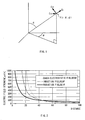
- Figure 1 is a schematic diagram provided to explain a polar
coordinate system;
- Figure 2 is a graph showing relative strength change (1) of
each electric field relative to the distance;
- Figure 3 is a graph showing relative strength change (2) of
each electric field relative to the distance;
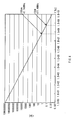
- Figure 4 is a graph showing the relation between wavelength
and distance in the vacuum;
- Figure 5 shows the entire configuration of a communication
system to which the present invention is applied;
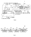
- Figure 6 is a schematic block diagram showing the
configuration of a card device;
- Figure 7 is a block diagram showing the configuration of a
waveform processing portion;
- Figure 8 is a schematic diagram provided to explain a
walking waveform;
- Figure 9 is a flowchart showing a procedure for sending
process;
- Figure 10 is a schematic block diagram showing the
configuration of an authentication device;
- Figure 11 is a flowchart showing a procedure for an
authentication process;
- Figure 12 is a schematic diagram provided to explain the
floor surface of the authentication device;
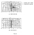
- Figure 13 is a schematic diagram showing the equipotential
surface of a quasi-electrostatic field to be formed when a human
body is caused to act as an ideal dipole antenna;
- Figure 14 is a schematic diagram showing the equipotential
surface of a quasi-electrostatic field according to this
embodiment;
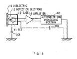
- Figure 15 is a schematic diagram provided to explain
prevention of electrical leakage; and
- Figure 16 is a schematic diagram showing the configuration
of a noise absorption/grounding line.
-
Best Mode for Carrying Out the Invention
-
The present invention is now described in detail with
reference to the drawings.
(1) Summary of the invention
-
According to the invention, information is sent and received
using an electric field. The summary of the present invention is
now described in terms of the relation with the electric field.
(1-1) Electric field
-
Generally, when current flows through an electric dipole
(dipole antenna), the electric field E generated according to the
distance r from the antenna can be represented in a simplified
formula as shown below:
where j is an imaginary unit, A a constant, and k is the number
of waves.
-
As shown in the above formula (1), the electric field E can
be roughly separated into a component which is in inverse
proportion to the distance r raised to the third power
(hereinafter, this component is referred to as a quasi-electrostatic
field), a component which is in inverse proportion
to the distance r raised to the second power (hereinafter, this
component is referred to as an induction field) and a component
which is linearly in inverse proportion to the distance r
(hereinafter, this component is referred to as a radiation field).
-
The radiation field is a component excellent in propagation
capability, which does not rapidly attenuate even when the
distance r is long, since it is only linearly in inverse
proportion to the distance r, and therefore, it has been used as
a common information transmission medium in the art of
information communication.
-
Though the induction field is a component with little
transmission capability, which attenuates in inverse proportion
to the distance r raised to the second power as the distance r
lengthens, it has recently been used as an information
transmission medium in a part of the art of information of
communication.
-
The quasi-electrostatic field is a component which rapidly
attenuates in inverse proportion to the distance r raised to the
third power and therefore does not a transmission capability and
which appears in close proximity to an oscillation source only as
oscillation. Therefore, it has not been utilized in the art of
information communication where the radiation field and the
induction field are premises.
-
The present invention is adapted to send and receive
information within a neighbor communication range, with a
neighbor communication (hereinafter referred to as near field
communication) approach using a quasi-electrostatic field among
electric fields.
(1-2) Quasi-electrostatic field
-
The quasi-electrostatic field is now described in more
detail. First, the electric field E shown in the above formula
(1) is represented as an electric field at a position P (r, , )
at a predetermined distance from the origin as described in
Figure 1.
-
In this case, if it is assumed that a charge q and a charge
-q exist separated by a distance δ and the charge q changes to
"Qcosωt" at a time t, then the electric fields Er, E and E at
the position P (r, , ) can be represented as the following
formulas, respectively, with the position of the charge q as the
origin:
Er = Qcosωtσcos2πεr 3 (1+ jkr)exp(-jkr) E = Qcosωtσsin4πεr 3 (1+ jkr +(jkr)2) exp(-jkr) E = 0
-
In the formulas (2), the electric field E is "zero", and
this means that there is not generated any electric field in the
direction from the position P (Figure 1).
-
If the component which is linearly in inverse proportion to
the distance r (that is, the radiation field) is separated from
the electric fields Er and E represented in the formulas (2),
then the radiation field E1r and E1 at the position P (r, , )
are represented as the following formulas:
E1r = 0 E1 = Qcosωtσsin4πεr (jk)2exp(-jkr)
If the component which is in inverse proportion to the distance r
raised to the second power (that is, the induction field) is
separated from the electric fields Er and E represented in the
formulas (2), then the induction fields E2r and E2 at the
position P (r, , ) are represented as the following formulas:
E2r = Qcosωtσcos2πεr 2 jk·exp(-jkr) E2 = Qcosωtσsin4πεr 2 jk·exp(-jkr)
Furthermore, if the component which is in inverse proportion to
the distance r raised to the third power (that is, the quasi-electrostatic
field) is separated from the electric fields Er and
E represented in the formulas (2), then the quasi-electrostatic
fields E3r and E3 at the position P (r, , ) are represented as
the following formulas:
E3r = Qcosωtσcos2πεr 3 E3 = Qcosωtσsin4πεr 3
-
In the formulas (3), only the radiation field E1r is "zero",
and this means that there is not generated any radiation field in
the tangent direction from the position P (Figure 1).
-
Now, in order to show the component's electric field
strength of each of the radiation field, the induction field and
the quasi-electrostatic field at a distance r, the radiation
field E1, the induction field E2 and the quasi-electrostatic
field E3 in the formulas (3) to (5) are now described in more
detail.
-
The number of waves k [m-1] is in the relation shown as the
following formula, where the angular frequency is denoted by ω
and the light velocity is denoted by c:
k = ωc
If the number of waves k is substituted into the formula (6), the
"j·exp(-jkr)" is removed since it is beyond the discussion here,
and the "cosωt" is assumed to be one (1) since the maximum
change with time between the charge q and the charge -q is to be
considered, then the following formulas are obtained:
Radiation field
E1 = Qσsin4πεr 3 [ωc r]2
Induction field
E2 = Qσsin4πεr 3 ωc r
Quasi-elctrostatic field
E3 = Qσsin4πεr 3
If the formulas (7) are rearranged by substituting the distance δ,
the charge q (= Q) and the with one (1), 0.001 [C] and π/2,
respectively, then the following formulas are obtained:
Radiation field
E1 = 0.0014πε0 r [ωc ]2
Induction field
E2 = 0.0014πε0 r 2 ωc
Quasi-elctrostatic field
E3 = 0.0014πε0 r 3
-
Figures 2 and 3 shows the results obtained by qualitatively
plotting the component's electric field strengths of the
radiation field E1, the induction field E2 and the quasi-electrostatic
field E3 based on the formulas (8).
-
However, in Figures 2 and 3, the component's electric field
strengths at a frequency of 1 [MHz] are shown, and in Figure 3, a
relation between component's distance and electric field strength
shown in Figure 2 is shown by a graph with a measure of logarithm.
-
Especially apparent from Figure 3, the component electric
field strengths of the radiation field E1, the induction field
E2 and the quasi-electrostatic field E3 are equal at a certain
distance r (hereinafter referred to as a boundary point), and the
radiation field E1 is dominant in the distance from the boundary
point. On the contrary, in the neighbor before the boundary
point, the quasi-electrostatic field E3 is dominant.
-
At the boundary point, the following formula is established
according to the above formulas (8):
ωc · r = 1
The light velocity c is in the relation shown by the following
formula, where the wavelength is denoted by λ and the frequency
is denoted by f:
c=λ · f
The angular frequency ω is in the relation shown by the
following formula:
ω=2 π f
Then, by substituting the formula (10) and the formula (11) into
the formula (9) and rearranging the formula (9), the following
formula is obtained:
r = λ2π
-
According to the formula (12), the distance r from the
origin to the boundary point varies according to the wavelength λ.
As shown in Figure 4, the longer the wavelength λ is, the wider
the range (the distance r from the origin to the boundary point)
where the quasi-electrostatic field E3 is dominant.
-
To sum up the above description, the quasi-electrostatic
field E3 is dominant within the range where the distance r from
the origin is "r<λ/2π", if the relative permittivity of the air ε
is assumed to be 1 and the wavelength in the air is assumed to be
λ.
-
In the present invention, by selecting the range satisfying
the formula (12) when sending and receiving information with the
near field communication approach, the information is sent and
received in the space where the quasi-electrostatic field E3 is
dominant.
(1-3) A quasi-electrostatic field and a human body
-
Though it is necessary to apply current to a human body to
cause the human body to generate a radiation field or an
induction field, it is physically difficult to efficiently apply
current to the human body because the impedance of a human body
is very high. It is also physiologically undesirable to apply
current to a human body. As for static electricity, however, the
situation is completely different.
-
That is, a human body is very often electrified as suggested
by the empirical fact that static electricity is felt in our
everyday life. As it is known that a quasi-electrostatic field
is generated by electrification of the surface of a human body in
response to the movement of the human body, it is not necessary
to apply electricity to a human body to cause the human body to
generate a quasi-electrostatic field but it is only necessary to
electrify the human body.
-
That is, a human body is electrified by extremely little
movement of charge (current); the electrification change is
instantaneously conducted around the surface of the human body;
and then an equipotential surface of a quasi-electrostatic field
is formed substantially isotropically from the periphery.
Furthermore, within the range satisfying the above formula (12)
where the quasi-electrostatic field is dominant, the radiation
field and the induction field does not have much influence.
Consequently, the human body functions efficiently as an antenna.
This has already been confirmed from the results of the
experiments by the applicant.
-
As a near field communication technology, the present
information is adapted to modulate a quasi-electrostatic field
which is isotropically formed in the neighborhood of a human body
by electrifying the human body according to particular
information, and as a result, form a quasi-electrostatic field
having information in the neighborhood of the human body, through
which the information is sent and received.
(1-4) A quasi-electrostatic field and a walking motion of a
human body
-
As already stated, the surface of a human body is
electrified in response to a movement of the human body.
Description will be now made on the relation between walking, one
of major movements of a human body, and electrification in more
detail. Such relation is already disclosed in Japanese Patent
Application No. 2002-314920 by the applicant.
-
That is, as for displacement of the strength of a quasi-electrostatic
field formed as the surface of a human body is
electrified by the human body's walking motion (hereinafter, it
is referred to as a walking quasi-electrostatic field), not only
transfer of a charge between the passage surface and the plantar
surface but also change in the exfoliation area (or the contact
area) of the plantar surface relative to the passage surface and
change in the distance between the passage surface and the
plantar surface are closely involved.
-
In other words, the electrification change on the surface of
a human body caused by a walking motion of the human body
reflects a pattern specific to the individual, which is generated
by change in the electrostatic capacity and charge between the
feet and the passage surface according to the track of the feet
made by the walking motion and in which mutual movements of the
right and left feet are combined.
-
At the instant when the tiptoe of the right foot (left foot)
has completely left the ground, the left foot (right foot) is
completely in contact with the passage surface, irrespective of
difference in the walking condition, according to walking
characteristics.
-
Accordingly, in such a condition, mutual electrification
action (interference action) between the right and left feet does
not occur, and in displacement of strength of the walking quasi-electrostatic
field in this condition, the highest peak amplitude
appears specifically within the band of 8 Hz±2 Hz.
-
As for details of the amplitude peak which appears in a
walking quasi-electrostatic field (hereinafter referred to as the
8 Hz peak), see Japanese Patent Application No. 2002-314920
(paragraph No. [0024] on p. 5 to paragraph No. [0056] on p.12)
already disclosed by the applicant. The walking motion described
in the invention means a movement of walking on a flat passage
surface without being especially conscious of the speed.
-
As described above, the 8 Hz peak with the highest strength
appears in a walking quasi-electrostatic field formed in the
neighborhood of a human body when a walking motion is performed,
therefore, if attempting to electrify a human body to form a
quasi-electrostatic field having information in the neighborhood
of a the human body, for the purpose of performing near field
communication, the information may be destroyed by the 8 Hz peak.
-
Therefore, the present invention is adapted to avoid
destruction of information by the 8 Hz peak by electrifying a
human body according to information while avoiding the timing
when such 8 Hz peak appears. One embodiment to which the present
invention is applied will be now described below.
(2) One embodiment of the present invention
(2-1) Entire configuration of a communication system
-
In Figure 5, reference numeral 1 denotes the entire
configuration of a communication system to which the present
invention is applied. The communication system comprises an
authentication device 2 provided, for example, at the entrance of
a company, and a mobile device (hereinafter referred to as a card
device ) 3 detachably attached to a predetermined position of the
arm of a human body (hereinafter referred to as a user) that
utilizes the company in contact therewith.
-
The authentication device 2 comprises an entrance/exit
passage portion 4 provided for entrance and exit, and an exit
door 5 openably and closably provided on the exit side of the
entrance/exit passage portion 4, and is adapted to perform near
field communication with the card device 3 provided on the user
who is passing through the entrance/exit passage portion 4 and
open the exit door 5 which is closed, as necessary.
(2-2) Configuration of a card device
-
As shown in Figure 6, the card device 3 comprises an
electric field detection portion 10, a sending portion 20 and an
electrification induction portion 30.
-
The electric field detection portion 10 has a field effect
transistor (hereinafter referred to as an FET) 11, and the gate
of the FET 11 is connected to the user's epidermis OS, which is a
detection target, via an detection electrode 12 and a dielectric
13 sequentially. The source and the drain of the FET 11 are
connected to an amplifier 14.
-
The electric field detection portion 10 is adapted to detect
strength change of a walking quasi-electrostatic field HSE
(Figure 5) formed in the neighborhood of a user, which is caused
by electrification of the surface of the user coming near to the
entrance/exit passage portion 4, via the dielectric 13 and the
detection electrode 12 sequentially, and send it to the sending
portion 20 as an amplified walking electrification change signal
S1 via the amplifier 14.
-
In this case, since strength change of the walking quasi-electrostatic
field HSE formed in response to a walking motion of
a user appears at an infrasonic frequency band, the electric
field detection portion 10 is able to accurately detect the
strength change substantially without being influenced by noises
such as hum noises.
-
The electric field detection portion 10 contacts the
dielectric 13 directly with the user's epidermis OS and thereby
can detect the strength change of the walking quasi-electrostatic
field HSE with high sensitivity. Furthermore, by forming the
dielectric 13 with soft vinyl chloride with a high permittivity,
for example, the strength change can be detected with more
sensitivity.
-
In addition to the above configuration, the electric field
detection portion 10 is provided with a conductive case 15
surrounding the periphery of the FET 11 in condition that the
conductive case 15 is electrically separated from the FET 11, and
thereby detection of strength change other than that in the
walking quasi-electrostatic field HSE of the user can be avoided
to the utmost extent.
-
The walking motion described in this embodiment means a
movement of walking on a flat passage surface without being
especially conscious of the speed.
-
The sending portion 20 comprises a low-pass filter
(hereinafter referred to as an LPF) 22, a waveform processing
portion 23 and a modulation circuit 24 and inputs an amplified
walking electrification change signal S1 supplied by the electric
field detection portion 10 into the LPF 22.
-
The LPF 22 abstracts a component with a low frequency at 20
Hz or below, for example, from the amplified walking
electrification change signal S1 supplied by the amplifier 14 and
sends it to the waveform processing portion 23 as a walking
electrification change signal S2.
-
As shown in Figure 7, the waveform processing portion 23
comprises an A/D (Analog/Digital) conversion portion 41, a peak
detection portion 42, a peak prediction portion 43, and a masking
time determination portion 44. The waveform processing portion
23 digitalizes the walking electrification change signal S2
supplied by the LPF 22 with the A/D conversion portion 41 and
sends resultant walking electrification change data D1 to the
peak detection portion 42.
-
As shown in Figure 8 (A), the peak detection portion 42
monitors the band of 8 Hz±2 Hz in the electrification change
waveforms in the walking electrification change data D1 supplied
by the A/D conversion portion 41 and detects an 8 Hz peak Px
which appears in this band.
-
Then, the peak detection portion 42 generates the time when
the 8 Hz peak Px has been detected (hereinafter referred to as a
current time) t(n) based on the clock in the card device 3 as
current time data D2 and sends it to the peak prediction portion
43.
-
The peak prediction portion 43 holds the time (hereinafter
the time is called as a past time) t(n-1) of a past 8 Hz peak Px
stored in an internal memory, which had appeared immediately
before the 8 Hz peak Px which appeared at the current time t(n),
and predicts, based on the current time t(n) and the past time
t(n-1), the time (hereinafter referred to as a future time)
t(n+1) of a future 8 Hz peak Px which will appear immediately
after the 8 Hz peak Px which appeared at the current time by
adding the difference between the current time t(n) and the past
time t(n-1) to the current time t(n) as represented by the
following formula:
t (n + 1) = t (n) + (t (n) - t (n - 1))
-
The peak prediction portion 43 generates the future time
t(n+1) as predicted time data D3 and sends the predicted time
data D3 and the current time data D2 to the masking time
determination portion 44.
-
As shown in Figure 8 (B), the masking time determination
portion 44 determines the time zone (hereinafter referred to as a
masking time zone) MTZ to be modulated by the modulation circuit
24 (Figure 6) on the subsequent stage by calculating a start time
ST(n) and a finish time FT(n) of the masking time zone MTZ.
-
Specifically, the masking time determination portion 44
presets in advance a period (hereinafter referred to as a
predicted peak decreasing period) Δt1 which begins when the 8 Hz
peak Px appears and ends when a predetermined amplitude level is
reached, and calculates the start time ST(n) of the masking time
zone MTZ in accordance with the following formula:
ST(n) = t(n) + Δt1
-
The masking time determination portion 44 also presets in
advance a period (hereinafter referred to as a predicted peak
increasing period) Δt2 which begins at a predetermined amplitude
level and ends when the 8 Hz peak Px appears, and calculates the
finish time FT(n) of the masking time zone MTZ in accordance with
the following formula:
FT(n) = t (n+1) - Δt2
-
In this way, by removing the predicted peak decreasing
period Δt1 and the predicted peak increasing period Δt2 preset
in advance from the interval (hereinafter referred to as an 8 Hz
peak interval) PS between an 8 Hz peak Px and the 8 Hz peak Px
which appears immediately after the 8 Hz peak Px), the masking
time determination portion 44 determines the masking time zone
MTZ, in which the 8 Hz peak Px is avoided, and sends it to the
modulation circuit 24 (Figure 6) as masking time data D4.
-
The modulation circuit 24 performs modulation processing on
ID (IDentifier) information D5 of the card device 3 supplied from
a memory (not shown) in the card device 3 in which the ID
information D5 is stored in advance, with a predetermined
modulation method, to generate a modulated signal HS with a high
frequency, and applies the modulated signal HS to an
electrification-induction electrode 31 only during the masking
time zone MTZ in the masking time data D4 supplied by the masking
time determination portion 44.
-
The electrification-induction electrode 31 oscillates
according to the frequency of the modulated signal HS supplied by
the modulation circuit 24 only during the masking time zone MTZ,
and a quasi-electrostatic field (modulated signal HS) is
generated from the electrification-induction electrode 31
according to the oscillation.
-
Such quasi-electrostatic field (modulated signal HS) causes
the user to be electrified only during the masking time zone MTZ
according to the oscillation (modulated signal HS) of the
electrification-induction electrode 31 and thereby act as an
antenna, and as shown in Figure 8(C), a quasi-electrostatic field
according to the oscillation (hereinafter referred to as an
information-transmission quasi-electrostatic field) DSE (Figure
5) isotropically spreads around the surface of the user.
-
As described above, in the sending portion 20, by changing
the electrification condition of a user, the user is caused to
act as an antenna, and as the result, an information-transmission
quasi-electrostatic field DSE is formed on which the ID
information D5 is superimposed.
-
In this case, in the sending portion 20, the user is
electrified during the masking time zone MTZ (Figure 8), in which
the 8 Hz peak Px which appears with the highest strength in the
strength change in the walking quasi-electrostatic field HSE is
avoided, so that the ID information D5 superimposed on the
information-transmission quasi-electrostatic field DSE can be
prevented from being destroyed by the 8 Hz peak Px.
-
If the relative permittivity of the air ε is represented by
1, the wavelength in the air is represented by λ, the maximum
distance for communication between the card device 3 and the
authentication device 2 is represented by r, and the frequency of
the modulated signal HS to be supplied to the electrification-induction
electrode 31 is represented by f, then the sending
portion 20 is able to propagate, from the electrification-induction
electrode 31 to the user, a quasi-electrostatic field
oscillating in accordance with the frequency f which satisfies
the following formula:
f < c2 π · r
which is obtained by substituting the formula (10) into the
formula (12) described above and rearranging the resultant
formula.
-
Accordingly, when performing near field communication by
causing a user who is passing through the entrance/exit passage
portion 4 to act as an antenna, the sending portion 20 is able to
form the communication space as space (substantially closed
space) where a non-propagating information-transmission quasi-electrostatic
field DSE (Figure 5) is always dominant, as
described above with reference to Figures 3 and 4, and as a
result, the communication output can be weakened to the extent
that the communication contents are not propagated outside the
communication space, and therefore, confidentiality of the
communication contents can be secured more sufficiently.
-
The sending portion 20 is actually adapted to perform a
sending process at the LPF 22, the waveform processing portion 23
and the modulation circuit 24 as software, in accordance with a
predetermined sending program, under the control of a control
portion not shown. The procedure for the sending process will be
now described using the flowchart below.
-
As shown in Figure 9, the sending portion 20 proceeds from
the start step of a routine RT1 to the next step SP1, where it
abstracts a low-frequency component of an amplified walking
electrification change signal S1 supplied by the electric field
detection portion 10 to generate a walking electrification change
signal S2 and proceeds to the next step SP2.
-
At step SP2, the sending portion 20 performs analog-digital
conversion based on the walking electrification change signal S2
to generate walking electrification change data D1, and proceeds
to the next step SP3.
-
At step SP3, the sending portion 20 detects the 8 Hz peak Px
(Figure 8(A)) based on the walking electrification change data D1
and, after recognizing the current time t(n) thereof, proceeds to
the next step SP4.
-
At step SP4, the sending portion 20 predicts the future time
t(n+1) of an 8 Hz peak Px which will be detected next to the 8 Hz
peak Px detected at step SP3 from the above formula (13), and
proceeds to the next step SP5.
-
At step SP5, the sending portion 20 determines the masking
time zone MTZ from the start time ST(n) to the finish time FT(n)
from the above formulas (14) and (15), based on the current time
t(n) recognized at step SP3 and the future time t(n+1) predicted
at step SP5, and proceeds to the next step SP6.
-
At step SP6, the sending portion 20 performs data modulation
processing on the ID information D5 supplied from the memory in
the card device 3 to generate a modulated signal HS, and then
proceeds to the next step SP7.
-
At step SP7, by applying the modulated signal HS generated
at step SP6 to the electrification induction electrode 31 to
electrify the user, during the masking time zone MTZ calculated
at step SP6, the sending portion 20 causes the user to act as an
antenna and forms an information-transmission quasi-electrostatic
field DSE (Figure 5) on which the ID information D5 is
superimposed, isotropically around the surface of the user
(Figure 8(C)), and then proceeds to step SP8.
-
In this case, the information-transmission quasi-electrostatic
field DSE (Figure 5) formed isotropically around
the surface of the user is acquired by the authentication device
2.
-
At step SP8, the sending portion 20 determines whether or
not the data modulation processing has been completed at step SP6.
If it has not been completed, the sending portion 20 returns to
step SP6 and performs the data modulation processing again. On
the contrary, if it has been completed, the sending portion 20
proceeds to the next step SP9 and ends the sending process.
-
As described above, in the sending portion 20, by changing
the electrification condition of a user only during the masking
time zone MTZ (Figure 8), in which the 8 Hz peak Px appears with
the highest strength in the strength change in the walking quasi-electrostatic
field HSE is avoided, it is possible to cause the
user to act as an antenna and form an information-transmission
quasi-electrostatic field DSE (Figure 5) in the neighborhood of
the user while avoiding the modulated signal HS is destroyed by
the 8 Hz peak Px.
(2-3) Configuration of an authentication device
-
As shown in Figure 10, the authentication device 2 comprises
an electric field detection portion 50 provided, for example, on
the internal surface of the entrance/exit passage portion 4 at
the entrance side thereof and having the same configuration of
the electric field detection portion 10 (Figure 7), and an
authentication processing portion 60 having the same
configuration of the sending portion 20 except for a waveform
processing portion 61 newly added instead of the modulation
circuit 24 of the sending portion 20.
-
The authentication device 2 detects strength change in an
information-transmission quasi-electrostatic field DSE (the
walking quasi-electrostatic field HSE) formed in the neighborhood
of a user coming near to the entrance/exit passage portion 4 to
pass through it, via the electric field detection portion 50 and
the amplifier 14 sequentially as an amplified walking
electrification change signal S11, almost at the same time as the
card device 3 does; abstracts only a low-frequency component with
the LPF 22; and sends it as an electrification change signal S12
to the waveform processing portion 23 and the authentication
portion 61.
-
In this case, the waveform processing portion 23 performs
each of the processings similar to those described above with
reference to Figure 9 based on the electrification change signal
S12 at the same time the processes are performed by the card
device 3, and after that, it determines the masking time zone MTZ
corresponding to the same time zone of the card device 3, and
then sends it to the authentication portion 61 as masking time
data D14.
-
The authentication portion 61 performs a predetermined
authentication process based on the masking time data D14
supplied by the waveform processing portion 23 and the
electrification change signal S12 supplied by the LPF 22, using
an ID list prestored in an internal memory (not shown).
-
In this case, the authentication portion 61 first performs
demodulation processing on the electrification change signal S12
supplied by LPF 22 in accordance with a predetermined
demodulation method only during the masking time zone MTZ in the
masking time data D14, and abstracts the ID information D5
superimposed on the electrification change signal S12 (the
information-transmission quasi-electrostatic field DSE).
-
The authentication portion 61 then checks the ID list stored
in the internal memory against the ID information D5. Only when
there is information corresponding to the ID information D5 in
the ID list, it opens the exit door 5 of the entrance/exit
passage portion 4.
-
An authentication processing portion 60 is actually adapted
to perform the authentication process by the LPF 22, the waveform
processing portion 23 and the authentication portion 61 as
software, in accordance with a predetermined sending program,
under the control of a control portion not shown. The procedure
for the authentication process will be now described using the
flowchart below.
-
As shown in Figure 11, the authentication processing portion
60 proceeds from the start step of the routine RT2 to the next
step SP21, and generates electrification change data by
performing each of the same processings as performed at the steps
SP1 and SP2 (Figure 9) by the card device 3 described above, on
the amplified walking electrification change signal S11 detected
and supplied by the electric field detection portion 50 at the
same time when the card device 3 does, and then proceeds to the
next step SP22.
-
At step SP22, the authentication processing portion 60
determines a masking time zone MTZ by performing each of the same
processings at the above steps SP3 to SP5 for the card device 3,
on the electrification change data generated at step SP21, and
then proceeds to the next step SP23.
-
At step SP23, the authentication processing portion 60, by
performing data demodulation processing on the electrification
change data generated at step SP21 during the masking time zone
MTZ determined at step SP22, abstracts the ID information D5
superimposed on the electrification change data, and then
proceeds to the next step SP24.
-
At step SP24, the authentication processing portion 60
checks the ID information D5 abstracted at step SP23 against the
ID list prestored in the internal memory, and determines whether
or not there is information corresponding to the ID information
D5 in the ID list.
-
If no such information exists, this indicates that the
device is not the card device 3 supplied by the company but a
fake device. In this case, the authentication processing portion
60 identifies that the user is not a person related to the
company, and it proceeds to the next step SP25 and ends the
authentication process.
-
On the contrary, if there is such information, this
indicates that the device is the card device 3 supplied by the
company. In this case, the authentication processing portion 60
proceeds to the next step SP25.
-
At step SP25, after opening the exit door 5 (Figure 5) of
the entrance/exit passage portion 4, the authentication
processing portion 60 proceeds to the next step SP26 and ends the
authentication process.
-
Thus, the authentication processing portion 60 determines a
masking time zone MTZ by performing the same processings as those
by the card device 3 while detecting 8 Hz peaks Px that appear in
almost the same cycle common to human bodies, irrespective of
individuals, at the same time the card device 3 detects them, and
thereby it can abstract ID information D5 superimposed on an
information-transmission quasi-electrostatic field DSE formed in
the neighborhood of a user by the card device 3, with high
accuracy.
(2-4) Auxiliary means in near field communication
-
In addition to the above configuration, as shown in Figure
12, the authentication system 1 is provided with a floor surface
(hereinafter referred to as a route floor surface) Y1 of the
entrance/exit passage portion 4 in such a condition that it is
not grounded to the ground (hereinafter referred to as a building
floor surface) Y2 but is separated from the building floor
surface Y2 by predetermined space dx (a gap).
-
In this case, the electrostatic capacity between the feet of
the user and the building floor surface Y2 can be reduced to be
less than the electrostatic capacity between the user and the
side-surface electrode 7 by the amount corresponding to the space
dx between the route floor surface Y1 and the building floor
surface Y2, and thereby leakage of the information-transmission
quasi-electrostatic field DSE (the walking quasi-electrostatic
field HSE) from the feet to the building floor surface Y2 can be
prevented.
-
In addition to this, it is also possible to prevent noises
(hereinafter referred to as an environmental noises) KN caused by
inconsistency of the building floor surface Y2, such as
electrical discharge noises caused by electrically unstable
condition due to a gap between joint surfaces of steel material
in the building floor surface Y2 or rust of the steel material,
from being induced from the route floor surface Y1 to the user.
-
Thus, in the communication system, it is possible to form,
in a more stable condition, the equipotential surface of the
information-transmission quasi-electrostatic field DSE (the
walking quasi-electrostatic field HSE) which is formed
substantially isotropically from around the surface of the user
when the user is electrified and the electrification change
momentarily conducts over the periphery of the surface of the
user, and therefore it is possible to stable near field
communication.
-
This will be visually apparent from comparison of Figure 13
showing the equipotential surface of a quasi-electrostatic field
when a human body functions as an ideal dipole antenna and Figure
14 showing the results of experiments according to the present
embodiment.
-
Furthermore, as shown in Figure 15, the authentication
device 2 of the communication system 1 is adapted to prevent
leakage of a signal on the route from the detection electrode 12
to the authentication processing portion 60 via the FET 11 and
the amplifier 14. Specifically, first, a conductive case 15 is
electrically separated from the FET 11; and second, only the
authentication processing portion 60 is connected to the ground
on the receiving route.
-
Third, as means for preventing such leakage, the
authentication device 2 is adapted to reduce the electrostatic
capacity SC1 between the FET 11 and the ground in comparison with
the electrostatic capacity SC2 on the route from the FET 11 to
the ground via the authentication processing portion 60, for
example, by increasing the interval (height) between the FET 11
and the ground.
-
Thus, the authentication device 2 can efficiently induce the
information-transmission quasi-electrostatic field DSE (the
walking quasi-electrostatic field HSE) detected by the detection
electrode 52 to the authentication processing portion 60 via the
FET 11, and thereby receive the information-transmission quasi-electrostatic
field DSE (Figure 5) formed around the user with
high sensitivity.
(2-5) Operation and effect
-
In the communication system 1 with the above configuration,
the card device 3 and the authentication device 2 detect almost
at the same time amplitude peaks that appear, almost in a
constant cycle because of walking characteristics, in the band at
a frequency of 8±2 [Hz] in a walking quasi-electrostatic field
HSE formed in the neighborhood of a human body in response to a
walking motion of the human body passing through the
entrance/exit passage portion 4 as a communication route.
-
Then, based on the detected amplitude peak, a masking time
zone MTZ is determined; the user is electrified by the
electrification induction portion 30 according to ID information
D5 only during the masking time zone MTZ and thereby the
electrification condition of the user is modulated; and the ID
information D5 is abstracted by detecting the electrification
condition of the user via the electric field detection portion 50
and then demodulating it by the authentication processing portion
60.
-
Accordingly, in the communication system 1, the ID
information D5 can be sent and received in a condition that the
ID information D5 superimposed on an information-transmission
quasi-electrostatic field DSE can be prevented from being
destroyed and in a condition that synchronization is almost
sufficiently secured.
-
Furthermore, in the communication system 1, by removing a
predicted peak decreasing period Δt1 and a predicted peak
increasing period Δt2 preset in advance from the masking time
zone MTZ, the information can be sent and received in a condition
that synchronization is more sufficiently secured.
-
According to the above configuration, ID information D5 is
sent and received by causing a human body to act as an antenna
while avoiding 8 Hz peaks Px that appear with a high strength in
the walking quasi-electrostatic field HSE formed in the
neighborhood of the human body in response to a walking motion of
the human body, so that the ID information D5 can be sent and
received via the information-transmission quasi-electrostatic
field DSE formed isotropically around the human body with the
human body as an antenna while destruction of the information by
the 8 Hz peak Px can be prevented. Thus, the degree of freedom
in communication using a quasi-electrostatic field can be
enhanced.
(3) Other embodiments
-
In the embodiment described above, description has been made
on the case where the 8 Hz peak Px is detected by the peak
detection portion 42 as peak detection means, from the strength
displacement of the walking quasi-electrostatic field HSE formed
around a human body in response to a walking motion of the human
body. The present invention, however, is not limited thereto,
and the peak of the electric field displacement may be detected
which is generated around the human body by various other bipedal
motions such as brisk walking, up-and-down movement on stairs and
stepping movement on the same place, that is, such movements that
include a state in which the entire plantar surface of one foot
is in contact with the ground and the tiptoe of the other foot
has just left the ground.
-
In this case, the amplitude peak in the walking waveform
changes according to the speed of the movement performed from
when the right foot (left foot) completely gets in contact with
the ground until when the tiptoe of the right foot (left foot)
has just left the ground. Therefore, by detecting the amplitude
peak that appears at the frequency band according to the movement
speed from when the right foot (left foot) in a bipedal motion to
be detected is completely in contact with the ground until when
the tiptoe of the right foot (left foot) has just left the ground
as an index instead of the 8 Hz peak, the effect similar to that
of the embodiment described above can be obtained.
-
In this case, the predicted peak decreasing period Δt1 and
the predicted peak increasing period Δt2 are changed based on
the frequency band according to the movement speed from when the
right foot (left foot) in a bipedal motion to be detected is
completely in contact with the ground until when the tiptoe of
the right foot (left foot) has just left the ground, then near
field communication can be performed in a more stable condition.
-
In the embodiment described above, description has been made
on the case where the card device 3 as a sending device is
positioned on a predetermined portion of a user's arm in contact
therewith. The present invention, however, is not limited
thereto, and the card device 3 may be positioned on various other
portions of the epidermis of the user in contact therewith. For
example, it may be embedded in a stud earring.
-
Furthermore, in the embodiment described above, description
has been made on the case where the card device 3 is formed in a
card shape. The present invention, however, is not limited
thereto, and the card device 3 may be formed in various other
shapes. After all any shape may be possible only if it is of a
mobile type.
-
Furthermore, in the embodiment described above, description
has been made on the case where the route floor surface Y1 is
provided for the entrance/exit passage portion 4 in a condition
that it is separated from the building floor surface Y2 (Figure
12) by predetermined space dx. The present invention, however,
is not limited thereto, and a member with a low relative
permittivity may be filled in the space dx.
-
In this case, if the relative permittivity of the member
filled between the route floor surface Y1 and the building floor
surface Y2 is represented by ε, the gap between the route floor
surface Y1 and the building floor surface the building floor
surface Y2 is represented by dx, the permittivity of vacuum
electric constant is represented by ε0, and the area of the
user's soles is represented by S, then the electrostatic capacity
CY2 between the user's feet and the building floor surface Y2
approximates the relation represented by the following formula:
CY2 = ε0 · ε Sdx
Therefore, if the distance dx between the route floor surface Y1
and the building floor surface Y2 and the relative permittivity ε
of the member filled between the route floor surface Y1 and the
building floor surface Y2 are selected in consideration of the
above relation, the electrostatic capacity CY2 between the user's
feet and the building floor surface Y2 can be certainly reduced
to be less than the electrostatic capacity between the user and
the side-surface electrode 7. Thus, leakage of the information-transmission
quasi-electrostatic field DSE (the walking quasi-electrostatic
field HSE) from the user's feet to the building
floor surface Y2 can be prevented more securely, and thereby near
field communication can be stabilized more securely.
-
Furthermore, in the embodiment described above, description
has been made on the case where the route floor surface Y1 is
provided for the entrance/exit passage portion 4 in a condition
that it is separated from the building floor surface Y2 (Figure
20) by predetermined space dx, as coupling preventing means for
preventing a user and the ground from being electrically coupled
with each other. The present invention, however, is not limited
thereto, and there may be provided a noise absorption/grounding
line 80 laid on the route floor surface Y1 and grounded to the
building floor surface Y2, as shown in Figure 16.
-
In this case, it is possible to prevent such noises
(hereinafter referred to as environmental noises) KN as are
caused by inconsistency of the building floor surface Y2 from
being induced from the route floor surface Y1 to the user and
thereby stabilize the near field communication, similarly to the
embodiment described above. Furthermore, if not only the space
dx but also the noise absorption/grounding line 80 is provided
between the route floor surface Y1 and the building floor surface
Y2, stabilization of the near field communication can be enhanced
more.
-
Furthermore, in the embodiment described above, description
has been made on the case where electrification change of a user
(the information-transmission quasi-electrostatic field DSE or
the walking quasi-electrostatic field HSE) is detected by an FET
11 as detection means as the amplified walking electrification
change signal S1 (S11). The present invention, however, is not
limited thereto, and the change in the electrification condition
of the user may be detected by various other detection means such
as an induction-electrode-type field strength meter for measuring
the voltage induced by induction voltage, an induction-electrode-type
modulation-amplification-system field strength meter for AC
converting a direct signal obtained by an induction electrode
using a chopper circuit, oscillation capacity and the like, an
electro-optic-effect-type field strength meter for applying en
electric field to material having an electro-optic effect to
measure change in the light propagation characteristics caused in
the material, and, only for the card device 3, an electrometer, a
shunt-resistor-type field strength meter, a current-collection-type
field strength meter and the like.
-
Furthermore, in the embodiment described above, description
has been made on the case where the modulation circuit 24 and the
electrification induction portion 30 as modulation means
generates a frequency f for a modulated signal HS to be supplied
to the electrification-induction electrode 31 so that it
satisfies the formula (16). According to the present invention,
however, only if at least one of power and charge in the
modulated signal HS to be supplied to the electrification-induction
electrode 31 is limited, it will be sufficient.
-
Furthermore, in the embodiment described above, description
has been made on the case where electrification induction means
is realized by the modulation circuit 24 and the electrification
induction portion 30. The present invention, however, is not
limited thereto, and the electrification induction means may be
realized by various other configurations.
-
Furthermore, in the embodiment described above, description
has been made on the case where demodulation means is realized by
the LPF 22 and the authentication portion 61. The present
invention, however, is not limited thereto, and the demodulation
means may be realized by various other configurations.
-
Furthermore, in the embodiment described above, description
has been made on the case where the peak prediction portion 43
and the masking time determination portion 44 as communication
frame determination means determine a masking time zone MTZ
shorter than the time width between the 8 Hz peak Px appearing at
the current time and the 8 Hz peak Px at the future time as a
communication frame in accordance with the formulas (14) and (15).
The present invention, however, is not limited thereto, and
various other prediction formulas may be used to determine a
communication frame.
-
Furthermore, in the embodiment described above, description
has been made on the case where near field communication is
performed via one user between the card device 3 as a first
communication device provided in the neighborhood of the user and
the authentication device 2 as a second communication device
provided on a predetermined control target. The present
invention, however, is not limited thereto, and near field
communication may be performed via multiple users. In this case,
the same effect as that of the embodiment described above can be
obtained.
-
Furthermore, in the embodiment described above, description
has been made on the case where the authentication device 2 is
applied as a second communication device provided on a
predetermined control target. The present invention, however, is
not limited thereto, and a second communication provided on or in
the neighborhood of a video tape recorder, a television set,
electronics such as a mobile telephone or a personal computer,
medical equipment, an automobile, a desk, and other control
targets to be controlled, for example, can be broadly applied to
the present invention. In this case, the same effect as that of
the embodiment described above can be obtained.
-
Furthermore, in the embodiment described above, description
has been made on the case where the present invention is applied
to an authentication system 1 which opens an exit door 5 as
necessary when a user enters or exits from an entrance/exit
passage portion 4 as a communication route. The present
invention, however, is not limited thereto and can be broadly
applied to communication systems for various other purposes, such
as a communication system with a communication route in the
neighborhood of the desk, for opening the door of a desk as
necessary when a user comes near to the desk, a communication
system with a communication route in the neighborhood of a
personal computer, for powering on the personal computer when a
user comes near to the personal computer, and a communication
system using a conveyance passage for conveying a predetermined
identification target as a communication route, for switching
conveyance passages as necessary when the identification target
is conveyed to a predetermined position, that is, to any
communication system that electrifies a human body according to
information to cause the human body to act as an antenna and
sends and receives information using a quasi-electrostatic field
formed in the neighborhood of the human body as an information
transmission medium.
-
Furthermore, in the embodiment described above, description
has been made on the case where each of the processings by a
sending portion 20 or an authentication processing portion 60 is
realized by a program. The present invention, however, is not
limited thereto, and a part or all of each processing may be
realized by hardware means, such as an integrated circuit
dedicated the processing.
-
Furthermore, in the embodiment described above, description
has been made on the case where the sending process (Figure 9) or
the authentication process (Figure 11) described above are
performed in accordance with a program prestored in an internal
memory. The present invention, however, is not limited thereto,
and the sending process or the authentication process may be
performed by mounting a program storage medium in which the
program is stored into an information processor.
-
In this case, the program storage medium to have the program
for executing the sending process or the authentication process
installed and make it executable may be realized not only by a
package media such as a flexible disk, a CD-ROM (Compact Disk-Read
Only Memory), and a DVD (Digital Versatile Disc) but also by
a semiconductor memory or a magnetic disk in which the program is
temporarily or permanently stored. As means for storing an
analysis program in such a program storage medium, a wired or
wires communication medium, such as a local area network, the
Internet, and digital satellite broadcasting, may be utilized,
and the analysis program may be stored via various communication
interfaces such as a router and a modem.
-
As described above, according to the present invention, in a
communication system comprising a first communication device and
a second communication device for sending and receiving
information via a quasi-electrostatic field, the first and second
communication devices detect an amplitude peak that appears at a
predetermined frequency band in the displacement of a quasi-electrostatic
field formed in the neighborhood of a human body in
response to a bipedal motion of the human body passing through a
predetermined communication route and determine a communication
frame based on the detected amplitude peak. After that, the
first communication device modulates the quasi-electrostatic
field according to information only during the determined
communication frame, while the second device demodulates the
modulated quasi-electrostatic field only during the communication
frame.
-
In this case, in the communication system, since the human
body is electrified in a condition that amplitude peaks that
appear with a high strength in the walking quasi-electrostatic
field formed in the neighborhood of the human body in response to
the human body's walking motion are avoided, it is possible to
send and receive information by electrifying the human body
according to predetermined information and thereby causing the
human body to act as an antenna in the quasi-electrostatic field
formed isotropically around the surface of the human body while
preventing destruction of the information by such peaks. Thus
the degree of freedom in communication using a quasi-electrostatic
field can be enhanced.
Industrial Applicability
-
The present invention is adapted for the case of opening a
door provided for a predetermined entrance/exit passage when the
human body enters or exits from the entrance/exit passage, the
case of unlocking a drawer provided for a desk as necessary when
the human body comes near to the desk, and the case of switching
conveyance passages as necessary when an article to be conveyed
is conveyed to a predetermined conveyance passage.