EP1598809A1 - Sound-absorbing structure body - Google Patents
Sound-absorbing structure body Download PDFInfo
- Publication number
- EP1598809A1 EP1598809A1 EP04704725A EP04704725A EP1598809A1 EP 1598809 A1 EP1598809 A1 EP 1598809A1 EP 04704725 A EP04704725 A EP 04704725A EP 04704725 A EP04704725 A EP 04704725A EP 1598809 A1 EP1598809 A1 EP 1598809A1
- Authority
- EP
- European Patent Office
- Prior art keywords
- sound
- board
- ridge
- structure body
- absorbing structure
- Prior art date
- Legal status (The legal status is an assumption and is not a legal conclusion. Google has not performed a legal analysis and makes no representation as to the accuracy of the status listed.)
- Withdrawn
Links
Images


Classifications
-
- G—PHYSICS
- G10—MUSICAL INSTRUMENTS; ACOUSTICS
- G10K—SOUND-PRODUCING DEVICES; METHODS OR DEVICES FOR PROTECTING AGAINST, OR FOR DAMPING, NOISE OR OTHER ACOUSTIC WAVES IN GENERAL; ACOUSTICS NOT OTHERWISE PROVIDED FOR
- G10K11/00—Methods or devices for transmitting, conducting or directing sound in general; Methods or devices for protecting against, or for damping, noise or other acoustic waves in general
- G10K11/16—Methods or devices for protecting against, or for damping, noise or other acoustic waves in general
-
- B—PERFORMING OPERATIONS; TRANSPORTING
- B60—VEHICLES IN GENERAL
- B60R—VEHICLES, VEHICLE FITTINGS, OR VEHICLE PARTS, NOT OTHERWISE PROVIDED FOR
- B60R13/00—Elements for body-finishing, identifying, or decorating; Arrangements or adaptations for advertising purposes
- B60R13/08—Insulating elements, e.g. for sound insulation
-
- G—PHYSICS
- G10—MUSICAL INSTRUMENTS; ACOUSTICS
- G10K—SOUND-PRODUCING DEVICES; METHODS OR DEVICES FOR PROTECTING AGAINST, OR FOR DAMPING, NOISE OR OTHER ACOUSTIC WAVES IN GENERAL; ACOUSTICS NOT OTHERWISE PROVIDED FOR
- G10K11/00—Methods or devices for transmitting, conducting or directing sound in general; Methods or devices for protecting against, or for damping, noise or other acoustic waves in general
- G10K11/16—Methods or devices for protecting against, or for damping, noise or other acoustic waves in general
- G10K11/172—Methods or devices for protecting against, or for damping, noise or other acoustic waves in general using resonance effects
Definitions
- the present invention relates to a sound-absorbing structure body comprising a ridge-groove board formed with a large number of ridges and grooves and a closing board joined to the ridge-groove board so as to close one side of the ridge-groove board.
- a sound-absorbing member for a vehicle has been known in which a perforated board is disposed on a lower surface side of a panel through an air layer and a thickness of the perforated board, a diameter and a pitch of holes and a thickness of the air layer are adjusted to absorb noises in a predetermined frequency range.
- Noises in a specific frequency range are effectively absorbed by adjusting the thickness of the perforated board, the diameter and pitch of holes and the thickness of the air layer and by utilizing the Helmholtz's resonance principle.
- a sound-absorbing structure body comprising a ridge-groove board formed with a large number of ridges and grooves, a closing board joined to the ridge-groove board so as to close one side of the ridge-groove board and thereby form a hollow portion, a partition board for partitioning the hollow portion into two or more partitioned spaces, and one or more holes opened in the ridge-groove board so as to bring each of the two or more partitioned spaces into communication with an exterior space.
- each partitioned space comes to function as a resonance type sound-absorbing mechanism, whereby it is possible to produce a peak frequency with a sound absorption coefficient corresponding to each partitioned space.
- partitioning may be done in various forms each having a predetermined internal volume, for example, by disposing horizontally, vertically or obliquely the partition board for partitioning the hollow portion into two or more partitioned spaces.
- one or more foils are disposed in at least one of two or more partitioned spaces so that the foil(s) can vibrate or can be rubbed.
- a sound wave which has reached a partitioned space causes vibration or rubbing of the foil(s) and the sound absorption coefficient of each sound absorption peak frequency increases due to viscosity induced when the sound wave passes between the foils.
- the foils may be disposed respectively into two or more partitioned spaces or the foil may be disposed selectively into a partitioned space having a predetermined sound absorption peak frequency.
- the foil(s) has plural through holes.
- the sound absorption coefficient of each sound-absorbing peak frequency further increases.
- a porous sound-absorbing material is disposed in at least one of two or more partitioned spaces.
- the porous sound-absorbing material is disposed in the interior of a partitioned space which communicates with an outside air through at least one hole, the sound absorption coefficient of each sound absorption peak frequency increases due to damping of the sound wave caused by the porous sound-absorbing material.
- the other side of the ridge-groove board is covered with the sound-absorbing material.
- the sound-absorbing material on the surface absorbs a high frequency in addition to the peak frequency in the resonance type sound absorption based on hole groups in each partitioned space.
- a perforated board is disposed on the other side of the ridge-groove board.
- the sound absorption frequency band is widened and the sound absorption coefficient near the sound absorption peak frequency is increased.
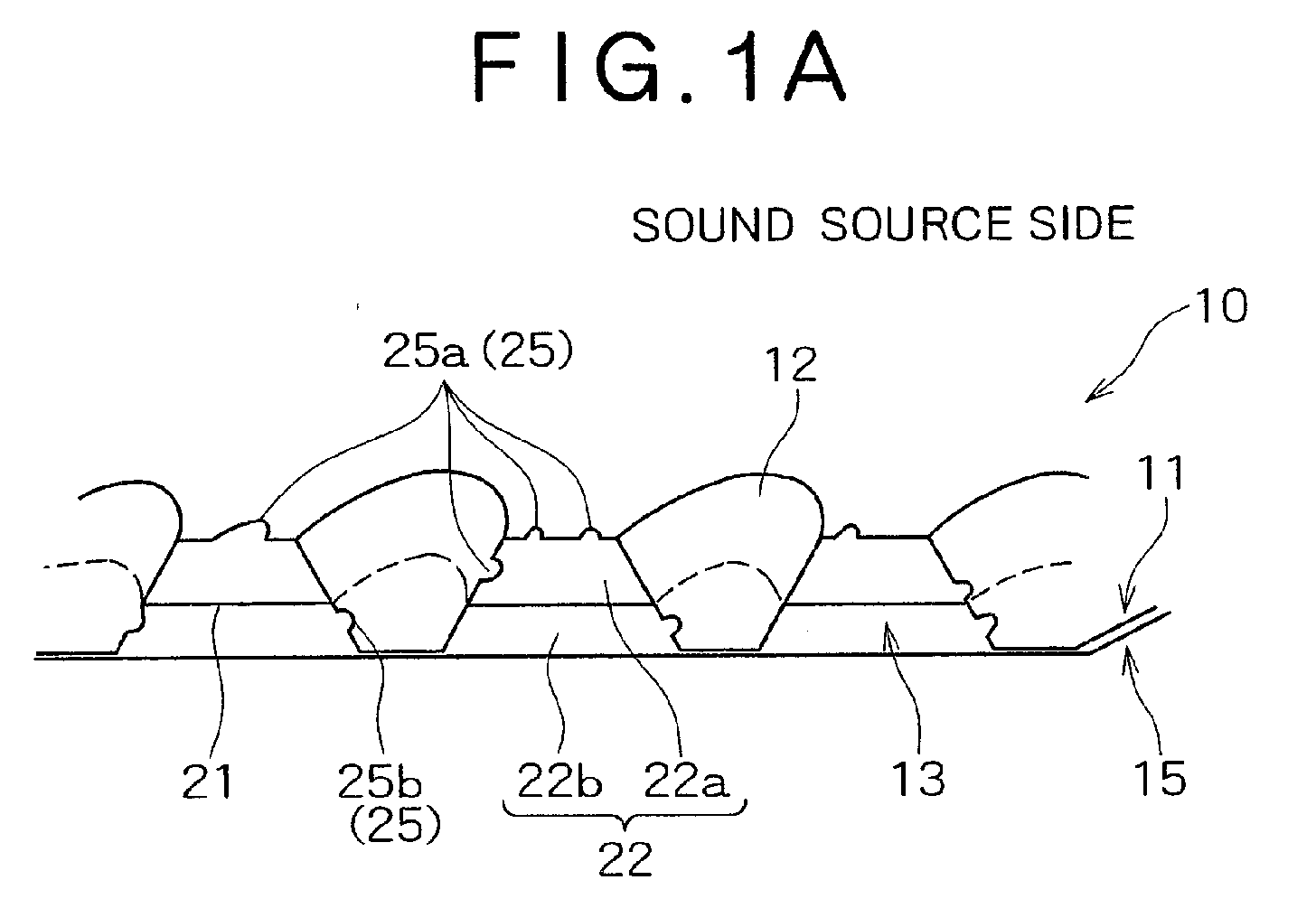
- Figs. 1(a) and 1(b) are explanatory diagrams each showing a schematic configuration of a sound-absorbing structure body according to a first embodiment of the present invention.
- a sound-absorbing structure body 10 is basically constituted by a laminated structure body comprising a ridge-groove board 11 formed with a large number of independent grooves 12 and a closing board 15 which is joined to the ridge-groove board 11 so as to form a hollow portion 13 between adjacent grooves (anti-sound source side of the ridges).
- a partition board 21 for partitioning the hollow portion 13 into two or more partitioned spaces 22 and hole groups 25 which are opened in the ridge-groove board 11 so as to communicate with each of the two or more partitioned spaces 22.
- the ridge-groove board 11 comprises a large number of cone (truncated cone)-shaped grooves 12.
- the grooves 12 may be not only in such a truncated cone shape as shown in the drawing but also for example in a semispherical shape, a rod shape of a semicircular section, or a boat shape. Further, the grooves 12 may be arranged in any various forms, including checkerboard, lattice and zigzag forms.
- the partition board 21 partitions each hollow portion 13 vertically into two stages of a first partitioned space 22a and a second partitioned space 22b.
- the partition board 21 is a perforated board having a large number of holes in which the grooves 12 are closely fitted.
- As the partition board it is preferable to use a metallic board such as an aluminum or iron board which can be joined to the ridge-groove board 11 by spot welding.
- a resin board may be bonded to the ridge-groove board 11.
- the first partitioned space 22a is in communication with an exterior space on the sound source side through a first hole group 25a comprising a large number of holes which are opened to a sound source-side surface of the ridge-groove board 11 and a large number of holes which are opened to side surfaces of the grooves 12.
- the second partitioned space 22b is in communication with the exterior space on the sound source side through a second hole group 25b comprising a large number of holes which are opened to side surfaces of the grooves 12.
- the first partitioned space 22a and the first hole group 25a constitute a first resonance type sound absorber which exhibits a predetermined sound absorption coefficient at a predetermined frequency
- the second partitioned space 22b and the second hole group 25b constitute a second resonance type sound absorber which exhibits a predetermined sound absorption coefficient at a predetermined frequency.
- Two sound absorption peaks can be provided by the first and second sound resonance type absorbers and a required sound absorption coefficient band can be widened by adjusting the two peak frequencies.
- Two partition boards parallel to the closing board 15 may be provided so as to partition space between the ridge-groove board 11 and the closing board 15 into three stages of first, second and third partitioned spaces.
- a required sound absorption coefficient band can be widened by adjusting the three peak frequencies.
- N number of peaks which exhibit a desired sound absorption coefficient at a predetermined frequency can be obtained by forming n number of partitioned spaces as in Fig. 1(b) and by suitably selecting one, or one combination or more, of the number of holes formed in each partitioned space, a diameter thereof, an opening ratio of holes, a thickness of the ridge-groove board, and volume or size of each partitioned space.
- the sound-absorbing structure body 100 is basically constituted by a laminated structure body comprising a ridge-groove board 111 having alternate ridges 112 and grooves and a closing board 115 joined to the bottoms of the grooves so as to form a hollow portion 113 within each of the ridges 112.
- partition boards 121, 131, 141, 142 each for partitioning each hollow portion 113 into two or more partitioned spaces and two or more hole groups 125a, 125b, 135a, 135b, 145a, 145b, 145c which are opened to the surface of the ridge-groove board 111 so as to communicate with two or more partitioned spaces 122a, 122b, 132a, 132b, 143a, 143b, 143c.
- a partition board 121 is disposed obliquely in a diagonal form to partition the hollow portion 113 into two partitioned spaces 122a and 122b of a triangular section, and a first hole group 125a communicating with the partitioned spaces 122a and 122b are formed.
- a partition board 131 perpendicular to the center of the ridge 112 is disposed to partition the hollow portion 113 into left and right partitioned spaces 132a, 132b, and first hole groups 135a and 135b communicating with the partitioned spaces 132a and 132b, respectively, are formed.
- a first partition board 141 parallel to the closing board 115 and a second partition board 142 which is oblique relative to the closing board 115 are disposed to partition the hollow portion 113 into three vertical stages of partitioned spaces 143a, 143b and 143c, and first group holes 145a, 145b and 145c communicating with the partitioned spaces 143a, 143b and 143c, respectively, are formed.
- foils 201a and 201b are added into the partitioned space 22a used in the sound-absorbing structure of the first embodiment.
- a first perforated foil 201a is fitted into the first partitioned space in parallel with the closing board 15, making it possible for the first foil 201a to vibrate or be rubbed with air passing into and out of the first hole group 25a.
- a second perforated foil 201b is fitted into the second partitioned space in parallel with the closing board 15, making it possible for the second foil 201b to vibrate or be rubbed with air passing into and out of the second hole group 25b.
- each of the foils 201a and 201b there may be used a mere foil, foil formed in a ridge-groove shape, foil formed in a folded shape, or foil having plural through holes.
- the foil having plural through holes is advantageous in that not only the configuration is simple but also the sound absorption coefficient of each sound absorption peak frequency further increases with a sound wave passing through the through holes formed in the foil.
- the second foil may be obliquely inserted so as to confront the second hole group 25b.
- one or more sheets of foil can be inserted into one or more partitioned spaces.
- the sound absorption coefficient of each sound absorption peak frequency increases as a result of vibration or rubbing of the foil.
- porous sound-absorbing materials 301a and 301b are added into an interior space of the sound-absorbing structure body of the first embodiment.
- a porous sound-absorbing material 301a is fitted into an upper portion of the first partitioned space 22a and a perforated sound-absorbing material 301b is fitted into a lower portion of the second partitioned space 22b.
- various forms are available, including those shown in the central hollow portion and the right-hand hollow portion in Fig. 4.
- porous sound-absorbing materials 301a and 301b there is used a fibrous sound-absorbing material such as glass wool, a metallic fiber such as aluminum or stainless steel, a compressed product of a paper strip-like metal, non-woven cloth, or a metallic or resinous foam.
- shape of the sound-absorbing materials there may be used any of various shapes, including a plate-like shape.
- the sound source-side surface of the sound-absorbing structure body of the first embodiment is covered with a sound-absorbing material 401.
- a sound-absorbing material there may be used any of various sound-absorbing materials in addition to the porous sound-absorbing materials described above. It is possible to effect sound absorption for high frequencies other than the resonance type sound absorption peak frequency.
- a perforated board 501 is disposed at intervals of a predetermined distance on the sound source-side surface of the sound-absorbing structure of the second embodiment.
- the perforated board 501 brings about a sound absorbing effect of widening the sound absorption frequency band and thereby increasing the sound absorption coefficient.
- a sound-absorbing structure body can be provided wherein a closing board is attached to the bottoms of ridges of a ridge-groove board having a large number of such ridges whose interiors are hollow, the hollow portions are partitioned into two or more partitioned spaces by a partition board, and one or more holes opened in the ridge-groove board are formed so as to communicate with each of the partitioned spaces.
- a closing board is attached to the bottoms of ridges of a ridge-groove board having a large number of such ridges whose interiors are hollow
- the hollow portions are partitioned into two or more partitioned spaces by a partition board
- one or more holes opened in the ridge-groove board are formed so as to communicate with each of the partitioned spaces.
- Simulation was performed with respect to a sound absorption characteristic of a sample of the sound-absorbing structure body shown in Fig. 3, the sample having such various factors as shown in Fig. 9.
- a mere aluminum foil into a hollow portion it is possible to increase the sound absorption coefficient of a sound absorption peak in a high frequency range.
- the sound absorption coefficient of the sound absorption peak in the high frequency range can be further increased.
Landscapes
- Physics & Mathematics (AREA)
- Engineering & Computer Science (AREA)
- Acoustics & Sound (AREA)
- Multimedia (AREA)
- Mechanical Engineering (AREA)
- Soundproofing, Sound Blocking, And Sound Damping (AREA)
- Building Environments (AREA)
Abstract
A sound-absorbing structure body according to the present invention
comprises a ridge-groove board (11) formed with a large number of ridges
and grooves, a closing board (15) joined to the ridge-groove board so as to
close one side of the ridge-groove board and thereby form a hollow portion
(13), a partition board (21) for partitioning the hollow portion (13) into two
or more partitioned spaces (22a, 22b), and two or more holes (25a, 25b)
opened in the ridge-groove board so as to bring into communication with
each of the two or more partitioned spaces (22a, 22b).
Description
The present invention relates to a sound-absorbing structure body
comprising a ridge-groove board formed with a large number of ridges and
grooves and a closing board joined to the ridge-groove board so as to close
one side of the ridge-groove board.
Heretofore, a sound-absorbing member for a vehicle has been known
in which a perforated board is disposed on a lower surface side of a panel
through an air layer and a thickness of the perforated board, a diameter and
a pitch of holes and a thickness of the air layer are adjusted to absorb noises
in a predetermined frequency range.
Noises in a specific frequency range are effectively absorbed by
adjusting the thickness of the perforated board, the diameter and pitch of
holes and the thickness of the air layer and by utilizing the Helmholtz's
resonance principle.
Since the above conventional technique uses a resonance type
sound-absorbing mechanism, there is only one peak frequency and it is
difficult to provide two or more peak frequencies.
It is an object of the present invention to provide a sound-absorbing
structure body capable of expanding a sound absorption frequency band.
More specifically, according to the present invention there is
provided a sound-absorbing structure body comprising a ridge-groove board
formed with a large number of ridges and grooves, a closing board joined to
the ridge-groove board so as to close one side of the ridge-groove board and
thereby form a hollow portion, a partition board for partitioning the hollow
portion into two or more partitioned spaces, and one or more holes opened in
the ridge-groove board so as to bring each of the two or more partitioned
spaces into communication with an exterior space.
By partitioning the hollow portion into two or more partitioned
spaces and forming one or more holes through which each partitioned space
communicates with an exterior space in the ridge-groove board, each
partitioned space comes to function as a resonance type sound-absorbing
mechanism, whereby it is possible to produce a peak frequency with a sound
absorption coefficient corresponding to each partitioned space.
For each of the partitioned spaces, by changing the number and
diameter of holes and the opening ratio of holes to the ridge-groove board
corresponding to the partitioned space, a peak frequency with a sound
absorption coefficient corresponding to each partitioned space can be
produced. Furthermore, as to the partitioned spaces, partitioning may be
done in various forms each having a predetermined internal volume, for
example, by disposing horizontally, vertically or obliquely the partition
board for partitioning the hollow portion into two or more partitioned spaces.
Preferably, one or more foils are disposed in at least one of two or
more partitioned spaces so that the foil(s) can vibrate or can be rubbed.
A sound wave which has reached a partitioned space causes
vibration or rubbing of the foil(s) and the sound absorption coefficient of
each sound absorption peak frequency increases due to viscosity induced
when the sound wave passes between the foils. The foils may be disposed
respectively into two or more partitioned spaces or the foil may be disposed
selectively into a partitioned space having a predetermined sound
absorption peak frequency.
Preferably, the foil(s) has plural through holes.
If the foil(s) has plural through holes, the sound absorption
coefficient of each sound-absorbing peak frequency further increases.
Preferably, a porous sound-absorbing material is disposed in at least
one of two or more partitioned spaces.
If the porous sound-absorbing material is disposed in the interior of
a partitioned space which communicates with an outside air through at
least one hole, the sound absorption coefficient of each sound absorption
peak frequency increases due to damping of the sound wave caused by the
porous sound-absorbing material.
Preferably, the other side of the ridge-groove board is covered with
the sound-absorbing material.
The sound-absorbing material on the surface absorbs a high
frequency in addition to the peak frequency in the resonance type sound
absorption based on hole groups in each partitioned space.
Preferably, a perforated board is disposed on the other side of the
ridge-groove board.
Due to a sound absorbing effect attained by the perforated board,
the sound absorption frequency band is widened and the sound absorption
coefficient near the sound absorption peak frequency is increased.
Figs. 1(a) and 1(b) are explanatory diagrams each showing a
schematic configuration of a sound-absorbing structure body according to a
first embodiment of the present invention.
In Fig. 1(a), a sound-absorbing structure body 10 is basically
constituted by a laminated structure body comprising a ridge-groove board
11 formed with a large number of independent grooves 12 and a closing
board 15 which is joined to the ridge-groove board 11 so as to form a hollow
portion 13 between adjacent grooves (anti-sound source side of the ridges).
In the laminated structure body are provided a partition board 21
for partitioning the hollow portion 13 into two or more partitioned spaces 22
and hole groups 25 which are opened in the ridge-groove board 11 so as to
communicate with each of the two or more partitioned spaces 22.
The ridge-groove board 11 comprises a large number of cone
(truncated cone)-shaped grooves 12. The grooves 12 may be not only in
such a truncated cone shape as shown in the drawing but also for example
in a semispherical shape, a rod shape of a semicircular section, or a boat
shape. Further, the grooves 12 may be arranged in any various forms,
including checkerboard, lattice and zigzag forms.
By superimposing the closing board 15 which is flat onto the back
sides of the bottoms of the grooves 12, there are formed hollow portions 13
spreading around the grooves 12. With the closing board 15 disposed on
the back sides of the grooves 12, it is possible to form intercommunicating
wide hollow portions 13 around the grooves 12. Surroundings of the
laminated structure body comprising the ridge-groove board 11 and the
closing board 15 are closed by suitable means. For forming the grooves 12,
a metallic board such as an aluminum or iron board is used as the ridge-groove
board 11. As the closing board 15 there used, for example, a
metallic board such as an aluminum or iron board or a resin or wooden
board. Suitable connecting means, e.g., bonding, welding, or screwing, is
adopted for connection of the closing board 15 to the bottoms of the grooves
12 in the ridge-groove board 11.
It is the partition board 21 that partitions each hollow portion 13
vertically into two stages of a first partitioned space 22a and a second
partitioned space 22b. The partition board 21 is a perforated board having
a large number of holes in which the grooves 12 are closely fitted.
As the partition board, it is preferable to use a metallic board such as an
aluminum or iron board which can be joined to the ridge-groove board 11 by
spot welding. However, a resin board may be bonded to the ridge-groove
board 11.
The first partitioned space 22a is in communication with an exterior
space on the sound source side through a first hole group 25a comprising a
large number of holes which are opened to a sound source-side surface of the
ridge-groove board 11 and a large number of holes which are opened to side
surfaces of the grooves 12. The second partitioned space 22b is in
communication with the exterior space on the sound source side through a
second hole group 25b comprising a large number of holes which are opened
to side surfaces of the grooves 12.
The first partitioned space 22a and the first hole group 25a
constitute a first resonance type sound absorber which exhibits a
predetermined sound absorption coefficient at a predetermined frequency,
while the second partitioned space 22b and the second hole group 25b
constitute a second resonance type sound absorber which exhibits a
predetermined sound absorption coefficient at a predetermined frequency.
Two sound absorption peaks can be provided by the first and second sound
resonance type absorbers and a required sound absorption coefficient band
can be widened by adjusting the two peak frequencies.
Two partition boards parallel to the closing board 15 may be
provided so as to partition space between the ridge-groove board 11 and the
closing board 15 into three stages of first, second and third partitioned
spaces. In this case, there are formed first, second and third hole groups
corresponding to the first, second and third partitioned spaces, respectively,
whereby three sound absorption peaks can be provided. Thus, a required
sound absorption coefficient band can be widened by adjusting the three
peak frequencies.
N number of peaks which exhibit a desired sound absorption
coefficient at a predetermined frequency can be obtained by forming n
number of partitioned spaces as in Fig. 1(b) and by suitably selecting one, or
one combination or more, of the number of holes formed in each partitioned
space, a diameter thereof, an opening ratio of holes, a thickness of the ridge-groove
board, and volume or size of each partitioned space.
According to the first embodiment, as described above, there is
attained an effect that plural sound absorption peaks can be provided
despite the laminated structure body comprising the ridge-groove board 11
and the closing board 15.
Next, a sound-absorbing structure 100 according to a second
embodiment of the present invention will be described below with reference
to Fig. 2.
The sound-absorbing structure body 100 is basically constituted by a
laminated structure body comprising a ridge-groove board 111 having
alternate ridges 112 and grooves and a closing board 115 joined to the
bottoms of the grooves so as to form a hollow portion 113 within each of the
ridges 112. In this laminated structure body there are provided partition
boards 121, 131, 141, 142 each for partitioning each hollow portion 113 into
two or more partitioned spaces and two or more hole groups 125a, 125b,
135a, 135b, 145a, 145b, 145c which are opened to the surface of the ridge-groove
board 111 so as to communicate with two or more partitioned spaces
122a, 122b, 132a, 132b, 143a, 143b, 143c.
In the left ridge 112 shown in Fig. 2, a partition board 121 is
disposed obliquely in a diagonal form to partition the hollow portion 113 into
two partitioned spaces 122a and 122b of a triangular section, and a first
hole group 125a communicating with the partitioned spaces 122a and 122b
are formed.
In the central ridge 112 shown in Fig. 2, a partition board 131
perpendicular to the center of the ridge 112 is disposed to partition the
hollow portion 113 into left and right partitioned spaces 132a, 132b, and
first hole groups 135a and 135b communicating with the partitioned spaces
132a and 132b, respectively, are formed.
In the right ridge 112 shown in Fig. 2, a first partition board 141
parallel to the closing board 115 and a second partition board 142 which is
oblique relative to the closing board 115 are disposed to partition the hollow
portion 113 into three vertical stages of partitioned spaces 143a, 143b and
143c, and first group holes 145a, 145b and 145c communicating with the
partitioned spaces 143a, 143b and 143c, respectively, are formed.
Although in Fig. 2 the hollow portions 113 in the three ridges 112
are partitioned in three different forms, there may be adopted any one of
those partitioning forms.
As the number of partitioning forms increases, it becomes possible to shift the sound absorption peak frequency accordingly.
As the number of partitioning forms increases, it becomes possible to shift the sound absorption peak frequency accordingly.
Next, a sound-absorbing structure body 200 according to a third
embodiment of the present invention will be described below.
In the sound-absorbing structure body 200, foils 201a and 201b are
added into the partitioned space 22a used in the sound-absorbing structure
of the first embodiment. As shown in the left-hand hollow portion in Fig. 3,
a first perforated foil 201a is fitted into the first partitioned space in parallel
with the closing board 15, making it possible for the first foil 201a to vibrate
or be rubbed with air passing into and out of the first hole group 25a. Into
the second partitioned space is fitted a second perforated foil 201b in
parallel with the closing board 15, making it possible for the second foil 201b
to vibrate or be rubbed with air passing into and out of the second hole
group 25b.
As each of the foils 201a and 201b, there may be used a mere foil,
foil formed in a ridge-groove shape, foil formed in a folded shape, or foil
having plural through holes. Particularly, the foil having plural through
holes is advantageous in that not only the configuration is simple but also
the sound absorption coefficient of each sound absorption peak frequency
further increases with a sound wave passing through the through holes
formed in the foil.
As shown in the central hollow portion in Fig. 3, the second foil may
be obliquely inserted so as to confront the second hole group 25b. Thus, in
various forms one or more sheets of foil can be inserted into one or more
partitioned spaces. The sound absorption coefficient of each sound
absorption peak frequency increases as a result of vibration or rubbing of
the foil.
Next, a sound-absorbing structure body 300 according to a fourth
embodiment of the present invention will be described below.
In the sound-absorbing structure body 300, porous sound-absorbing
materials 301a and 301b are added into an interior space of the sound-absorbing
structure body of the first embodiment. As shown in the left-hand
hollow portion in Fig. 4, a porous sound-absorbing material 301a is
fitted into an upper portion of the first partitioned space 22a and a
perforated sound-absorbing material 301b is fitted into a lower portion of
the second partitioned space 22b. As to in what form the porous sound-absorbing
materials are to be fitted into the partitioned spaces, various
forms are available, including those shown in the central hollow portion and
the right-hand hollow portion in Fig. 4. As the porous sound-absorbing
materials 301a and 301b, there is used a fibrous sound-absorbing material
such as glass wool, a metallic fiber such as aluminum or stainless steel, a
compressed product of a paper strip-like metal, non-woven cloth, or a
metallic or resinous foam. As to the shape of the sound-absorbing
materials, there may be used any of various shapes, including a plate-like
shape. With the sound-absorbing materials 301a and 301b inserted into a
partitioned space, the sound absorption coefficient of a sound absorption
peak frequency increases as a result of damping of a sound wave by the
sound-absorbing materials.
Next, a sound-absorbing structure body 400 according to a fifth
embodiment of the present invention will be described below.
In the sound-absorbing structure body 400, the sound source-side
surface of the sound-absorbing structure body of the first embodiment is
covered with a sound-absorbing material 401. As the sound-absorbing
material, there may be used any of various sound-absorbing materials in
addition to the porous sound-absorbing materials described above.
It is possible to effect sound absorption for high frequencies other than the resonance type sound absorption peak frequency.
It is possible to effect sound absorption for high frequencies other than the resonance type sound absorption peak frequency.
Next, a sound-absorbing structure body 500 according to a sixth
embodiment of the present invention will be described below.
In the sound-absorbing structure body 500, a perforated board 501 is
disposed at intervals of a predetermined distance on the sound source-side
surface of the sound-absorbing structure of the second embodiment. The
perforated board 501 brings about a sound absorbing effect of widening the
sound absorption frequency band and thereby increasing the sound
absorption coefficient.
The present invention is described in the above preferred
embodiments, but is not limited thereto. It will be understood that various
other embodiments not departing from the spirit and scope of the present
invention can be adopted.
For example, a sound-absorbing structure body can be provided
wherein a closing board is attached to the bottoms of ridges of a ridge-groove
board having a large number of such ridges whose interiors are hollow, the
hollow portions are partitioned into two or more partitioned spaces by a
partition board, and one or more holes opened in the ridge-groove board are
formed so as to communicate with each of the partitioned spaces. In this
case, it is possible to form a large number of independent hollow portions
within the ridges and to partition each of the hollow portions into various
forms.
Simulation was performed with respect to a sound absorption
characteristic of a sample of the sound-absorbing structure body shown in
Fig. 1, the sample having such various factors as shown in Fig. 7, results of
which are shown in Fig. 8. In case of dividing a hollow portion in two, a
large sound absorption peak can be developed in a low frequency range as
compared with the case where the hollow portion is not divided.
Simulation was performed with respect to a sound absorption
characteristic of a sample of the sound-absorbing structure body shown in
Fig. 3, the sample having such various factors as shown in Fig. 9. In case
of inserting a mere aluminum foil into a hollow portion, it is possible to
increase the sound absorption coefficient of a sound absorption peak in a
high frequency range. In case of inserting an aluminum foil having a large
number of through holes into a hollow portion, the sound absorption
coefficient of the sound absorption peak in the high frequency range can be
further increased.
Claims (6)
- A sound-absorbing structure body comprising a ridge-groove board formed with a large number of ridges and grooves, a closing board joined to said ridge-groove board so as to close one side of said ridge-groove board and thereby form a hollow portion, a partition board for partitioning said hollow portion into two or more partitioned spaces, and one or more holes opened in said ridge-groove board so as to bring each of said two or more partitioned spaces into communication with an exterior space.
- The sound-absorbing structure body according to claim 1, wherein one or more foils are disposed in at least one of said two or more partitioned spaces so that the foil(s) can vibrate or can be rubbed.
- The sound-absorbing structure body according to claim 2, wherein said foil(s) has (have) a plurality of through holes.
- The sound-absorbing structure body according to claim 1, wherein a porous sound-absorbing material is disposed in at least one of said two or more partitioned spaces.
- The sound-absorbing structure body according to claim 1, wherein the other side of said ridge-groove board is covered with a sound-absorbing material.
- The sound-absorbing structure body according to claim 1, wherein a perforated board is disposed on the other side of said ridge-groove board.
Applications Claiming Priority (3)
| Application Number | Priority Date | Filing Date | Title |
|---|---|---|---|
| JP2003045483A JP4050632B2 (en) | 2003-02-24 | 2003-02-24 | Sound absorbing structure |
| JP2003045483 | 2003-02-24 | ||
| PCT/JP2004/000598 WO2004075164A1 (en) | 2003-02-24 | 2004-01-23 | Sound-absorbing structure body |
Publications (2)
| Publication Number | Publication Date |
|---|---|
| EP1598809A1 true EP1598809A1 (en) | 2005-11-23 |
| EP1598809A4 EP1598809A4 (en) | 2008-06-04 |
Family
ID=32905525
Family Applications (1)
| Application Number | Title | Priority Date | Filing Date |
|---|---|---|---|
| EP04704725A Withdrawn EP1598809A4 (en) | 2003-02-24 | 2004-01-23 | Sound-absorbing structure body |
Country Status (6)
| Country | Link |
|---|---|
| US (1) | US20060131104A1 (en) |
| EP (1) | EP1598809A4 (en) |
| JP (1) | JP4050632B2 (en) |
| KR (1) | KR100720639B1 (en) |
| CN (1) | CN1754202A (en) |
| WO (1) | WO2004075164A1 (en) |
Families Citing this family (20)
| Publication number | Priority date | Publication date | Assignee | Title |
|---|---|---|---|---|
| KR101274509B1 (en) * | 2006-04-27 | 2013-06-13 | 마사오 스즈키 | Sound insulating device |
| JP4981880B2 (en) * | 2009-11-30 | 2012-07-25 | 株式会社神戸製鋼所 | Soundproofing material and soundproofing system |
| JP5986313B2 (en) * | 2012-07-06 | 2016-09-06 | シーアンドディー ゾディアック,インコーポレイティド | Aircraft interior panel with acoustic material |
| JP5918662B2 (en) * | 2012-09-04 | 2016-05-18 | 株式会社神戸製鋼所 | Porous sound absorbing structure |
| JP6165466B2 (en) * | 2013-02-27 | 2017-07-19 | 株式会社神戸製鋼所 | Soundproof structure |
| FR3018384B1 (en) * | 2014-03-04 | 2016-03-11 | Scherrer Jean Marc | ACOUSTIC ABSORPTION ASSEMBLY WITH HIGH AND LOW FREQUENCIES |
| JP6421062B2 (en) * | 2015-03-20 | 2018-11-07 | 克己 櫂谷 | Thin plate-like sound absorbing structure and its manufacturing method |
| JP6352336B2 (en) * | 2015-11-27 | 2018-07-04 | 株式会社神戸製鋼所 | Porous sound absorbing plate |
| JP2017151256A (en) * | 2016-02-24 | 2017-08-31 | 宇部エクシモ株式会社 | Hollow structure plate, and sound absorption structure |
| CN106836538A (en) * | 2016-12-30 | 2017-06-13 | 常熟南师大发展研究院有限公司 | One kind building abatvoix |
| KR101973022B1 (en) * | 2017-09-13 | 2019-04-26 | 한국기계연구원 | Sound absorbing cell and sound absorbing structure having the same |
| WO2019069908A1 (en) * | 2017-10-03 | 2019-04-11 | 富士フイルム株式会社 | Muffled tubular structure |
| CN111213201B (en) * | 2017-10-11 | 2024-03-05 | 富士胶片株式会社 | Box sound insulation structure and transportation equipment |
| JP7017132B2 (en) * | 2018-09-25 | 2022-02-08 | トヨタ車体株式会社 | Manufacturing method of sound absorbing and insulating member |
| TWI669430B (en) * | 2018-10-31 | 2019-08-21 | 許翃銘 | Sound-absorbing panels |
| JP7132161B2 (en) * | 2019-03-20 | 2022-09-06 | トヨタ自動車株式会社 | Locker exterior structure |
| CN111186188B (en) * | 2020-01-19 | 2021-04-27 | 东风汽车集团有限公司 | A sound-absorbing and heat-insulating pad for automobile engine compartment |
| US11776522B2 (en) * | 2020-11-12 | 2023-10-03 | Toyota Motor Engineering & Manufacturing North America, Inc. | Sound isolating wall assembly having at least one acoustic scatterer |
| KR102713331B1 (en) * | 2022-12-29 | 2024-10-11 | 주식회사 젠픽스 | Ceiling board applying indoor noise reduction structure |
| CN116863902A (en) * | 2023-08-16 | 2023-10-10 | 上海材料研究所有限公司 | A multi-cavity acoustic metamaterial with a Y-shaped plug-in assembly structure |
Family Cites Families (43)
| Publication number | Priority date | Publication date | Assignee | Title |
|---|---|---|---|---|
| GB946007A (en) * | 1960-12-23 | 1964-01-08 | Gomma Antivibranti Applic | Improvements relating to walls or ceilings having a sound absorbing covering |
| US3232372A (en) * | 1963-07-30 | 1966-02-01 | Gomma Antivibranti Applic | Sound-absorbing covering |
| US3269484A (en) * | 1963-09-24 | 1966-08-30 | Lighter Stephen | Acoustic absorbing structure |
| US4130175A (en) * | 1977-03-21 | 1978-12-19 | General Electric Company | Fluid-impervious acoustic suppression panel |
| SE420750B (en) * | 1978-11-17 | 1981-10-26 | Ingemanssons Ingenjorsbyra Ab | SOUND-INSULATING BUILDING ELEMENT WITH GREAT STUFF |
| SE424654B (en) * | 1979-05-11 | 1982-08-02 | Ifm Akustikbyran Ab | hygienic absorbent |
| JPS5792240A (en) * | 1980-11-29 | 1982-06-08 | Matsushita Electric Works Ltd | Sound isolated panel |
| DE3233654C2 (en) * | 1982-09-10 | 1986-01-16 | Ewald Dörken AG, 5804 Herdecke | Sound-absorbing component |
| US4562901A (en) * | 1983-10-12 | 1986-01-07 | Miguel C. Junger | Sound absorptive structural block with sequenced cavities |
| CH678201A5 (en) * | 1989-03-17 | 1991-08-15 | Lignoform Formsperrholz Ag | |
| US5180619A (en) * | 1989-12-04 | 1993-01-19 | Supracor Systems, Inc. | Perforated honeycomb |
| US5124191A (en) * | 1991-03-11 | 1992-06-23 | Aluminum Company Of America | Structural panel |
| US5241512A (en) * | 1991-04-25 | 1993-08-31 | Hutchinson 2 | Acoustic protection material and apparatus including such material |
| JPH05280122A (en) * | 1992-02-21 | 1993-10-26 | Matsushita Electric Ind Co Ltd | Acoustic reflector |
| JPH05232967A (en) * | 1992-02-21 | 1993-09-10 | Matsushita Electric Ind Co Ltd | Sound absorber |
| US5244745A (en) * | 1992-04-16 | 1993-09-14 | Aluminum Company Of America | Structural sheet and panel |
| JPH06158751A (en) * | 1992-11-25 | 1994-06-07 | Matsushita Electric Ind Co Ltd | Acoustic absorber |
| DE4408782A1 (en) * | 1994-03-15 | 1995-09-21 | Fraunhofer Ges Forschung | Foil sound absorber |
| JP3440247B2 (en) * | 1994-08-12 | 2003-08-25 | カーコースティックス テック センター ゲーエムベーハー | Sound absorbing device |
| DE9414943U1 (en) * | 1994-09-14 | 1996-01-18 | M. Faist GmbH & Co KG, 86381 Krumbach | Foil resonance absorber |
| JPH08310314A (en) * | 1995-05-15 | 1996-11-26 | Toyoda Gosei Co Ltd | Soundproof material |
| JP3306610B2 (en) * | 1994-12-13 | 2002-07-24 | エヌ・オー・ケー・ビブラコースティック株式会社 | Manufacturing method of sound absorbing material |
| JPH08207833A (en) * | 1995-02-07 | 1996-08-13 | Yamakawa Ind Co Ltd | Automotive engine undercover with sound absorption function |
| JP2762956B2 (en) * | 1995-05-17 | 1998-06-11 | 日産自動車株式会社 | Sound insulation wall structure |
| DE29617845U1 (en) * | 1996-10-14 | 1998-02-12 | M. Faist GmbH & Co. KG, 86381 Krumbach | Device for absorbing and / or damping sound waves |
| DE19652527A1 (en) * | 1996-12-17 | 1998-06-18 | Faist M Gmbh & Co Kg | Absorber for absorbing acoustic sound waves |
| JPH10333686A (en) * | 1997-05-28 | 1998-12-18 | Sharp Corp | Silencer |
| FR2775216B1 (en) * | 1998-02-26 | 2000-07-13 | Snecma | SOUNDPROOFING PANEL AND METHOD FOR PRODUCING THE SAME |
| DE19910595A1 (en) * | 1999-03-10 | 2000-09-21 | Volkswagen Ag | Airborne sound-absorbing molded part |
| JP3536201B2 (en) * | 1999-04-22 | 2004-06-07 | 株式会社アルム | Sound absorbing panel |
| US6125965A (en) * | 1999-10-04 | 2000-10-03 | Wang; Chao-Shun | Acoustic board |
| DE10002984C1 (en) * | 2000-01-24 | 2001-08-09 | Daimler Chrysler Ag | Acoustic absorber and method for sound absorption |
| FR2815900B1 (en) * | 2000-10-31 | 2003-07-18 | Eads Airbus Sa | NOISE REDUCING SANDWICH PANEL, ESPECIALLY FOR AN AIRCRAFT TURBOREACTOR |
| EP1408483A4 (en) * | 2001-06-21 | 2008-06-11 | Kobe Steel Ltd | Porous soundproof structural body and method of manufacturing the structural body |
| DE10322168B4 (en) * | 2002-05-16 | 2008-12-18 | Toyoda Gosei Co., Ltd. | Air intake device |
| JP2004062074A (en) * | 2002-07-31 | 2004-02-26 | Toyota Motor Corp | Sound absorbing device |
| FR2862798B1 (en) * | 2003-11-21 | 2006-03-17 | Snecma Moteurs | INSONORIZING BALL PANEL AND METHOD OF MAKING SAME |
| DE20320100U1 (en) * | 2003-12-23 | 2005-05-12 | Carcoustics Tech Center Gmbh | Airborne sound absorbing component |
| US7267196B2 (en) * | 2004-02-12 | 2007-09-11 | The Boeing Company | Method and apparatus for reducing acoustic noise |
| US20050205354A1 (en) * | 2004-03-19 | 2005-09-22 | Visteon Global Technologies, Inc. | Dual chamber variable geometry resonator |
| US7089901B2 (en) * | 2004-03-30 | 2006-08-15 | Toyoda Gosei Co., Ltd. | Resonator |
| EP1742201A4 (en) * | 2004-04-30 | 2017-07-19 | Kabushiki Kaisha Kobe Seiko Sho | Porous sound absorbing structure |
| JP2006125381A (en) * | 2004-09-29 | 2006-05-18 | Toyoda Gosei Co Ltd | Resonator |
-
2003
- 2003-02-24 JP JP2003045483A patent/JP4050632B2/en not_active Expired - Fee Related
-
2004
- 2004-01-23 WO PCT/JP2004/000598 patent/WO2004075164A1/en not_active Ceased
- 2004-01-23 US US10/545,161 patent/US20060131104A1/en not_active Abandoned
- 2004-01-23 KR KR1020057015536A patent/KR100720639B1/en not_active Expired - Fee Related
- 2004-01-23 EP EP04704725A patent/EP1598809A4/en not_active Withdrawn
- 2004-01-23 CN CNA200480005040XA patent/CN1754202A/en active Pending
Also Published As
| Publication number | Publication date |
|---|---|
| US20060131104A1 (en) | 2006-06-22 |
| JP2004264372A (en) | 2004-09-24 |
| JP4050632B2 (en) | 2008-02-20 |
| KR20050106027A (en) | 2005-11-08 |
| EP1598809A4 (en) | 2008-06-04 |
| WO2004075164A1 (en) | 2004-09-02 |
| KR100720639B1 (en) | 2007-05-21 |
| CN1754202A (en) | 2006-03-29 |
Similar Documents
| Publication | Publication Date | Title |
|---|---|---|
| EP1598809A1 (en) | Sound-absorbing structure body | |
| KR100787297B1 (en) | Sound absorbing structure and method of producing the same | |
| US5633067A (en) | Engine compartment casing element with perforated foam layer | |
| US20050263346A1 (en) | Sound-absorbing structure and sound-absorbing unit | |
| Kronowetter et al. | Novel compound material and metamaterial wheelhouse liners for tire noise reduction | |
| US5410111A (en) | Housing lining | |
| JP2007502748A (en) | Noise reduction components such as vehicle floor panels | |
| JP4291760B2 (en) | Sound absorbing structure and manufacturing method thereof | |
| US20080135332A1 (en) | Double Wall Structure | |
| WO2018189879A1 (en) | Railway vehicle | |
| JPH09228506A (en) | Sound absorbing material | |
| PL181066B1 (en) | Multi layered sound absorbing structural component | |
| CN212613129U (en) | Sound absorption and insulation board | |
| AU2010233057A1 (en) | An acoustic panel and a method of manufacturing acoustic panels | |
| RU2042547C1 (en) | Vehicle cab noise-absorbing inner panel | |
| RU2052604C1 (en) | Sound absorbing panel | |
| JP2018177042A (en) | Sound absorption panel | |
| JP6958830B2 (en) | Composite sound absorbing material | |
| JP2008015111A (en) | Internal structure of fixed sound absorbing structure and fixed sound absorbing structure | |
| JP4926350B2 (en) | Soundproof surface member | |
| JP2002175083A (en) | Porous soundproof structure | |
| KR20200004039A (en) | Micro-hole noise absorbing plate using trigonal prism shape press die and multi-layered micro-hole noise absorbing apparatus comprising the same | |
| JP2005017635A (en) | Sound absorbing structure | |
| GB2418641A (en) | Automobile interior trim sound absorbing components | |
| CN215170038U (en) | A road tunnel segment with sound absorption function |
Legal Events
| Date | Code | Title | Description |
|---|---|---|---|
| PUAI | Public reference made under article 153(3) epc to a published international application that has entered the european phase |
Free format text: ORIGINAL CODE: 0009012 |
|
| 17P | Request for examination filed |
Effective date: 20050822 |
|
| AK | Designated contracting states |
Kind code of ref document: A1 Designated state(s): AT BE BG CH CY CZ DE DK EE ES FI FR GB GR HU IE IT LI LU MC NL PT RO SE SI SK TR |
|
| AX | Request for extension of the european patent |
Extension state: AL LT LV MK |
|
| DAX | Request for extension of the european patent (deleted) | ||
| A4 | Supplementary search report drawn up and despatched |
Effective date: 20080508 |
|
| 17Q | First examination report despatched |
Effective date: 20101118 |
|
| STAA | Information on the status of an ep patent application or granted ep patent |
Free format text: STATUS: THE APPLICATION IS DEEMED TO BE WITHDRAWN |
|
| 18D | Application deemed to be withdrawn |
Effective date: 20110329 |