EP1598712A1 - Method and device for controlling the biological process in waste-water treatment plants - Google Patents
Method and device for controlling the biological process in waste-water treatment plants Download PDFInfo
- Publication number
- EP1598712A1 EP1598712A1 EP05010111A EP05010111A EP1598712A1 EP 1598712 A1 EP1598712 A1 EP 1598712A1 EP 05010111 A EP05010111 A EP 05010111A EP 05010111 A EP05010111 A EP 05010111A EP 1598712 A1 EP1598712 A1 EP 1598712A1
- Authority
- EP
- European Patent Office
- Prior art keywords
- concentration
- dissolved oxygen
- waste waters
- set point
- membership functions
- Prior art date
- Legal status (The legal status is an assumption and is not a legal conclusion. Google has not performed a legal analysis and makes no representation as to the accuracy of the status listed.)
- Granted
Links
Images
Classifications
-
- G—PHYSICS
- G05—CONTROLLING; REGULATING
- G05B—CONTROL OR REGULATING SYSTEMS IN GENERAL; FUNCTIONAL ELEMENTS OF SUCH SYSTEMS; MONITORING OR TESTING ARRANGEMENTS FOR SUCH SYSTEMS OR ELEMENTS
- G05B13/00—Adaptive control systems, i.e. systems automatically adjusting themselves to have a performance which is optimum according to some preassigned criterion
- G05B13/02—Adaptive control systems, i.e. systems automatically adjusting themselves to have a performance which is optimum according to some preassigned criterion electric
- G05B13/0265—Adaptive control systems, i.e. systems automatically adjusting themselves to have a performance which is optimum according to some preassigned criterion electric the criterion being a learning criterion
- G05B13/0275—Adaptive control systems, i.e. systems automatically adjusting themselves to have a performance which is optimum according to some preassigned criterion electric the criterion being a learning criterion using fuzzy logic only
-
- C—CHEMISTRY; METALLURGY
- C02—TREATMENT OF WATER, WASTE WATER, SEWAGE, OR SLUDGE
- C02F—TREATMENT OF WATER, WASTE WATER, SEWAGE, OR SLUDGE
- C02F2209/00—Controlling or monitoring parameters in water treatment
- C02F2209/22—O2
-
- C—CHEMISTRY; METALLURGY
- C02—TREATMENT OF WATER, WASTE WATER, SEWAGE, OR SLUDGE
- C02F—TREATMENT OF WATER, WASTE WATER, SEWAGE, OR SLUDGE
- C02F3/00—Biological treatment of water, waste water, or sewage
Definitions
- the present invention relates in general to management of the biological process in waste water purifying plants and, in particular, a method and a device for continuous controlling the supply of oxygen in waste waters flowing in an oxidation tank.
- waste water purifying plants the main phase of treatment is represented by the biological process.
- the waste waters are made to flow in a large tank (several hundreds or thousands of cubic meters) containing a specific quantity of micro-organisms (bacteria, protozoa, etc.) which perform degradation of pollutants.
- the principal phase of the biological treatment is aerobic, and it is consequently necessary to maintain a correct concentration of oxygen in the waste water in order to guarantee optimal operating conditions for the micro-organisms.
- This is obtained by supplying oxygen continuously (oxygen can be supplied by blowing air, blowing pure oxygen, remixing the sewage, etc.) to the waste water present inside the tank.
- oxygen can be supplied by blowing air, blowing pure oxygen, remixing the sewage, etc.
- This supply must be delivered in a particularly homogeneous way and in sufficient quantity to allow correct implementation of the purifying process.
- the supply of oxygen has a considerable influence on various aspects of the treatment, such as the removal of nitrogen, the sedimentation of sludge, and the formation and/or growth of filamentous micro-organisms.
- the cost of energy for supplying oxygen through blown air is one of the major cost items in the management of a waste water purifying plant.
- regulation of the air fed to the biological treatment tank is generally based on detection of the concentration of dissolved oxygen (DO) in the waste water present in the treatment tank.
- DO dissolved oxygen
- the control system used consequently acts directly on the compressors (or machinery used to blow air) or on appropriate devices (such as valves) in order to vary or interrupt the air flow.
- one of the limits of PID controllers in this type of application depends on the process conditions, in which there are considerable variations in both the short and the long term and which have particular influence on the concentration of dissolved oxygen. Moreover, in particular conditions, there can be very wide fluctuations with respect to the set point.
- the efficiency of the biological process is compromised under various aspects. Firstly, the differences between the effective amount of oxygen required and the amount provided instantly are in any case counter-productive. In fact, if too little oxygen is supplied, the aerobic process is slowed down, while an excessive concentration of dissolved oxygen can, for example, have a negative influence on the efficiency of the denitrification process. Secondly, high fluctuations with respect to the pre-established set point make the purifying process instable due to the continuous and rapid variations in the concentration of dissolved oxygen to which the biomass is subjected.
- a particularly important aspect is represented by the waste of energy which occurs when the quantity of blown air is greater than the effective requirement. This aspect becomes more important if we consider the usual practice of maintaining high set points with regard to the concentration of dissolved oxygen, i.e., values suitable only when operating in the worst operating conditions, as it is in any case deemed that an excess supply of air is safer than a shortage in supply.
- the general object of the present invention is to propose a method and a device which allow optimization of the supply of air to the aerobic treatment process for waste waters in a purifying plant.
- a specific object of the present invention is to reduce treatment costs correlated principally to the supply of oxygen through blowing air, preventing, above all, an excess supply.
- Another specific object of the present invention is to guarantee process stability, notwithstanding the variability of the characteristics and of the parameters which influence the treatment.
- a further specific object of the present invention is to maintain adequate treatment efficiency at all times.
- the present invention relates to a method for continuously controlling the aerobic biological treatment of waste waters in a purifying plant, wherein the waste waters flowing continuously in an oxidation tank are subjected to aeration through the blowing of pressurized air.
- the method is characterized in that the flow rate of air blown into the waste water is substantially continuously regulated by at least a first control level, which substantially continuously modifies the set point of the concentration of dissolved oxygen in the waste waters.
- the first control level modifies the set point of the concentration of dissolved oxygen in the waste waters as a function of at least the value of concentration of ammonia nitrogen detected in the waste waters and of at least a desired value for the concentration of ammonia nitrogen.
- Calculation of a new set point for the concentration of dissolved oxygen is implemented very frequently with respect to the dynamics of the processes in play, for example, at least every 10-20 minutes, so as to guarantee substantially continuous control of the process also for variations in the parameters that can occur in the short term.
- the first level of control uses fuzzy logic rules, through which membership functions are expressed at least for the difference between detected and desired value of the concentration of ammonia nitrogen, membership functions are expressed at least for the variation speed of the concentration of ammonia nitrogen and membership functions are expressed at least for the percentage variation of the set point for the concentration of dissolved oxygen.
- At least a second control level is provided to modify in a substantially continuous way the flow rate of air blown into the oxidation tank as a function of the set point of the concentration of dissolved oxygen calculated in a substantially continuous way by the first control level and of the value effectively detected for the concentration of dissolved oxygen in the waste waters.
- fuzzy logic rules express membership functions at least for the difference between detected value and set point of the concentration of dissolved oxygen, membership functions at least for the variation speed of the concentration of dissolved oxygen and membership functions at least for the variation of the flow rate of air blown into the tank.
- the invention also relates to a device for continuously controlling the aerobic biological treatment in a waste water purifying plant, including at least one plant for blowing pressurized air into the waste waters flowing continuously in an oxidation tank and control means to vary, in a substantially continuous way, the flow rate of air blown into the waste waters, characterized in that the control means include at least a first control module which substantially continuously modifies the set point of the concentration of dissolved oxygen in the waste waters.
- fuzzy logic rules also facilitates control for experts in the environmental field without requiring particular know-how in the field of control systems.
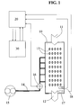
- the diagram in Figure 1 shows a tank 10 including at least one inlet 11 for inflowing waste water and one or more outlets 12 for outflowing waste water. Pressurized air is blown into the tank 10, and consequently into the waste water travelling therethrough, by a network of nozzles 13 fed by a main duct 14. Air is blown into the duct 14 by at least one compressor or fan 15 and the flow rate of the air to the network of nozzles 13 is regulated by at least one regulation device 16.
- Detectors are provided for the process parameters, in particular at least one sensor 17 to measure the concentration of ammonia nitrogen in the waste water and at least one sensor 18 to measure the concentration of dissolved oxygen in the waste water.
- the signals representing the values acquired on-line by the detectors 17 and 18 are sent to a unit 20 for the management of input and output signals to and from the control unit 30.
- the control unit 30 is, for example, composed of a computer programmed to perform all the instructions required to implement the fuzzy logic rules used in the process control, including transformation (defuzzification) of the results obtained by applying the fuzzy logic rules to control values and/or signals destined to be sent to the regulation device 16.
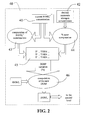
- a first control level or module 40 which receives an input value 41 corresponding to the concentration of ammonia nitrogen detected by the sensor 17 and a pre-established value 42 corresponding to the concentration of ammonia nitrogen desired.
- the first value 41 is used to calculate the variation rate of the concentration of ammonia nitrogen along a pre-established time interval (block 43), and both values 41 and 42 are used to calculate the percentage error between the desired value and the value effectively detected (block 44).
- the results of the calculations performed in the blocks 43 and 44 are presented as input parameters to a program 45 which uses the fuzzy logic rules to calculate any variation in the percentage of the DOSP (Dissolved Oxygen Set Point), compared to the previously calculated value.
- DOSP Dissolved Oxygen Set Point
- MacVicar-Whelan rule bases are, for example, used.
- An example of a rule of this type applied in this context could be:
- the membership functions can, for example, be defined on the basis of Gaussian, trapezoidal or similar functions.
- the fuzzy logic rules implemented in the program 45 can, for example, express membership functions for the difference between the detected and desired value of the concentration of ammonia nitrogen, membership functions for the variation speed of the concentration of ammonia nitrogen, and membership functions for the percentage variation of the set point of the concentration of dissolved oxygen.
- the percentage value output from the program 45, together with the previous DOSP f value, is used to calculate the new set point value DOSP n for the concentration of dissolved oxygen (block 46) which will be used as the basis for varying the supply of air in the waste water flowing inside the tank 10.
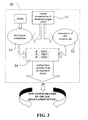
- DOSP n value output from the first level 40 is input into a second level or module 50 represented in Figure 3.
- the module 50 also receives an input value 51 corresponding to the current concentration of dissolved oxygen detected by the sensor 18.
- the value 51 is used to calculate the variation rate of the concentration of dissolved oxygen along a pre-established time interval (block 52).
- the DOSP n value is used together with the value 51 to calculate the percentage error between the DOSP n value and the value effectively detected (block 53).
- the signal corresponding to this value is then transmitted to the regulation device 16 through the unit 20 dedicated to management of the input and output signals of the unit 30 ( Figure 1).
- MacVicar-Whelan type fuzzy logic base rules are, for example, used.
- An example of a rule of this type applied in this context could be:
- membership functions can, for example, be defined on the basis of Gaussian, trapezoidal or similar functions.
- the fuzzy logic rules implemented in the program 54 can, for example, express membership functions for the difference between the detected value and the calculated set point of the concentration of dissolved oxygen, membership functions for the variation speed of the concentration of dissolved oxygen, and membership functions for the variation of the air flow.
- a control system according to the present invention was experimented in a plant which on average treats 85,000 m 3 /day of waste waters prevalently of domestic origin.
- the compartment in which the aerobic purifying process takes place is composed of four tanks in parallel.
- One of the tanks was subjected to control by a device according to the present invention, while in the other three tanks the existing system was left, i.e. a system with a PID controller with a fixed set point with regard to the concentration of dissolved oxygen.
- the air feed system is composed of three centrifugal compressors, each having a maximum flow rate of 12,100 Nm 3 /hour, with a controlled valve for each tank, for separate regulation of the air flow.
- Management is, in this case, performed by a PID controller provided to maintain the pressure in the air circuit at a pre-established constant value (generally of 4.8 m H 2 O).
- Two oxygen sensors were installed in proximity to the outlet of each tank and the current value of the concentration of dissolved oxygen is calculated as an average of the measurements detected by each of the two sensors.
- the value detected for the concentration of dissolved oxygen is input into the PID controller.
- This controller has the task of maintaining this value as close as possible to the set point pre-established for the concentration of dissolved oxygen in a specific tank, in particular acting on a controlled valve associated with the corresponding tank.
- the control according to the present invention was instead applied calculating the set point for the concentration of dissolved oxygen every 15 minutes.
- the rate of variation of the concentration of ammonia nitrogen is calculated on the values relative to the last 30 minutes, while the rate of variation of the concentration of dissolved oxygen is calculated on the basis of the values relative to the last 12 minutes.
- the variation of the position of the controlled valve is calculated every minute.
- the sensors for detecting the concentration of ammonia nitrogen and the concentration of dissolved oxygen are products identified by the trade names FILTRAX, AMTAX and ANALON DO-1 produced by the company DR LANGE s.r.l. of Rozzano (MI).
- Interface between the sensors and the control logic is obtained using STAR-OHF (32 bit CPU), ADA and DOB boards produced by the company SDI AUTOMAZIONE INDUSTRIALE of Trezzano sul Naviglio (MI).
- the concentration of ammonia was found to vary by approximately 0 to approximately 10 mg N/litre over the course of one day, while with the controller of the present invention concentrations varying from 4.3 to 8.9 mg N/litre were detected.
- the value of difference between the maximum and minimum concentration of ammonia nitrogen with the controller according to the present invention is approximately 6.5 mg N/litre, while with convention controllers the mean value calculated is approximately 9.9 mg N/litre.
- a reduction of the amplitude of fluctuation of approximately 34% is obtained, which is a considerable improvement both as regards process efficiency, as extreme situations of poor or complete nitrification must be avoided, and as regards stability on a daily scale.
- the mean values were of approximately 1.3 mg N/litre with conventional controllers and of approximately 5.2 mg N/litre with a controller according to the present invention.
- the control produced according to the present invention with variable set point for the concentration of dissolved oxygen, maintains the value of concentration of ammonia nitrogen stable close to the desired level, therefore without requesting a pointless supply of air with consequent waste of energy.
- the controller according to the present invention ensures that the concentration of dissolved oxygen present in the waste waters regularly follows the variation of the set point, with limited fluctuations, while with conventional controllers fluctuations much higher than the fixed set point occur.
- the maximum difference between the effective value measured for the concentration of dissolved oxygen and the set point was 0.5 mg N/litre, while for conventional controllers it was 0.86 mgN/litre.
Landscapes
- Engineering & Computer Science (AREA)
- Artificial Intelligence (AREA)
- Software Systems (AREA)
- Physics & Mathematics (AREA)
- Health & Medical Sciences (AREA)
- Mathematical Physics (AREA)
- Fuzzy Systems (AREA)
- Computer Vision & Pattern Recognition (AREA)
- Evolutionary Computation (AREA)
- Medical Informatics (AREA)
- General Physics & Mathematics (AREA)
- Automation & Control Theory (AREA)
- Feedback Control In General (AREA)
- Activated Sludge Processes (AREA)
Abstract
Description
- The present invention relates in general to management of the biological process in waste water purifying plants and, in particular, a method and a device for continuous controlling the supply of oxygen in waste waters flowing in an oxidation tank.
- In waste water purifying plants the main phase of treatment is represented by the biological process. In this phase the waste waters are made to flow in a large tank (several hundreds or thousands of cubic meters) containing a specific quantity of micro-organisms (bacteria, protozoa, etc.) which perform degradation of pollutants.
- The principal phase of the biological treatment is aerobic, and it is consequently necessary to maintain a correct concentration of oxygen in the waste water in order to guarantee optimal operating conditions for the micro-organisms. This is obtained by supplying oxygen continuously (oxygen can be supplied by blowing air, blowing pure oxygen, remixing the sewage, etc.) to the waste water present inside the tank. This supply must be delivered in a particularly homogeneous way and in sufficient quantity to allow correct implementation of the purifying process.
- In fact, the supply of oxygen has a considerable influence on various aspects of the treatment, such as the removal of nitrogen, the sedimentation of sludge, and the formation and/or growth of filamentous micro-organisms.
- At the same time, the cost of energy for supplying oxygen through blown air is one of the major cost items in the management of a waste water purifying plant.
- In prior art, regulation of the air fed to the biological treatment tank is generally based on detection of the concentration of dissolved oxygen (DO) in the waste water present in the treatment tank. The control system used consequently acts directly on the compressors (or machinery used to blow air) or on appropriate devices (such as valves) in order to vary or interrupt the air flow.
- In general, in the more sophisticated known solutions, advanced systems are used for the supply of air, associated with industrial controllers of the PID type, for which a set point is set for a variable parameter, typically the concentration of dissolved oxygen. Nonetheless, it has been found that the dynamics of the treatment process are nonlinear and therefore difficult to control using a typically linear control device such as a PID.
- In particular, one of the limits of PID controllers in this type of application depends on the process conditions, in which there are considerable variations in both the short and the long term and which have particular influence on the concentration of dissolved oxygen. Moreover, in particular conditions, there can be very wide fluctuations with respect to the set point.
- Consequently, the efficiency of the biological process is compromised under various aspects. Firstly, the differences between the effective amount of oxygen required and the amount provided instantly are in any case counter-productive. In fact, if too little oxygen is supplied, the aerobic process is slowed down, while an excessive concentration of dissolved oxygen can, for example, have a negative influence on the efficiency of the denitrification process. Secondly, high fluctuations with respect to the pre-established set point make the purifying process instable due to the continuous and rapid variations in the concentration of dissolved oxygen to which the biomass is subjected.
- More recently, some researchers have shown the efficacy of controllers produced according to the rules of fuzzy logic to manage plants of this type. Nonetheless, this approach has until now been limited to an experimental level on reduced scale, where fluctuations of certain parameters involved in control are in any case limited, and without taking into account aspects undoubtedly more practical from the viewpoint of the actual management of real plants.
- The Unites States patent no. US-6093322 (Bongards) describes an example of application of fuzzy logic to control this type of process. It is based on the measurement of the redox potential to define the times in which to switch on/switch off the aeration systems to perform an alternate nitrification and denitrification process.
- A particularly important aspect is represented by the waste of energy which occurs when the quantity of blown air is greater than the effective requirement. This aspect becomes more important if we consider the usual practice of maintaining high set points with regard to the concentration of dissolved oxygen, i.e., values suitable only when operating in the worst operating conditions, as it is in any case deemed that an excess supply of air is safer than a shortage in supply.
- It should be taken into account that the cost of supplying air is, however, a substantial item (approximately 20-30%) of the overall management costs of a purifying plant.
- This being stated, the general object of the present invention is to propose a method and a device which allow optimization of the supply of air to the aerobic treatment process for waste waters in a purifying plant.
- A specific object of the present invention is to reduce treatment costs correlated principally to the supply of oxygen through blowing air, preventing, above all, an excess supply.
- Another specific object of the present invention is to guarantee process stability, notwithstanding the variability of the characteristics and of the parameters which influence the treatment.
- A further specific object of the present invention is to maintain adequate treatment efficiency at all times.
- These objects are attained by the present invention, which relates to a method for continuously controlling the aerobic biological treatment of waste waters in a purifying plant, wherein the waste waters flowing continuously in an oxidation tank are subjected to aeration through the blowing of pressurized air. The method is characterized in that the flow rate of air blown into the waste water is substantially continuously regulated by at least a first control level, which substantially continuously modifies the set point of the concentration of dissolved oxygen in the waste waters.
- Preferably, the first control level modifies the set point of the concentration of dissolved oxygen in the waste waters as a function of at least the value of concentration of ammonia nitrogen detected in the waste waters and of at least a desired value for the concentration of ammonia nitrogen.
- By varying the set point of the concentration of dissolved oxygen as a function of the variations in the process parameters effectively detected, preferably measured "on-line", it is possible to obtain noteworthy process stability, both in the short and in the long term.
- Calculation of a new set point for the concentration of dissolved oxygen is implemented very frequently with respect to the dynamics of the processes in play, for example, at least every 10-20 minutes, so as to guarantee substantially continuous control of the process also for variations in the parameters that can occur in the short term.
- According to an advantageous aspect of the present invention, the first level of control uses fuzzy logic rules, through which membership functions are expressed at least for the difference between detected and desired value of the concentration of ammonia nitrogen, membership functions are expressed at least for the variation speed of the concentration of ammonia nitrogen and membership functions are expressed at least for the percentage variation of the set point for the concentration of dissolved oxygen.
- According to another advantageous aspect of the present invention, at least a second control level is provided to modify in a substantially continuous way the flow rate of air blown into the oxidation tank as a function of the set point of the concentration of dissolved oxygen calculated in a substantially continuous way by the first control level and of the value effectively detected for the concentration of dissolved oxygen in the waste waters.
- Also in this second control level fuzzy logic rules are preferably used. In this case, the fuzzy logic rules express membership functions at least for the difference between detected value and set point of the concentration of dissolved oxygen, membership functions at least for the variation speed of the concentration of dissolved oxygen and membership functions at least for the variation of the flow rate of air blown into the tank.
- The invention also relates to a device for continuously controlling the aerobic biological treatment in a waste water purifying plant, including at least one plant for blowing pressurized air into the waste waters flowing continuously in an oxidation tank and control means to vary, in a substantially continuous way, the flow rate of air blown into the waste waters, characterized in that the control means include at least a first control module which substantially continuously modifies the set point of the concentration of dissolved oxygen in the waste waters.
- In general, it has been found in a practical way that the principles of the present invention, especially those relating to the substantially continuous variation of the set point for the concentration of dissolved oxygen, allow considerably savings to be obtained in the management of purifying plants, by appropriately optimizing the consumption of electrical energy used to supply air to the oxidation tanks.
- The adoption of fuzzy logic rules also facilitates control for experts in the environmental field without requiring particular know-how in the field of control systems.
- Further characteristics and advantages of the present invention shall be more apparent from the description hereunder with reference to the accompanying drawings wherein:
- Figure 1 is a general diagram of a control device according to the present invention applied to a waste water purifying plant;
- Figure 2 is a diagram illustrating operation of the first control module of a device according to the present invention; and
- Figure 3 is a diagram illustrating operation of the second control module of a device according to the present invention.
- The diagram in Figure 1 shows a
tank 10 including at least one inlet 11 for inflowing waste water and one ormore outlets 12 for outflowing waste water. Pressurized air is blown into thetank 10, and consequently into the waste water travelling therethrough, by a network ofnozzles 13 fed by amain duct 14. Air is blown into theduct 14 by at least one compressor orfan 15 and the flow rate of the air to the network ofnozzles 13 is regulated by at least one regulation device 16. - Detectors are provided for the process parameters, in particular at least one
sensor 17 to measure the concentration of ammonia nitrogen in the waste water and at least onesensor 18 to measure the concentration of dissolved oxygen in the waste water. - The signals representing the values acquired on-line by the
detectors unit 20 for the management of input and output signals to and from thecontrol unit 30. - The
control unit 30 is, for example, composed of a computer programmed to perform all the instructions required to implement the fuzzy logic rules used in the process control, including transformation (defuzzification) of the results obtained by applying the fuzzy logic rules to control values and/or signals destined to be sent to the regulation device 16. - Referring now also to Figure 2, a first control level or
module 40 is provided, which receives aninput value 41 corresponding to the concentration of ammonia nitrogen detected by thesensor 17 and apre-established value 42 corresponding to the concentration of ammonia nitrogen desired. - The
first value 41 is used to calculate the variation rate of the concentration of ammonia nitrogen along a pre-established time interval (block 43), and bothvalues - The results of the calculations performed in the
blocks program 45 which uses the fuzzy logic rules to calculate any variation in the percentage of the DOSP (Dissolved Oxygen Set Point), compared to the previously calculated value. - The MacVicar-Whelan rule bases are, for example, used. An example of a rule of this type applied in this context could be:
- IF nitrification is "low"
- AND the variation rate is "small positive"
- THEN the variation in DOSP is "high positive"
-
- The membership functions can, for example, be defined on the basis of Gaussian, trapezoidal or similar functions.
- In general, the fuzzy logic rules implemented in the
program 45 can, for example, express membership functions for the difference between the detected and desired value of the concentration of ammonia nitrogen, membership functions for the variation speed of the concentration of ammonia nitrogen, and membership functions for the percentage variation of the set point of the concentration of dissolved oxygen. - The percentage value output from the
program 45, together with the previous DOSPf value, is used to calculate the new set point value DOSPn for the concentration of dissolved oxygen (block 46) which will be used as the basis for varying the supply of air in the waste water flowing inside thetank 10. - In fact, the DOSPn value output from the
first level 40 is input into a second level ormodule 50 represented in Figure 3. - Besides the DOSPn value, the
module 50 also receives aninput value 51 corresponding to the current concentration of dissolved oxygen detected by thesensor 18. - The
value 51 is used to calculate the variation rate of the concentration of dissolved oxygen along a pre-established time interval (block 52). At the same time, the DOSPn value is used together with thevalue 51 to calculate the percentage error between the DOSPn value and the value effectively detected (block 53). - The results of the calculations implemented in the
blocks program 54 which also uses fuzzy logic rules to determine any operation of the regulation device 16 in order to vary the supply of air according to the parameters established by the control device. - The signal corresponding to this value is then transmitted to the regulation device 16 through the
unit 20 dedicated to management of the input and output signals of the unit 30 (Figure 1). - Also in the case of the
program 54 MacVicar-Whelan type fuzzy logic base rules are, for example, used. An example of a rule of this type applied in this context could be: - IF the difference between current DO and DOSP is "small negative"
- AND the variation rate is "high positive"
- THEN the variation of the flow rate is "small negative"
-
- Also in this case the membership functions can, for example, be defined on the basis of Gaussian, trapezoidal or similar functions.
- In general, the fuzzy logic rules implemented in the
program 54 can, for example, express membership functions for the difference between the detected value and the calculated set point of the concentration of dissolved oxygen, membership functions for the variation speed of the concentration of dissolved oxygen, and membership functions for the variation of the air flow. - A control system according to the present invention was experimented in a plant which on average treats 85,000 m3/day of waste waters prevalently of domestic origin.
- The compartment in which the aerobic purifying process takes place is composed of four tanks in parallel. One of the tanks was subjected to control by a device according to the present invention, while in the other three tanks the existing system was left, i.e. a system with a PID controller with a fixed set point with regard to the concentration of dissolved oxygen.
- As a whole, the air feed system is composed of three centrifugal compressors, each having a maximum flow rate of 12,100 Nm3/hour, with a controlled valve for each tank, for separate regulation of the air flow.
- Large variations in the air requirements are managed by switching on and off one or more compressors, while smaller variations are obtained by regulating internal devices present in each compressor. Management is, in this case, performed by a PID controller provided to maintain the pressure in the air circuit at a pre-established constant value (generally of 4.8 m H2O).
- Two oxygen sensors were installed in proximity to the outlet of each tank and the current value of the concentration of dissolved oxygen is calculated as an average of the measurements detected by each of the two sensors.
- In the conventional control system, the value detected for the concentration of dissolved oxygen is input into the PID controller. This controller has the task of maintaining this value as close as possible to the set point pre-established for the concentration of dissolved oxygen in a specific tank, in particular acting on a controlled valve associated with the corresponding tank.
- The control according to the present invention was instead applied calculating the set point for the concentration of dissolved oxygen every 15 minutes. The rate of variation of the concentration of ammonia nitrogen is calculated on the values relative to the last 30 minutes, while the rate of variation of the concentration of dissolved oxygen is calculated on the basis of the values relative to the last 12 minutes.
- The variation of the position of the controlled valve is calculated every minute. A butterfly valve with a diameter of 250 mm coupled to an electric servomotor for regulation, with gear reducer complete with local position indicator, is used.
- The sensors for detecting the concentration of ammonia nitrogen and the concentration of dissolved oxygen are products identified by the trade names FILTRAX, AMTAX and ANALON DO-1 produced by the company DR LANGE s.r.l. of Rozzano (MI).
- Interface between the sensors and the control logic is obtained using STAR-OHF (32 bit CPU), ADA and DOB boards produced by the company SDI AUTOMAZIONE INDUSTRIALE of Trezzano sul Naviglio (MI).
- Experimentation was carried out for a period of approximately one year on the "Città di Verona" purifying plant located in Verona and managed by the company AGSM Verona S.p.A., with continuous comparison with the results determined by conventional controllers.
- The value of 7.0 mg of NH4 +/litre was established as desired value for the concentration of ammonia nitrogen, in particular taking account of the expected variations around this value of reference, but nonetheless considerably lower than the limit established by law for this purifying plant of 15 mg of NH4 +/litre.
- In particularly critical conditions, i.e. in days with a particularly high load, with conventional (PID) controllers, the concentration of ammonia was found to vary by approximately 0 to approximately 10 mg N/litre over the course of one day, while with the controller of the present invention concentrations varying from 4.3 to 8.9 mg N/litre were detected.
- On average, in the course of one day, the value of difference between the maximum and minimum concentration of ammonia nitrogen with the controller according to the present invention is approximately 6.5 mg N/litre, while with convention controllers the mean value calculated is approximately 9.9 mg N/litre. A reduction of the amplitude of fluctuation of approximately 34% is obtained, which is a considerable improvement both as regards process efficiency, as extreme situations of poor or complete nitrification must be avoided, and as regards stability on a daily scale.
- Even in less critical conditions, i.e. with a normal or slightly increased load with respect to the maximum load of the plant, conventional controllers maintained the concentration of ammonia at very low values, i.e. approximately 0.5 mg N/litre, while with the controller of the present invention the values varied from 1.7 to 7.3 mg N/litre.
- The mean values were of approximately 1.3 mg N/litre with conventional controllers and of approximately 5.2 mg N/litre with a controller according to the present invention. This means that in limited load conditions, a fixed set point for the concentration of dissolved oxygen gives rise to an excess supply of air which practically cancels the concentration of ammonia nitrogen, resulting in a considerable waste of energy. On the contrary, the control produced according to the present invention, with variable set point for the concentration of dissolved oxygen, maintains the value of concentration of ammonia nitrogen stable close to the desired level, therefore without requesting a pointless supply of air with consequent waste of energy.
- The controller according to the present invention ensures that the concentration of dissolved oxygen present in the waste waters regularly follows the variation of the set point, with limited fluctuations, while with conventional controllers fluctuations much higher than the fixed set point occur. In particular, the maximum difference between the effective value measured for the concentration of dissolved oxygen and the set point was 0.5 mg N/litre, while for conventional controllers it was 0.86 mgN/litre.
- Another considerable advantage was found in terms of energy consumption. Comparison was made by applying alternatively in time a completely conventional control method (first method) and a mixed control method, with only one of the four tanks controlled according to the present invention (second method).
- With the first operating method, a consumption of 16,491 kWh/day was obtained, while with the second operating method consumption was of 15,738 kWh/day, thereby obtaining a saving of approximately 4.5% with only one of the tanks controlled according to the present invention. It is therefore right to expect further savings by applying the control according to the present invention to all the tanks in the biological compartment of the plant.
Claims (16)
- A method for continuously controlling the aerobic biological treatment of waste waters in a purifying plant, wherein said waste waters flowing continuously in an oxidation tank are subjected to aeration through the blowing of pressurized air, characterized in that the flow rate of air blown into the waste water is substantially continuously regulated by at least a first control level which substantially continuously modifies the set point of the concentration of dissolved oxygen in the waste waters.
- The method according to claim 1, wherein at least the values of the concentration of ammonia nitrogen and of the concentration of dissolved oxygen in said waste waters are detected.
- The method according to claim 1, wherein said first control level modifies the set point of the concentration of dissolved oxygen in said waste waters as a function at least of the value of the concentration of ammonia nitrogen detected in said waste waters and at least of a pre-established value for said concentration of ammonia nitrogen.
- The method according to claim 1, wherein said first control level uses fuzzy logic rules.
- The method according to claim 4, wherein said fuzzy logic rules express membership functions at least for the difference between detected and desired value of the concentration of ammonia nitrogen, membership functions at least for the variation speed of the concentration of ammonia nitrogen and membership functions at least for the percentage variation of the set point for the concentration of dissolved oxygen.
- The method according to claim 1, wherein at least a second control level is provided to modify in a substantially continuous way the flow rate of air blown into said waste waters as a function of the set point of the concentration of dissolved oxygen calculated in a substantially continuous way by said first control level and of the value detected for the concentration of dissolved oxygen in said waste waters.
- The method according to claim 6, wherein said second control level uses fuzzy logic rules.
- The method according to claim 7, wherein said fuzzy logic rules express membership functions at least for the difference between detected value and set point of the concentration of dissolved oxygen, membership functions at least for the variation speed of the concentration of dissolved oxygen and membership functions at least for the variation of the flow rate of air blown into said waster waters.
- A device for continuously controlling the aerobic biological treatment of waste waters in a purifying plant, including at least one system for blowing pressurized air into the waste waters flowing continuously in an oxidation tank and control means to vary, in a substantially continuous way, the flow rate of air blown into said waste waters, characterized in that said control means include at least a first control module which substantially continuously modifies the set point of the concentration of dissolved oxygen in said waste waters.
- The device according to claim 9, wherein means are provided to detect at least the values relative to the concentration of ammonia nitrogen and to the concentration of dissolved oxygen in said waste waters.
- The device according to claim 9, wherein said first control module is programmed to modify the set point of the concentration of dissolved oxygen in said waste waters as a function of at least the value detected for the concentration of ammonia nitrogen and of at least a pre-established value for said concentration of ammonia nitrogen in said waste waters.
- The device according to claim 9, wherein said first control module includes at least one processing unit programmed with fuzzy logic rules.
- The device according to claim 12, wherein said fuzzy logic rules express membership functions at least for the difference between the detected and desired value of the concentration of ammonia nitrogen, membership functions at least for the variation speed of the concentration of ammonia nitrogen, and membership functions at least for the percentage variation of the set point of the concentration of dissolved oxygen.
- The device according to claim 9, wherein said control means include at least a second control module to modify in a substantially continuous way the flow rate of air blown into said waste waters as a function of the set point of the concentration of dissolved oxygen calculated in a substantially continuous way by said first control module and of the value effectively detected of the concentration of dissolved oxygen in said waste waters.
- The device according to claim 14, wherein said second control module includes at least one processing unit programmed with fuzzy logic rules.
- The device according to claim 15, wherein said fuzzy logic rules express membership functions at least for the difference between detected value and set point of the concentration of dissolved oxygen, membership functions at least for the variation speed of the concentration of dissolved oxygen and membership functions at least for the variation of the flow rate of air blown into said waster waters.
Applications Claiming Priority (2)
| Application Number | Priority Date | Filing Date | Title |
|---|---|---|---|
| ITMI20040977 | 2004-05-17 | ||
| ITMI20040977 ITMI20040977A1 (en) | 2004-05-17 | 2004-05-17 | MERTODE AND DEVICE FOR THE CONTROL OF THE BIOLOGICAL PROCESS IN PURIFICATION PLANTS |
Publications (2)
| Publication Number | Publication Date |
|---|---|
| EP1598712A1 true EP1598712A1 (en) | 2005-11-23 |
| EP1598712B1 EP1598712B1 (en) | 2016-08-31 |
Family
ID=34979668
Family Applications (1)
| Application Number | Title | Priority Date | Filing Date |
|---|---|---|---|
| EP05010111.2A Not-in-force EP1598712B1 (en) | 2004-05-17 | 2005-05-10 | Method and device for controlling the biological process in waste-water treatment plants |
Country Status (2)
| Country | Link |
|---|---|
| EP (1) | EP1598712B1 (en) |
| IT (1) | ITMI20040977A1 (en) |
Cited By (2)
| Publication number | Priority date | Publication date | Assignee | Title |
|---|---|---|---|---|
| ES2323257A1 (en) * | 2007-11-30 | 2009-07-09 | Mondragon Sistemas E Informacion, S.Coop | Advanced automatic control system of a wastewater treatment plant (Machine-translation by Google Translate, not legally binding) |
| ITRM20130346A1 (en) * | 2013-06-17 | 2014-12-18 | Chemitec S R L | METHOD AND CONTROL SYSTEM OF A PROCESS OF BIOLOGICAL TREATMENT OF WASTE WATERS OF CIVIL ORIGIN |
Citations (1)
| Publication number | Priority date | Publication date | Assignee | Title |
|---|---|---|---|---|
| EP1376276A1 (en) * | 2002-06-21 | 2004-01-02 | H2L Co., Ltd | An AI based control system and method for treating sewage/waste water by means of a neural network and a back-propagation algorithm |
-
2004
- 2004-05-17 IT ITMI20040977 patent/ITMI20040977A1/en unknown
-
2005
- 2005-05-10 EP EP05010111.2A patent/EP1598712B1/en not_active Not-in-force
Patent Citations (1)
| Publication number | Priority date | Publication date | Assignee | Title |
|---|---|---|---|---|
| EP1376276A1 (en) * | 2002-06-21 | 2004-01-02 | H2L Co., Ltd | An AI based control system and method for treating sewage/waste water by means of a neural network and a back-propagation algorithm |
Cited By (5)
| Publication number | Priority date | Publication date | Assignee | Title |
|---|---|---|---|---|
| ES2323257A1 (en) * | 2007-11-30 | 2009-07-09 | Mondragon Sistemas E Informacion, S.Coop | Advanced automatic control system of a wastewater treatment plant (Machine-translation by Google Translate, not legally binding) |
| ITRM20130346A1 (en) * | 2013-06-17 | 2014-12-18 | Chemitec S R L | METHOD AND CONTROL SYSTEM OF A PROCESS OF BIOLOGICAL TREATMENT OF WASTE WATERS OF CIVIL ORIGIN |
| WO2014203127A1 (en) | 2013-06-17 | 2014-12-24 | Chemitec S.R.L. | Method and apparatus for controlling a process of biological treatment of wastewater of civil origin |
| CN105531235A (en) * | 2013-06-17 | 2016-04-27 | 凯米泰克有限公司 | Method and apparatus for controlling a process of biological treatment of wastewater of civil origin |
| CN105531235B (en) * | 2013-06-17 | 2019-04-16 | 凯米泰克有限公司 | For controlling the method and device of the biological treatment process of civilian source waste water |
Also Published As
| Publication number | Publication date |
|---|---|
| ITMI20040977A1 (en) | 2004-08-17 |
| EP1598712B1 (en) | 2016-08-31 |
Similar Documents
| Publication | Publication Date | Title |
|---|---|---|
| Baeza et al. | Improving the nitrogen removal efficiency of an A2/O based WWTP by using an on-line knowledge based expert system | |
| CN107986428B (en) | Sewage treatment accurate aeration method | |
| CN202758178U (en) | Intelligent dynamic aeration control system | |
| Zhao et al. | A novel control strategy for improved nitrogen removal in an alternating activated sludge process—Part I. Process analysis | |
| CN101913699A (en) | Methods of providing an aerobic medium in a wastewater treatment bioreactor compartment and related systems | |
| CN109592804B (en) | Sewage treatment near-optimal precise aeration method | |
| Chen et al. | Smart energy savings for aeration control in wastewater treatment | |
| Piotrowski et al. | Mixed integer nonlinear optimization of biological processes in wastewater sequencing batch reactor | |
| CN107555590A (en) | A kind of multi-point combination formula accurate aeration control method | |
| Sorensen et al. | Optimization of a nitrogen‐removing biological wastewater treatment plant using on‐line measurements | |
| JP4188200B2 (en) | Plant-wide optimum process controller | |
| CN108678986A (en) | The control method and device of sewage treatment plant's air blower automatic adjustment and marshalling operation | |
| EP1598712B1 (en) | Method and device for controlling the biological process in waste-water treatment plants | |
| Hirsch et al. | Supervisory control system for adaptive phase and work cycle management of sequencing wastewater treatment plant | |
| Nam et al. | On‐line integrated control system for an industrial activated sludge process | |
| Devisscher et al. | Feasibility of automatic chemicals dosage control–a full-scale evaluation | |
| CN201071325Y (en) | Oxygen supply system for aeration tank | |
| Thunberg et al. | Energy optimization of the aeration process at Käppala wastewater treatment plant | |
| WO1998003434A1 (en) | Device for controlling dissolved oxygen concentration of aeration tank, device for controlling temperature of aeration tank, device for controlling flow rate of raw water for homogeneous-flow liquid surface, and wastewater treatment equipment used in activated sludge process | |
| Van Nguyen et al. | Combined ILC and PI regulator for wastewater treatment plants | |
| JP2002219481A (en) | Equipment for controlling concentration of dissolved oxygen in aerating tank | |
| CN115246680A (en) | Accurate intermittent aeration control system and method | |
| Mallu et al. | Optimization of air flowrate under different control strategies focus on biological process in wastewater treatment plant | |
| JP2000325980A (en) | Sewage treatment method and apparatus | |
| Piotrowski | Comparison of two nonlinear predictive control algorithms for dissolved oxygen tracking problem at wwtp |
Legal Events
| Date | Code | Title | Description |
|---|---|---|---|
| PUAI | Public reference made under article 153(3) epc to a published international application that has entered the european phase |
Free format text: ORIGINAL CODE: 0009012 |
|
| AK | Designated contracting states |
Kind code of ref document: A1 Designated state(s): AT BE BG CH CY CZ DE DK EE ES FI FR GB GR HU IE IS IT LI LT LU MC NL PL PT RO SE SI SK TR |
|
| AX | Request for extension of the european patent |
Extension state: AL BA HR LV MK YU |
|
| 17P | Request for examination filed |
Effective date: 20060515 |
|
| AKX | Designation fees paid |
Designated state(s): AT BE BG CH CY CZ DE DK EE ES FI FR GB GR HU IE IS IT LI LT LU MC NL PL PT RO SE SI SK TR |
|
| 17Q | First examination report despatched |
Effective date: 20080225 |
|
| GRAP | Despatch of communication of intention to grant a patent |
Free format text: ORIGINAL CODE: EPIDOSNIGR1 |
|
| RIC1 | Information provided on ipc code assigned before grant |
Ipc: C02F 3/00 20060101ALN20160119BHEP Ipc: G05B 13/02 20060101AFI20160119BHEP |
|
| INTG | Intention to grant announced |
Effective date: 20160222 |
|
| GRAR | Information related to intention to grant a patent recorded |
Free format text: ORIGINAL CODE: EPIDOSNIGR71 |
|
| GRAS | Grant fee paid |
Free format text: ORIGINAL CODE: EPIDOSNIGR3 |
|
| GRAA | (expected) grant |
Free format text: ORIGINAL CODE: 0009210 |
|
| RIC1 | Information provided on ipc code assigned before grant |
Ipc: C02F 3/00 20060101ALN20160711BHEP Ipc: G05B 13/02 20060101AFI20160711BHEP |
|
| INTG | Intention to grant announced |
Effective date: 20160721 |
|
| AK | Designated contracting states |
Kind code of ref document: B1 Designated state(s): AT BE BG CH CY CZ DE DK EE ES FI FR GB GR HU IE IS IT LI LT LU MC NL PL PT RO SE SI SK TR |
|
| REG | Reference to a national code |
Ref country code: CH Ref legal event code: EP Ref country code: GB Ref legal event code: FG4D |
|
| REG | Reference to a national code |
Ref country code: IE Ref legal event code: FG4D |
|
| REG | Reference to a national code |
Ref country code: DE Ref legal event code: R096 Ref document number: 602005050098 Country of ref document: DE |
|
| REG | Reference to a national code |
Ref country code: AT Ref legal event code: REF Ref document number: 825498 Country of ref document: AT Kind code of ref document: T Effective date: 20161015 |
|
| REG | Reference to a national code |
Ref country code: LT Ref legal event code: MG4D |
|
| REG | Reference to a national code |
Ref country code: NL Ref legal event code: MP Effective date: 20160831 |
|
| REG | Reference to a national code |
Ref country code: AT Ref legal event code: MK05 Ref document number: 825498 Country of ref document: AT Kind code of ref document: T Effective date: 20160831 |
|
| PG25 | Lapsed in a contracting state [announced via postgrant information from national office to epo] |
Ref country code: LT Free format text: LAPSE BECAUSE OF FAILURE TO SUBMIT A TRANSLATION OF THE DESCRIPTION OR TO PAY THE FEE WITHIN THE PRESCRIBED TIME-LIMIT Effective date: 20160831 Ref country code: FI Free format text: LAPSE BECAUSE OF FAILURE TO SUBMIT A TRANSLATION OF THE DESCRIPTION OR TO PAY THE FEE WITHIN THE PRESCRIBED TIME-LIMIT Effective date: 20160831 |
|
| PG25 | Lapsed in a contracting state [announced via postgrant information from national office to epo] |
Ref country code: SE Free format text: LAPSE BECAUSE OF FAILURE TO SUBMIT A TRANSLATION OF THE DESCRIPTION OR TO PAY THE FEE WITHIN THE PRESCRIBED TIME-LIMIT Effective date: 20160831 Ref country code: NL Free format text: LAPSE BECAUSE OF FAILURE TO SUBMIT A TRANSLATION OF THE DESCRIPTION OR TO PAY THE FEE WITHIN THE PRESCRIBED TIME-LIMIT Effective date: 20160831 Ref country code: AT Free format text: LAPSE BECAUSE OF FAILURE TO SUBMIT A TRANSLATION OF THE DESCRIPTION OR TO PAY THE FEE WITHIN THE PRESCRIBED TIME-LIMIT Effective date: 20160831 Ref country code: ES Free format text: LAPSE BECAUSE OF FAILURE TO SUBMIT A TRANSLATION OF THE DESCRIPTION OR TO PAY THE FEE WITHIN THE PRESCRIBED TIME-LIMIT Effective date: 20160831 Ref country code: GR Free format text: LAPSE BECAUSE OF FAILURE TO SUBMIT A TRANSLATION OF THE DESCRIPTION OR TO PAY THE FEE WITHIN THE PRESCRIBED TIME-LIMIT Effective date: 20161201 |
|
| PG25 | Lapsed in a contracting state [announced via postgrant information from national office to epo] |
Ref country code: RO Free format text: LAPSE BECAUSE OF FAILURE TO SUBMIT A TRANSLATION OF THE DESCRIPTION OR TO PAY THE FEE WITHIN THE PRESCRIBED TIME-LIMIT Effective date: 20160831 Ref country code: EE Free format text: LAPSE BECAUSE OF FAILURE TO SUBMIT A TRANSLATION OF THE DESCRIPTION OR TO PAY THE FEE WITHIN THE PRESCRIBED TIME-LIMIT Effective date: 20160831 |
|
| REG | Reference to a national code |
Ref country code: FR Ref legal event code: PLFP Year of fee payment: 13 |
|
| PG25 | Lapsed in a contracting state [announced via postgrant information from national office to epo] |
Ref country code: PT Free format text: LAPSE BECAUSE OF FAILURE TO SUBMIT A TRANSLATION OF THE DESCRIPTION OR TO PAY THE FEE WITHIN THE PRESCRIBED TIME-LIMIT Effective date: 20170102 Ref country code: DK Free format text: LAPSE BECAUSE OF FAILURE TO SUBMIT A TRANSLATION OF THE DESCRIPTION OR TO PAY THE FEE WITHIN THE PRESCRIBED TIME-LIMIT Effective date: 20160831 Ref country code: PL Free format text: LAPSE BECAUSE OF FAILURE TO SUBMIT A TRANSLATION OF THE DESCRIPTION OR TO PAY THE FEE WITHIN THE PRESCRIBED TIME-LIMIT Effective date: 20160831 Ref country code: BE Free format text: LAPSE BECAUSE OF FAILURE TO SUBMIT A TRANSLATION OF THE DESCRIPTION OR TO PAY THE FEE WITHIN THE PRESCRIBED TIME-LIMIT Effective date: 20160831 Ref country code: BG Free format text: LAPSE BECAUSE OF FAILURE TO SUBMIT A TRANSLATION OF THE DESCRIPTION OR TO PAY THE FEE WITHIN THE PRESCRIBED TIME-LIMIT Effective date: 20161130 Ref country code: SK Free format text: LAPSE BECAUSE OF FAILURE TO SUBMIT A TRANSLATION OF THE DESCRIPTION OR TO PAY THE FEE WITHIN THE PRESCRIBED TIME-LIMIT Effective date: 20160831 Ref country code: CZ Free format text: LAPSE BECAUSE OF FAILURE TO SUBMIT A TRANSLATION OF THE DESCRIPTION OR TO PAY THE FEE WITHIN THE PRESCRIBED TIME-LIMIT Effective date: 20160831 |
|
| REG | Reference to a national code |
Ref country code: DE Ref legal event code: R097 Ref document number: 602005050098 Country of ref document: DE |
|
| PLBE | No opposition filed within time limit |
Free format text: ORIGINAL CODE: 0009261 |
|
| STAA | Information on the status of an ep patent application or granted ep patent |
Free format text: STATUS: NO OPPOSITION FILED WITHIN TIME LIMIT |
|
| 26N | No opposition filed |
Effective date: 20170601 |
|
| PG25 | Lapsed in a contracting state [announced via postgrant information from national office to epo] |
Ref country code: LU Free format text: LAPSE BECAUSE OF NON-PAYMENT OF DUE FEES Effective date: 20170531 Ref country code: SI Free format text: LAPSE BECAUSE OF FAILURE TO SUBMIT A TRANSLATION OF THE DESCRIPTION OR TO PAY THE FEE WITHIN THE PRESCRIBED TIME-LIMIT Effective date: 20160831 |
|
| REG | Reference to a national code |
Ref country code: CH Ref legal event code: PL |
|
| PG25 | Lapsed in a contracting state [announced via postgrant information from national office to epo] |
Ref country code: MC Free format text: LAPSE BECAUSE OF FAILURE TO SUBMIT A TRANSLATION OF THE DESCRIPTION OR TO PAY THE FEE WITHIN THE PRESCRIBED TIME-LIMIT Effective date: 20160831 |
|
| REG | Reference to a national code |
Ref country code: IE Ref legal event code: MM4A |
|
| PG25 | Lapsed in a contracting state [announced via postgrant information from national office to epo] |
Ref country code: CH Free format text: LAPSE BECAUSE OF NON-PAYMENT OF DUE FEES Effective date: 20170531 Ref country code: LI Free format text: LAPSE BECAUSE OF NON-PAYMENT OF DUE FEES Effective date: 20170531 |
|
| PG25 | Lapsed in a contracting state [announced via postgrant information from national office to epo] |
Ref country code: LU Free format text: LAPSE BECAUSE OF NON-PAYMENT OF DUE FEES Effective date: 20170510 |
|
| PG25 | Lapsed in a contracting state [announced via postgrant information from national office to epo] |
Ref country code: IE Free format text: LAPSE BECAUSE OF NON-PAYMENT OF DUE FEES Effective date: 20170510 |
|
| REG | Reference to a national code |
Ref country code: FR Ref legal event code: PLFP Year of fee payment: 14 |
|
| PG25 | Lapsed in a contracting state [announced via postgrant information from national office to epo] |
Ref country code: IT Free format text: LAPSE BECAUSE OF NON-PAYMENT OF DUE FEES Effective date: 20170510 |
|
| PG25 | Lapsed in a contracting state [announced via postgrant information from national office to epo] |
Ref country code: HU Free format text: LAPSE BECAUSE OF FAILURE TO SUBMIT A TRANSLATION OF THE DESCRIPTION OR TO PAY THE FEE WITHIN THE PRESCRIBED TIME-LIMIT; INVALID AB INITIO Effective date: 20050510 |
|
| PG25 | Lapsed in a contracting state [announced via postgrant information from national office to epo] |
Ref country code: CY Free format text: LAPSE BECAUSE OF NON-PAYMENT OF DUE FEES Effective date: 20160831 |
|
| PG25 | Lapsed in a contracting state [announced via postgrant information from national office to epo] |
Ref country code: TR Free format text: LAPSE BECAUSE OF FAILURE TO SUBMIT A TRANSLATION OF THE DESCRIPTION OR TO PAY THE FEE WITHIN THE PRESCRIBED TIME-LIMIT Effective date: 20160831 |
|
| PG25 | Lapsed in a contracting state [announced via postgrant information from national office to epo] |
Ref country code: IS Free format text: LAPSE BECAUSE OF FAILURE TO SUBMIT A TRANSLATION OF THE DESCRIPTION OR TO PAY THE FEE WITHIN THE PRESCRIBED TIME-LIMIT Effective date: 20161231 |
|
| PGFP | Annual fee paid to national office [announced via postgrant information from national office to epo] |
Ref country code: DE Payment date: 20210526 Year of fee payment: 17 Ref country code: FR Payment date: 20210421 Year of fee payment: 17 |
|
| PGFP | Annual fee paid to national office [announced via postgrant information from national office to epo] |
Ref country code: GB Payment date: 20210512 Year of fee payment: 17 |
|
| REG | Reference to a national code |
Ref country code: DE Ref legal event code: R119 Ref document number: 602005050098 Country of ref document: DE |
|
| GBPC | Gb: european patent ceased through non-payment of renewal fee |
Effective date: 20220510 |
|
| PG25 | Lapsed in a contracting state [announced via postgrant information from national office to epo] |
Ref country code: FR Free format text: LAPSE BECAUSE OF NON-PAYMENT OF DUE FEES Effective date: 20220531 |
|
| PG25 | Lapsed in a contracting state [announced via postgrant information from national office to epo] |
Ref country code: GB Free format text: LAPSE BECAUSE OF NON-PAYMENT OF DUE FEES Effective date: 20220510 Ref country code: DE Free format text: LAPSE BECAUSE OF NON-PAYMENT OF DUE FEES Effective date: 20221201 |