EP1598680A2 - System for acquisition of spectra with an integrator having an adaptive threshold - Google Patents
System for acquisition of spectra with an integrator having an adaptive threshold Download PDFInfo
- Publication number
- EP1598680A2 EP1598680A2 EP05102496A EP05102496A EP1598680A2 EP 1598680 A2 EP1598680 A2 EP 1598680A2 EP 05102496 A EP05102496 A EP 05102496A EP 05102496 A EP05102496 A EP 05102496A EP 1598680 A2 EP1598680 A2 EP 1598680A2
- Authority
- EP
- European Patent Office
- Prior art keywords
- threshold
- signal
- time
- determined
- load
- Prior art date
- Legal status (The legal status is an assumption and is not a legal conclusion. Google has not performed a legal analysis and makes no representation as to the accuracy of the status listed.)
- Withdrawn
Links
Images

Classifications
-
- G—PHYSICS
- G01—MEASURING; TESTING
- G01T—MEASUREMENT OF NUCLEAR OR X-RADIATION
- G01T1/00—Measuring X-radiation, gamma radiation, corpuscular radiation, or cosmic radiation
- G01T1/16—Measuring radiation intensity
- G01T1/17—Circuit arrangements not adapted to a particular type of detector
-
- G—PHYSICS
- G01—MEASURING; TESTING
- G01T—MEASUREMENT OF NUCLEAR OR X-RADIATION
- G01T1/00—Measuring X-radiation, gamma radiation, corpuscular radiation, or cosmic radiation
- G01T1/16—Measuring radiation intensity
- G01T1/24—Measuring radiation intensity with semiconductor detectors
Definitions
- the invention relates to the field of spectrometry, especially X or gamma using a semiconductor detector.
- Such detectors often include collection defects of the charge carriers.
- An incident radiation spectrometry allows to determine the quantity of load carriers created by the interaction of the photon, for example X or gamma.
- the transport properties of the holes are particularly bad while those of electrons are good.
- One of the proposed techniques to correct this incomplete correction, due to bad transport holes, is to perform electronic processing the measured signal.
- the measurement of one or more other parameters on the shape of the electrical signal obtained allows in particular to go back to the place of interaction of the photon in the semiconductor medium.
- the rise time can be determined from different ways.
- One method is to measure the time elapsed between the passage of the charge signal by a trigger threshold (made by a comparator) determining the beginning of the impulse and its arrival at its maximum amplitude (measured using a Crest).
- Another method is to work on the current signal (obtained using a circuit differentiator). The time elapsed between the current flow above a threshold value and its return below this same threshold. This method has the advantage of being precise and easy to achieve since it uses a comparator and a converter time-amplitude.
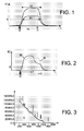
- Te is the time of transit of electrons for a place of interaction given: T2 is the measured time for an energy important and T1 in the case of a pulse of energy weaker.
- a second limitation of methods is the impossibility of dealing with complex impulses, for example due to interactions multiple.
- a double ID interaction is represented in FIG. 2, the curve IS representing an interaction simple. In such a case, the bi-parametric method is default.
- the 2 types of important interactions are the photoelectric effect (the photon is totally absorbed) and the Compton effect (diffusion with deposit of a fraction of energy).
- Simple interactions allow to get a better energy resolution while that double interactions have high probabilities to match reabsorbed Compton photons and therefore to belong to a peak of complete deposit.
- the method according to the invention therefore Rehabilitation, using the estimation previous charge and transit time, the threshold value used for time measurement and amplitude.
- the invention therefore also relates to a spectrometric method with bi-parametric correction adaptive, preferably with the help of digital means.
- New threshold values can be calculated from reference data previously stored.
- the reiteration can take place until at least one difference between two successive values at least one of the specified charges and / or time passed over at least one of the thresholds and / or one of the time intervals is less than a value predetermined.
- the stages of determination of loads can be achieved by integration.
- the signal is advantageously filtered before integration.
- New threshold values can be determined by analytical method, or by experimental calibration or modeling.
- the signal can come from a detector semiconductor, for example a semiconductor detector CdTe or CdZnTe.
- the means to determine the Charges may include one or more integrators.
- Such a device may also include means for filtering the signal or the signals before integration.
- the means to determine the news Threshold values can be programmed to implement an analytical method, or by experimental calibration or modeling.
- a detection device comprises a detector and a device such as as described above.
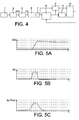
- FIG. 1 A first embodiment of the invention is illustrated in FIG. 1
- the system comprises a detector 1 of the type semiconductor, for example in the field of X or gamma spectrometry.
- a preamplifier 2 charging provides a load Q (t) to a differentiator 4, which allows to obtain a current pulse I (t) from the charge Q (t).
- Figures 5A and 5B show respectively the evolutions in time of I and Q.
- thresholding means therefore allow identify the moments between which the signal is greater than a given threshold value. They produce a logic signal, for example of gate or step type, as shown in Figure 5D.
- This device makes it possible to measure the time spent by the current above a certain threshold S 1 , which allows a measurement or an estimation of the transit time T (FIG. 1) of the electrons.
- Means 14 time-amplitude converter realize this measurement or this estimate of time to from the logic signal provided by means 16 of thresholding.
- these means 14 can be achieved by integrating a constant current during the active state of the logic signal.
- these means 14 can be realized by a pulse counter clock whose frequency is compatible with the desired accuracy.
- a switched integrator 8 integrates the current over this period and therefore provides a signal relating to the corresponding charge. This charge is the integral of the signal on the time T.
- the charge and time information (provided by means 8 and 14) is provided to the calculating means. These means will be able to calculate or determine a new threshold S 2 which will replace the threshold S 1 in the means 16, and which will be better adapted to the pulse to be analyzed.
- the means 10 for calculating threshold can be made, in digital electronics, thanks to a microprocessor or a programmable arithmetic unit.
- the system iterates the process a number enough times to reach a precision desired: at each iteration, a new threshold value.
- the signal has been previously memorized in the storage means 7.
- the system further comprises a lowpass filter 6 shaping.
- this low-pass filter 6 The characteristics of this low-pass filter 6 are determined from the spectral density of the measurement noise (mostly generated by the detector 1 and the preamplifier electronics 2). This spectral density of the noise can be either measured, is theoretically estimated.
- Figure 5C gives an example of the current I (t) after filtering.
- the impulse response of this filter 6 is, according to one embodiment, calculated it compensates for the color of the noise.
- a filter 6 with a finite impulse response feasible in digital electronics thanks for example multi-rate techniques may also be appropriate and is more convenient to achieve.
- the pulse at the output of means 6 can be digitized and stored in storage means 7.
- a first method is called analytic.
- the charge Q of the pulse is estimated and duration T.
- Method by experimental calibration A second method is called “Method by experimental calibration”.
- impulses simulating a detector are sent to the input of the system, with a known load and time (Q, T) pair.
- the domain (Q, T) is then scanned and, for each setting, the threshold value is determined to obtain a correct measurement (the Q and T measured using this threshold are in accordance with the actual Q and T of the pulse ).
- One is then able to "tabulate" the function threshold f (Q, T) on the whole domain.
- a third method is called “Method by modeling”.
- the approach is similar but uses a noisy impulse model that we derive and filter (the impulse response of the filter is known).
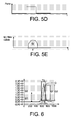
- FIG. 6 illustrates the principle of the invention.
- a first arbitrary threshold S 1 makes it possible to delimit a time interval T 1 during which the intensity I is above the threshold S 1 .
- a first charge Q 1 can then be calculated, which will make it possible to calculate, with the value of T 1 , a new threshold S 2 , from which a new interval T 2 is determined, as well as a new charge Q2, etc. ...
- the invention also relates to a device and a method of spectrometry with multi-parametric correction for recognition of multiple interactions.
- This device has elements similar to those in Figure 4, designated by identical numerical references.
- the signal is then integrated on two periods (from the beginning to the end of pulse number I and beginning at the end of pulse No. II) so as to evaluate the respective contributions of Q1 and Q2.
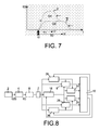
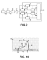
- FIG. 8 gives an exemplary embodiment such a device.
- it includes a second integrator 28, a second means 24 converter time-amplitude, as well as a second and a third thresholding means 26,36 (for example two comparators).
- the three thresholds S 1 , S 2 , S 3 are respectively associated with the thresholding means 16, 26, 36.
- the first two thresholds allow determine the beginning and the end of the first component of the signal.
- the thresholds S 1 and S 3 make it possible to determine the beginning and the end of the second component of the signal.
- the three thresholds S1, S2 and S3 are linked and adjusted by the means 10 after calculation of the charges Q 1 and Q 2 and the intervals T 1 and T 2 associated with these components.
- the means 10 can be programmed according to one of the three methods explained above (analytical method, or by calibration experimental or modeling).
- the reference 46 designates thresholding means
- the reference 48 a integrator
- the reference 44 means time - amplitude converters.
- the first and second thresholds are readjusted by means 10 since the data on charges and durations were calculated, and these readjusted values are reinjected in the thresholding means 16, 46.
- the iterations are repeated until a predetermined convergence threshold is reached.
- a deviation lower than a predetermined value, between two successive thresholds Si and S i + 1 and / or two successive loading quantities Q i and Q i + 1 .
- the invention can also be adapted to different geometries of detectors, particularly non-planar geometry detectors, giving signals more complex forms.
- two thresholds S 1 and S 2 make it possible to identify respectively the beginning and the end of a pulse.
- t 0 and t 1 respectively represent the instants of the interaction in the detector and the arrival of the charges at the anode of the same detector.
- the thresholds S 1 and S 2 define a duration T between the beginning and the end of the pulse.
- the values of Q and T are input into the calculation means 110 which will determine new threshold values S ' 1 and S' 2 of start and end of the pulse. It follows a new load calculation Q ', a new time interval T', in turn entered in the means 10 of calculation.
- a device for the implementation of this The process is illustrated in FIG. 11 and comprises two thresholding devices 116,136 (for example two comparators), a switched differential integrator 118, a time-amplitude converter 114, means 110 of calculation. Possibly two 120,122 filters for setting form of beginning and end of signal can be arranged in the measuring chain.
- filtering can be determined in the following manner.
- the response of the filter is then determined linear transformation of this form into a step, which consists in performing a mathematical operation of deconvolution.
- a switched differential integrator 118 realize the difference of the integrals of the 2 signals incoming between the two start and end dates.
- the invention leads to the determination of a torque (charge Q, duration T) which makes it possible to go back to the energy of the incident photon thanks to a curve calibrated using a calibrated source in energy.
- the resulting Q value is in principle proportional to the energy for a given time T.
- a method implementing the determination of photon energy as a function of the measured load and rise time is described in FR - 2 738 919.
- the means 10, 110 of calculation can memorize a correspondence table that allows, at course of subsequent measures, to know the threshold at apply to ascend, by iteration, to the load representative of the interaction phenomenon.
Landscapes
- Physics & Mathematics (AREA)
- Health & Medical Sciences (AREA)
- Life Sciences & Earth Sciences (AREA)
- General Physics & Mathematics (AREA)
- High Energy & Nuclear Physics (AREA)
- Molecular Biology (AREA)
- Spectroscopy & Molecular Physics (AREA)
- Measurement Of Radiation (AREA)
- Optical Transform (AREA)
- Investigating, Analyzing Materials By Fluorescence Or Luminescence (AREA)
- Measurement Of The Respiration, Hearing Ability, Form, And Blood Characteristics Of Living Organisms (AREA)
Abstract
L'invention concerne un procédé
d'exploitation d'un signal fourni par un détecteur,
dans lequel :
Description
L'invention concerne le domaine de la spectrométrie, notamment X ou gamma à l'aide d'un détecteur semi-conducteur.The invention relates to the field of spectrometry, especially X or gamma using a semiconductor detector.
De tels détecteurs comportent souvent des défauts de collection des porteurs de charge.Such detectors often include collection defects of the charge carriers.
Une spectrométrie du rayonnement incident permet de déterminer la quantité de porteurs de charges créés par l'interaction du photon, par exemple X ou gamma.An incident radiation spectrometry allows to determine the quantity of load carriers created by the interaction of the photon, for example X or gamma.
A cette fin, on applique un champ électrique au matériau détecteur à l'aide d'électrodes de manière à drainer ces charges et induire un signal électrique d'amplitude proportionnel à leur quantité. Malheureusement, la mesure de cette quantité de porteurs est rendue difficile par les propriétés de transport imparfaites du semi-conducteur : en effet, une partie des charges ne parviennent pas jusqu'aux électrodes. C'est le problème de collection incomplète.For this purpose, a field is applied electrical to detector material using electrodes in order to drain these charges and induce a signal electrical amplitude proportional to their quantity. Unfortunately, measuring this amount of carriers is made difficult by the properties of imperfect transport of the semiconductor: indeed, some of the charges do not reach electrodes. This is the problem of incomplete collection.
En outre, en particulier dans le cas du CdZnTe, les propriétés de transport des trous sont particulièrement mauvaises tandis que celles des électrons sont bonnes.In addition, particularly in the case of CdZnTe, the transport properties of the holes are particularly bad while those of electrons are good.
On mesure alors un signal qui correspond au transit des électrons dans le matériau. We then measure a signal that corresponds to transit of electrons in the material.
Une des techniques proposées pour corriger cette correction incomplète, due au mauvais transport des trous, est d'effectuer un traitement électronique du signal mesuré.One of the proposed techniques to correct this incomplete correction, due to bad transport holes, is to perform electronic processing the measured signal.
En plus de la mesure d'amplitude mesurant la charge totale collectée, la mesure d'un ou plusieurs autres paramètres sur la forme du signal électrique obtenu (par exemple son temps de montée) permet en particulier de remonter au lieu d'interaction du photon dans le milieu semi-conducteur.In addition to measuring amplitude measuring the total charge collected, the measurement of one or more other parameters on the shape of the electrical signal obtained (eg its rise time) allows in particular to go back to the place of interaction of the photon in the semiconductor medium.
Grâce à un étalonnage de l'efficacité de collecte en fonction du lieu d'interaction, on peut alors déterminer la charge réellement déposée par le photon.Thanks to a calibration of the efficiency of collection according to the place of interaction, one can then determine the actual load deposited by the photon.
C'est la méthode bi-paramétrique « électrons » décrite dans le document FR - 2738919.This is the bi-parametric method "Electrons" described in the document FR - 2738919.
Le temps de montée peut être déterminé de différentes manières.The rise time can be determined from different ways.
Une première méthode consiste à mesurer le temps écoulé entre le passage du signal de charge par un seuil de déclenchement (réalisé par un comparateur) déterminant le début de l'impulsion et son arrivée à son amplitude maximale (mesurée grâce à un détecteur de crête).One method is to measure the time elapsed between the passage of the charge signal by a trigger threshold (made by a comparator) determining the beginning of the impulse and its arrival at its maximum amplitude (measured using a Crest).
Une autre méthode consiste à travailler sur le signal de courant (obtenu à l'aide d'un circuit dérivateur). On mesure alors le temps écoulé entre le passage du courant au-dessus d'une valeur seuil et son retour en dessous de ce même seuil. Cette méthode a l'avantage d'être précise et facile à réaliser puisqu'elle utilise un comparateur et un convertisseur temps-amplitude.Another method is to work on the current signal (obtained using a circuit differentiator). The time elapsed between the current flow above a threshold value and its return below this same threshold. This method has the advantage of being precise and easy to achieve since it uses a comparator and a converter time-amplitude.
Ces méthodes ont toutefois des limitations, en particulier en ce qui concerne la linéarité des mesures sur une dynamique de signaux importante. De plus, on pourra les paramétrer de manière à minimiser le bruit uniquement autour de certaines valeurs de signal.These methods, however, have limitations, especially as regards the linearity of measurements on a significant signal dynamics. Of more, we can set them to minimize noise only around certain values of signal.
La figure 1, qui montre deux impulsions de courant, donne une explication du problème dans le cas de la deuxième méthode exposée ci-dessus.Figure 1, which shows two pulses of current, gives an explanation of the problem in the case of the second method set out above.
Sur cette figure, Te est le temps de transit des électrons pour un lieu d'interaction donné : T2 est le temps mesuré pour une énergie importante et T1 dans le cas d'une impulsion d'énergie plus faible.In this figure, Te is the time of transit of electrons for a place of interaction given: T2 is the measured time for an energy important and T1 in the case of a pulse of energy weaker.
Du fait des constantes de temps du système (imposées par la nécessité de filtrer le bruit) on a T1<T2<Te.Due to system time constants (imposed by the need to filter noise) we have T1 <T2 <Te.
On obtiendra donc des temps mesurés différents entre eux et différents du temps de transit des électrons, qui est en principe unique.We will therefore obtain measured times different from each other and different from transit time electrons, which is in principle unique.
De plus, en terme de bruit, il y aura une position de seuil optimum (en général, là où la pente est maximale). Or, cette position ne pourra être respectée que pour une certaine valeur d'amplitude.Moreover, in terms of noise, there will be a optimum threshold position (usually where the slope is maximum). However, this position can not be respected only for a certain amplitude value.
Il y a, en fait, un compromis à faire entre dynamique et bruit : le filtrage limite le bruit mais réduit la stabilité des performances sur une grande dynamique. There is, in fact, a trade-off between dynamic and noise: filtering limits noise but reduces stability of performance on a large dynamic.
Une deuxième limitation des méthodes classiques est l'impossibilité de traiter des impulsions complexes, dues par exemple aux interactions multiples.A second limitation of methods is the impossibility of dealing with complex impulses, for example due to interactions multiple.
Une interaction double ID est représentée en figure 2, la courbe IS représentant une interaction simple. Dans un tel cas, la méthode bi-paramétrique est mise en défaut.A double ID interaction is represented in FIG. 2, the curve IS representing an interaction simple. In such a case, the bi-parametric method is default.
Deux photons incidents d'énergies différentes vont donner le couple amplitude/temps mesuré.Two incident photons of energies different will give the amplitude / time couple measured.
La méthode bi-paramétrique classique échoue donc à identifier les énergies.The classical bi-parametric method fails therefore to identify the energies.
Il serait intéressant d'identifier ces cas d'impulsions multiples pour éviter de dégrader les spectres.It would be interesting to identify these cases multiple impulses to avoid degrading spectra.
De plus, la possibilité de séparer les contributions des 2 nuages d'électrons est intéressante pour reconnaítre les interactions simples des interactions multiples et identifier plus facilement les pics sur un continuum Compton.Moreover, the possibility of separating contributions of the 2 electron clouds is interesting to recognize the simple interactions of multiple interactions and identify more easily peaks on a Compton continuum.
En effet, dans la gamme d'énergie 100keV - 1000keV, les 2 types d'interactions importants sont l'effet photoélectrique (le photon est totalement absorbé) et l'effet Compton (diffusion avec dépôt d'une fraction d'énergie).Indeed, in the 100keV energy range - 1000keV, the 2 types of important interactions are the photoelectric effect (the photon is totally absorbed) and the Compton effect (diffusion with deposit of a fraction of energy).
Les interactions simples permettent d'obtenir une meilleure résolution en énergie tandis que les interactions doubles ont de fortes probabilités de correspondre à des photons Compton réabsorbés et donc d'appartenir à un pic de dépôt complet. Simple interactions allow to get a better energy resolution while that double interactions have high probabilities to match reabsorbed Compton photons and therefore to belong to a peak of complete deposit.
La combinaison des deux informations offre la possibilité de réduire le continuum Compton tout en améliorant la résolution.The combination of both information offers the possibility of reducing the Compton continuum while improving the resolution.
Enfin une troisième limitation est la suivante. Tous les détecteurs ne fournissent pas un courant de forme « plate ». Pour les géométries couramment utilisées, le courant croít lorsque les électrons se rapprochent de l'anode. Il est donc nécessaire d'appliquer un seuil de fin d'impulsion plus haut que le seuil de début d'impulsion pour optimiser la performance. La mesure n'en est donc pas facilitée.Finally a third limitation is the next. All detectors do not provide a "flat" form current. For geometries commonly used, the current increases when the electrons are getting closer to the anode. It is therefore necessary to apply a threshold of end of impulse more higher than the impulse start threshold to optimize the performance. The measurement is therefore not facilitated.
L'invention concerne d'abord un procédé
d'exploitation d'un signal, notamment en courant,
fourni par un détecteur, dans lequel :
Selon un mode de réalisation particulier,
un procédé selon l'invention comporte en outre les
étapes suivantes :
L'invention concerne également un procédé
d'exploitation d'un signal, notamment en courant,fourni
par un détecteur, dans lequel :
L'invention concerne également un procédé
d'exploitation d'un signal, notamment en courant,
fourni par un détecteur, comportant une première
composante superposée à une deuxième composante, dans
lequel :
Quel que soit le mode de réalisation envisagé, le procédé selon l'invention met donc en oeuvre une réadaptation, à l'aide de l'estimation précédente de la charge et du temps de transit, de la valeur du seuil servant à la mesure de temps et d'amplitude.Whatever the embodiment envisaged, the method according to the invention therefore Rehabilitation, using the estimation previous charge and transit time, the threshold value used for time measurement and amplitude.
L'invention concerne donc également un procédé de spectrométrie avec correction bi-paramétrique adaptative, de préférence à l'aide de moyens numériques.The invention therefore also relates to a spectrometric method with bi-parametric correction adaptive, preferably with the help of digital means.
Les nouvelles valeurs de seuils peuvent être calculées à partir de données de référence préalablement mémorisées.New threshold values can be calculated from reference data previously stored.
La réitération peut avoir lieu jusqu'à ce qu'au moins un écart entre deux valeurs successives d'au moins une des charges déterminées et/ou du temps passé au-dessus d'au moins un des seuils et/ou d'un des intervalles de temps soit inférieur à une valeur prédéterminée.The reiteration can take place until at least one difference between two successive values at least one of the specified charges and / or time passed over at least one of the thresholds and / or one of the time intervals is less than a value predetermined.
Les étapes de détermination de charges peuvent être réalisée par intégration.The stages of determination of loads can be achieved by integration.
Le signal est avantageusement filtré avant intégration.The signal is advantageously filtered before integration.
Les nouvelles valeurs de seuils peuvent être déterminées par procédé analytique, ou par calibration expérimentale ou par modélisation.New threshold values can be determined by analytical method, or by experimental calibration or modeling.
Le signal peut être issu d'un détecteur à semi-conducteur, par exemple un détecteur à semi-conducteur CdTe ou CdZnTe.The signal can come from a detector semiconductor, for example a semiconductor detector CdTe or CdZnTe.
L'invention concerne également un
dispositif d'exploitation d'un signal fourni par un
détecteur, comportant :
Un tel dispositif peut en outre comporter:
Selon un autre aspect, l'invention concerne
également un dispositif d'exploitation d'un signal
fourni par un détecteur, comportant:
Elle concerne aussi un dispositif
d'exploitation d'un signal fourni par un détecteur,
comportant : une première composante superposée à une
deuxième composante, dans lequel :
Les moyens pour déterminer la ou les charges peuvent comporter un ou plusieurs intégrateur.The means to determine the Charges may include one or more integrators.
Un tel dispositif selon l'un des modes de réalisation ci-dessus peut comporter en outre des moyens pour filtrer le signal ou les signaux avant intégration.Such a device according to one of the modes of above may also include means for filtering the signal or the signals before integration.
Les moyens pour déterminer les nouvelles valeurs de seuil peuvent mettre être programmés pour mettre en oeuvre un procédé analytique, ou par calibration expérimentale ou par modélisation.The means to determine the news Threshold values can be programmed to implement an analytical method, or by experimental calibration or modeling.
Un dispositif de détection selon l'invention comporte un détecteur et un dispositif tel que décrit ci-dessus.A detection device according to the invention comprises a detector and a device such as as described above.
- Les figures 1 et 2 illustrent des cas de superposition d'impulsions ;Figures 1 and 2 illustrate cases of superposition of pulses;
- la figure 3 représente un spectre obtenu, avec fond Compton ;Figure 3 shows a spectrum obtained, with Compton background;
- la figure 4 représente un premier exemple d'un dispositif selon l'invention ;FIG. 4 represents a first example of a device according to the invention;
- les figures 5A-5E représentent un ensemble de signaux de charge et d'intensité en fonction du temps ;Figures 5A-5E show a set of load and intensity signals in function of time;
- la figure 6 représente une impulsion et le signal intégré correspondant, avec le positionnement d'un seuil, et la mesure d'une valeur de charge ;FIG. 6 represents an impulse and the corresponding integrated signal, with the positioning a threshold, and the measurement of a charge value;
- la figure 7 représente schématiquement un procédé de mesure selon l'invention, dans le cas d'une impulsion double ; Figure 7 shows schematically a measuring method according to the invention, in the case a double pulse;
- les figures 8 et 9 représentent d'autres exemples de dispositifs selon l'invention ;Figures 8 and 9 show other examples of devices according to the invention;
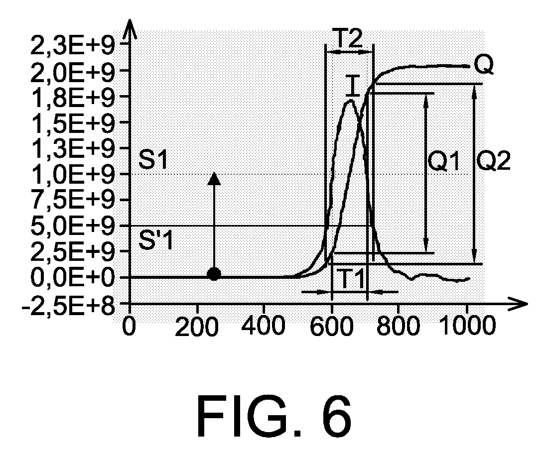
- la figure 10 représente schématiquement un procédé de mesure selon l'invention, dans le cas d'une impulsion issue d'un détecteur à géométrie non plane ;Figure 10 shows schematically a measuring method according to the invention, in the case a pulse from a non-geometry detector plane ;
- la figure 11 représente encore un autre dispositif selon l'invention ;Figure 11 represents yet another device according to the invention;
- la figure 12 représente un intégrateur différentiel.Figure 12 shows an integrator differential.
Un premier mode de réalisation de l'invention est illustré en figure 4.A first embodiment of the invention is illustrated in FIG.
Le système comporte un détecteur 1 de type
à semi-conducteur, par exemple dans le domaine de la
spectrométrie X ou gamma.The system comprises a
Un préamplificateur 2 de charge, fournit
une charge Q (t) à un dérivateur 4, qui permet
d'obtenir une impulsion de courant I (t) à partir de la
charge Q (t).A
Les figures 5A et 5B représentent respectivement les évolutions en temps de I et de Q.Figures 5A and 5B show respectively the evolutions in time of I and Q.
Il comporte en outre des moyens 16 de
seuillage, de type comparateur.It also includes
Ces moyens de seuillage permettent donc d'identifier les instants entre lesquels le signal est supérieur à une valeur seuil donnée. Ils produisent un signal logique, par exemple de type porte ou échelon, tel qu'illustré sur la figure 5D. These thresholding means therefore allow identify the moments between which the signal is greater than a given threshold value. They produce a logic signal, for example of gate or step type, as shown in Figure 5D.
Ce dispositif permet de mesurer le temps que passe le courant au dessus d'un certain seuil S1, ce qui permet une mesure ou une estimation du temps de transit T (figure 1) des électrons.This device makes it possible to measure the time spent by the current above a certain threshold S 1 , which allows a measurement or an estimation of the transit time T (FIG. 1) of the electrons.
Des moyens 14 convertisseur temps-amplitude
réalisent cette mesure ou cette estimation de temps à
partir du signal logique fourni par les moyens 16 de
seuillage.Means 14 time-amplitude converter
realize this measurement or this estimate of time to
from the logic signal provided by
En électronique analogique, ces moyens 14 peuvent être réalisés en intégrant un courant constant durant l'état actif du signal logique.In analog electronics, these means 14 can be achieved by integrating a constant current during the active state of the logic signal.
En électronique numérique, ces moyens 14 peuvent être réalisés par un compteur d'impulsions d'horloge dont la fréquence est compatible avec la précision désirée.In digital electronics, these means 14 can be realized by a pulse counter clock whose frequency is compatible with the desired accuracy.
Un intégrateur commuté 8 intègre le courant
sur cette période et fournit donc un signal relatif à
la charge correspondante. Cette charge est l'intégrale
du signal sur le temps T.A switched
Les informations relatives à la charge et
au temps (fournies par les moyens 8 et 14) sont
fournies aux moyens 10 de calculs. Ces moyens vont
pouvoir calculer ou déterminer un nouveau seuil S2 qui
va remplacer le seuil S1 dans les moyens 16, et qui
sera mieux adapté à l'impulsion à analyser.The charge and time information (provided by
Les moyens 10 de calcul de seuil peuvent être réalisés, en électronique numérique, grâce à un microprocesseur ou une unité arithmétique programmable.The means 10 for calculating threshold can be made, in digital electronics, thanks to a microprocessor or a programmable arithmetic unit.
On met donc en oeuvre, pour mesurer l'amplitude, une dérivation du signal de charge Q (t), réintégré ensuite (par les moyens 8) sur la durée mesurée T de l'impulsion, après seuillage.So we implement, to measure the amplitude, a derivation of the charge signal Q (t), then reintegrated (by the means 8) over the duration measured T of the pulse, after thresholding.
Le système itère le processus un nombre suffisant de fois pour atteindre une précision désirée : à chaque itération, on utilise une nouvelle valeur de seuil. Le signal a été préalablement mémorisé dans les moyens de mémorisation 7.The system iterates the process a number enough times to reach a precision desired: at each iteration, a new threshold value. The signal has been previously memorized in the storage means 7.
De préférence, le système comporte en outre
un filtre passe-bas 6 de mise en forme.Preferably, the system further comprises
a
Les caractéristiques de ce filtre passe-bas
6 sont déterminées d'après la densité spectrale du
bruit de mesure (généré en majeure partie par le
détecteur 1 et l'électronique 2 de préamplification).
Cette densité spectrale du bruit peut être soit
mesurée, soit estimée théoriquement.The characteristics of this low-
La figure 5C donne un exemple du courant I(t) après filtrage.Figure 5C gives an example of the current I (t) after filtering.
La réponse impulsionnelle de ce filtre 6
est, selon un mode de réalisation, calculée de manière
à ce qu'elle compense la coloration du bruit.The impulse response of this
Un filtre 6 à réponse impulsionnelle finie
réalisable en électronique numérique, grâce par exemple
à des techniques multi-cadences peut aussi convenir et
est plus commode à réaliser.A
Par ailleurs, dans une structure rebouclée
comme celle de la figure 4, l'impulsion en sortie des
moyens 6 peut être numérisée et mémorisée dans des
moyens de mémorisation 7.Moreover, in a looped structure
like that of Figure 4, the pulse at the output of
On peut citer différentes méthodes pour déterminer comment les moyens 10 peuvent calculer le nouveau seuil. We can mention different methods for determine how the means 10 can calculate the new threshold.
Une première méthode est dite analytique. On estime la charge Q de l'impulsion et sa durée T. S1 on suppose que l'impulsion de courant est de forme carrée, le courant moyen I=Q/T donne une bonne estimation du niveau haut de l'impulsion. Pour un filtre de réponse impulsionnelle symétrique, placer le seuil à I/2=Q/2T permettra donc de se caler sur la pente maximale. On affine ainsi la mesure.A first method is called analytic. The charge Q of the pulse is estimated and duration T. S 1 it is assumed that the current pulse is square, the average current I = Q / T gives a good estimate of the high level of the pulse. For a symmetric impulse response filter, setting the threshold to I / 2 = Q / 2T will allow you to adjust to the maximum slope. This refines the measurement.
Une deuxième méthode est dite « Méthode par calibration expérimentale ».A second method is called "Method by experimental calibration ".
A l'aide d'un générateur, on envoie en
entrée du système des impulsions simulant un détecteur,
avec un couple charge et temps (Q,T) connu. On balaye
alors le domaine (Q,T) et, pour chaque réglage, on
détermine la valeur de seuil permettant d'obtenir une
mesure correcte (les Q et T mesurés grâce à ce seuil
sont conformes aux Q et T réels de l'impulsion). On est
alors capable de « tabuler » la fonction seuil=f(Q,T)
sur l'ensemble du domaine. Une mesure de Qm et Tm sur un
signal réel, fournis par les moyens 8,14, permet
ensuite de déterminer un seuil S=f(Qm, Tm).With the help of a generator, impulses simulating a detector are sent to the input of the system, with a known load and time (Q, T) pair. The domain (Q, T) is then scanned and, for each setting, the threshold value is determined to obtain a correct measurement (the Q and T measured using this threshold are in accordance with the actual Q and T of the pulse ). One is then able to "tabulate" the function threshold = f (Q, T) on the whole domain. A measurement of Q m and T m on a real signal, provided by the
Une troisième méthode est dite « Méthode par modélisation ». La démarche est similaire mais utilise un modèle d'impulsion bruitée que l'on dérive et filtre (la réponse impulsionnelle du filtre est connue).A third method is called "Method by modeling ". The approach is similar but uses a noisy impulse model that we derive and filter (the impulse response of the filter is known).
On détermine alors, par le calcul, la position de seuil qui permet la meilleure estimation de Q et T, par exemple à l'aide du critère du MAP (Maximum A Posteriori). Il s'agit d'une approche probabiliste qui consiste à placer le seuil à un niveau tel que l'on obtient une estimation de Q et de T avec une probabilité maximale.We then determine, by calculation, the threshold position that allows the best estimate of Q and T, for example using the MAP criterion (Maximum A Posteriori). This is a probabilistic approach which consists in placing the threshold at a level such that gets an estimate of Q and T with a maximum probability.
Quelle que soit la méthode retenue, on peut
numériser le signal soit juste avant le filtrage, soit
dès la sortie du préamplificateur 2.Whichever method is chosen, one can
digitize the signal either just before filtering or
at the output of the
La figure 6 illustre le principe de l'invention. Un premier seuil S1 arbitraire permet de délimiter un intervalle de temps T1 au cours duquel l'intensité I se situe au-dessus du seuil S1. Une première charge Q1 peut alors être calculée, qui va permettre de calculer, avec la valeur de T1, un nouveau seuil S2, à partir duquel un nouvel intervalle T2 est déterminé, ainsi qu'une nouvelle charge Q2, etc....Figure 6 illustrates the principle of the invention. A first arbitrary threshold S 1 makes it possible to delimit a time interval T 1 during which the intensity I is above the threshold S 1 . A first charge Q 1 can then be calculated, which will make it possible to calculate, with the value of T 1 , a new threshold S 2 , from which a new interval T 2 is determined, as well as a new charge Q2, etc. ...
Comme critère de convergence, et donc d'arrêt des itérations, on peut choisir un écart, inférieur à une valeur prédéterminée, entre deux seuils successifs Si et Si+1 et/ou deux quantités de charges successives Qi et Qi+1.As criterion of convergence, and therefore of stop of the iterations, it is possible to choose a difference, smaller than a predetermined value, between two successive thresholds S i and S i + 1 and / or two successive charge quantities Q i and Q i + 1 .
L'invention concerne également un dispositif et un procédé de spectrométrie avec correction multi-paramétrique pour reconnaissance des interactions multiples.The invention also relates to a device and a method of spectrometry with multi-parametric correction for recognition of multiple interactions.
Un tel dispositif est illustré sur la figure 8.Such a device is illustrated on the figure 8.
Ce dispositif comporte des éléments similaires à ceux de la figure 4, désignés par des références numériques identiques.This device has elements similar to those in Figure 4, designated by identical numerical references.
Mais on applique ici plusieurs seuillages, afin de séparer les différentes composantes des impulsions. But here we apply several thresholds, in order to separate the different components of pulses.
Ce système permet notamment de traiter le cas de deux composantes (figure 7): la composante I, de charge Q1 et de durée T1 et la composante II, de charge Q2 et de durée T2.This system makes it possible in particular to treat the case of two components (Figure 7): the I component of charge Q1 and duration T1 and component II, charge Q2 and duration T2.
Pour décomposer l'impulsion, on peut par exemple appliquer 3 seuils : un premier seuil (S1) pour détecter l'instant d'interaction (t0), correspondant au début de l'impulsion ; un deuxième seuil (S2) pour détecter la fin de la composante n°I (t1) et un troisième (S3) pour la fin de la composante n°II (t2).To decompose the pulse, one can for example apply 3 thresholds: a first threshold (S1) to detect the moment of interaction (t 0 ), corresponding to the beginning of the pulse; a second threshold (S2) for detecting the end of the component No. I (t 1 ) and a third (S3) for the end of the component No. II (t 2 ).
Le signal est ensuite intégré sur deux périodes (du début à la fin de l'impulsion n°I et du début à la fin de l'impulsion n°II) de manière à évaluer les contributions respectives de Q1 et Q2.The signal is then integrated on two periods (from the beginning to the end of pulse number I and beginning at the end of pulse No. II) so as to evaluate the respective contributions of Q1 and Q2.
L'intégration sur T2 donne ainsi par exemple Q1+Q2 tandis que l'intégration sur T1 donnera Q1+Q2.T1/T2.The integration on T2 thus gives by example Q1 + Q2 while integration on T1 will give Q1 + Q2.T1 / T2.
A l'aide de ces 2 données ou équations, on obtient les 2 inconnues Q1 et Q2.Using these 2 data or equations, we gets the 2 unknowns Q1 and Q2.
La figure 8 donne un exemple de réalisation
d'un tel dispositif. Outre les éléments déjà décrits en
liaison avec la figure 4, et pour cette raison désignés
par des références identiques, il comporte un deuxième
intégrateur 28, un deuxième moyen 24 convertisseur
temps-amplitude, ainsi qu'un deuxième et un troisième
moyens de seuillage 26,36 (par exemple deux
comparateurs).FIG. 8 gives an exemplary embodiment
such a device. In addition to the elements already described in
connection with Figure 4, and for this reason designated
by identical references, it includes a
Les trois seuils S1, S2, S3 sont respectivement associés aux moyens de seuillage 16,26,36. The three thresholds S 1 , S 2 , S 3 are respectively associated with the thresholding means 16, 26, 36.
Les deux premiers seuils permettent de déterminer le début et la fin de la première composante du signal.The first two thresholds allow determine the beginning and the end of the first component of the signal.
Les seuils S1 et S3 permettent de déterminer le début et la fin de la deuxième composante du signal.The thresholds S 1 and S 3 make it possible to determine the beginning and the end of the second component of the signal.
Les 3 seuils S1, S2 et S3 sont liés et
ajustés par les moyens 10 après calcul des charges Q1
et Q2 et des intervalles T1 et T2 associés à ces
composantes.The three thresholds S1, S2 and S3 are linked and adjusted by the
Là encore, les moyens 10 peuvent être
programmés selon l'une des trois méthodes expliquées
ci-dessus (méthode analytique, ou par calibration
expérimentale ou par modélisation).Again, the
Il est également possible de traiter un signal tel que celui de la figure 7 avec seulement deux seuils. Dans ce cas, le dispositif est par exemple celui de la figure 9, avec deux branchements symétriques similaires à la chaíne de traitement de celle de la figure 4.It is also possible to treat a signal like that of Figure 7 with only two thresholds. In this case, the device is for example that of Figure 9, with two connections symmetrical similar to the processing chain of that of Figure 4.
Sur cette figure, la référence 46 désigne
des moyens de seuillage, la référence 48 un
intégrateur, et la référence 44 des moyens
convertisseurs temps - amplitude.In this figure, the
Le premier et le deuxième seuils sont
réajustés à l'aide des moyens 10 dès lors que les
données relatives aux charges et aux durées ont été
calculées, et ces valeurs réajustées sont réinjectées
dans les moyens de seuillage 16, 46.The first and second thresholds are
readjusted by
Les itérations sont répétées jusqu'à atteinte d'un seuil de convergence prédéterminé. Là encore, on peut retenir, comme critère de convergence, et donc d'arrêt des itérations, un écart, inférieur à une valeur prédéterminée, entre deux seuils successifs Si et Si+1 et/ou deux quantités de charges successives Qi et Qi+1.The iterations are repeated until a predetermined convergence threshold is reached. Here again, it is possible to retain, as criterion of convergence, and thus of stop of the iterations, a deviation, lower than a predetermined value, between two successive thresholds Si and S i + 1 and / or two successive loading quantities Q i and Q i + 1 .
L'invention peut également être adaptée aux différentes géométries de détecteurs, notamment de détecteurs à géométrie non plane, donnant des signaux de formes plus complexe.The invention can also be adapted to different geometries of detectors, particularly non-planar geometry detectors, giving signals more complex forms.
Dans ce cas, on traite différemment le début et la fin de l'impulsion, avec une valeur de seuil de début et une valeur de seuil de fin qui sont différentes l'une de l'autre.In this case, the beginning and end of the impulse, with a value of start threshold and an end threshold value that are different from each other.
On adopte aussi, préférentiellement, un filtrage préalable de l'impulsion pour obtenir un signal à flancs plus raides, de manière à optimiser la précision de la mesure de temps.We also adopt, preferentially, a pre-filtering the pulse to get a signal with steeper flanks, so as to optimize the accuracy of time measurement.
Comme illustré sur la figure 10, deux seuils S1 et S2 permettent d'identifier respectivement le début et la fin d'une impulsion. t0 et t1 représentent respectivement les instants de l'interaction dans le détecteur et d'arrivée des charges à l'anode de ce même détecteur.As illustrated in FIG. 10, two thresholds S 1 and S 2 make it possible to identify respectively the beginning and the end of a pulse. t 0 and t 1 respectively represent the instants of the interaction in the detector and the arrival of the charges at the anode of the same detector.
Les seuils S1 et S2 définissent une durée T entre le début et la fin de l'impulsion.The thresholds S 1 and S 2 define a duration T between the beginning and the end of the pulse.
La charge Q correspondant à la différence entre les intégrales de la courbe filtrée (de 0 à T2) et la courbe réelle (de 0 à T1) est calculée (voir formule de la page suivante).The charge Q corresponding to the difference between the integrals of the filtered curve (from 0 to T2) and the real curve (from 0 to T1) is calculated (see formula on the next page).
Les valeurs de Q et T sont entrées dans les
moyens 110 de calcul qui vont déterminer de nouvelles
valeurs de seuil S'1 et S'2 de début et de fin
d'impulsion. Il s'ensuit un nouveau calcul de charge
Q', un nouvel intervalle de temps T', à leur tour
entrés dans les moyens 10 de calcul.The values of Q and T are input into the calculation means 110 which will determine new threshold values S ' 1 and S' 2 of start and end of the pulse. It follows a new load calculation Q ', a new time interval T', in turn entered in the
Les itérations sont répétées jusqu'à atteinte d'un seuil de convergence prédéterminé.Iterations are repeated until reaching a predetermined convergence threshold.
Un dispositif pour la mise en oeuvre de ce
procédé est illustrée en figure 11 et comporte deux
dispositifs 116,136 de seuillage (par exemple deux
comparateurs), un intégrateur différentiel commuté 118,
un convertisseur 114 temps-amplitude, des moyens 110 de
calcul. Eventuellement deux filtres 120,122 de mise en
forme de début et de fin de signal peuvent être
disposés dans la chaíne de mesure.A device for the implementation of this
The process is illustrated in FIG. 11 and comprises two
thresholding devices 116,136 (for example two
comparators), a switched
Concrètement, le filtrage peut être déterminé de la manière suivante.In concrete terms, filtering can be determined in the following manner.
On établit d'abord un modèle de la forme du courant détecteur au moment de la transition (ce qui peut être fait sous forme numérique ou sous forme analytique, par une équation différentielle par exemple).We first establish a model of the shape of the detector current at the time of transition (which can be done numerically or in form analytically, by a differential equation example).
On détermine ensuite la réponse du filtre linéaire transformant cette forme en un échelon, ce qui consiste à réaliser une opération mathématique de déconvolution.The response of the filter is then determined linear transformation of this form into a step, which consists in performing a mathematical operation of deconvolution.
Un intégrateur différentiel commuté 118
réalise la différence des intégrales des 2 signaux
entrants entre les deux dates de début et fin.A switched
Il peut être réalisé analogiquement de la
manière illustrée en figure 12 à l'aide d'un
amplificateur 150 à entrée et sortie différentielle et
de deux capacités 152, 154 montées comme indiqué sur la
figure.It can be done analogically from the
illustrated in Figure 12 using a
Le calcul réalisé correspond à la formule :

Quel que soit le mode de réalisation envisagé, l'invention aboutit à la détermination d'un couple (charge Q, durée T) qui permet de remonter à l'énergie du photon incident grâce à une courbe d'étalonnage établie à l'aide d'une source calibrée en énergie. La valeur de Q résultante est en principe proportionnelle à l'énergie pour un temps T donné.Whatever the embodiment envisaged, the invention leads to the determination of a torque (charge Q, duration T) which makes it possible to go back to the energy of the incident photon thanks to a curve calibrated using a calibrated source in energy. The resulting Q value is in principle proportional to the energy for a given time T.
Un procédé mettant en oeuvre la détermination de l'énergie des photons en fonction de la charge et du temps de montée mesurés est décrit dans FR - 2 738 919.A method implementing the determination of photon energy as a function of the measured load and rise time is described in FR - 2 738 919.
Les moyens 10, 110 de calcul peuvent mémoriser une table de correspondance qui permet, au cours des mesures ultérieures, de connaítre le seuil à appliquer pour remonter, par itération, à la charge représentative du phénomène d'interaction.The means 10, 110 of calculation can memorize a correspondence table that allows, at course of subsequent measures, to know the threshold at apply to ascend, by iteration, to the load representative of the interaction phenomenon.
Pour une charge Q mesurée et un temps T
obtenu, par exemple par comparaison du signal avec un
seuil S, on recherche dans la table ou dans les moyens
10, 110 le couple (Q, T) et on obtient le seuil S'
correspondant, lui-même réinjecté comme valeur de seuil
dans le comparateur etc.For a measured Q load and a T time
obtained, for example by comparing the signal with a
threshold S, we look in the table or in the
Claims (21)
Applications Claiming Priority (2)
| Application Number | Priority Date | Filing Date | Title |
|---|---|---|---|
| FR0450627 | 2004-03-31 | ||
| FR0450627A FR2868545B1 (en) | 2004-03-31 | 2004-03-31 | SPECTRA ACQUISITION SYSTEM WITH INTEGRATOR WITH THRESHOLD ADAPTATION. |
Publications (2)
| Publication Number | Publication Date |
|---|---|
| EP1598680A2 true EP1598680A2 (en) | 2005-11-23 |
| EP1598680A3 EP1598680A3 (en) | 2006-02-15 |
Family
ID=34939086
Family Applications (1)
| Application Number | Title | Priority Date | Filing Date |
|---|---|---|---|
| EP05102496A Withdrawn EP1598680A3 (en) | 2004-03-31 | 2005-03-30 | System for acquisition of spectra with an integrator having an adaptive threshold |
Country Status (3)
| Country | Link |
|---|---|
| US (1) | US7345285B2 (en) |
| EP (1) | EP1598680A3 (en) |
| FR (1) | FR2868545B1 (en) |
Cited By (1)
| Publication number | Priority date | Publication date | Assignee | Title |
|---|---|---|---|---|
| WO2011042383A1 (en) | 2009-10-07 | 2011-04-14 | Commissariat à l'énergie atomique et aux énergies alternatives | Method for processing data from an ionizing-radiation detector |
Families Citing this family (6)
| Publication number | Priority date | Publication date | Assignee | Title |
|---|---|---|---|---|
| DE102008048306B4 (en) | 2008-09-22 | 2016-06-09 | Siemens Healthcare Gmbh | Method for the detection of X-ray radiation and X-ray system |
| US8890082B2 (en) | 2009-05-19 | 2014-11-18 | Kromek Limited | Radiation detection |
| FR2977328B1 (en) | 2011-07-01 | 2013-08-02 | Commissariat Energie Atomique | IONIZING RADIATION DETECTION DEVICE HAVING AN IMPROVED SPECTROMETRIC RESPONSE RESPONSE SEMICONDUCTOR SENSOR |
| FR3058230B1 (en) * | 2016-10-27 | 2019-03-15 | Detection Technology Sas | SPECTROMETRY DEVICE |
| CN111279222B (en) * | 2017-10-30 | 2023-07-28 | 深圳源光科技有限公司 | LIDAR detector with high temporal resolution |
| CN116745650A (en) | 2021-01-27 | 2023-09-12 | 株式会社岛津制作所 | Signal processing device for X-ray analysis |
Family Cites Families (5)
| Publication number | Priority date | Publication date | Assignee | Title |
|---|---|---|---|---|
| US4543530A (en) | 1982-08-11 | 1985-09-24 | Del Norte Technology, Inc. | Methods of and means for determining the time-center of pulses |
| FR2738693B1 (en) * | 1995-09-12 | 1997-10-10 | Commissariat Energie Atomique | PULSE PROCESSING SYSTEM ARISING FROM THE INTERACTION OF A GAMMA PARTICLE WITH A CDTE RADIATION DETECTOR |
| FR2738919B1 (en) * | 1995-09-15 | 1997-10-17 | Commissariat Energie Atomique | METHOD AND DEVICE FOR THE CORRECTION OF SPECTROMETRIC MEASUREMENT IN THE FIELD OF GAMMA PHOTON DETECTION |
| FR2769099B1 (en) | 1997-10-01 | 1999-11-05 | Commissariat Energie Atomique | DEVICE FOR MEASURING THE TIME OF THE RISE OF PARASITIC SIGNALS BY NOISE, FROM Y OR X RADIATION DETECTORS |
| US6677569B2 (en) * | 2001-10-12 | 2004-01-13 | Massachusetts Institute Of Technology | Methods and apparatus for performing signal processing functions in an electronic imager |
-
2004
- 2004-03-31 FR FR0450627A patent/FR2868545B1/en not_active Expired - Fee Related
-
2005
- 2005-03-29 US US11/093,898 patent/US7345285B2/en not_active Expired - Fee Related
- 2005-03-30 EP EP05102496A patent/EP1598680A3/en not_active Withdrawn
Cited By (2)
| Publication number | Priority date | Publication date | Assignee | Title |
|---|---|---|---|---|
| WO2011042383A1 (en) | 2009-10-07 | 2011-04-14 | Commissariat à l'énergie atomique et aux énergies alternatives | Method for processing data from an ionizing-radiation detector |
| US9360568B2 (en) | 2009-10-07 | 2016-06-07 | Commissariat A L'energie Atomique Et Aux Energies Alternatives | Method for processing data derived from an ionizing radiation detector |
Also Published As
| Publication number | Publication date |
|---|---|
| EP1598680A3 (en) | 2006-02-15 |
| US20050230632A1 (en) | 2005-10-20 |
| FR2868545B1 (en) | 2006-05-19 |
| US7345285B2 (en) | 2008-03-18 |
| FR2868545A1 (en) | 2005-10-07 |
Similar Documents
| Publication | Publication Date | Title |
|---|---|---|
| EP2484011B1 (en) | Device for the processing of a signal generated by a radiation detector | |
| EP0763751B1 (en) | Method and apparatus for correcting signals in gamma photon spectroscopy | |
| EP0762145B1 (en) | Gamma particle pulse processing system for CdTe radiation detector | |
| EP2541280A2 (en) | Device for detecting ionising radiation with semiconductor detector with improved spectrometric response | |
| EP1747481B1 (en) | Measurement and treatment of a signal comprising stacks of elementary pulses | |
| EP3218738B1 (en) | Method for detecting signals in a frequency-ambiguous digital receiver, and digital receiver implementing such a method | |
| EP3432035B1 (en) | Pulse processing method and electronic circuitry for a pulse generated by an ionizing radiation detector | |
| EP1598680A2 (en) | System for acquisition of spectra with an integrator having an adaptive threshold | |
| EP1565763B1 (en) | Enhanced processing circuit for spectrometry system and spectrometry system using same | |
| EP1743192B1 (en) | Method for correcting biparametric spectra | |
| EP3617751B1 (en) | Method for self-calibration of a device for detecting ionising radiation | |
| WO2013001247A1 (en) | Method and device for identifying a material by the spectral analysis of electromagnetic radiation passing through said material | |
| WO2021004871A1 (en) | Method for the acquisition of a charging pilot signal by an electric vehicle | |
| EP3286582B1 (en) | Method and apparatus to determine the activity of at least one body present in a material and to identify the body | |
| EP2605409B1 (en) | Asynchronous digitisation of transient signals from radiation detectors | |
| EP1348968B1 (en) | Digital circuit for measuring signal power | |
| EP3629063A1 (en) | Spectrometry system, associated spectrometry method and computer program product | |
| FR3009087A1 (en) | METHOD AND DEVICE FOR MEASURING THE MODULE OF AN ELECTRIC IMPEDANCE. | |
| WO2002103390A1 (en) | Device for reducing the lag and the dark current in a particle detector, in particular a photon detector | |
| EP3472648B1 (en) | Method and device for characterising an x-ray beam quality | |
| EP1058128A1 (en) | Method and device for discriminating pulses from semi-conductor radiation-detectors | |
| WO2013014132A1 (en) | Processing device and method for the spectrometric measurement of a photon flux | |
| FR3009086A1 (en) | METHOD AND DEVICE FOR MEASURING THE PHASE OF AN ELECTRICAL IMPEDANCE. | |
| WO2015011345A1 (en) | Method and device for improving the filtering of compton interactions for pet imaging |
Legal Events
| Date | Code | Title | Description |
|---|---|---|---|
| PUAI | Public reference made under article 153(3) epc to a published international application that has entered the european phase |
Free format text: ORIGINAL CODE: 0009012 |
|
| AK | Designated contracting states |
Kind code of ref document: A2 Designated state(s): AT BE BG CH CY CZ DE DK EE ES FI FR GB GR HU IE IS IT LI LT LU MC NL PL PT RO SE SI SK TR |
|
| AX | Request for extension of the european patent |
Extension state: AL BA HR LV MK YU |
|
| PUAL | Search report despatched |
Free format text: ORIGINAL CODE: 0009013 |
|
| AK | Designated contracting states |
Kind code of ref document: A3 Designated state(s): AT BE BG CH CY CZ DE DK EE ES FI FR GB GR HU IE IS IT LI LT LU MC NL PL PT RO SE SI SK TR |
|
| AX | Request for extension of the european patent |
Extension state: AL BA HR LV MK YU |
|
| 17P | Request for examination filed |
Effective date: 20060725 |
|
| AKX | Designation fees paid |
Designated state(s): AT BE BG CH CY CZ DE DK EE ES FI FR GB GR HU IE IS IT LI LT LU MC NL PL PT RO SE SI SK TR |
|
| RAP1 | Party data changed (applicant data changed or rights of an application transferred) |
Owner name: COMMISSARIAT A L'ENERGIE ATOMIQUE |
|
| RAP1 | Party data changed (applicant data changed or rights of an application transferred) |
Owner name: COMMISSARIAT A L'ENERGIE ATOMIQUE ET AUX ENERGIES |
|
| 17Q | First examination report despatched |
Effective date: 20150203 |
|
| STAA | Information on the status of an ep patent application or granted ep patent |
Free format text: STATUS: THE APPLICATION IS DEEMED TO BE WITHDRAWN |
|
| 18D | Application deemed to be withdrawn |
Effective date: 20150616 |