EP1598653A2 - Vorrichtung und Verfahren zur Schwingungsprüfung - Google Patents
Vorrichtung und Verfahren zur Schwingungsprüfung Download PDFInfo
- Publication number
- EP1598653A2 EP1598653A2 EP20050253104 EP05253104A EP1598653A2 EP 1598653 A2 EP1598653 A2 EP 1598653A2 EP 20050253104 EP20050253104 EP 20050253104 EP 05253104 A EP05253104 A EP 05253104A EP 1598653 A2 EP1598653 A2 EP 1598653A2
- Authority
- EP
- European Patent Office
- Prior art keywords
- annular body
- vibration
- mounting
- vibration testing
- bearing
- Prior art date
- Legal status (The legal status is an assumption and is not a legal conclusion. Google has not performed a legal analysis and makes no representation as to the accuracy of the status listed.)
- Granted
Links
Images

Classifications
-
- G—PHYSICS
- G01—MEASURING; TESTING
- G01M—TESTING STATIC OR DYNAMIC BALANCE OF MACHINES OR STRUCTURES; TESTING OF STRUCTURES OR APPARATUS, NOT OTHERWISE PROVIDED FOR
- G01M7/00—Vibration-testing of structures; Shock-testing of structures
- G01M7/02—Vibration-testing by means of a shake table
- G01M7/04—Monodirectional test stands
Definitions
- the present invention relates to a vibration testing apparatus, in particular a large diameter vibration testing apparatus and a method of vibration testing using this apparatus.
- a vibration testing apparatus sometimes known as a shaker, is employed in industry for the vibration testing of industrial elements and components.
- the object of such vibration testing apparatus is to expose scientific or industrial equipment to vibration of the frequency and amplitude to which that equipment may be exposed in normal use, to test the response of the equipment to the vibrations.
- the present invention is particularly concerned with the vibration testing of satellites. These satellites are typically exposed to very severe vibrations during launch. These vibrations may have frequencies in the range 5-150 Hz.
- a vibration testing apparatus is shown in US4489612. This includes an electromagnetic vibration generator which is mounted on a trunion which is arranged, in one configuration, to vibrate a slip plate in a horizontal plane.
- the slip plate is mounted on a massive support block through hydrostatic bearings. Hydrostatic bearings are employed because they give the lowest distortion and the highest stiffness to the bearing.
- the electromagnetic vibration generator can also be mounted in a configuration in which the armature is oriented vertically and can supply vibration to an object mounted directly on the armature.
- a so-called head expander maybe used, for example as disclosed in GB2211268.
- Vibration modes due to the vibration testing apparatus itself may include flexible vibration modes, for example due to the twisting of the plate. Normally, these vibration modes are of relatively high frequency, falling outside the testing frequency range. However, rigid vibration modes of the head expander, caused by rocking of the head expander within the support structure may be encountered. These may have a frequency which is lower than the flexible modes and may fall within the testing range.
- the present invention provides vibration testing apparatus comprising a support, at least one electromagnetic vibration generator mounted on the support, a mounting for mounting equipment to be tested, the mounting being drivable by the electromagnetic vibration generator, wherein the mounting comprises an annular body supported by at least one bearing on the support.
- the present invention further provides a method of vibration testing comprising mounting equipment to be tested on a mounting, the mounting being drivable in vibrational modes by at least one electromagnetic vibration generator, the electromagnetic vibration generator being mounted on a support, the mounting comprising an annular body supported by at least one bearing on the support.
- the present inventor has realised that many types of equipment to be tested, in particular satellites, are constructed using a ring. That is, the interface between the equipment to be tested and the mounting is annular.
- the present inventor has realised that there is no requirement for a mounting structure within the interior of the annulus. There is no requirement for complete area support of the equipment being tested. This in turn allows the mounting to be constructed relatively lightly but with adequate stiffness.
- the present invention comprises a support.
- the support is preferably of a very large mass, or fixable to a structure of very large mass, to provide a stable support for the equipment being tested.
- the support may have a mass which is at least three times the mass of the equipment of being tested and preferably at least five times the mass of the equipment being tested.
- the support preferably does not have any substantial vibration modes in the frequency range being tested.
- Vibration generators for generating vibrations in the frequency range required are commonly available and are described for example in British patent application No. 2385470 or British patent application no. 2217521.
- the electromagnetic vibration generator is mounted on the support in a manner which is known in the art. There may be one, two, three or four vibration generators or, in some cases, more.
- the mounting comprises an annular body supported by bearings.
- annular it is meant that any parts within the annulus preferably comprise less than 10% of the total weight of the body.
- the mounting consists essentially of an annular body, with substantially no parts within the annulus. In this way, the weight and the strength of the body may be concentrated in the annular region. Accordingly, a mounting which is capable of supporting an annular apparatus to be tested can be provided which has a relatively low mass and a relatively high diameter, so that static vibration modes have a relatively high frequency.
- the outer diameter of the annular body is at least one metre, preferably at least two metres.
- the annular body is relatively narrow in the radial direction, having a radial extent of less than 0.5 metres, preferably less than 0.2 metres and most preferably less than 0.1 metres.
- the radial extent of the annular body should be selected in order to minimise the generation of vibrations having a frequency within the testing range which are due to flexible buckling modes of the annular body.
- the mounting is preferably relatively long in its axial direction, having a depth which is greater than or equal to 0.5 times its diameter, preferably greater than or equal to 0.75 times its diameter. This allows the structure to be relatively stiff.
- annular body which is less than 0.1 metres in radial extent but greater than equal 0.7 times its diameter in height.
- the annular body is preferably made of a material with a suitable combination of lightness and strength, for example, magnesium alloy, aluminium alloy or any other suitable material.
- the annular body need not be solid. It may comprise at least one annular wall provided with radially extending strengthening ribs or webs. There may be at least two circumferentially extending walls joined by radially extending ribs.
- the mounting comprises an annular body connected at one end to an annular head expander.
- the head expander is provided to increase the contact width at the end of the annular body.
- the radial extent of the annular head expander may be up to 0.5 metres and preferably up to 0.2 metres. It may be at least three or at least four times the radial extent of the annular body.
- the head expander preferably is comprised of material having a relatively low mass but high strength, for example magnesium or aluminium alloy.
- At least one bearing is provided for mounting the annular body in the support.
- the bearings are preferably located around the periphery of the annular body. Typically, they are mounted at the top and bottom of the annular body considered in the axial direction. Bearings may be mounted on the inner or outer periphery of the annular body. In a particularly preferred embodiment, bearings are mounted on both inner and outer peripheries of the annular body.
- the bearing preferably comprises a hydrostatic bearing. This can give very low distortion and high stiffness. This serves to increase the rigid body modes of the annular body.
- the bearing provides flexibility at least one direction, for transmission of vibrations.
- the bearing is preferably configured to provide flexibility in the radial direction, being substantially unconstrained in the axial direction and stiff in the tangential direction.
- the bearing does not constrain the mounting in the axial direction. That is, any vibration modes in the axial direction preferably have a frequency which is below the frequency range of interest.
- the weight of the equipment being tested and the mounting will be supported by the vibration generator or generators. In this way, the mounting is effectively completely free in the drive direction, so that vibration frequency of the mounting is entirely determined by the operating frequency of the vibration generator.
- the bearing comprise a bearing arm, mounted at one end to the support or to the annular body and at the other end to a bearing, the bearing arm being resiliently flexible in a radial direction but being stiff in the tangential direction.
- the bearing arm may extend in a substantially tangential direction.
- the bearing comprises a bearing shaft rotatably mounted in a bearing receiver, the shaft being axially displaceable within the bearing receiver.
- the shaft may be connected to one of the mounting or the support and the bearing receiver connected to the other of the mounting or support. In this way, the bearing assembly is unconstrained in the axial direction of the shaft. If the axial direction of the shaft is aligned with the axial direction of the annular body, the annular body is unconstrained in the axial direction.
- equipment to be tested is mounted on to the mounting, for example by fixing to the head expander.
- the equipment to be tested may be rigidly fixed to the mounting, to ensure good transfer of vibrational forces.
- the electromagnetic vibration generators can then be used to generate vibrational forces which are transferred through the mounting to the equipment to be tested.
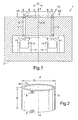
- FIG. 1 is a sketch cross sectional view through the vibration testing apparatus according to the present invention, generally designated 1.
- the vibration testing apparatus 1 comprises a rigid support 2, formed of a rigid, massive material, for example cast metal such as cast steel.
- the support 2 includes an annular face 3 facing an annular space, in which is mounted an annular body 5 which will be described further below.
- the support further comprises an inner body 4 in the form of a cylindrical section, which is supported by structures which are not shown and which is provided to support the annular body 5 on the inside.
- the annular body 5 is mounted to the support on its outer surface at the top by bearings 6 and at the bottom by bearings 7. It is mounted to the inner body 4 at its inner surface by bearings 8 at the top and bearings 9 at the bottom.
- annular body 5 is connected to an annular head expander 10.
- annular body 5 and the head expander 10 form a mounting for an annular piece of equipment to be tested (not shown). They may each be made of light magnesium alloy, for a combination of strength and lightness.
- the annular body 5 is connected at the bottom to armatures 11 of electromagnetic vibration generators 12. Any number of electromagnetic vibration generators 12 may be used. Two are shown, but three or four may be used instead.
- the electromagnetic vibration generators are each mounted on support structures 13 which are themselves rigidly mounted in the support 2.
- vibration generator 12 Any suitable design of vibration generator 12 may be used, for example as described in GB2217521.
- Each of the bearings 6, 7, 8 and 9 comprise hydrostatic bearings.
- Sources of pressurised bearing fluid (not shown) will be provided in a manner known in the art.
- the arrow R denotes the radial direction.
- Arrow A denotes the axial direction.
- the curved arrow V denotes a rocking direction of rigid vibrational modes of equipment to be tested mounted on the head expander 10. It is desired in the invention to reduce the amplitude and/or increase the frequency of vibrational modes in the direction V whilst allowing the apparatus to be relatively flexible in the radial direction R so that vibrational forces can be transmitted from the generators 12 to the equipment to be tested.
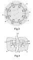
- Figure 2 is a sketch isometric view of the annular body 5 of figure 1. It can be seen that it comprises an annular body 5 of diameter D which is in the range 1-3.0 metres and a height H, in the axial direction A, of about 3.0 metres.
- the radial extent or width W of the annular body will be selected to give adequate stiffness so that there are substantially no flexing vibration modes in the frequency range of interest (5-150 Hz). In this case, the radial width W is of the order of 0.1 metres.
- One set of bearings 6, 7 is shown schematically on the outer face of the annular member 5. In practice, as will be clear in figure 3, many more sets of bearings will be provided.
- FIG 4 is a part cross sectional view of one of the bearing sets.
- Each of the bearing sets comprises hydrostatic bearings 6 and 8 of known design.
- Each is mounted to the annular body 5 by a short, rigid arm 14 or 15 respectively. These arms 14 and 15 have substantially no vibrational modes in the frequency range of interest.
- the bearings 6 and 8 are each mounted to the respective part of the support 2, 4 by a bearing arm 16, 17 respectively.
- the bearing arms 16 and 17 are designed so that they are rigid in the tangential direction T but are relatively flexible in the radial direction R.
- the bearing 6 and 8 are designed so that annular body 5 is substantially unconstrained in the axial direction A so that vibrational forces can be transmitted from the electromagnetic vibration generators 12 through the annular body 5 and the head expander 10 to equipment to be tested.
- FIG 5 is a partial sketch isometric view of the bearing shown in figure 4. Only the bearing 8 is shown. The bearing 6 is not shown, for clarity. It can be seen that the bearing comprises a pair of rigid arms 14 and a pair of rigid arms 17 as described in relation to figure 4.
- a shaft 18, which extends in the axial direction A extends between the arms 14 and is received in a bearing receiver 19 which is mounted on the other pair of arms 17.
- the shaft 18 is axially slidable within the bearing receiver 19, so that the annular body 5 is axially unconstrained by the bearing 8, within the limits imposed by the arms 14.
- the whole weight of the mounting and the equipment to be tested is then taken by the vibration generators 12.
- This design of bearing also allows the effect of thermal expansion to be accommodated.
- hydrostatic bearings 6, 8 are very small. This can give problems due to thermal expansion or due to differential loading of the annular ring 5 by equipment to be tested. However, the flexible support for the bearings 6, 8 allows such variations to be taken up without causing the bearings to jam.
Landscapes
- Physics & Mathematics (AREA)
- General Physics & Mathematics (AREA)
- Testing Of Devices, Machine Parts, Or Other Structures Thereof (AREA)
- Apparatuses For Generation Of Mechanical Vibrations (AREA)
Applications Claiming Priority (2)
| Application Number | Priority Date | Filing Date | Title |
|---|---|---|---|
| GB0411446A GB2414285A (en) | 2004-05-21 | 2004-05-21 | A vibration testing apparatus and a method of vibration testing |
| GB0411446 | 2004-05-21 |
Publications (3)
| Publication Number | Publication Date |
|---|---|
| EP1598653A2 true EP1598653A2 (de) | 2005-11-23 |
| EP1598653A3 EP1598653A3 (de) | 2006-07-05 |
| EP1598653B1 EP1598653B1 (de) | 2016-02-17 |
Family
ID=32607790
Family Applications (1)
| Application Number | Title | Priority Date | Filing Date |
|---|---|---|---|
| EP05253104.3A Expired - Lifetime EP1598653B1 (de) | 2004-05-21 | 2005-05-19 | Vorrichtung und Verfahren zur Schwingungsprüfung |
Country Status (2)
| Country | Link |
|---|---|
| EP (1) | EP1598653B1 (de) |
| GB (1) | GB2414285A (de) |
Cited By (3)
| Publication number | Priority date | Publication date | Assignee | Title |
|---|---|---|---|---|
| CN103048104A (zh) * | 2012-12-06 | 2013-04-17 | 上海裕达实业公司 | 一种用于大型空间飞行器地面振动试验夹具 |
| CN103063387A (zh) * | 2012-12-25 | 2013-04-24 | 苏州长菱测试技术有限公司 | 弹性模片的振动测试系统及方法 |
| CN108760359A (zh) * | 2018-06-22 | 2018-11-06 | 常州西南交通大学轨道交通研究院 | 一种配备垂向电磁激振器的滚轮试验台 |
Families Citing this family (3)
| Publication number | Priority date | Publication date | Assignee | Title |
|---|---|---|---|---|
| CN102539095B (zh) * | 2011-11-15 | 2014-06-25 | 上海卫星装备研究所 | 一种大接口扩展的高频防漏水的卫星振动试验夹具 |
| CN116412983B (zh) * | 2023-05-22 | 2025-07-22 | 江西合力照明电器有限公司 | 一种led灯具晃振测试装置 |
| DE102024134023A1 (de) | 2024-11-20 | 2026-05-21 | Deutsches Zentrum für Luft- und Raumfahrt e.V. | Testvorrichtung und Verfahren zum Testen von Bauteilen |
Family Cites Families (7)
| Publication number | Priority date | Publication date | Assignee | Title |
|---|---|---|---|---|
| US3062041A (en) * | 1960-05-13 | 1962-11-06 | Walter G Spodnewski | Degaussing plate assembly for electromagnetic vibration exciter |
| US3670563A (en) * | 1970-10-05 | 1972-06-20 | Nasa | Fixture for supporting articles during vibration tests |
| GB2183002B (en) * | 1985-11-19 | 1989-10-25 | Derritron Group | Electromagnetic vibrators |
| US4715229A (en) * | 1986-05-05 | 1987-12-29 | Ling Electronics, Inc. | Apparatus for vibration testing |
| GB2217521B (en) * | 1988-04-20 | 1992-09-30 | Ling Dynamic Systems | Electromagnetic vibration generators |
| JP3767273B2 (ja) * | 1999-09-24 | 2006-04-19 | 富士通株式会社 | 回転振動試験機 |
| US6443013B1 (en) * | 2000-08-04 | 2002-09-03 | Samsung Electronics Co., Ltd. | Rotary test fixture |
-
2004
- 2004-05-21 GB GB0411446A patent/GB2414285A/en not_active Withdrawn
-
2005
- 2005-05-19 EP EP05253104.3A patent/EP1598653B1/de not_active Expired - Lifetime
Non-Patent Citations (1)
| Title |
|---|
| None |
Cited By (6)
| Publication number | Priority date | Publication date | Assignee | Title |
|---|---|---|---|---|
| CN103048104A (zh) * | 2012-12-06 | 2013-04-17 | 上海裕达实业公司 | 一种用于大型空间飞行器地面振动试验夹具 |
| CN103048104B (zh) * | 2012-12-06 | 2015-06-24 | 上海裕达实业公司 | 一种用于大型空间飞行器地面振动试验夹具 |
| CN103063387A (zh) * | 2012-12-25 | 2013-04-24 | 苏州长菱测试技术有限公司 | 弹性模片的振动测试系统及方法 |
| CN103063387B (zh) * | 2012-12-25 | 2015-11-18 | 苏州长菱测试技术有限公司 | 弹性模片的振动测试系统及方法 |
| CN108760359A (zh) * | 2018-06-22 | 2018-11-06 | 常州西南交通大学轨道交通研究院 | 一种配备垂向电磁激振器的滚轮试验台 |
| CN108760359B (zh) * | 2018-06-22 | 2024-01-02 | 常州西南交通大学轨道交通研究院 | 一种配备垂向电磁激振器的滚轮试验台 |
Also Published As
| Publication number | Publication date |
|---|---|
| EP1598653A3 (de) | 2006-07-05 |
| EP1598653B1 (de) | 2016-02-17 |
| GB0411446D0 (en) | 2004-06-23 |
| GB2414285A (en) | 2005-11-23 |
Similar Documents
| Publication | Publication Date | Title |
|---|---|---|
| US7051593B2 (en) | Vibration testing apparatus and a method of vibration testing | |
| US8156832B2 (en) | Mechanical vibrator having eccentric masses | |
| US4941134A (en) | Sonic generator | |
| EP1598653B1 (de) | Vorrichtung und Verfahren zur Schwingungsprüfung | |
| US4150588A (en) | Dynamic vibration absorber | |
| US10773259B2 (en) | Eccentric assembly for gyratory or cone crusher | |
| US4033642A (en) | Shaft mounting apparatus | |
| JP6495200B2 (ja) | 宇宙環境試験装置の支持脚構造 | |
| US4977342A (en) | Electromagnetic vibration generators | |
| US6746005B1 (en) | Constant natural frequency passive-active mount | |
| JP4965816B2 (ja) | 振動試験装置及び振動試験方法 | |
| CN105006911B (zh) | 一种用于深层土壤的防水激振器 | |
| RU2239808C2 (ru) | Стенд для испытаний изделия на совместное воздействие вибрационных и линейных ускорений | |
| JP2000205332A (ja) | 防振支持装置 | |
| JP2006118968A (ja) | 振動試験用多軸加振装置 | |
| US7812494B2 (en) | Support in a stator | |
| JP4948153B2 (ja) | 遠心力載荷装置 | |
| RU2246993C1 (ru) | Трубная многокамерная мельница | |
| SU551465A1 (ru) | Виброгас ща опора | |
| US3372575A (en) | Wraparound vibration generator in a mechanical impedance measuring device | |
| SU1135621A2 (ru) | Устройство дл вибрационной обработки | |
| SU1018720A1 (ru) | Вибровозбудитель | |
| RU17458U1 (ru) | Грохот инерционный | |
| Sivak | Experimental investigation of the sensitivity of a rotating shell to the position of its axis | |
| JP2005155745A (ja) | 制振軸受ユニット |
Legal Events
| Date | Code | Title | Description |
|---|---|---|---|
| PUAI | Public reference made under article 153(3) epc to a published international application that has entered the european phase |
Free format text: ORIGINAL CODE: 0009012 |
|
| AK | Designated contracting states |
Kind code of ref document: A2 Designated state(s): AT BE BG CH CY CZ DE DK EE ES FI FR GB GR HU IE IS IT LI LT LU MC NL PL PT RO SE SI SK TR |
|
| AX | Request for extension of the european patent |
Extension state: AL BA HR LV MK YU |
|
| PUAL | Search report despatched |
Free format text: ORIGINAL CODE: 0009013 |
|
| AK | Designated contracting states |
Kind code of ref document: A3 Designated state(s): AT BE BG CH CY CZ DE DK EE ES FI FR GB GR HU IE IS IT LI LT LU MC NL PL PT RO SE SI SK TR |
|
| AX | Request for extension of the european patent |
Extension state: AL BA HR LV MK YU |
|
| 17P | Request for examination filed |
Effective date: 20061229 |
|
| AKX | Designation fees paid |
Designated state(s): DE FR GB |
|
| RAP1 | Party data changed (applicant data changed or rights of an application transferred) |
Owner name: LDS TEST AND MEASUREMENT INC. |
|
| RAP1 | Party data changed (applicant data changed or rights of an application transferred) |
Owner name: BRUEL & KJAER NORTH AMERICA, INC. |
|
| RAP1 | Party data changed (applicant data changed or rights of an application transferred) |
Owner name: LDS TEST AND MEASUREMENT LIMITED |
|
| 17Q | First examination report despatched |
Effective date: 20110211 |
|
| RAP1 | Party data changed (applicant data changed or rights of an application transferred) |
Owner name: BRUEL & KJAER VTS LIMITED |
|
| RIC1 | Information provided on ipc code assigned before grant |
Ipc: G01M 7/04 20060101AFI20120427BHEP |
|
| GRAP | Despatch of communication of intention to grant a patent |
Free format text: ORIGINAL CODE: EPIDOSNIGR1 |
|
| INTG | Intention to grant announced |
Effective date: 20150730 |
|
| GRAS | Grant fee paid |
Free format text: ORIGINAL CODE: EPIDOSNIGR3 |
|
| GRAA | (expected) grant |
Free format text: ORIGINAL CODE: 0009210 |
|
| AK | Designated contracting states |
Kind code of ref document: B1 Designated state(s): DE FR GB |
|
| REG | Reference to a national code |
Ref country code: GB Ref legal event code: FG4D |
|
| REG | Reference to a national code |
Ref country code: DE Ref legal event code: R096 Ref document number: 602005048450 Country of ref document: DE |
|
| REG | Reference to a national code |
Ref country code: FR Ref legal event code: PLFP Year of fee payment: 12 |
|
| REG | Reference to a national code |
Ref country code: DE Ref legal event code: R097 Ref document number: 602005048450 Country of ref document: DE |
|
| PLBE | No opposition filed within time limit |
Free format text: ORIGINAL CODE: 0009261 |
|
| STAA | Information on the status of an ep patent application or granted ep patent |
Free format text: STATUS: NO OPPOSITION FILED WITHIN TIME LIMIT |
|
| 26N | No opposition filed |
Effective date: 20161118 |
|
| REG | Reference to a national code |
Ref country code: FR Ref legal event code: PLFP Year of fee payment: 13 |
|
| REG | Reference to a national code |
Ref country code: FR Ref legal event code: PLFP Year of fee payment: 14 |
|
| P01 | Opt-out of the competence of the unified patent court (upc) registered |
Effective date: 20230530 |
|
| PGFP | Annual fee paid to national office [announced via postgrant information from national office to epo] |
Ref country code: GB Payment date: 20240419 Year of fee payment: 20 |
|
| PGFP | Annual fee paid to national office [announced via postgrant information from national office to epo] |
Ref country code: DE Payment date: 20240418 Year of fee payment: 20 |
|
| PGFP | Annual fee paid to national office [announced via postgrant information from national office to epo] |
Ref country code: FR Payment date: 20240418 Year of fee payment: 20 |
|
| REG | Reference to a national code |
Ref country code: DE Ref legal event code: R071 Ref document number: 602005048450 Country of ref document: DE |
|
| REG | Reference to a national code |
Ref country code: GB Ref legal event code: PE20 Expiry date: 20250518 |
|
| PG25 | Lapsed in a contracting state [announced via postgrant information from national office to epo] |
Ref country code: GB Free format text: LAPSE BECAUSE OF EXPIRATION OF PROTECTION Effective date: 20250518 |