US4977342A - Electromagnetic vibration generators - Google Patents
Electromagnetic vibration generators Download PDFInfo
- Publication number
- US4977342A US4977342A US07/339,028 US33902889A US4977342A US 4977342 A US4977342 A US 4977342A US 33902889 A US33902889 A US 33902889A US 4977342 A US4977342 A US 4977342A
- Authority
- US
- United States
- Prior art keywords
- armature
- pair
- suspension
- vibration generator
- electromagnetic vibration
- Prior art date
- Legal status (The legal status is an assumption and is not a legal conclusion. Google has not performed a legal analysis and makes no representation as to the accuracy of the status listed.)
- Expired - Lifetime
Links
Images

Classifications
-
- H—ELECTRICITY
- H02—GENERATION; CONVERSION OR DISTRIBUTION OF ELECTRIC POWER
- H02K—DYNAMO-ELECTRIC MACHINES
- H02K33/00—Motors with reciprocating, oscillating or vibrating magnet, armature or coil system
- H02K33/18—Motors with reciprocating, oscillating or vibrating magnet, armature or coil system with coil systems moving upon intermittent or reversed energisation thereof by interaction with a fixed field system, e.g. permanent magnets
-
- G—PHYSICS
- G01—MEASURING; TESTING
- G01M—TESTING STATIC OR DYNAMIC BALANCE OF MACHINES OR STRUCTURES; TESTING OF STRUCTURES OR APPARATUS, NOT OTHERWISE PROVIDED FOR
- G01M7/00—Vibration-testing of structures; Shock-testing of structures
- G01M7/02—Vibration-testing by means of a shake table
- G01M7/04—Monodirectional test stands
Definitions
- the present invention relates to electromagnetic vibration generators, sometimes known in the art as shakers, which are employed for the vibration testing of components, apparatus and equipment in numerous branches of industry and research.
- Such electromagnetic vibration generators basically consist of an armature which is suspended from a rigid body or stator and having a coil carried by the armature located in an air gap in the stator.
- a D.C. magnetic field is generated across the air gap either by permanent magnets or electromagnets and when an alternating current is fed through the armature coil, the armature is caused to vibrate along its axis at the frequency of the applied alternating current.
- the armature is mounted on bearings and has peripheral suspension members which center the armature in the air gap and allow free movement along its axis of vibration but which impose a high stiffness to any lateral movement of the armature normal to its axis of vibration.
- An article to be vibration tested may be placed directly on top of the armature or on a work table carried by the armature when the vibration testing is to be carried out in the vertical mode, or the article to be tested may be placed on a horizontal slip table coupled to the armature when the vibration testing is to be carried out in the horizontal mode, as is well known in the art.
- armature suspension systems are designed to provide a high degree of stiffness to any lateral movement of the armature
- existing systems do not necessarily provide a high restraint to torsional forces tending to cause turning movement of the armature about its axis of vibration.
- Such torsional forces may be induced partly due to the helical form of the armature coil and/or by resonances induced in the armature in relation to its suspension system at one or more particular frequencies throughout the range of frequencies employed for the vibration testing. This can in turn give rise to problems during the vibration testing of certain types of components, such as gyroscopes, which are sensitive to spurious rotational forces or movements.
- the armature suspension members which allow free movement of the armature along its axis of vibration but which exhibit a stiffness to lateral movement of the armature, are arranged in pairs with the two members of a pair at an angle to each other about the periphery of the armature and the stiffness of one suspension member of each pair is employed to restrain turning forces acting on the armature in one direction of rotation whilst the stiffness of the other suspension member of each pair is employed to restrain turning forces acting on the armature in the opposite direction of rotation.
- the invention also provides an electromagnetic vibration generator in which the armature for transmitting the vibrations generated to an article to be tested is suspended at its periphery by a plurality of suspension members which are arranged in pairs and allow free movement of the armature along its axis of vibration, the two members of each pair being arranged at an angle to each other and so disposed that any torsional force generated in the armature which attempts to cause turning of the armature about its axis of vibration exerts a compressive force on one suspension member of each pair for one direction of said torsional force and a compressive force on the other suspension member of each pair for the opposite direction of said torsional force, said compressive force being exerted on said suspension members in a stiffness direction of said members.
- the armature is generally of circular or cylindrical form and the number of pairs of suspension members arranged about the periphery of the armature must be at least three and is preferably four or five. However a higher number of pairs of suspension members may be necessary on large vibration generators.
- the angle between the two suspension members of a pair is not critical provided that the desired effect is obtained of the suspension members restraining turning forces on the armature. This angle will depend to some extent on the number of pairs of suspension members and the nature of the suspension members employed.
- the angle between the two suspension members of a pair is approximately a right angle. Whatever the angle, the two suspension members of a pair are arranged so that the angle between them is bisected by a radius extending from the axis of vibration of the armature.
- the suspension member may be of any design which allows free movement of the armature along its axis of vibration but which presents a high stiffness to compressive forces applied to the suspension member as a result of torsion of the armature.
- the suspension members may comprise pivoted struts, flexures, which may be laminated, rotatable bushes or bearings; or a combination of any of such devices.
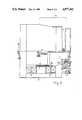
- FIG. 1 is a view from the armature end of one embodiment of electromagnetic vibration generator according to the invention.
- FIG. 2 is a part sectional view along the line II--II in FIG. 1.
- the electromagnetic vibration generator illustrated comprises an armature 1 mounted for vibratory movement relative to a rigid stator or body 2.
- the latter is provided with trunnions 2a by which it is supported in a rigid frame (not shown) so that the vibration generator can be oriented either for vibration along a vertical axis or along a horizontal axis.
- the body is provided with an annular air gap 3 across which is produced a D.C. magnetic field generated by the coils 4 and within which is located a coil 5 attached to the lower end 1a of the armature structure.
- armature 1 Energisation of the armature coil 5 by an alternating current causes the armature 1 to vibrate, relative to the body 2, along its longitudinal axis at the frequency of the alternating current applied to the coil 5.
- the armature 1 is mounted on an axially located bearing 6, for example a hydrostatic bearing, which allows free movement of the armature along its vibratory axis but which restrains lateral movement of the armature.
- the periphery of the armature 1 is supported from the body 2 by suspension members, generally indicated at 7, which serve to center the armature coil 5 in the air gap 3 and which also allow free movement of the armature along its axis of vibration but have a high stiffness to any lateral movement of the armature.
- the present invention provides a suspension arrangement which also affords a high restraint to any torsional forces acting on the armature 1 and tending to turn it about its axis of rotation.
- Such forces may, for example, be generated by resonances induced in the armature at certain frequencies of vibration or by the helical form of the armature coil 5.
- the suspension members 7 are arranged in pairs 7a, 7b at an angle to each other and at such an attitude to the armature that any torsional force generated which attempts to rotate the armature in one direction is highly restrained by that force attempting to compress a component of the suspension members 7a in a direction where that component exhibits a high stiffness whilst, similarly, any torsional force generated which attempts to rotate the armature in the opposite direction likewise is restrained by the high stiffness of the corresponding component of the suspension members 7b.
- the two suspension members 7a, 7b of a pair are disposed at right angles to each other and this angle is bisected by a radius from the axis of rotation of the armature.
- the construction and arrangement of the suspension members employed in this embodiment will now be described in greater detail.
- four pairs of suspension members are equally spaced around the periphery of the armature 1 and are located adjacent the upper face 1b of the armature, which forms a working platform to which an article to be vibration tested may be secured, e.g. by bolts.
- the armature structure is formed as a metal casting and is provided with four projections 8, each having two adjacent faces 8a at right angles, equally spaced around its periphery.
- the body 2 is likewise provided with projections 9 having faces 9a disposed such that a face 9a on the body 2 is opposite each face 8a on the armature 1.
- Each suspension member is of the so-called rolling strut type and comprises a rubber to metal bushing 10 having its outer shell 10a secured to a face 8a and its inner axial bearing 10b connected to one end of a strut 11.
- the other end of the strut is formed as an arcuate surface 11a which has one edge secured at 12 to one end of a flexure member 13 which is attached at its other end to the associated face 9a on the stator 2.
- axial movement of the armature 1 will cause the arcuate surface 11a of the strut 11 to roll over the adjacent surface of the flexure member 13 whilst the other end of the strut 11 pivots due to the flexing of the rubber bush bonded between the axial bearing 10b and outer shell 10a.
- suspension structures are stiff so far as lateral movement of the armature is concerned and also offer a high restraint to any torsional forces acting on the armature since such forces act in compression on the high stiffness direction of components of the suspension structures.
- One suspension member of each pair acts to restrain torsional forces acting in one direction, whilst the other suspension member of each pair acts to restrain torsional forces acting in the opposite direction.
- each suspension member may comprise a roller member having two oppositely directed arcuate faces which are respectively secured to one end of two flexure members having their opposite ends respectively secured to the associated opposed faces 8a and 9a.
Landscapes
- Engineering & Computer Science (AREA)
- Power Engineering (AREA)
- Physics & Mathematics (AREA)
- General Physics & Mathematics (AREA)
- Apparatuses For Generation Of Mechanical Vibrations (AREA)
Abstract
Description
Claims (9)
Applications Claiming Priority (2)
| Application Number | Priority Date | Filing Date | Title |
|---|---|---|---|
| GB8809289A GB2217521B (en) | 1988-04-20 | 1988-04-20 | Electromagnetic vibration generators |
| GB8809289 | 1988-04-20 |
Publications (1)
| Publication Number | Publication Date |
|---|---|
| US4977342A true US4977342A (en) | 1990-12-11 |
Family
ID=10635492
Family Applications (1)
| Application Number | Title | Priority Date | Filing Date |
|---|---|---|---|
| US07/339,028 Expired - Lifetime US4977342A (en) | 1988-04-20 | 1989-04-17 | Electromagnetic vibration generators |
Country Status (2)
| Country | Link |
|---|---|
| US (1) | US4977342A (en) |
| GB (1) | GB2217521B (en) |
Cited By (8)
| Publication number | Priority date | Publication date | Assignee | Title |
|---|---|---|---|---|
| US6035715A (en) * | 1997-09-15 | 2000-03-14 | Entela, Inc, | Method and apparatus for optimizing the design of a product |
| US6131461A (en) * | 1998-09-01 | 2000-10-17 | Mb Dynamics | Flexure assembly |
| US6247366B1 (en) | 1997-09-15 | 2001-06-19 | Alexander J. Porter | Design maturity algorithm |
| US6389900B1 (en) | 1998-09-01 | 2002-05-21 | Mb Dynamics | Flexure assembly |
| US20030163269A1 (en) * | 1997-09-15 | 2003-08-28 | Porter Alexander J. | Control system for a failure mode testing system |
| US6914351B2 (en) | 2003-07-02 | 2005-07-05 | Tiax Llc | Linear electrical machine for electric power generation or motive drive |
| US20070108850A1 (en) * | 2005-11-17 | 2007-05-17 | Tiax Llc | Linear electrical machine for electric power generation or motive drive |
| US9190881B1 (en) | 2011-08-02 | 2015-11-17 | Tooltek Engineering Corporation | Rotary-powered mechanical oscillator |
Families Citing this family (4)
| Publication number | Priority date | Publication date | Assignee | Title |
|---|---|---|---|---|
| US5493511A (en) * | 1992-12-08 | 1996-02-20 | Administrator, National Aeronautics And Space Administration | High speed thin plate fatigue crack monitor |
| JP4965816B2 (en) * | 2004-05-21 | 2012-07-04 | ブリュエル アンド ケアー ブイティーエス リミテッド | Vibration test apparatus and vibration test method |
| US7051593B2 (en) | 2004-05-21 | 2006-05-30 | Ling Dynamic Systems, Inc. | Vibration testing apparatus and a method of vibration testing |
| GB2414285A (en) * | 2004-05-21 | 2005-11-23 | Ling Dynamic Systems Inc | A vibration testing apparatus and a method of vibration testing |
Citations (1)
| Publication number | Priority date | Publication date | Assignee | Title |
|---|---|---|---|---|
| GB1449014A (en) * | 1973-10-04 | 1976-09-08 | Ling Dynamic Systems | Vibrators |
-
1988
- 1988-04-20 GB GB8809289A patent/GB2217521B/en not_active Expired - Lifetime
-
1989
- 1989-04-17 US US07/339,028 patent/US4977342A/en not_active Expired - Lifetime
Patent Citations (1)
| Publication number | Priority date | Publication date | Assignee | Title |
|---|---|---|---|---|
| GB1449014A (en) * | 1973-10-04 | 1976-09-08 | Ling Dynamic Systems | Vibrators |
Cited By (15)
| Publication number | Priority date | Publication date | Assignee | Title |
|---|---|---|---|---|
| US20060161398A1 (en) * | 1997-09-15 | 2006-07-20 | Porter Alexander J | Control system for a failure mode testing system |
| US7136769B2 (en) | 1997-09-15 | 2006-11-14 | Entela, Inc. | Control system for a failure mode testing system |
| US6247366B1 (en) | 1997-09-15 | 2001-06-19 | Alexander J. Porter | Design maturity algorithm |
| US7260492B2 (en) | 1997-09-15 | 2007-08-21 | Intertek Etl Entela | Control system for a failure mode testing system |
| US20070061095A1 (en) * | 1997-09-15 | 2007-03-15 | Porter Alexander J | Control system for a failure mode testing system |
| US20030163269A1 (en) * | 1997-09-15 | 2003-08-28 | Porter Alexander J. | Control system for a failure mode testing system |
| US6035715A (en) * | 1997-09-15 | 2000-03-14 | Entela, Inc, | Method and apparatus for optimizing the design of a product |
| US7024323B2 (en) | 1997-09-15 | 2006-04-04 | Entela, Inc. | Control system for a failure mode testing system |
| US20050049807A1 (en) * | 1997-09-15 | 2005-03-03 | Porter Alexander J. | Control system for a failure mode testing system |
| US6131461A (en) * | 1998-09-01 | 2000-10-17 | Mb Dynamics | Flexure assembly |
| US6571637B2 (en) | 1998-09-01 | 2003-06-03 | Mb Dynamics | Flexure assembly |
| US6389900B1 (en) | 1998-09-01 | 2002-05-21 | Mb Dynamics | Flexure assembly |
| US6914351B2 (en) | 2003-07-02 | 2005-07-05 | Tiax Llc | Linear electrical machine for electric power generation or motive drive |
| US20070108850A1 (en) * | 2005-11-17 | 2007-05-17 | Tiax Llc | Linear electrical machine for electric power generation or motive drive |
| US9190881B1 (en) | 2011-08-02 | 2015-11-17 | Tooltek Engineering Corporation | Rotary-powered mechanical oscillator |
Also Published As
| Publication number | Publication date |
|---|---|
| GB2217521A (en) | 1989-10-25 |
| GB2217521B (en) | 1992-09-30 |
| GB8809289D0 (en) | 1988-05-25 |
Similar Documents
| Publication | Publication Date | Title |
|---|---|---|
| US4977342A (en) | Electromagnetic vibration generators | |
| EP0790180B1 (en) | Rotor system vibration absorber | |
| US4619349A (en) | Vibration isolator | |
| US4596158A (en) | Tuned gyroscope with dynamic absorber | |
| CA1306040C (en) | Electromagnetic device for reducing vibration in a rotary machine fitted with fluid bearings | |
| JPS6025319B2 (en) | vibration absorber | |
| US5022628A (en) | Mounting for machinery | |
| EP2292335B1 (en) | Centrifuge with shaft-coupling capable of maintaining motor shaft concentricity | |
| US5351545A (en) | Electromagnetic vibration generators | |
| US3258111A (en) | Adjustable feed angle parts feeder | |
| US4150588A (en) | Dynamic vibration absorber | |
| EP0547469A1 (en) | Active, elastic support | |
| US3322377A (en) | Anti-vibration resilient supports | |
| WO2018075297A1 (en) | Horizontal-motion vibration isolator | |
| US4720060A (en) | Anti-resonant suspension device having six degrees of freedom for a helicopter | |
| EP1448461A1 (en) | Exciter mass assembly for a vibratory device | |
| US4687463A (en) | Centrifugal decanter of the pendulous type | |
| US4315817A (en) | Vibrating surface apparatus | |
| GB2316732A (en) | Vibration reduction | |
| DE69203518T2 (en) | Hybrid vibration damper with active magnetic vibration generator. | |
| US3395296A (en) | Dynamoelectric machine mounting with reduced stator vibration | |
| JPH07303346A (en) | Electric motor and device provided with the motor | |
| SU1060764A1 (en) | Vibration-insulated foundation | |
| CA1091178A (en) | Vibrating surface apparatus | |
| EP1241371B1 (en) | Vibration isolation system |
Legal Events
| Date | Code | Title | Description |
|---|---|---|---|
| STCF | Information on status: patent grant |
Free format text: PATENTED CASE |
|
| FEPP | Fee payment procedure |
Free format text: PAT HOLDER CLAIMS SMALL ENTITY STATUS - SMALL BUSINESS (ORIGINAL EVENT CODE: SM02); ENTITY STATUS OF PATENT OWNER: LARGE ENTITY |
|
| FPAY | Fee payment |
Year of fee payment: 4 |
|
| FPAY | Fee payment |
Year of fee payment: 8 |
|
| FEPP | Fee payment procedure |
Free format text: PAT HOLDER NO LONGER CLAIMS SMALL ENTITY STATUS, ENTITY STATUS SET TO UNDISCOUNTED (ORIGINAL EVENT CODE: STOL); ENTITY STATUS OF PATENT OWNER: LARGE ENTITY |
|
| REFU | Refund |
Free format text: REFUND - PAYMENT OF MAINTENANCE FEE, 12TH YR, SMALL ENTITY (ORIGINAL EVENT CODE: R285); ENTITY STATUS OF PATENT OWNER: LARGE ENTITY |
|
| FPAY | Fee payment |
Year of fee payment: 12 |
|
| AS | Assignment |
Owner name: LING DYNAMIC SYSTEMS LIMITED, UNITED KINGDOM Free format text: ASSIGNMENT OF ASSIGNORS INTEREST;ASSIGNOR:ADAMS, ANTHONY BRIAN;REEL/FRAME:021669/0855 Effective date: 19890407 |
|
| AS | Assignment |
Owner name: LDS TEST AND MEASUREMENT LIMITED, UNITED KINGDOM Free format text: CHANGE OF NAME;ASSIGNOR:LING DYNAMIC SYSTEMS LIMITED;REEL/FRAME:021719/0652 Effective date: 20040401 |