EP1598620A2 - Vibration reduction type refrigerator - Google Patents

Vibration reduction type refrigerator Download PDF

Info

Publication number
EP1598620A2
EP1598620A2 EP04030807A EP04030807A EP1598620A2 EP 1598620 A2 EP1598620 A2 EP 1598620A2 EP 04030807 A EP04030807 A EP 04030807A EP 04030807 A EP04030807 A EP 04030807A EP 1598620 A2 EP1598620 A2 EP 1598620A2
Authority
EP
European Patent Office
Prior art keywords
pipe
refrigerator
unit
mechanical chamber
compressor
Prior art date
Legal status (The legal status is an assumption and is not a legal conclusion. Google has not performed a legal analysis and makes no representation as to the accuracy of the status listed.)
Granted
Application number
EP04030807A
Other languages
German (de)
French (fr)
Other versions
EP1598620A3 (en
EP1598620B1 (en
Inventor
Dong-Hoon Lee
Tae-Hee Lee
Yong-Gu Kim
Young-Hoon Yun
Current Assignee (The listed assignees may be inaccurate. Google has not performed a legal analysis and makes no representation or warranty as to the accuracy of the list.)
LG Electronics Inc
Original Assignee
LG Electronics Inc
Priority date (The priority date is an assumption and is not a legal conclusion. Google has not performed a legal analysis and makes no representation as to the accuracy of the date listed.)
Filing date
Publication date
Application filed by LG Electronics Inc filed Critical LG Electronics Inc
Publication of EP1598620A2 publication Critical patent/EP1598620A2/en
Publication of EP1598620A3 publication Critical patent/EP1598620A3/en
Application granted granted Critical
Publication of EP1598620B1 publication Critical patent/EP1598620B1/en
Anticipated expiration legal-status Critical
Expired - Lifetime legal-status Critical Current

Links

Images

Classifications

    • EFIXED CONSTRUCTIONS
    • E03WATER SUPPLY; SEWERAGE
    • E03DWATER-CLOSETS OR URINALS WITH FLUSHING DEVICES; FLUSHING VALVES THEREFOR
    • E03D9/00Sanitary or other accessories for lavatories ; Devices for cleaning or disinfecting the toilet room or the toilet bowl; Devices for eliminating smells
    • E03D9/02Devices adding a disinfecting, deodorising, or cleaning agent to the water while flushing
    • E03D9/03Devices adding a disinfecting, deodorising, or cleaning agent to the water while flushing consisting of a separate container with an outlet through which the agent is introduced into the flushing water, e.g. by suction ; Devices for agents in direct contact with flushing water
    • E03D9/031Devices connected to or dispensing into the flushing pipe
    • FMECHANICAL ENGINEERING; LIGHTING; HEATING; WEAPONS; BLASTING
    • F25REFRIGERATION OR COOLING; COMBINED HEATING AND REFRIGERATION SYSTEMS; HEAT PUMP SYSTEMS; MANUFACTURE OR STORAGE OF ICE; LIQUEFACTION SOLIDIFICATION OF GASES
    • F25DREFRIGERATORS; COLD ROOMS; ICE-BOXES; COOLING OR FREEZING APPARATUS NOT OTHERWISE PROVIDED FOR
    • F25D21/00Defrosting; Preventing frosting; Removing condensed or defrost water
    • F25D21/14Collecting or removing condensed and defrost water; Drip trays
    • FMECHANICAL ENGINEERING; LIGHTING; HEATING; WEAPONS; BLASTING
    • F25REFRIGERATION OR COOLING; COMBINED HEATING AND REFRIGERATION SYSTEMS; HEAT PUMP SYSTEMS; MANUFACTURE OR STORAGE OF ICE; LIQUEFACTION SOLIDIFICATION OF GASES
    • F25DREFRIGERATORS; COLD ROOMS; ICE-BOXES; COOLING OR FREEZING APPARATUS NOT OTHERWISE PROVIDED FOR
    • F25D23/00General constructional features
    • F25D23/006General constructional features for mounting refrigerating machinery components
    • FMECHANICAL ENGINEERING; LIGHTING; HEATING; WEAPONS; BLASTING
    • F25REFRIGERATION OR COOLING; COMBINED HEATING AND REFRIGERATION SYSTEMS; HEAT PUMP SYSTEMS; MANUFACTURE OR STORAGE OF ICE; LIQUEFACTION SOLIDIFICATION OF GASES
    • F25BREFRIGERATION MACHINES, PLANTS OR SYSTEMS; COMBINED HEATING AND REFRIGERATION SYSTEMS; HEAT PUMP SYSTEMS
    • F25B2500/00Problems to be solved
    • F25B2500/13Vibrations
    • FMECHANICAL ENGINEERING; LIGHTING; HEATING; WEAPONS; BLASTING
    • F25REFRIGERATION OR COOLING; COMBINED HEATING AND REFRIGERATION SYSTEMS; HEAT PUMP SYSTEMS; MANUFACTURE OR STORAGE OF ICE; LIQUEFACTION SOLIDIFICATION OF GASES
    • F25DREFRIGERATORS; COLD ROOMS; ICE-BOXES; COOLING OR FREEZING APPARATUS NOT OTHERWISE PROVIDED FOR
    • F25D2321/00Details or arrangements for defrosting; Preventing frosting; Removing condensed or defrost water, not provided for in other groups of this subclass
    • F25D2321/14Collecting condense or defrost water; Removing condense or defrost water
    • F25D2321/141Removal by evaporation
    • F25D2321/1411Removal by evaporation using compressor heat
    • FMECHANICAL ENGINEERING; LIGHTING; HEATING; WEAPONS; BLASTING
    • F25REFRIGERATION OR COOLING; COMBINED HEATING AND REFRIGERATION SYSTEMS; HEAT PUMP SYSTEMS; MANUFACTURE OR STORAGE OF ICE; LIQUEFACTION SOLIDIFICATION OF GASES
    • F25DREFRIGERATORS; COLD ROOMS; ICE-BOXES; COOLING OR FREEZING APPARATUS NOT OTHERWISE PROVIDED FOR
    • F25D2500/00Problems to be solved
    • F25D2500/02Geometry problems

Definitions

  • the conventional refrigerator includes a refrigerator main body 102 having a freezing chamber for storing various frozen foods and a cooling chamber for storing various cooled foods, and a mechanical chamber 106 disposed at the rear bottom portion of the refrigerator main body 102, for housing various components of a refrigeration cycle, such as a compressor 104 for compressing refrigerants.
  • Doors 108 for opening or closing the freezing chamber and the cooling chamber are mounted at the front portion of the refrigerator main body 102, and feet 110 for supporting the refrigerator main body 102 to control the height are mounted at the lower portion of the refrigerator main body 102.
  • the vibration reduction type refrigerator further includes a discharge pipe connected between the side of the compressor and an inlet pipe of a condenser, for discharging the refrigerants compressed by the compressor to the condenser.
  • the discharge pipe includes: a first pipe unit connected to the side of the compressor; a second pipe unit connected to the first pipe unit, for passing through the space formed between the water tray and the wall surface of the mechanical chamber; and a third pipe unit connected to the second pipe unit and the inlet pipe.
  • the suction pipe 36 includes a first pipe unit 36a connected to the compressor 24, a second pipe unit 36b connected to the first pipe unit 36a, for passing through the space 64 formed between the water tray 20 and the wall surface of the mechanical chamber 16, and a third pipe unit 36c connected to the second pipe unit 36b and also connected to the outlet pipe 28 exposed on the top surface of the mechanical chamber 16.
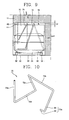
  • Fig. 8 is a cross-sectional view illustrating a mechanical chamber of a refrigerator in accordance with a second embodiment of the present invention
  • Fig. 9 is a cross-sectional view taken along line IX-IX of Fig. 8.
  • the suction pipe 72 includes a first pipe unit 72a connected to one side of the compressor 24, a second pipe unit 72b connected to the first pipe unit 72a, for passing through the space 76 formed between the top surface of the water tray 70 and the ceiling surface of the mechanical chamber 16, a third pipe unit 72c curved in the down direction from the second pipe unit 72b and inclined to the rear portion of the mechanical chamber 16, a fourth pipe unit 72d curved in the horizontal direction from the third pipe unit 72c and disposed in the forward/backward direction of the mechanical chamber 16, and a fifth pipe unit 72e curved in the up direction from the fourth pipe unit 72d and connected to the outlet pipe 28.

Landscapes

  • Engineering & Computer Science (AREA)
  • General Engineering & Computer Science (AREA)
  • Physics & Mathematics (AREA)
  • Mechanical Engineering (AREA)
  • Thermal Sciences (AREA)
  • Chemical & Material Sciences (AREA)
  • Combustion & Propulsion (AREA)
  • Public Health (AREA)
  • Health & Medical Sciences (AREA)
  • Epidemiology (AREA)
  • Life Sciences & Earth Sciences (AREA)
  • Hydrology & Water Resources (AREA)
  • Water Supply & Treatment (AREA)
  • Removal Of Water From Condensation And Defrosting (AREA)
  • Devices That Are Associated With Refrigeration Equipment (AREA)

Abstract

Disclosed is a vibration reduction type refrigerator including a refrigerator main body having a cooling chamber for storing foods and a mechanical chamber, a compressor disposed in the mechanical chamber, for compressing refrigerants, and a suction pipe connected to the side of the compressor, disposed in the mechanical chamber in the width direction of the refrigerator main body, and connected to an outlet pipe of an evaporator disposed at one side end of the mechanical chamber. The vibration reduction type refrigerator can prevent the vibration generated by the compressor from being transmitted to the refrigerator main body through the suction pipe and the discharge pipe connected to the compressor, by minimizing spaces occupied by the suction pipe and the discharge pipe in the mechanical chamber and increasing the length of the suction pipe and the discharge pipe.

Description

BACKGROUND OF THE INVENTION 1. Field of the Invention
The present invention relates to a vibration reduction type refrigerator, and more particularly to, a vibration reduction type refrigerator which can prevent vibration generated by a compressor from being transmitted to a refrigerator main body through pipes.
2. Description of the Background Art
In general, a refrigerator includes a refrigerator main body having a cooling chamber for storing various foods, and a refrigeration cycle for refrigerating the cooling chamber.
The application range of the refrigerator has been gradually expanded, such as a cosmetics refrigerator and a wine refrigerator for storing cosmetics and wines, respectively. As a variety of refrigerators are developed, researches have been made to reduce vibration of the refrigerators.
Especially, in the wine refrigerator, temperature, sunlight, humidity, vibration and horizontality must be taken into consideration to handle and store wines. It is quite easy to control sunlight, humidity and horizontality but difficult to maintain an optimum temperature and reduce vibration. Thus, researches have still been made on it.
Fig. 1 is a perspective view illustrating a mechanical chamber of a conventional refrigerator, and Fig. 2 is a cross-sectional view illustrating the mechanical chamber of the conventional refrigerator.
The conventional refrigerator includes a refrigerator main body 102 having a freezing chamber for storing various frozen foods and a cooling chamber for storing various cooled foods, and a mechanical chamber 106 disposed at the rear bottom portion of the refrigerator main body 102, for housing various components of a refrigeration cycle, such as a compressor 104 for compressing refrigerants.
Doors 108 for opening or closing the freezing chamber and the cooling chamber are mounted at the front portion of the refrigerator main body 102, and feet 110 for supporting the refrigerator main body 102 to control the height are mounted at the lower portion of the refrigerator main body 102.
A cover 112 for opening or closing the mechanical chamber 106 is fastened to the front portion of the mechanical chamber 106 by screws 114, a control box 116 for controlling the refrigeration cycle is installed at one side of the inside portion of the mechanical chamber 106, a water tray 118 for storing water generated from the refrigeration cycle by defrosting is installed at the upper portion of the inside portion of the mechanical chamber 106, a base plate 120 is mounted on the bottom surface of the mechanical chamber 106, and the compressor 104 is mounted on the base plate 120.
The compressor 104 is mounted on the base plate 120 by mounting brackets 122, and rubber vibration isolators 124 for preventing vibration generated by the compressor 104 from being transmitted to the refrigerator main body 102 are installed at the mounting brackets 122. The compressor 104 is connected to an evaporator (not shown) installed at the rear portion of the refrigerator main body 102 through a suction pipe 130, for sucking refrigerants from the evaporator, and also connected to a condenser (not shown) installed at the rear portion of the refrigerator main body 102 through a discharge pipe 132, for discharging the compressed refrigerants to the condenser.
The suction pipe 130 and the discharge pipe 132 are looped once and connected respectively to the evaporator and the condenser so as to prevent the vibration generated by the compressor 104 from being transmitted to the refrigerator main body 102 through the pipes 130 and 132. That is, the suction pipe 130 and the discharge pipe 132 are wound once in a loop shape.
In the conventional refrigerator, in order to increase the capacity of the cooling chamber as large as possible, the width of the mechanical chamber is set to be almost identical to the size of the compressor. In addition, the condensed water tray is installed at the upper portion of the mechanical chamber. It is thus restrictive to increase the length of the suction pipe and the discharge pipe. Even though the suction pipe and the discharge pipe are looped once to increase the length, the length of the suction pipe and the discharge pipe is so short that the vibration generated by the compressor may be transmitted to the refrigerator main body through the suction pipe and the discharge pipe. As a result, shelves of the refrigerator are shaken.
Especially, in the wine refrigerator, noise is a very important factor. The vibration transmitted to the cooling chamber badly ripens the wines.
SUMMARY OF THE INVENTION
Therefore, an object of the present invention is to provide a vibration reduction type refrigerator which can prevent vibration generated by a compressor from being transmitted to a refrigerator main body through a suction pipe and a discharge pipe connected to the compressor, by minimizing spaces occupied by the suction pipe and the discharge pipe in a mechanical chamber and increasing the length of the suction pipe and the discharge pipe.
To achieve these and other advantages and in accordance with the purpose of the present invention, as embodied and broadly described herein, there is provided a vibration reduction type refrigerator, including: a refrigerator main body having a cooling chamber for storing foods and a mechanical chamber; a compressor disposed in the mechanical chamber, for compressing refrigerants; and a suction pipe connected to the side of the compressor, disposed in the mechanical chamber in the width direction of the refrigerator main body, and connected to an outlet pipe of an evaporator disposed at one side end of the mechanical chamber.
Preferably, a water tray for storing water generated in the operation of a refrigeration cycle is mounted on the top surface of the mechanical chamber, and disposed at a predetermined interval from the rear wall surface of the mechanical chamber, so that a space can be formed between the side of the water tray and the rear wall surface of the mechanical chamber.
Preferably, the suction pipe includes: a first pipe unit connected to the side of the compressor; a second pipe unit connected to the first pipe unit, for passing through the space formed between the water tray and the wall surface of the mechanical chamber; and a third pipe unit connected to the second pipe unit and the outlet pipe.
Preferably, the vibration reduction type refrigerator further includes a discharge pipe connected between the side of the compressor and an inlet pipe of a condenser, for discharging the refrigerants compressed by the compressor to the condenser. Here, the discharge pipe includes: a first pipe unit connected to the side of the compressor; a second pipe unit connected to the first pipe unit, for passing through the space formed between the water tray and the wall surface of the mechanical chamber; and a third pipe unit connected to the second pipe unit and the inlet pipe.
The foregoing and other objects, features, aspects and advantages of the present invention will become more apparent from the following detailed description of the present invention when taken in conjunction with the accompanying drawings.
BRIEF DESCRIPTION OF THE DRAWINGS
The accompanying drawings, which are included to provide a further understanding of the invention and are incorporated in and constitute a part of this specification, illustrate embodiments of the invention and together with the description serve to explain the principles of the invention.
In the drawings:
  • Fig. 1 is a perspective view illustrating a mechanical chamber of a conventional refrigerator;
  • Fig. 2 is a cross-sectional view illustrating the mechanical chamber of the conventional refrigerator;
  • Fig. 3 is a cross-sectional view illustrating a mechanical chamber of a refrigerator in accordance with a first embodiment of the present invention;
  • Fig. 4 is a cross-sectional view taken along line IV-IV of Fig. 3;
  • Fig. 5 is a cross-sectional view illustrating a water tray of the refrigerator in accordance with the first embodiment of the present invention;
  • Fig. 6 is a perspective view illustrating a suction pipe of the refrigerator in accordance with the first embodiment of the present invention;
  • Fig. 7 is a perspective view illustrating a discharge pipe of the refrigerator in accordance with the first embodiment of the present invention;
  • Fig. 8 is a cross-sectional view illustrating a mechanical chamber of a refrigerator in accordance with a second embodiment of the present invention;
  • Fig. 9 is a cross-sectional view taken along line IX-IX of Fig. 8;
  • Fig. 10 is a perspective view illustrating a suction pipe of the refrigerator in accordance with the second embodiment of the present invention;
  • Fig. 11 is a perspective view illustrating a discharge pipe of the refrigerator in accordance with the second embodiment of the present invention; and
  • Fig. 12 is a cross-sectional view illustrating the discharge pipe disposed on a water tray in accordance with the second embodiment of the present invention.
  • DETAILED DESCRIPTION OF THE PREFERRED EMBODIMENTS
    Reference will now be made in detail to the preferred embodiments of the present invention, examples of which are illustrated in the accompanying drawings.
    A vibration reduction type refrigerator in accordance with the most preferable embodiments of the present invention will now be described in detail with reference to the accompanying drawings.
    Fig. 3 is a cross-sectional view illustrating a mechanical chamber of a refrigerator in accordance with a first embodiment of the present invention, and Fig. 4 is a cross-sectional view taken along line IV-IV of Fig. 3.
    The refrigerator includes a refrigerator main body 10 having a freezing chamber for storing frozen foods and a cooling chamber for storing cooled foods, feet 12 being mounted at the lower portion of the refrigerator main body 10, and a mechanical chamber 16 disposed at the lower portion of the refrigerator main body 102, for housing various components of a refrigeration cycle.
    A control box 18 for controlling the refrigeration cycle is installed inside the mechanical chamber 16, a water tray 20 for storing water generated from the refrigeration cycle by defrosting is installed at the upper portion of the inside portion of the mechanical chamber 16, a base plate 22 is mounted on the bottom surface of the mechanical chamber 16, and a compressor 24 for compressing refrigerants is mounted on the top surface of the base plate 22. An inlet pipe 26 and an outlet pipe 28 connected respectively to a condenser (not shown) and an evaporator (not shown) mounted at the rear portion of the refrigerator main body 10 are exposed on the top surface of the mechanical chamber 16.
    The compressor 24 is mounted on the base plate 22 by mounting brackets 30, and rubber vibration isolators 32 for preventing vibration generated by the compressor 24 from being transmitted to the refrigerator main body 10 are installed at the mounting brackets 30.
    The compressor 24 is connected to the outlet pipe 28 through a suction pipe 36, for sucking refrigerants from the evaporator, and also connected to the inlet pipe 26 through a discharge pipe 38, for discharging the compressed refrigerants to the condenser.
    As shown in Fig. 5, the water tray 20 is formed in a rectangular shape having its upper portion opened. The width of the water tray 20 disposed in the forward/backward direction of the refrigerator main body 10 is narrower than the width of the mechanical chamber 16, and the length of the water tray 20 disposed in the right/left direction of the refrigerator main body 10 is longer than the length of the mechanical chamber 16. As compared with the general water tray, the water tray 20 has a long length and a narrow width to obtain the same capacity. A convex unit 40 is protruded in the up direction from the bottom surface of the water tray 20, for avoiding interferences with the compressor 24.
    Since the water tray 20 has a narrow width, an interval L1 can be maintained between the side of the water tray 20 and the rear wall surface of the mechanical chamber 16. A space 64 is formed between the water tray 20 and the mechanical chamber 16 due to the interval L1, and the suction pipe 36 and the discharge pipe 38 pass through the space 64.
    Still referring to Fig. 3, the suction pipe 36 and the discharge pipe 38 are connected to the right side of the compressor 24, pass through the space 64 formed between the water tray 20 and the mechanical chamber 16, and are connected to the outlet pipe 28 and the inlet pipe 26 formed at the left side of the mechanical chamber 16, respectively. Accordingly, the space occupied by the suction pipe 36 and the discharge pipe 38 in the mechanical chamber 16 is minimized, and the length of the suction pipe 36 and the discharge pipe 38 is increased.
    As illustrated in Fig. 6, the suction pipe 36 includes a first pipe unit 36a connected to the compressor 24, a second pipe unit 36b connected to the first pipe unit 36a, for passing through the space 64 formed between the water tray 20 and the wall surface of the mechanical chamber 16, and a third pipe unit 36c connected to the second pipe unit 36b and also connected to the outlet pipe 28 exposed on the top surface of the mechanical chamber 16.
    Here, the first pipe unit 36a includes a horizontal unit 42 connected to the side of the compressor 24 and disposed in the horizontal direction, and an inclined unit 44 curved in the up direction from the horizontal unit 42, inclined to the rear portion of the mechanical chamber 16, and connected to the second pipe unit 36b.
    The third pipe unit 36c includes a first curved unit 46 curved in the down direction from the end of the second pipe unit 36b, a second curved unit 48 curved in the horizontal direction from the first curved unit 46, and a third curved unit 50 curved in the up direction from the second curved unit 48. The third pipe unit 36c is wholly formed in a U shape.
    As depicted in Fig. 7, the discharge pipe 38 includes a first pipe unit 38a connected to the side of the compressor 24, a second pipe unit 38b connected to the first pipe unit 38a, for passing through the space 64 formed between the water tray 20 and the wall surface of the mechanical chamber 16, and a third pipe unit 38c connected to the second pipe unit 38b and also connected to the inlet pipe 26 exposed on the top surface of the mechanical chamber 16.
    Here, the first pipe unit 38a includes a horizontal unit 52 connected to the side of the compressor 24 and disposed in the horizontal direction, and an inclined unit 54 curved in the up direction from the horizontal unit 52, inclined to the rear portion of the mechanical chamber 16, and connected to the second pipe unit 38b.
    The third pipe unit 38c includes a first curved unit 56 curved in the down direction from the end of the second pipe unit 38b, a second curved unit 58 curved in the horizontal direction from the first curved unit 56, and a third curved unit 60 curved in the up direction from the second curved unit 58 and connected to the inlet pipe 26. The third pipe unit 38c is wholly formed in a U shape.
    In accordance with the first embodiment of the present invention, the suction pipe 36 and the discharge pipe 38 pass through the space 64 formed between the water tray 20 and the rear wall surface of the mechanical chamber 16, and the portions of the suction pipe 36 and the discharge pipe 38 connected to the outlet pipe 28 and the inlet pipe 26 are formed in the U shape. Therefore, the suction pipe 36 and the discharge pipe 38 have the sufficient length to reduce or extinguish the vibration generated by the compressor 24, thereby minimizing the vibration transmitted to the refrigerator main body 10.
    Fig. 8 is a cross-sectional view illustrating a mechanical chamber of a refrigerator in accordance with a second embodiment of the present invention, and Fig. 9 is a cross-sectional view taken along line IX-IX of Fig. 8.
    A water tray 70 for storing water generated from a refrigeration cycle by defrosting is installed on the top surface of the mechanical chamber 16, a base plate 22 is mounted on the bottom surface of the mechanical chamber 16, and a compressor 24 for compressing refrigerants is mounted on the top surface of the base plate 22.
    The compressor 24 is connected to an outlet pipe 28 through a suction pipe 72, for sucking refrigerants from an evaporator, and also connected to an inlet pipe 26 through a discharge pipe 74, for discharging the compressed refrigerants to a condenser.
    The water tray 70 is formed in a rectangular box shape having its upper portion opened. The water tray 70 maintains an interval L2 from the ceiling surface of the mechanical chamber 16, for forming a space 76, and is mounted on the ceiling surface of the mechanical chamber 16 by brackets 78. The suction pipe 72 and the discharge pipe 74 pass through the space 76.
    A convex unit 80 is protruded in the up direction from the bottom surface of the water tray 70, for avoiding interferences with the compressor 24.
    As shown in Fig. 10, the suction pipe 72 includes a first pipe unit 72a connected to one side of the compressor 24, a second pipe unit 72b connected to the first pipe unit 72a, for passing through the space 76 formed between the top surface of the water tray 70 and the ceiling surface of the mechanical chamber 16, a third pipe unit 72c curved in the down direction from the second pipe unit 72b and inclined to the rear portion of the mechanical chamber 16, a fourth pipe unit 72d curved in the horizontal direction from the third pipe unit 72c and disposed in the forward/backward direction of the mechanical chamber 16, and a fifth pipe unit 72e curved in the up direction from the fourth pipe unit 72d and connected to the outlet pipe 28.
    The first pipe unit 72a includes a horizontal unit 82 connected to one side of the compressor 24 and disposed in the horizontal direction, and an inclined unit 84 curved in the up direction from the horizontal unit 82 and inclined to the rear portion of the mechanical chamber 16.
    As illustrated in Figs. 11 and 12, the discharge pipe 74 includes a first pipe unit 74a connected to one side of the compressor 24, a second pipe unit 74b curved from the first pipe unit 74a and disposed in the horizontal direction, for passing through the space 76 formed between the top surface of the water tray 70 and the ceiling surface of the mechanical chamber 16, a third pipe unit 74c curved in the down direction from both sides of the second pipe unit 74b, for passing through the water tray 70, and a fourth pipe unit 74d curved in a U shape from the third pipe unit 74c and connected to the inlet pipe 26.
    The first pipe unit 74a includes a horizontal unit 86 connected to one side of the compressor 24 and disposed in the horizontal direction, and an inclined unit 88 curved in the up direction from the horizontal unit 86 and inclined to the rear portion of the mechanical chamber 16.
    Here, the third pipe unit 74c includes vertical units 90 curved in the down direction from both sides of the third pipe unit 74c, and a curved line unit 92 connected between the vertical units 90 and formed in a curved line shape along the bottom surface of the water tray 70.
    In accordance with the second embodiment of the present invention, the suction pipe 72 and the discharge pipe 74 pass through the space 64 formed between the top surface of the water tray 70 and the ceiling surface of the mechanical chamber 16, and the portions of the suction pipe 72 and the discharge pipe 74 connected to the outlet pipe 28 and the inlet pipe 26 are formed in the U shape. Therefore, the suction pipe 72 and the discharge pipe 74 have the sufficient length to reduce or extinguish the vibration generated by the compressor 24.
    As discussed earlier, in accordance with the present invention, the suction pipe connected between the compressor and the outlet pipe of the evaporator and the discharge pipe connected between the compressor and the inlet pipe of the condenser are disposed to pass through the space formed between the water tray and the wall surface of the mechanical chamber, respectively, to obtain the sufficient length. As a result, the vibration generated by the compressor is almost extinguished through the suction pipe and the discharge pipe, and thus rarely transmitted to the refrigerant main body.
    As the present invention may be embodied in several forms without departing from the spirit or essential characteristics thereof, it should also be understood that the above-described embodiments are not limited by any of the details of the foregoing description, unless otherwise specified, but rather should be construed broadly within its spirit and scope as defined in the appended claims, and therefore all changes and modifications that fall within the metes and bounds of the claims, or equivalence of such metes and bounds are therefore intended to be embraced by the appended claims.

    Claims (10)

    1. A vibration reduction type refrigerator, comprising:
      a refrigerator main body having a cooling chamber for storing foods and a mechanical chamber;
      a compressor disposed in the mechanical chamber, for compressing refrigerants; and
      a suction pipe connected to the side of the compressor, disposed in the mechanical chamber in the width direction of the refrigerator main body, and connected to an outlet pipe of an evaporator disposed at one side end of the mechanical chamber.
    2. The refrigerator of claim 1, wherein a water tray for storing water generated in the operation of a refrigeration cycle is mounted on the top surface of the mechanical chamber, and disposed at a predetermined interval from the rear wall surface of the mechanical chamber, so that a space can be formed between the side of the water tray and the rear wall surface of the mechanical chamber.
    3. The refrigerator of claim 2, wherein the suction pipe comprises:
      a first pipe unit connected to the side of the compressor;
      a second pipe unit connected to the first pipe unit, for passing through the space formed between the water tray and the wall surface of the mechanical chamber; and
      a third pipe unit connected to the second pipe unit and the outlet pipe.
    4. The refrigerator of claim 3, wherein the first pipe unit comprises:
      a horizontal unit connected to the side of the compressor and disposed in the horizontal direction; and
      an inclined unit curved in the up direction from the horizontal unit at an inclination angle.
    5. The refrigerator of claim 3, wherein the third pipe unit is formed in a U shape, namely, curved in the down direction from the second pipe unit and curved in the up direction to be connected to the outlet pipe.
    6. The refrigerator of claim 1, further comprising a discharge pipe connected between the side of the compressor and an inlet pipe of a condenser, for discharging the refrigerants compressed by the compressor to the condenser.
    7. The refrigerator of claim 6, wherein the discharge pipe comprises:
      a first pipe unit connected to the side of the compressor;
      a second pipe unit connected to the first pipe unit, for passing through the space formed between the water tray and the wall surface of the mechanical chamber; and
      a third pipe unit connected to the second pipe unit and the inlet pipe.
    8. The refrigerator of claim 7, wherein the first pipe unit comprises:
      a horizontal unit connected to the side of the compressor and disposed in the horizontal direction; and
      an inclined unit curved in the up direction from the horizontal unit at an inclination angle.
    9. The refrigerator of claim 7, wherein the third pipe unit is formed in a U shape, namely, curved in the down direction from the second pipe unit and curved in the up direction to be connected to the inlet pipe.
    10. The refrigerator of claim 1, wherein the water tray is installed on the ceiling surface of the mechanical chamber at an interval from the ceiling surface of the mechanical chamber so that a space can be formed between the top surface of the water tray and the ceiling surface of the mechanical chamber, and at least one of the suction pipe and a discharge pipe passes through said space.
    EP04030807A 2004-05-18 2004-12-27 Vibration reduction type refrigerator Expired - Lifetime EP1598620B1 (en)

    Applications Claiming Priority (2)

    Application Number Priority Date Filing Date Title
    KR2004035352 2004-05-18
    KR1020040035352A KR100575678B1 (en) 2004-05-18 2004-05-18 Vibration Reduced Refrigerator

    Publications (3)

    Publication Number Publication Date
    EP1598620A2 true EP1598620A2 (en) 2005-11-23
    EP1598620A3 EP1598620A3 (en) 2006-01-04
    EP1598620B1 EP1598620B1 (en) 2012-02-01

    Family

    ID=34928003

    Family Applications (1)

    Application Number Title Priority Date Filing Date
    EP04030807A Expired - Lifetime EP1598620B1 (en) 2004-05-18 2004-12-27 Vibration reduction type refrigerator

    Country Status (5)

    Country Link
    US (1) US7257961B2 (en)
    EP (1) EP1598620B1 (en)
    JP (1) JP2005331225A (en)
    KR (1) KR100575678B1 (en)
    CN (1) CN1322292C (en)

    Cited By (1)

    * Cited by examiner, † Cited by third party
    Publication number Priority date Publication date Assignee Title
    WO2012140029A3 (en) * 2011-04-14 2012-12-20 BSH Bosch und Siemens Hausgeräte GmbH Evaporation apparatus for a refrigerator

    Families Citing this family (12)

    * Cited by examiner, † Cited by third party
    Publication number Priority date Publication date Assignee Title
    DE202006013707U1 (en) * 2006-09-07 2006-12-14 BSH Bosch und Siemens Hausgeräte GmbH Cooling device has tubular section of liquefier fed through evaporation bowl and held there by clamp with channel open at bottom that forms closed channel for part of tubular section with bottom of bowl
    KR20110019074A (en) * 2009-08-19 2011-02-25 엘지전자 주식회사 A refrigerator
    JP5624363B2 (en) * 2010-05-20 2014-11-12 株式会社東芝 refrigerator
    JP5624365B2 (en) * 2010-05-25 2014-11-12 株式会社東芝 refrigerator
    JP2013100957A (en) * 2011-11-09 2013-05-23 Sharp Corp Refrigerator
    CN104114959B (en) * 2011-12-23 2021-02-05 Gea博客有限公司 Compressor
    CN104296463B (en) * 2014-10-13 2016-08-24 合肥美的电冰箱有限公司 For the drip tray of refrigerator and the refrigerator with it
    CN106123453A (en) * 2016-08-04 2016-11-16 海信(山东)冰箱有限公司 A kind of refrigerator evaporating dish assembly and refrigerator
    CN112556276A (en) * 2020-12-14 2021-03-26 海信(山东)冰箱有限公司 Refrigerating system and freezer
    US12104585B2 (en) * 2021-07-23 2024-10-01 Nokia Shanghai Bell Co., Ltd. Vibration isolation to protect electrical circuits from vibration-induced damage
    CN113720073A (en) * 2021-09-25 2021-11-30 广东奥特龙电器制造有限公司 But gradevin of automatic cycle humidification
    CN117190566A (en) * 2023-09-11 2023-12-08 浙江星星冷链集成股份有限公司 A silent refrigerator

    Family Cites Families (16)

    * Cited by examiner, † Cited by third party
    Publication number Priority date Publication date Assignee Title
    US2010546A (en) * 1933-03-13 1935-08-06 Gen Household Utilities Compan Vibration eliminating means for refrigerating systems
    US2185198A (en) * 1936-10-06 1940-01-02 Westinghouse Electric & Mfg Co Air conditioning apparatus
    US2721451A (en) * 1952-06-24 1955-10-25 Gen Electric Drain pan
    US2661836A (en) * 1952-08-01 1953-12-08 O A Sutton Corp Inc Air conditioning unit and apparatus for shipping
    DE3911269A1 (en) * 1989-04-07 1990-10-11 Licentia Gmbh Compressor
    JPH06147728A (en) * 1992-11-12 1994-05-27 Matsushita Refrig Co Ltd Refrigerator
    JPH09264658A (en) * 1996-03-29 1997-10-07 Fujitsu General Ltd Electric refrigerator
    US5699677A (en) * 1996-11-07 1997-12-23 White Consolidated Industries, Inc. Compressor mounted drain pan utilizing polyurethane adhesive
    KR19980062992A (en) 1996-12-30 1998-10-07 김영귀 Fasteners for fixing plastic parts of automobiles
    KR20000027340A (en) 1998-10-28 2000-05-15 전주범 Evaporator for refrigerator
    US6260373B1 (en) * 2000-02-16 2001-07-17 American Standard International Inc. Heat exchanger with double vibration isolation
    JP2002039665A (en) * 2000-07-28 2002-02-06 Hoshizaki Electric Co Ltd Condensing unit extraction type cooling device
    JP2002081851A (en) * 2000-09-06 2002-03-22 Fujitsu General Ltd Heat radiation pipe mounting holder in refrigerator machine room
    US6637230B2 (en) * 2001-04-27 2003-10-28 Denso Corporation Automotive air-conditioner having sub-compressor driven by electric motor
    US6904969B2 (en) * 2001-10-15 2005-06-14 Whirlpool Corporation Time-bake cycle for a refrigerated oven
    JP3946611B2 (en) * 2002-10-07 2007-07-18 株式会社東芝 refrigerator

    Cited By (1)

    * Cited by examiner, † Cited by third party
    Publication number Priority date Publication date Assignee Title
    WO2012140029A3 (en) * 2011-04-14 2012-12-20 BSH Bosch und Siemens Hausgeräte GmbH Evaporation apparatus for a refrigerator

    Also Published As

    Publication number Publication date
    CN1699899A (en) 2005-11-23
    US7257961B2 (en) 2007-08-21
    KR20050110381A (en) 2005-11-23
    CN1322292C (en) 2007-06-20
    EP1598620A3 (en) 2006-01-04
    KR100575678B1 (en) 2006-05-03
    US20050257553A1 (en) 2005-11-24
    JP2005331225A (en) 2005-12-02
    EP1598620B1 (en) 2012-02-01

    Similar Documents

    Publication Publication Date Title
    CN209893732U (en) Refrigerator with specific distance between lowermost storage compartment and bottom wall of refrigerator body
    US7257961B2 (en) Vibration reduction type refrigerator
    EP1598623B1 (en) Vibration isolation apparatus for wine refrigerator
    JP6061808B2 (en) refrigerator
    TWI567354B (en) Refrigerator
    KR20210058240A (en) Refrigerator
    KR20210081010A (en) Refirgerator
    JP2007064597A (en) refrigerator
    JP5884006B2 (en) refrigerator
    KR20210112183A (en) Refrigerator
    CN115200285B (en) refrigerator
    JP4285402B2 (en) refrigerator
    US12504222B2 (en) Refrigerator
    KR101657712B1 (en) Refrigerator
    KR100651308B1 (en) Refrigerator
    WO2025232833A1 (en) Refrigerator and control method therefor
    JP2007064591A (en) refrigerator
    JP2022093516A (en) Mounting material, refrigerator
    KR100557439B1 (en) Refrigerator
    KR100661833B1 (en) Refrigerator
    KR0127768Y1 (en) Electric box fixing structure of a refrigerator
    JP2008082606A (en) refrigerator
    WO2021217778A1 (en) Refrigerator
    JP2000154965A (en) refrigerator
    WO2010055076A2 (en) A cooling device comprising an evaporation tray

    Legal Events

    Date Code Title Description
    PUAI Public reference made under article 153(3) epc to a published international application that has entered the european phase

    Free format text: ORIGINAL CODE: 0009012

    PUAL Search report despatched

    Free format text: ORIGINAL CODE: 0009013

    AK Designated contracting states

    Kind code of ref document: A2

    Designated state(s): AT BE BG CH CY CZ DE DK EE ES FI FR GB GR HU IE IS IT LI LT LU MC NL PL PT RO SE SI SK TR

    AX Request for extension of the european patent

    Extension state: AL BA HR LV MK YU

    AK Designated contracting states

    Kind code of ref document: A3

    Designated state(s): AT BE BG CH CY CZ DE DK EE ES FI FR GB GR HU IE IS IT LI LT LU MC NL PL PT RO SE SI SK TR

    AX Request for extension of the european patent

    Extension state: AL BA HR LV MK YU

    17P Request for examination filed

    Effective date: 20060523

    AKX Designation fees paid

    Designated state(s): DE FR GB IT NL

    17Q First examination report despatched

    Effective date: 20070314

    GRAP Despatch of communication of intention to grant a patent

    Free format text: ORIGINAL CODE: EPIDOSNIGR1

    GRAS Grant fee paid

    Free format text: ORIGINAL CODE: EPIDOSNIGR3

    GRAA (expected) grant

    Free format text: ORIGINAL CODE: 0009210

    AK Designated contracting states

    Kind code of ref document: B1

    Designated state(s): DE FR GB IT NL

    REG Reference to a national code

    Ref country code: GB

    Ref legal event code: FG4D

    RAP2 Party data changed (patent owner data changed or rights of a patent transferred)

    Owner name: LG ELECTRONICS INC.

    REG Reference to a national code

    Ref country code: DE

    Ref legal event code: R096

    Ref document number: 602004036347

    Country of ref document: DE

    Effective date: 20120329

    REG Reference to a national code

    Ref country code: NL

    Ref legal event code: VDEP

    Effective date: 20120201

    PG25 Lapsed in a contracting state [announced via postgrant information from national office to epo]

    Ref country code: NL

    Free format text: LAPSE BECAUSE OF FAILURE TO SUBMIT A TRANSLATION OF THE DESCRIPTION OR TO PAY THE FEE WITHIN THE PRESCRIBED TIME-LIMIT

    Effective date: 20120201

    PLBE No opposition filed within time limit

    Free format text: ORIGINAL CODE: 0009261

    STAA Information on the status of an ep patent application or granted ep patent

    Free format text: STATUS: NO OPPOSITION FILED WITHIN TIME LIMIT

    26N No opposition filed

    Effective date: 20121105

    REG Reference to a national code

    Ref country code: DE

    Ref legal event code: R097

    Ref document number: 602004036347

    Country of ref document: DE

    Effective date: 20121105

    REG Reference to a national code

    Ref country code: FR

    Ref legal event code: PLFP

    Year of fee payment: 12

    REG Reference to a national code

    Ref country code: FR

    Ref legal event code: PLFP

    Year of fee payment: 13

    PGFP Annual fee paid to national office [announced via postgrant information from national office to epo]

    Ref country code: GB

    Payment date: 20161110

    Year of fee payment: 13

    Ref country code: DE

    Payment date: 20161107

    Year of fee payment: 13

    Ref country code: FR

    Payment date: 20161114

    Year of fee payment: 13

    PGFP Annual fee paid to national office [announced via postgrant information from national office to epo]

    Ref country code: IT

    Payment date: 20161215

    Year of fee payment: 13

    REG Reference to a national code

    Ref country code: DE

    Ref legal event code: R119

    Ref document number: 602004036347

    Country of ref document: DE

    GBPC Gb: european patent ceased through non-payment of renewal fee

    Effective date: 20171227

    REG Reference to a national code

    Ref country code: FR

    Ref legal event code: ST

    Effective date: 20180831

    PG25 Lapsed in a contracting state [announced via postgrant information from national office to epo]

    Ref country code: FR

    Free format text: LAPSE BECAUSE OF NON-PAYMENT OF DUE FEES

    Effective date: 20180102

    Ref country code: DE

    Free format text: LAPSE BECAUSE OF NON-PAYMENT OF DUE FEES

    Effective date: 20180703

    Ref country code: IT

    Free format text: LAPSE BECAUSE OF NON-PAYMENT OF DUE FEES

    Effective date: 20171227

    PG25 Lapsed in a contracting state [announced via postgrant information from national office to epo]

    Ref country code: GB

    Free format text: LAPSE BECAUSE OF NON-PAYMENT OF DUE FEES

    Effective date: 20171227