EP1598603A1 - Luftreiniger - Google Patents
Luftreiniger Download PDFInfo
- Publication number
- EP1598603A1 EP1598603A1 EP02808301A EP02808301A EP1598603A1 EP 1598603 A1 EP1598603 A1 EP 1598603A1 EP 02808301 A EP02808301 A EP 02808301A EP 02808301 A EP02808301 A EP 02808301A EP 1598603 A1 EP1598603 A1 EP 1598603A1
- Authority
- EP
- European Patent Office
- Prior art keywords
- air
- unit
- air duct
- photocatalyst
- cleaning device
- Prior art date
- Legal status (The legal status is an assumption and is not a legal conclusion. Google has not performed a legal analysis and makes no representation as to the accuracy of the status listed.)
- Withdrawn
Links
Images

Classifications
-
- A—HUMAN NECESSITIES
- A61—MEDICAL OR VETERINARY SCIENCE; HYGIENE
- A61L—METHODS OR APPARATUS FOR STERILISING MATERIALS OR OBJECTS IN GENERAL; DISINFECTION, STERILISATION OR DEODORISATION OF AIR; CHEMICAL ASPECTS OF BANDAGES, DRESSINGS, ABSORBENT PADS OR SURGICAL ARTICLES; MATERIALS FOR BANDAGES, DRESSINGS, ABSORBENT PADS OR SURGICAL ARTICLES
- A61L9/00—Disinfection, sterilisation or deodorisation of air
- A61L9/16—Disinfection, sterilisation or deodorisation of air using physical phenomena
-
- F—MECHANICAL ENGINEERING; LIGHTING; HEATING; WEAPONS; BLASTING
- F24—HEATING; RANGES; VENTILATING
- F24F—AIR-CONDITIONING; AIR-HUMIDIFICATION; VENTILATION; USE OF AIR CURRENTS FOR SCREENING
- F24F8/00—Treatment, e.g. purification, of air supplied to human living or working spaces otherwise than by heating, cooling, humidifying or drying
- F24F8/20—Treatment, e.g. purification, of air supplied to human living or working spaces otherwise than by heating, cooling, humidifying or drying by sterilisation
- F24F8/22—Treatment, e.g. purification, of air supplied to human living or working spaces otherwise than by heating, cooling, humidifying or drying by sterilisation using UV light
-
- A—HUMAN NECESSITIES
- A61—MEDICAL OR VETERINARY SCIENCE; HYGIENE
- A61L—METHODS OR APPARATUS FOR STERILISING MATERIALS OR OBJECTS IN GENERAL; DISINFECTION, STERILISATION OR DEODORISATION OF AIR; CHEMICAL ASPECTS OF BANDAGES, DRESSINGS, ABSORBENT PADS OR SURGICAL ARTICLES; MATERIALS FOR BANDAGES, DRESSINGS, ABSORBENT PADS OR SURGICAL ARTICLES
- A61L9/00—Disinfection, sterilisation or deodorisation of air
- A61L9/16—Disinfection, sterilisation or deodorisation of air using physical phenomena
- A61L9/18—Radiation
- A61L9/20—Ultraviolet radiation
- A61L9/205—Ultraviolet radiation using a photocatalyst or photosensitiser
-
- B—PERFORMING OPERATIONS; TRANSPORTING
- B01—PHYSICAL OR CHEMICAL PROCESSES OR APPARATUS IN GENERAL
- B01D—SEPARATION
- B01D2255/00—Catalysts
- B01D2255/80—Type of catalytic reaction
- B01D2255/802—Photocatalytic
-
- B—PERFORMING OPERATIONS; TRANSPORTING
- B01—PHYSICAL OR CHEMICAL PROCESSES OR APPARATUS IN GENERAL
- B01D—SEPARATION
- B01D2257/00—Components to be removed
- B01D2257/70—Organic compounds not provided for in groups B01D2257/00 - B01D2257/602
- B01D2257/708—Volatile organic compounds V.O.C.'s
-
- B—PERFORMING OPERATIONS; TRANSPORTING
- B01—PHYSICAL OR CHEMICAL PROCESSES OR APPARATUS IN GENERAL
- B01D—SEPARATION
- B01D2257/00—Components to be removed
- B01D2257/91—Bacteria; Microorganisms
Definitions
- the present invention relates to an air cleaning device using photocatalyst, more particularly, to an air cleaning device which has combined effects of sterilization, air filtering and purifying.
- the air cleaning device has been increasingly and widely used as a good varieties of pollution are brought about in the modem society.
- the air cleaning device typically includes a cooling device, an air purifying device and an exhaust fan etc.
- a corrugated paper material is generally used as a means for separating fume or dust so as to purify the air.
- active carbon is added in the air cleaning device so that the air is further filtered. That is, the air laden with bacteria can be absorbed by the active carbon contained in the air cleaning device.
- the above conventional air cleaning device is problematic in that the active carbon must be replaced when it is saturated with contaminants removed from the air. More often than not, the consumer may neglect to replace the active carbon. Accordingly, air filtered by the air cleaning device in which the active carbon has not been replaced is not effectively improved in quality.
- photocatalyst which is mainly composed of TiO 2 has been proposed.
- the photocatalyst generates a catalyst reaction upon radiation of minute ultra-violet ray so that a sterilization and a deodorization effect on the air laden with bacteria are achieved.
- an air cleaning device in which photocatalyst of TiO 2 is applied, a matrix with a complex structure shaped like a honeycomb or a woven web cloth is employed and the matrix or the woven web cloth is impregnated with or sprayed with photocatalyst of TiO 2 .
- the above two kinds of conventional air cleaning device have the following disadvantages. For the former one, it is disadvantageous in complicated structure and high cost.
- the air cleaning device of the above utility model publication is configured as follows. More specifically, the air cleaning device includes a body having an air inlet port and an air outlet port. An active carbon filtering material is disposed adjacent the air inlet port inside the body. The air cleaning device further includes a filtering web. Upon operation of the suction fan, the air is drawn into the air cleaning device through the air inlet port and the air filtered by the active carbon filtering material is sucked and thereafter exhausted outside through the air outlet port.
- the filtering web is configured to be a structure consisting of plastic web layers which are laminated one by one and are manufactured by injection molding process.
- Each web layer is provided with a plurality of separation ribs and bore holes.
- the photocatalyst is provided on the separation ribs. Upon radiation of ultra violet ray, the photocatalyst provided on the separation ribs generates a catalyst reaction so as to decompose air, thus achieving effect of sterilization.
- the filtering web is configured to be a structure consisting of plastic web layers which are laminated one by one in which each web layer is provided with a plurality of separation ribs and bore holes, and which the photocatalyst is provided on the separation ribs, it is possible to achieve mass production of the air cleaning device with above arrangements while reducing the cost of it.
- the air flowing through the bore holes and gaps therebetween gets into contact with the photocatalyst of TiO 2 so that a sterilization effect and a deodorization effect are achieved.
- it is an important factor for carrying out the catalyst effect that a sufficient amount of ultra violet ray is incident on photocatalyst and the air to be treated must be brought into contact with the photocatalyst.
- the carrier of the catalyst of the air cleaning device is configured to be a web-layering shape, the light is not evenly incident on the catalyst. Further, the time in which the air contacts with the catalyst is short and the chance for the contact is relatively low. As a result, the purifying efficiency of the photocatalyst is not satisfactory.
- the present invention has been made to overcome one or more aspects of the above disadvantages in the prior arts. Accordingly, it is an object of the present invention to provide an air cleaning device using photocatalyst in which the chance and time for which the air contacts with the catalyst and the catalytical effect are effectively enhanced and the air purifying efficiency of the catalyst reaction is remarkably increased.
- an air cleaning device comprising: a body; a first filter unit; a photocatalyst reaction unit which generates spiral air current; a forcible convection unit and a circuit control unit which can adjustably control the operation of the forcible convection unit, wherein: the first filter unit is disposed below the body and has a front surface in shape of an opening so as to communicate with the outside and a rear surface in communication with the forcible convection unit, and the forcible convection unit is disposed between the first filter unit and the photocatalyst reaction unit so as to communicate the first filter unit with the photocatalyst reaction unit, characterized in that:
- a photocatalyst reaction unit in which an elongated air duct is combined with an air inlet port disposed in a tangential direction of the air duct and spiral guide blades disposed at the air inlet port thereof is employed.
- the air drawn into the air duct through the blower flows spirally inside the air duct along the interior wall of the air duct.
- the air outlet port and the air inlet port are disposed at the same end.
- the air rotationally flows from the air inlet port to the distal end of the air duct the air returns back to air inlet port end along the central portion of the air current (i.e. the position where the ultra violet ray tubes are located) so as to be discharged from the vent opening due to vortex effect of air current (the center of the spiral air current where the pressure is smallest corresponds to the central axis of the air duct i.e. the position adjacent to where the ultra violet ray tubes are located).
- the time and chance for performing sterilization by the ultra violet ray tubes are increased.
- the air drawn into the air duct is forced toward to the interior wall of the air duct so that the time and chance for which the air contacts with the photocatalyst are increased. As a result, the purifying efficiency of the air cleaning device is further enhanced.
- the air cleaning device of the present invention has a simple construction and can be easily effected with good applicability.
- the air cleaning device according to the present invention can be widely used as a purifying device in rooms inside a house, automobiles or a good variety of appliances such as air conditioners and dishwashers for dust-removing, sterilization, and air-cleaning.
- the air cleaning device of the present invention includes a body 1, a first filter unit 4 for filtering the air so as to remove contaminants and dust from the air, a photocatalyst reaction unit which generates spiral air current; a forcible convection unit 3 which forcibly draws air from outside into the first filter unit 4 and sends it into the photocatalyst reaction unit, and a circuit control unit 5 which can adjustably control the operation of the forcible convection unit 3.
- the first filter unit 4 is disposed below the body 1 having a front surface in shape of an opening so as to communicate with the outside and a rear surface in communication with an inlet port of the forcible convection unit 3.
- the forcible convection unit 3 is disposed between the first filter unit 4 and the photocatalyst reaction unit so as to communicate the first filter unit 4 with the photocatalyst reaction unit.
- the air which has been filtered by the first filter unit 4 is delivered into the photocatalyst reaction unit so that the catalyst reaction is carried out therein.
- the circuit control unit 5 is provided inside the body 1, and a plurality of control buttons and a display unit are provided on a control panel of the body 1. With this construction, the operations of the photocatalyst reaction unit and the forcible convection unit 3 can be adjustably controlled by manipulation of the buttons provided on the control panel of the body 1.
- the first filter unit 4 includes a dust blocking web 41 which is provided on a front housing 11 of the body 1 and a movable door 42.
- the dust blocking web 41 is a filter web made of active carbon or high-efficiency HEPA filtering materials or a combination thereof.
- the movable door 42 is disposed on the front side of the dust blocking web 41 and provided with an air suction grill.
- the forcible convection unit 3 is configured to be a blower consisting of a motor 31 which is provided between a front housing and a rear housing of the body and connected to the circuit control unit 5 and a plurality of blades 32 which are mounted on a rotation shaft of the motor 31.
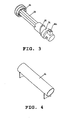
- the photocatalyst reaction unit includes an elongated air duct 21, a photocatalyst coating layer 22 disposed on an interior wall of the air duct 21, two lamp holders 24, at least one ultra violet ray tube 23 mounted on the two lamp holders 24 and a blow guide holder 26 on which a spiral blow guide blade 25 is mounted.
- the air duct 21 is composed of two elongated housings each having a semi-circle section which can be abutted with each other.
- a recess is provided on the left lower side of each of the two semi-circle shaped housings. Accordingly, the recesses provided on the two semicircle shaped housings respectively can be abutted with each other so as to form an air inlet port.
- the interior wall of the air duct 21 can be formed into a smooth surface or an accidented surface with undulations.
- the interior wall of the air duct 21 is formed into an accidented surface with undulations.
- the photocatalyst coating layer 22 is coated onto the accidented surface of the interior wall of the air duct by a spraying or impregnating process. Consequently, the ratio surface area of the photocatalyst coating layer can be effectively increased so that the purifying efficiency can be enhanced.
- Two ends of the air duct 21 are hermetically connected to left and right side plates of the body 1.
- the air duct is provided at the left side thereof with an air inlet port which is in communication with the air outlet port of the forcible convection unit in a tangential direction thereof.
- the air drawn into the air duct 21 can reliably flow along the interior wall of the air duct 21 so as to enhance the contacting between the air and the photocatalyst only by adjusting the blowing speed of the forcible convection unit 3.
- each ultra violet ray tube 23 is arranged in form of a Chinese Character " " .
- Two ends of each ultra violet ray tube 23 are mounted on the lamp holders 24 and are axially disposed inside the air duct 21.
- ultra violet ray emitted from the ultra violet ray tube 23 can be directly incident onto the photocatalyst without blocking so that the catalyst reaction is enhanced into the most desirable state.
- the purifying efficiency of the air cleaning device is further increased.
- the blow guide holder 26 on which a spiral blow guide blade 25 is mounted is provided on the left side plate of the body 1 and located at a position of the air inlet port of the air duct 21. Due to rotation of the blow guide blade 25, the air flows spirally inside the air duct 21. As a result, the time and the chance for which the air contacts with the photocatalyst are improved, thus enhancing purifying efficiency of the air cleaning device of the present invention.
- blow guide holder 26 is provided with a plurality of vent holes 28 which are formed and arranged in the form of a loop.
- a vent opening 261 which is in communication with the vent holes is provided a side wall of the blow guide holder 26.
- the position where the ultra violet ray tubes 23 are located so as to be discharged from the vent opening 261 due to vortex effect of air current (the center of the spiral air current where the pressure is smallest corresponds to the central axis of the air duct 21 .i.e. the position adjacent to where the ultra violet ray tubes 23 are located).
- the time and chance for performing sterilization by the ultra violet ray tubes 23 are increased.
- the air drawn into the air duct is forced toward to the interior wall of the air duct so that the time and chance for which the air contacts with the photocatalyst are increased. As a result, the purifying efficiency of the air cleaning device is further enhanced.
- one of the two lamp holders 24 is connected to the right side plate of the body 1, and the other one is connected to the blow guide holder 26.
Landscapes
- Engineering & Computer Science (AREA)
- Health & Medical Sciences (AREA)
- Chemical & Material Sciences (AREA)
- Mechanical Engineering (AREA)
- General Engineering & Computer Science (AREA)
- Combustion & Propulsion (AREA)
- Epidemiology (AREA)
- Life Sciences & Earth Sciences (AREA)
- Animal Behavior & Ethology (AREA)
- General Health & Medical Sciences (AREA)
- Public Health (AREA)
- Veterinary Medicine (AREA)
- Chemical Kinetics & Catalysis (AREA)
- Disinfection, Sterilisation Or Deodorisation Of Air (AREA)
- Filtering Of Dispersed Particles In Gases (AREA)
Applications Claiming Priority (1)
| Application Number | Priority Date | Filing Date | Title |
|---|---|---|---|
| PCT/CN2002/000922 WO2004059217A1 (en) | 2002-12-30 | 2002-12-30 | Air cleaner |
Publications (2)
| Publication Number | Publication Date |
|---|---|
| EP1598603A1 true EP1598603A1 (de) | 2005-11-23 |
| EP1598603A4 EP1598603A4 (de) | 2007-06-06 |
Family
ID=32661061
Family Applications (1)
| Application Number | Title | Priority Date | Filing Date |
|---|---|---|---|
| EP02808301A Withdrawn EP1598603A4 (de) | 2002-12-30 | 2002-12-30 | Luftreiniger |
Country Status (4)
| Country | Link |
|---|---|
| EP (1) | EP1598603A4 (de) |
| CN (1) | CN1301386C (de) |
| AU (1) | AU2002357559A1 (de) |
| WO (1) | WO2004059217A1 (de) |
Families Citing this family (8)
| Publication number | Priority date | Publication date | Assignee | Title |
|---|---|---|---|---|
| CN101244375B (zh) * | 2008-03-14 | 2010-06-09 | 陕西师范大学 | 磁强化光催化风轮与空气净化方法 |
| CN106581709A (zh) * | 2016-12-31 | 2017-04-26 | 合肥优亿科机电科技有限公司 | 用于医疗器械灭菌设备中的大气等离子体灭菌器 |
| CN106492247A (zh) * | 2016-12-31 | 2017-03-15 | 合肥优亿科机电科技有限公司 | 便捷型大气等离子体灭菌设备 |
| US10871295B2 (en) * | 2017-08-30 | 2020-12-22 | Seoul Viosys Co., Ltd. | Air cleaning module |
| CN107687680A (zh) * | 2017-10-10 | 2018-02-13 | 默克环保科技(湖南)有限公司 | 一种过滤分解除臭机 |
| TWI744653B (zh) * | 2019-06-21 | 2021-11-01 | 財團法人工業技術研究院 | 除菌裝置及其方法 |
| CN110772896B (zh) * | 2019-11-19 | 2024-09-24 | 广西南宁都宁通风防护设备有限公司 | 一种空气过滤吸收器 |
| CN111744360A (zh) * | 2020-07-03 | 2020-10-09 | 龙岩学院 | 一种光触媒空气清净装置 |
Family Cites Families (10)
| Publication number | Priority date | Publication date | Assignee | Title |
|---|---|---|---|---|
| US3757495A (en) * | 1971-12-30 | 1973-09-11 | W Sievers | Portable air purifier |
| CN2114787U (zh) * | 1991-12-13 | 1992-09-02 | 中国科学院兰州化学物理研究所 | 光催化空气净化器 |
| CN2164518Y (zh) * | 1993-05-28 | 1994-05-11 | 陕西省眉县夏汇电器厂 | 光催化空气净化机 |
| JPH11253545A (ja) * | 1998-03-10 | 1999-09-21 | Aiwa Co Ltd | 空気清浄装置 |
| CN2333944Y (zh) * | 1998-07-10 | 1999-08-18 | 福州大学化肥催化剂国家工程研究中心 | 臭氧光催化空气净化器 |
| JP2001029747A (ja) * | 1999-07-26 | 2001-02-06 | Shimadzu Corp | 光化学酸化分解方法及び光化学酸化分解反応器 |
| CN2396820Y (zh) * | 1999-11-11 | 2000-09-20 | 李植晋 | 具有光催化功能的空气杀菌、净化装置 |
| JP2002058728A (ja) * | 2000-08-22 | 2002-02-26 | Yoshikazu Uchiumi | 脱臭装置 |
| JP2002346318A (ja) * | 2001-05-25 | 2002-12-03 | Kondo Harumochi | エアフィルタ |
| CN2508848Y (zh) * | 2001-11-05 | 2002-09-04 | 李彦 | 大流量管式光催化反应器 |
-
2002
- 2002-12-30 WO PCT/CN2002/000922 patent/WO2004059217A1/zh not_active Ceased
- 2002-12-30 EP EP02808301A patent/EP1598603A4/de not_active Withdrawn
- 2002-12-30 AU AU2002357559A patent/AU2002357559A1/en not_active Abandoned
- 2002-12-30 CN CNB028301250A patent/CN1301386C/zh not_active Expired - Fee Related
Also Published As
| Publication number | Publication date |
|---|---|
| EP1598603A4 (de) | 2007-06-06 |
| CN1720417A (zh) | 2006-01-11 |
| CN1301386C (zh) | 2007-02-21 |
| AU2002357559A1 (en) | 2004-07-22 |
| HK1077623A1 (en) | 2006-02-17 |
| WO2004059217A1 (en) | 2004-07-15 |
Similar Documents
| Publication | Publication Date | Title |
|---|---|---|
| US7329313B2 (en) | Air cleaner | |
| CN101535730B (zh) | 空气净化器 | |
| US20220404045A1 (en) | Air cleaner | |
| CN204739688U (zh) | 空气净化器 | |
| CN105987446A (zh) | 包括uv发光二极管和光催化过滤器的紧凑型空气净化器 | |
| CN114521224A (zh) | 空气净化器 | |
| US20060159598A1 (en) | Air cleaner | |
| KR102664427B1 (ko) | 공기청정기용 광촉매 메디아모듈 | |
| US20210269965A1 (en) | Clothes care apparatus | |
| WO2006118372A1 (en) | Wet type air cleaner | |
| EP1598603A1 (de) | Luftreiniger | |
| KR20200075412A (ko) | 차량용 공기청정기 | |
| KR200207656Y1 (ko) | 공기청정기 | |
| CN204730343U (zh) | 空气净化器 | |
| KR200494084Y1 (ko) | 광촉매필터를 이용한 공기청정기 | |
| KR100527358B1 (ko) | 사이클론을 구비한 공기청정기 | |
| CN204739687U (zh) | 空气净化器 | |
| JP2002078782A (ja) | 空気清浄機 | |
| JP2008531247A (ja) | 湿式空気清浄機 | |
| HK1083886A (en) | Air cleaner | |
| CN219352732U (zh) | 一种宠物清洁器 | |
| CN212644889U (zh) | 室内空气净化装置 | |
| KR200330036Y1 (ko) | 공기청정기 | |
| KR100235088B1 (ko) | 공기청정기 | |
| CN218033575U (zh) | 一种便携式空气净化器 |
Legal Events
| Date | Code | Title | Description |
|---|---|---|---|
| PUAI | Public reference made under article 153(3) epc to a published international application that has entered the european phase |
Free format text: ORIGINAL CODE: 0009012 |
|
| 17P | Request for examination filed |
Effective date: 20050721 |
|
| AK | Designated contracting states |
Kind code of ref document: A1 Designated state(s): AT BE BG CH CY CZ DE DK EE ES FI FR GB GR IE IT LI LU MC NL PT SE SI SK TR |
|
| AX | Request for extension of the european patent |
Extension state: AL LT LV MK RO |
|
| DAX | Request for extension of the european patent (deleted) | ||
| A4 | Supplementary search report drawn up and despatched |
Effective date: 20070507 |
|
| RIC1 | Information provided on ipc code assigned before grant |
Ipc: B01D 53/86 20060101ALI20070427BHEP Ipc: A61L 9/16 20060101ALI20070427BHEP Ipc: A61L 9/20 20060101ALI20070427BHEP Ipc: F24F 3/16 20060101AFI20040716BHEP |
|
| STAA | Information on the status of an ep patent application or granted ep patent |
Free format text: STATUS: THE APPLICATION IS DEEMED TO BE WITHDRAWN |
|
| 18D | Application deemed to be withdrawn |
Effective date: 20080701 |