EP1598567B1 - Verfahren zum Zusammenbau einer Pressniete und Pressniete hergestellt durch ein solches Verfahren - Google Patents
Verfahren zum Zusammenbau einer Pressniete und Pressniete hergestellt durch ein solches Verfahren Download PDFInfo
- Publication number
- EP1598567B1 EP1598567B1 EP05354020A EP05354020A EP1598567B1 EP 1598567 B1 EP1598567 B1 EP 1598567B1 EP 05354020 A EP05354020 A EP 05354020A EP 05354020 A EP05354020 A EP 05354020A EP 1598567 B1 EP1598567 B1 EP 1598567B1
- Authority
- EP
- European Patent Office
- Prior art keywords
- threaded rod
- stud
- rod
- assembly
- crimping
- Prior art date
- Legal status (The legal status is an assumption and is not a legal conclusion. Google has not performed a legal analysis and makes no representation as to the accuracy of the status listed.)
- Expired - Lifetime
Links
Images

Classifications
-
- F—MECHANICAL ENGINEERING; LIGHTING; HEATING; WEAPONS; BLASTING
- F16—ENGINEERING ELEMENTS AND UNITS; GENERAL MEASURES FOR PRODUCING AND MAINTAINING EFFECTIVE FUNCTIONING OF MACHINES OR INSTALLATIONS; THERMAL INSULATION IN GENERAL
- F16B—DEVICES FOR FASTENING OR SECURING CONSTRUCTIONAL ELEMENTS OR MACHINE PARTS TOGETHER, e.g. NAILS, BOLTS, CIRCLIPS, CLAMPS, CLIPS OR WEDGES; JOINTS OR JOINTING
- F16B33/00—Features common to bolt and nut
- F16B33/008—Corrosion preventing means
-
- F—MECHANICAL ENGINEERING; LIGHTING; HEATING; WEAPONS; BLASTING
- F16—ENGINEERING ELEMENTS AND UNITS; GENERAL MEASURES FOR PRODUCING AND MAINTAINING EFFECTIVE FUNCTIONING OF MACHINES OR INSTALLATIONS; THERMAL INSULATION IN GENERAL
- F16B—DEVICES FOR FASTENING OR SECURING CONSTRUCTIONAL ELEMENTS OR MACHINE PARTS TOGETHER, e.g. NAILS, BOLTS, CIRCLIPS, CLAMPS, CLIPS OR WEDGES; JOINTS OR JOINTING
- F16B19/00—Bolts without screw-thread; Pins, including deformable elements; Rivets
- F16B19/04—Rivets; Spigots or the like fastened by riveting
- F16B19/08—Hollow rivets; Multi-part rivets
- F16B19/10—Hollow rivets; Multi-part rivets fastened by expanding mechanically
- F16B19/1027—Multi-part rivets
- F16B19/1036—Blind rivets
- F16B19/1045—Blind rivets fastened by a pull - mandrel or the like
- F16B19/1072—Blind rivets fastened by a pull - mandrel or the like the pull-mandrel or the like comprising a thread and being rotated with respect to the rivet, thereby mechanically expanding and fastening the rivet
-
- F—MECHANICAL ENGINEERING; LIGHTING; HEATING; WEAPONS; BLASTING
- F16—ENGINEERING ELEMENTS AND UNITS; GENERAL MEASURES FOR PRODUCING AND MAINTAINING EFFECTIVE FUNCTIONING OF MACHINES OR INSTALLATIONS; THERMAL INSULATION IN GENERAL
- F16B—DEVICES FOR FASTENING OR SECURING CONSTRUCTIONAL ELEMENTS OR MACHINE PARTS TOGETHER, e.g. NAILS, BOLTS, CIRCLIPS, CLAMPS, CLIPS OR WEDGES; JOINTS OR JOINTING
- F16B33/00—Features common to bolt and nut
- F16B33/02—Shape of thread; Special thread-forms
Definitions
- the invention relates to a method for assembling the components of a crimping pin in a support, the crimping stud having a threaded cylindrical rod, terminated by a head, and a sleeve, connected to the threaded rod by deformation and comprising successively a zone of assembly of the sleeve on the threaded rod, in contact with the head, a zone of recess, intended for the formation of a crimping bead of the stud, and a support flange, the threaded rod comprising, in view of the assembly area, a knurled portion constituted by a plurality of longitudinal grooves.
- the invention also relates to a crimp pin obtained by such an assembly method.
- a crimping stud is a stud intended to be secured by crimping in a thin support.
- the support can be of any kind, in particular metal or plastic.
- the material of the crimping stud may be selected from steel, stainless steel, aluminum and brass.
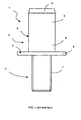
- the crimping pin 1 is conventionally constituted by two components, a threaded rod 2 and a bushing 3.
- the threaded rod 2 may comprise a head 4 and the bushing 3, in contact with the head 4, is consisting of a collar 5 and a shank 6.
- the collar 5 of the sleeve 3 can be of any type, for example flat, milled, elliptical or polygonal, and the shank 6 can be of any type, for example cylindrical, smooth, knurled, hexagonal or semi-hexagonal.
- the bushing 3 is connected to the threaded rod 2, for example, by crimping.
- the crimp pin 1 is then divided into four distinct zones, namely a threaded zone 7 formed on the part of the rod 2 projecting out of the sleeve 3, the flange 5, a chambering zone 8 and an assembly zone 9.
- the threaded zone 7 represents the functional part of the bolt 1 after crimping on a support 14 (FIG. 4) and must be sufficiently strong to be able to undergo without deformation the loads applied to a standard nut screwed onto the rod 2.
- the flange 5 is intended to come into contact with the support 14 (FIG. 4) on which the stud 1 will be installed and to serve as a support for another part, which will subsequently be assembled on the support via, for example, of a nut.
- the chambering zone 8 or crimping area, is intended to deform under the action of an axial force applied to the sleeve 3 via the threaded rod 7. It must be sufficiently plastic and ductile to deform symmetrically, without breaking, under a load adjusted according to the diameter of the thread of the rod 2 and the nature of the material constituting the crimping stud 1. As shown in Figure 4, the chambering zone 8 is transformed, after deformation, in a crimping bead 15, which pinches the support 14 against the flange 5, thus ensuring the maintenance of the stud 1 on the support 14.
- the assembly zone 9 represents the connection zone between the bushing 3 and the threaded rod 2 of the crimping stud 1. It must make it possible to guarantee the mechanical strength of the crimping stud 1 in use. The assembly of the sleeve 3 on the threaded rod 2 must be as strong as possible.
- a first known assembly technique is to weld the sleeve 3 on the rod 2, at the assembly zone 9, before carrying out a surface treatment, including anti-corrosion treatment, on the crimping pin 1
- the stud 1 does not have good corrosion resistance characteristics because the rod 2 and the bushing 3 have been assembled before being treated.
- the welding process attenuates the mechanical performance of the stud 1.
- Crimping is another known assembly technique.
- the threaded rod 2 then has a groove and the material of the sleeve 3 is inserted into this groove to lock the sleeve 3 in translation and rotation.
- document FR-A-2699617 describes a crimping stud consisting of a bushing screwed onto a threaded element.
- the two components of the stud are crimped by rotating knobs.
- the threaded element comprises a groove and crimping causes the appearance of a crimping ring, intended to lock in rotation the sleeve on the threaded element.
- the mechanical strength of the sleeve on the threaded element is not optimal.
- US-A-4,007,659 discloses another technique for assembling the components of the crimp stud.
- the fastening of the socket on the threaded rod is formed by the complementary shape of the lower end of the sleeve and the corresponding part of the rod.
- a knurled portion on the rod fills with material to ensure the holding of the sleeve relative to the rod.
- the mechanical strength of a stud assembled according to this method is not optimal, the quality of assembly of the components of the stud depending on the crimping operation on the support.
- the object of the invention is to overcome the aforementioned drawbacks and relates to a method of assembling the components of a crimping pin making it possible to obtain a crimping stud with optimum mechanical holding in rotation and in extraction, while being independent of the operation of crimping the stud on the support.
- this object is achieved by an assembly method and a crimp pin according to the appended claims.
- the object is achieved, in particular, by the fact that the longitudinal grooves are formed on the threading of the rod, so as to form a plurality of helical grooves, and by the fact that the assembly of the bushing on the threaded rod is performed by a necking method, before crimping in said support.
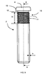
- the crimping stud 1 is conventionally constituted of a threaded rod 2, terminated by the head 4, and of the bushing 3, comprising the bearing flange 5, the chambering zone 8, intended to be transformed in crimping bead, and the assembly zone 9, in contact with the head 4 of the threaded rod 2.
- the stud 1 thus comprises successively four distinct zones, namely the threaded zone 7, which is its functional part in use, the flange 5, the chambering zone 8 and the assembly zone 9.
- the bushing 3 is connected to the threaded rod 2 by deformation at the assembly zone 9.
- the head 4 of the threaded rod 2 preferably comprises a chamfer 13 of substantially frustoconical shape, also called inlet cone.
- the chamfer 13 facilitates the introduction of the stud 1 in a support.
- the diameter of the head 4 of the threaded rod 2 is substantially identical to that of the assembly zone 9 of the sleeve 3, after deformation of the sleeve 3 on the threaded rod 2.
- the head 4 prevents the sleeve 3 from disengaging from the threaded rod 2.
- the head 4 thus guarantees an anti-extraction effect.
- the threaded rod 2 and the sleeve 3 are made of a material selected from steel, stainless steel, aluminum or brass.
- the sleeve 3 may be, for example, flat head, countersunk, elliptical or polygonal and cylindrical barrel, knurled, hexagonal or semi-hexagonal.
- the bushing 3 preferably has a knurled or hexagonal barrel, so that the recessing zone 8 prevents rotation of the bushing 3 in the support 14 (FIG. 4), after crimping the stud 1.
- the rod 2 threaded over its entire length comprises a knurled portion 10, consisting of a plurality of longitudinal grooves 11, made on the thread of the rod 2, so as to form a plurality of helical grooves.
- the grooves 11 are all parallel to the axis AA of the threaded rod 2.
- the knurled portion 10 is located opposite the assembly zone 9 of the sleeve 3 and can extend under part of the chambering zone 8 of the the socket 3.
- the helical grooves constituted by the characteristic interlacing of the threading of the rod 2 and the longitudinal grooves 11, have the role of optimizing the assembly of the bushing 3 on the threaded rod 2.
- the longitudinal grooves 11 guarantee an effect of anti-rotation of the sleeve 3 on the threaded rod 2 and the helical grooves ensure an anti-extraction effect of the sleeve 3.
- the knurled portion 10 therefore ensures good mechanical strength of the stud 1 in use.
- the threaded rod 2 also comprises a groove 12, made between the head 4 and the knurled portion 10 of the threaded rod 2.
- the function of the groove 12 is to improve the assembly of the sleeve 3 on the threaded rod 2 and to guarantee an anti-extraction effect of the threaded rod 2.
- the method of manufacturing the crimping stud 1 is to manufacture separately the threaded rod 2 and the sleeve 3, to apply a surface treatment, including anti-corrosion treatment, and then to assemble by deformation.
- the assembly of the sleeve 3 on the threaded rod 2 can be performed by a necking method, for example, by crimping, stamping or hammering.
- the crimping pin 1 thus obtained is a ready-to-use product which exhibits good resistance to corrosion, since its two constituent components, namely the threaded rod 2 and the sleeve 3, have been treated separately.
- the method of assembling the sleeve 3 on the threaded rod 2 is preferably carried out by a stamping technique.
- the sleeve 3 is crimped by two dies on the threaded rod 2 in one or more operations, at different angles, in order to reduce the outer diameter of the sleeve 3.
- stamping the sleeve 3 on the threaded rod 2 the material constituting the sleeve 3 penetrates, on the one hand, in the knurled portion 10 of the threaded rod 2 and, on the other hand, fills the groove 12 under the head 4 of the threaded rod 2 ( Figure 2).
- This work hardening operation is intended to harden the assembly area 9.
- the hardened material and the particular design of the threaded rod 2 and the knurled portion 10 are sufficient to obtain a very strong mechanical assembly in rotation and extraction of the two constituent components of the stud 1.
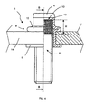
- the method of assembling the components of the crimping stud 1 is performed before the crimping of the stud 1 on the support 14, to ensure optimum mechanical strength to the stud 1.
- the stud 1 is crimped on the support 14.
- the chambering zone 8 has been transformed into a crimping bead 15, whose function is to hold the stud 1 on the support 14.
- the support 14 is therefore maintained between the bead 15 and the support flange 5.
- the knurled portion 10 of the threaded rod 2 preferably has a height H corresponding approximately to the distance separating the groove 12 from the threaded rod 2 of the support 14, after crimping the stud 1. , the height H must in no case extend below the collar 5 after crimping, that is to say on the functional part of the stud 1.
- the crimping stud 1 thus has the following advantages. At the end of the assembly of the sleeve 3 on the threaded rod 2, before crimping on the support 14, the stud 1 is a finished product, ready to pack, because the anti-corrosion treatment was carried out beforehand. In addition, the shrinkage performed for the assembly of the sleeve 3 on the rod 2 facilitates the introduction of the stud 1 in the predetermined housing applications specific to each customer, especially in the case of automatic installation of the stud 1.
- the stamping assembly provides superior mechanical strength to a welded joint or other localized crimping principle with minimal dispersion and variability.
- the installation of the stud 1 on the support 14 is of better quality, because the assembly area 9 is more resistant to laying efforts.
- the assembly of the components of the stud 1 being made before crimping on the support 14, the stud 1 is not likely to be damaged by the crimping on the support 14.
- the mechanical strength of the stud 1 is optimized, thanks to the throat 12 and the knurled portion 10, made on the thread of the rod 2 opposite the assembly zone 9.
- the crimp pin 1 is particularly suitable for the automotive industry, which wishes to use crimp pins having the advantages described above, namely a good resistance to corrosion and good mechanical resistance to stresses.
Landscapes
- Engineering & Computer Science (AREA)
- General Engineering & Computer Science (AREA)
- Mechanical Engineering (AREA)
- Insertion Pins And Rivets (AREA)
- Forging (AREA)
- Connection Of Plates (AREA)
- Mutual Connection Of Rods And Tubes (AREA)
Claims (6)
- Verfahren zum Verbinden der Bestandteile einer Nietschraube (1), die in einen Träger (14) gekrimpt werden soll, wobei die Nietschraube (1) einen gewindeten zylindrischen Schaft (2), an dessen Ende ein Kopf (4) sitzt, und eine Hülse (3) umfasst, die mit dem gewindeten Schaft (2) durch Verformung verbunden wurde, und die nacheinander einen mit dem Kopf (4) in Kontakt stehenden Verbindungsbereich (9), zum verbinden der Hülse (3) auf dem gewindeten Schaft (2), eine Stauchzone (8), die zur Herstellung eines Krimpwulstes (15) der Nietschraube (1) bestimmt ist, und einen Auflagekragen (5) umfasst, wobei der gewindete Schaft (2) gegenüber dem Verbindungsbereich (9) einen gerändelten Bereich (10) aufweist, der von einer Mehrzahl Längsrillen (11) gebildet wird, Verbindungsverfahren, das dadurch gekennzeichnet ist, dass die Längsrillen (11) auf dem Gewinde des Schafts (2) angebracht werden, um eine Mehrzahl spiralförmiger Rillen zu bilden, sowie dadurch, dass die Befestigung der Hülse (3) auf dem gewindeten Schaft (2) durch ein Querschnittsverminderungsverfahren vor dem Krimpen in den genannten Träger (14) erfolgt.
- Verbindungsverfahren nach Anspruch 1, dadurch gekennzeichnet, dass es eine Rostschutzbehandlung des gewindeten Schafts (2) und der Hülse (3) vor dem Verbinden der Hülse (3) mit dem gewindeten Schaft (2) umfasst.
- Nietschraube (1), die mittels eines Verbindungsverfahrens nach einem der Ansprüche 1 und 2 hergestellt wurde, dadurch gekennzeichnet, dass sie eine Nut (12) umfasst, die zwischen dem Kopf (4) und dem gerändelten Bereich (10) des gewindeten Schafts (2) angebracht ist.
- Nietschraube nach Anspruch 3, dadurch gekennzeichnet, dass der Durchmesser des Kopfes (4) des gewindeten Schafts (2) im Wesentlichen identisch ist mit dem des Verbindungsbereichs (9) der Hülse (3) nach dem Krimpen der Hülse (3) auf dem gewindeten Schaft (2).
- Nietschraube nach einem der Ansprüche 3 und 4, dadurch gekennzeichnet, dass der Kopf (4) des gewindeten Schafts (2) eine im Wesentlichen kegelstumpfförmige Abschrägung (13) umfasst.
- Nietschraube nach einem der Ansprüche 3 bis 5, dadurch gekennzeichnet, dass der gewindete Schaft (2) und die Hülse (3) aus einem Material gefertigt sind, das aus Stahl, Inoxstahl, Aluminium oder Messing ausgewählt ist.
Priority Applications (1)
| Application Number | Priority Date | Filing Date | Title |
|---|---|---|---|
| PL05354020T PL1598567T3 (pl) | 2004-05-19 | 2005-05-16 | Sposób montażu kołka zaciskowego i kołek zaciskowy otrzymany przy zastosowaniu tego sposobu |
Applications Claiming Priority (2)
| Application Number | Priority Date | Filing Date | Title |
|---|---|---|---|
| FR0405476 | 2004-05-19 | ||
| FR0405476A FR2870573A1 (fr) | 2004-05-19 | 2004-05-19 | Goujon a sertir et procede de fabrication |
Publications (2)
| Publication Number | Publication Date |
|---|---|
| EP1598567A1 EP1598567A1 (de) | 2005-11-23 |
| EP1598567B1 true EP1598567B1 (de) | 2007-03-21 |
Family
ID=34942680
Family Applications (1)
| Application Number | Title | Priority Date | Filing Date |
|---|---|---|---|
| EP05354020A Expired - Lifetime EP1598567B1 (de) | 2004-05-19 | 2005-05-16 | Verfahren zum Zusammenbau einer Pressniete und Pressniete hergestellt durch ein solches Verfahren |
Country Status (7)
| Country | Link |
|---|---|
| EP (1) | EP1598567B1 (de) |
| AT (1) | ATE357608T1 (de) |
| DE (1) | DE602005000723T2 (de) |
| ES (1) | ES2282984T3 (de) |
| FR (1) | FR2870573A1 (de) |
| PL (1) | PL1598567T3 (de) |
| PT (1) | PT1598567E (de) |
Families Citing this family (3)
| Publication number | Priority date | Publication date | Assignee | Title |
|---|---|---|---|---|
| GB2446815C (en) * | 2006-12-20 | 2012-10-03 | Avdel Gb Ltd | Blind stud insert. |
| FR2963576B1 (fr) * | 2010-08-05 | 2012-09-07 | Bollhoff Otalu Sa | Dispositif a element spherique a sertir et procede de sertissage |
| FR3022962B1 (fr) | 2014-06-27 | 2017-02-10 | Bollhoff Otalu Sa | Piece a sertir sur un support, dispositif comprenant une telle piece et procedes de fabrication d'une telle piece et d'un tel dispositif |
Family Cites Families (3)
| Publication number | Priority date | Publication date | Assignee | Title |
|---|---|---|---|---|
| US4007659A (en) * | 1972-03-27 | 1977-02-15 | Vsi Corporation | Fastener insert with improved anti-rotation and pull-out characteristics |
| FR2699617B1 (fr) * | 1992-12-21 | 1995-02-17 | Simaf | Insert à douille et élément fileté. |
| JPH11270535A (ja) * | 1998-03-23 | 1999-10-05 | Pop Rivet Fastener Kk | 締結具 |
-
2004
- 2004-05-19 FR FR0405476A patent/FR2870573A1/fr active Pending
-
2005
- 2005-05-16 DE DE602005000723T patent/DE602005000723T2/de not_active Expired - Lifetime
- 2005-05-16 EP EP05354020A patent/EP1598567B1/de not_active Expired - Lifetime
- 2005-05-16 PT PT05354020T patent/PT1598567E/pt unknown
- 2005-05-16 ES ES05354020T patent/ES2282984T3/es not_active Expired - Lifetime
- 2005-05-16 PL PL05354020T patent/PL1598567T3/pl unknown
- 2005-05-16 AT AT05354020T patent/ATE357608T1/de not_active IP Right Cessation
Also Published As
| Publication number | Publication date |
|---|---|
| PT1598567E (pt) | 2007-06-15 |
| EP1598567A1 (de) | 2005-11-23 |
| DE602005000723T2 (de) | 2007-12-06 |
| PL1598567T3 (pl) | 2007-08-31 |
| DE602005000723D1 (de) | 2007-05-03 |
| ES2282984T3 (es) | 2007-10-16 |
| FR2870573A1 (fr) | 2005-11-25 |
| ATE357608T1 (de) | 2007-04-15 |
Similar Documents
| Publication | Publication Date | Title |
|---|---|---|
| EP1462208B1 (de) | Verfahren zur Herstellung einer Krimpmutter und durch dieses Verfahren hergestellte Krimpmutter | |
| EP2265828B1 (de) | Montageverfahren für verbundwerkstoffe und nietelement zu seiner durchführung | |
| EP2960531B1 (de) | Werkstück zum festklemmen auf einer halterung, vorrichtung, die ein solches werkstück umfasst, und herstellungsverfahren eines solchen werkstücks und einer solchen vorrichtung | |
| FR2963576A1 (fr) | Dispositif a element spherique a sertir et procede de sertissage | |
| EP3366932B1 (de) | Einsatz zum crimpen, befestigungselement und -einheit, die einen solchen einsatz umfassen, und herstellungsverfahren von solchen teilen | |
| EP2552622B1 (de) | Niet und nietsetzvorrichtung | |
| WO2008102094A2 (fr) | Rivet aveugle hautes performances notamment pour fixation de structure | |
| EP1598567B1 (de) | Verfahren zum Zusammenbau einer Pressniete und Pressniete hergestellt durch ein solches Verfahren | |
| EP1941168B1 (de) | Blindniet, insbesondere zur befestigung einer struktur und verfahren zu dessen einführung | |
| EP0325069A1 (de) | Befestigungsmutter | |
| EP1958715A1 (de) | Verfahren zum Zusammenbau von mindestens zwei Elementen mit Hilfe eines Blindniets | |
| FR2945088A1 (fr) | Systeme d'ecrou noye a sertir en aveugle avec axe ajustable | |
| FR2699617A1 (fr) | Insert à douille et élément fileté. | |
| FR2642802A1 (fr) | Ecrou a montage en aveugle et par sertissage sur une paroi quelconque | |
| WO2025153782A1 (fr) | Element de jonction assurant un assemblage multi-materiaux de trois epaisseurs | |
| FR2861146A1 (fr) | Ecrou noye a sertir | |
| EP1873406A1 (de) | Bördelmutter | |
| EP0864798B1 (de) | Verfahren zum Verbinden eines Schlauches mit einem Rohr, Kupplung und Befestigungsring zum Durchführen dieses Verfahrens | |
| FR2761425A1 (fr) | Vis a entretoise imperdable et compressible | |
| FR2924630A1 (fr) | Procede de sertissage d'un support metallique muni d'une ouverture avec un insert | |
| EP2336579A1 (de) | Einsatz mit Innengewinde für Blindmontage am Ende eines Rohrs, und Blindmontageverfahren | |
| FR2652773A1 (fr) | Procede d'obtention d'une douille a collerette, notamment destinee a la liaison d'un tuyau sur un raccord, et dispositif pour sa mise en óoeuvre. | |
| FR3082131A1 (fr) | Procede d'assemblage d'une premiere piece et d'une deuxieme piece par l'intermediaire d'un insert | |
| FR2959431A1 (fr) | Dispositif d'assemblage a sertir | |
| FR2895291A1 (fr) | Procede de realisation d'une piece support et piece obtenue |
Legal Events
| Date | Code | Title | Description |
|---|---|---|---|
| PUAI | Public reference made under article 153(3) epc to a published international application that has entered the european phase |
Free format text: ORIGINAL CODE: 0009012 |
|
| AK | Designated contracting states |
Kind code of ref document: A1 Designated state(s): AT BE BG CH CY CZ DE DK EE ES FI FR GB GR HU IE IS IT LI LT LU MC NL PL PT RO SE SI SK TR |
|
| AX | Request for extension of the european patent |
Extension state: AL BA HR LV MK YU |
|
| 17P | Request for examination filed |
Effective date: 20060420 |
|
| AKX | Designation fees paid |
Designated state(s): AT BE BG CH CY CZ DE DK EE ES FI FR GB GR HU IE IS IT LI LT LU MC NL PL PT RO SE SI SK TR |
|
| GRAP | Despatch of communication of intention to grant a patent |
Free format text: ORIGINAL CODE: EPIDOSNIGR1 |
|
| GRAS | Grant fee paid |
Free format text: ORIGINAL CODE: EPIDOSNIGR3 |
|
| GRAA | (expected) grant |
Free format text: ORIGINAL CODE: 0009210 |
|
| AK | Designated contracting states |
Kind code of ref document: B1 Designated state(s): AT BE BG CH CY CZ DE DK EE ES FI FR GB GR HU IE IS IT LI LT LU MC NL PL PT RO SE SI SK TR |
|
| PG25 | Lapsed in a contracting state [announced via postgrant information from national office to epo] |
Ref country code: NL Free format text: LAPSE BECAUSE OF FAILURE TO SUBMIT A TRANSLATION OF THE DESCRIPTION OR TO PAY THE FEE WITHIN THE PRESCRIBED TIME-LIMIT Effective date: 20070321 Ref country code: SI Free format text: LAPSE BECAUSE OF FAILURE TO SUBMIT A TRANSLATION OF THE DESCRIPTION OR TO PAY THE FEE WITHIN THE PRESCRIBED TIME-LIMIT Effective date: 20070321 Ref country code: FI Free format text: LAPSE BECAUSE OF FAILURE TO SUBMIT A TRANSLATION OF THE DESCRIPTION OR TO PAY THE FEE WITHIN THE PRESCRIBED TIME-LIMIT Effective date: 20070321 Ref country code: AT Free format text: LAPSE BECAUSE OF FAILURE TO SUBMIT A TRANSLATION OF THE DESCRIPTION OR TO PAY THE FEE WITHIN THE PRESCRIBED TIME-LIMIT Effective date: 20070321 |
|
| REG | Reference to a national code |
Ref country code: GB Ref legal event code: FG4D Free format text: NOT ENGLISH |
|
| REG | Reference to a national code |
Ref country code: CH Ref legal event code: EP |
|
| REF | Corresponds to: |
Ref document number: 602005000723 Country of ref document: DE Date of ref document: 20070503 Kind code of ref document: P |
|
| REG | Reference to a national code |
Ref country code: IE Ref legal event code: FG4D Free format text: LANGUAGE OF EP DOCUMENT: FRENCH |
|
| GBT | Gb: translation of ep patent filed (gb section 77(6)(a)/1977) |
Effective date: 20070522 |
|
| REG | Reference to a national code |
Ref country code: PT Ref legal event code: SC4A Free format text: AVAILABILITY OF NATIONAL TRANSLATION Effective date: 20070604 |
|
| PG25 | Lapsed in a contracting state [announced via postgrant information from national office to epo] |
Ref country code: SE Free format text: LAPSE BECAUSE OF FAILURE TO SUBMIT A TRANSLATION OF THE DESCRIPTION OR TO PAY THE FEE WITHIN THE PRESCRIBED TIME-LIMIT Effective date: 20070621 |
|
| PG25 | Lapsed in a contracting state [announced via postgrant information from national office to epo] |
Ref country code: IS Free format text: LAPSE BECAUSE OF FAILURE TO SUBMIT A TRANSLATION OF THE DESCRIPTION OR TO PAY THE FEE WITHIN THE PRESCRIBED TIME-LIMIT Effective date: 20070721 |
|
| REG | Reference to a national code |
Ref country code: PL Ref legal event code: T3 |
|
| NLV1 | Nl: lapsed or annulled due to failure to fulfill the requirements of art. 29p and 29m of the patents act | ||
| REG | Reference to a national code |
Ref country code: ES Ref legal event code: FG2A Ref document number: 2282984 Country of ref document: ES Kind code of ref document: T3 |
|
| PG25 | Lapsed in a contracting state [announced via postgrant information from national office to epo] |
Ref country code: SK Free format text: LAPSE BECAUSE OF FAILURE TO SUBMIT A TRANSLATION OF THE DESCRIPTION OR TO PAY THE FEE WITHIN THE PRESCRIBED TIME-LIMIT Effective date: 20070321 |
|
| REG | Reference to a national code |
Ref country code: IE Ref legal event code: FD4D |
|
| BERE | Be: lapsed |
Owner name: BOLLHOFF OTALU S.A. Effective date: 20070531 |
|
| PG25 | Lapsed in a contracting state [announced via postgrant information from national office to epo] |
Ref country code: RO Free format text: LAPSE BECAUSE OF FAILURE TO SUBMIT A TRANSLATION OF THE DESCRIPTION OR TO PAY THE FEE WITHIN THE PRESCRIBED TIME-LIMIT Effective date: 20070321 |
|
| PLBE | No opposition filed within time limit |
Free format text: ORIGINAL CODE: 0009261 |
|
| STAA | Information on the status of an ep patent application or granted ep patent |
Free format text: STATUS: NO OPPOSITION FILED WITHIN TIME LIMIT |
|
| PG25 | Lapsed in a contracting state [announced via postgrant information from national office to epo] |
Ref country code: IE Free format text: LAPSE BECAUSE OF FAILURE TO SUBMIT A TRANSLATION OF THE DESCRIPTION OR TO PAY THE FEE WITHIN THE PRESCRIBED TIME-LIMIT Effective date: 20070321 Ref country code: MC Free format text: LAPSE BECAUSE OF NON-PAYMENT OF DUE FEES Effective date: 20070531 Ref country code: DK Free format text: LAPSE BECAUSE OF FAILURE TO SUBMIT A TRANSLATION OF THE DESCRIPTION OR TO PAY THE FEE WITHIN THE PRESCRIBED TIME-LIMIT Effective date: 20070321 |
|
| 26N | No opposition filed |
Effective date: 20071227 |
|
| PG25 | Lapsed in a contracting state [announced via postgrant information from national office to epo] |
Ref country code: BE Free format text: LAPSE BECAUSE OF NON-PAYMENT OF DUE FEES Effective date: 20070531 Ref country code: LT Free format text: LAPSE BECAUSE OF FAILURE TO SUBMIT A TRANSLATION OF THE DESCRIPTION OR TO PAY THE FEE WITHIN THE PRESCRIBED TIME-LIMIT Effective date: 20070321 |
|
| PG25 | Lapsed in a contracting state [announced via postgrant information from national office to epo] |
Ref country code: GR Free format text: LAPSE BECAUSE OF FAILURE TO SUBMIT A TRANSLATION OF THE DESCRIPTION OR TO PAY THE FEE WITHIN THE PRESCRIBED TIME-LIMIT Effective date: 20070622 |
|
| PG25 | Lapsed in a contracting state [announced via postgrant information from national office to epo] |
Ref country code: EE Free format text: LAPSE BECAUSE OF FAILURE TO SUBMIT A TRANSLATION OF THE DESCRIPTION OR TO PAY THE FEE WITHIN THE PRESCRIBED TIME-LIMIT Effective date: 20070321 |
|
| PG25 | Lapsed in a contracting state [announced via postgrant information from national office to epo] |
Ref country code: CY Free format text: LAPSE BECAUSE OF FAILURE TO SUBMIT A TRANSLATION OF THE DESCRIPTION OR TO PAY THE FEE WITHIN THE PRESCRIBED TIME-LIMIT Effective date: 20070321 |
|
| PG25 | Lapsed in a contracting state [announced via postgrant information from national office to epo] |
Ref country code: BG Free format text: LAPSE BECAUSE OF FAILURE TO SUBMIT A TRANSLATION OF THE DESCRIPTION OR TO PAY THE FEE WITHIN THE PRESCRIBED TIME-LIMIT Effective date: 20070621 Ref country code: LU Free format text: LAPSE BECAUSE OF NON-PAYMENT OF DUE FEES Effective date: 20070516 |
|
| PG25 | Lapsed in a contracting state [announced via postgrant information from national office to epo] |
Ref country code: HU Free format text: LAPSE BECAUSE OF FAILURE TO SUBMIT A TRANSLATION OF THE DESCRIPTION OR TO PAY THE FEE WITHIN THE PRESCRIBED TIME-LIMIT Effective date: 20070922 Ref country code: TR Free format text: LAPSE BECAUSE OF FAILURE TO SUBMIT A TRANSLATION OF THE DESCRIPTION OR TO PAY THE FEE WITHIN THE PRESCRIBED TIME-LIMIT Effective date: 20070321 |
|
| REG | Reference to a national code |
Ref country code: CH Ref legal event code: PL |
|
| PG25 | Lapsed in a contracting state [announced via postgrant information from national office to epo] |
Ref country code: LI Free format text: LAPSE BECAUSE OF NON-PAYMENT OF DUE FEES Effective date: 20090531 Ref country code: CH Free format text: LAPSE BECAUSE OF NON-PAYMENT OF DUE FEES Effective date: 20090531 |
|
| REG | Reference to a national code |
Ref country code: FR Ref legal event code: PLFP Year of fee payment: 12 |
|
| REG | Reference to a national code |
Ref country code: FR Ref legal event code: PLFP Year of fee payment: 13 |
|
| REG | Reference to a national code |
Ref country code: FR Ref legal event code: PLFP Year of fee payment: 14 |
|
| PGFP | Annual fee paid to national office [announced via postgrant information from national office to epo] |
Ref country code: CZ Payment date: 20240313 Year of fee payment: 20 |
|
| PGFP | Annual fee paid to national office [announced via postgrant information from national office to epo] |
Ref country code: PL Payment date: 20240228 Year of fee payment: 20 |
|
| PGFP | Annual fee paid to national office [announced via postgrant information from national office to epo] |
Ref country code: GB Payment date: 20240528 Year of fee payment: 20 |
|
| PGFP | Annual fee paid to national office [announced via postgrant information from national office to epo] |
Ref country code: ES Payment date: 20240607 Year of fee payment: 20 |
|
| PGFP | Annual fee paid to national office [announced via postgrant information from national office to epo] |
Ref country code: IT Payment date: 20240411 Year of fee payment: 20 Ref country code: FR Payment date: 20240528 Year of fee payment: 20 |
|
| PGFP | Annual fee paid to national office [announced via postgrant information from national office to epo] |
Ref country code: PT Payment date: 20240516 Year of fee payment: 20 |
|
| PGFP | Annual fee paid to national office [announced via postgrant information from national office to epo] |
Ref country code: DE Payment date: 20240716 Year of fee payment: 20 |
|
| REG | Reference to a national code |
Ref country code: DE Ref legal event code: R071 Ref document number: 602005000723 Country of ref document: DE |
|
| REG | Reference to a national code |
Ref country code: ES Ref legal event code: FD2A Effective date: 20250526 |
|
| REG | Reference to a national code |
Ref country code: GB Ref legal event code: PE20 Expiry date: 20250515 |
|
| PG25 | Lapsed in a contracting state [announced via postgrant information from national office to epo] |
Ref country code: ES Free format text: LAPSE BECAUSE OF EXPIRATION OF PROTECTION Effective date: 20250517 Ref country code: GB Free format text: LAPSE BECAUSE OF EXPIRATION OF PROTECTION Effective date: 20250515 |
|
| PG25 | Lapsed in a contracting state [announced via postgrant information from national office to epo] |
Ref country code: PT Free format text: LAPSE BECAUSE OF EXPIRATION OF PROTECTION Effective date: 20250527 |
|
| PG25 | Lapsed in a contracting state [announced via postgrant information from national office to epo] |
Ref country code: CZ Free format text: LAPSE BECAUSE OF EXPIRATION OF PROTECTION Effective date: 20250516 |