EP1598555B1 - Motor-Pumpeneinheit mit Mitteln zur Begrenzung des von der Pumpe erzeugten Hydraulikfluiddrucks - Google Patents
Motor-Pumpeneinheit mit Mitteln zur Begrenzung des von der Pumpe erzeugten Hydraulikfluiddrucks Download PDFInfo
- Publication number
- EP1598555B1 EP1598555B1 EP20050291034 EP05291034A EP1598555B1 EP 1598555 B1 EP1598555 B1 EP 1598555B1 EP 20050291034 EP20050291034 EP 20050291034 EP 05291034 A EP05291034 A EP 05291034A EP 1598555 B1 EP1598555 B1 EP 1598555B1
- Authority
- EP
- European Patent Office
- Prior art keywords
- motor
- lim
- pump
- limiting
- current
- Prior art date
- Legal status (The legal status is an assumption and is not a legal conclusion. Google has not performed a legal analysis and makes no representation as to the accuracy of the status listed.)
- Active
Links
Images


Classifications
-
- F—MECHANICAL ENGINEERING; LIGHTING; HEATING; WEAPONS; BLASTING
- F04—POSITIVE - DISPLACEMENT MACHINES FOR LIQUIDS; PUMPS FOR LIQUIDS OR ELASTIC FLUIDS
- F04B—POSITIVE-DISPLACEMENT MACHINES FOR LIQUIDS; PUMPS
- F04B49/00—Control, e.g. of pump delivery, or pump pressure of, or safety measures for, machines, pumps, or pumping installations, not otherwise provided for, or of interest apart from, groups F04B1/00 - F04B47/00
- F04B49/06—Control using electricity
-
- F—MECHANICAL ENGINEERING; LIGHTING; HEATING; WEAPONS; BLASTING
- F04—POSITIVE - DISPLACEMENT MACHINES FOR LIQUIDS; PUMPS FOR LIQUIDS OR ELASTIC FLUIDS
- F04B—POSITIVE-DISPLACEMENT MACHINES FOR LIQUIDS; PUMPS
- F04B2203/00—Motor parameters
- F04B2203/02—Motor parameters of rotating electric motors
- F04B2203/0201—Current
-
- F—MECHANICAL ENGINEERING; LIGHTING; HEATING; WEAPONS; BLASTING
- F04—POSITIVE - DISPLACEMENT MACHINES FOR LIQUIDS; PUMPS FOR LIQUIDS OR ELASTIC FLUIDS
- F04B—POSITIVE-DISPLACEMENT MACHINES FOR LIQUIDS; PUMPS
- F04B2205/00—Fluid parameters
- F04B2205/05—Pressure after the pump outlet
-
- F—MECHANICAL ENGINEERING; LIGHTING; HEATING; WEAPONS; BLASTING
- F04—POSITIVE - DISPLACEMENT MACHINES FOR LIQUIDS; PUMPS FOR LIQUIDS OR ELASTIC FLUIDS
- F04B—POSITIVE-DISPLACEMENT MACHINES FOR LIQUIDS; PUMPS
- F04B2205/00—Fluid parameters
- F04B2205/06—Pressure in a (hydraulic) circuit
Definitions
- the invention relates to an electro-pump unit system, of the type comprising an electric motor, a hydraulic pump driven by the electric motor and intended to provide hydraulic power, and means for limiting the pressure of the hydraulic fluid in the circuit. hydraulic.
- valve indicated schematically at 9 of the limiter 8 opens a bypass lane 10 which is connected to the tank 11 of the liquid intended to be sucked by the pump 3.
- the figure 1 illustrates at 12 the electric power supply battery of the electric pump unit 1. The figure still shows that the electric pump unit 1 receives the information on the speed of rotation of the steering wheel, denoted V VO and the information on the vehicle speed V VEH .
- the use of the mechanical pressure limiter 8 in the known system has many major disadvantages. Indeed, it causes an additional cost, is cumbersome, can cause states of instability, generates acoustic noise related to its opening and, by constituting a specific mechanical part, decreases the reliability of the system
- EP 0 574 623 mentions an electro-pump system equipped with pressure regulating means using a multitude of sensors to define an optimal pressure (pump speed, pressure, temperature) generating additional costs.
- the object of the present invention is to propose an electro-pump group system which overcomes the drawbacks inherent in the known system.
- the system according to the invention is characterized in that the pressure limiting means are implemented as electronic management means, the limitation of the pressure being effected by setting the maximum limiting current I LIM. to send to the drive motor of the pump.
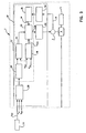
- FIG 2 which gives the block diagram of a steering assistance system of a motor vehicle, using an electropump according to the invention, it is found that the latter differs from the electropump known in the state of the technique, represented on the figure 1 by the fact that the pressure limiter is removed and that the function performed in the system known by the limiter is accomplished by means electronic pressure limiters which are part of the calculator / controller 13 'and are indicated by the shaded area 15 of the rack representing this calculator.
- the pump converts the speed of rotation of the electric motor 3 into hydraulic flow in the hydraulic circuit, namely the cylinder 4.
- the resisting torque exerted on the engine corresponds to the sum of the resistance torque due to the pressure in the hydraulic circuit and the resisting torque specific to the pump, the resisting torque linked to the motor can be considered negligible. Therefore, limiting the pressure in the hydraulic circuit is equivalent to limiting the torque provided by the engine. Thus, it has been found possible within the scope of the invention to obtain the limitation of the pressure in the hydraulic circuit by limiting the maximum current to be sent to the electric motor 2 for driving the pump 3.
- the maximum limiting current I LIM is determined according to three parameters, namely the supply voltage U BAT supplied by the battery, the temperature T MOS of the active electronic elements, namely transistors. used and the temperature T CA of the carrier board electronic components calculator.
- the values of the limit current I LIM vary according to these parameters and are taken in a calibration table made from tests.
- each group of three battery voltage and temperature values corresponds to a limit current value I LIM .
- This interdependence is represented on the figure 4 in 19a in the form of a three-dimensional diagram on the three axes of which are reported respectively the U BAT temperatures, T MOS active element temperatures and T ca card temperatures, next to the table of values.
- the system according to the invention further provides a torque management in avoidance, that is to say the system allows an exceeding of the limit current I LIM to have a better response of the system to avoid an obstacle by a quick maneuver.
- the avoidance current I EV is obtained from the limit current I LIM by multiplication according to a correction coefficient, as shown in the diagram.
- fig 4 box 19b representing on the ordinate axis the current I and on the abscissa axis the speed V, the vehicle speed V VEH .
- the computer 13 comprises a microprocessor 17 which is intended to establish by calculation the engine speed reference C RPM , that is to say the engine speed reference, from the vehicle speed V VEH and of the speed of rotation of the steering wheel V VO and, also by calculation, the limit current I LIM , from the vehicle speed V VEH and the values representative of the battery voltage U BAT and the temperature values T mos of the active elements of electronic devices and the temperature T ca of the card of this device.
- the calculation operations of the engine speed setpoint C RPM and the limit current I LIM are symbolized in the figure by boxes marked 18 and 19.
- the values of the battery voltage and of the temperature are applied to the inputs of a circuit of formatting 20 which adapts the level of these values to the level allowable for the microprocessor 17 which performs, before using them for calculating the current I LIM in 21 a software formatting 21.
- the microprocessor 17 calculates the motor control C M. This calculation is symbolized by box 22.
- the engine control C M is sent to the engine after having been shaped by a circuit 23 of the computer.
- the calculation of the motor control C M carried out by the microprocessor 17, again takes into account the current I M consumed by the motor, the value of which has been shaped by the circuit 24 of the computer and software formatted in FIG. by the microprocessor.
- the figure 4 shows in more detail the implementation of the operations just described.
- the result of the calculation engine speed calculation performed at 18 is subjected to a decision logic symbolized by the box 27, which is intended to let the setpoint C RPM for a servo operation of speed, materialized by block 28 or to prohibit this passage, according to a rotation authorization signal S AR of binary nature, which is the result of an assessment of the speed of rotation of the motor V RPM , provided for provide protection for the pump.
- a rotation authorization signal S AR of binary nature which is the result of an assessment of the speed of rotation of the motor V RPM , provided for provide protection for the pump.
- the speed control box 28 thus receives at an input a signal which is either the engine speed set point C RPM equal to zero, as a function of the rotation authorization signal S AR applied to box 27.
- the box speed control 28 receives at a second input a signal representative of the speed of rotation of the motor, noted V RPM and produces at its output a signal S PWM1 to ensure the nullity of the error between the two input signals , namely the setpoint C RPM and the speed signal V RPM .
- the signal is advantageously a pulse width modulated signal.
- the control is effected by applying the output signal S PWM1 to a first input of a bit comparator 31 which receives at a second input the calculated current value I LIM and a third input the information of the motor current I M. From the comparison operation results a signal S PWM2 , which is either identical to the signal S PWM1 or equal to zero, the signal is applied to a motor power control 32 applied to the motor 2.
- the control loop formed by the speed control unit 28, the comparator 31, the motor power control 32 and the motor 2 is designed to ensure that the motor rotation speed V RPM is slaved to the engine speed set point C RPM which has been calculated in 22.
- the comparator 31 passes the signal S PWM1 to the motor control 32.
- the comparator prohibits the passage of the signal S PWM1 , which has the consequence that the signal S PWM2 becomes zero and the power control of the motor decreases until the current I M consumed by the motor becomes lower than current I LIM . This situation causes the comparator to allow again the passage of the signal S PWM1 to the motor control 32.
- the invention provides a pump protection function in the case where the rotational speed of the motor 2 is too low to ensure proper operation of the pump.
- This protection function is illustrated by the diagram inside box 28 of the figure 4 represents the speed of rotation V RPM as a function of time t.
- V min the speed of rotation
- the engine is stopped after a time t1 and is then restarted after a time t2, the stopping and starting times t1 and t2 being fixed but configurable.
- the times t1 and t2 are modulated according to the accelerations and decelerations of the engine. In this case, the modulation laws of t1 and t2 are parameterizable.
- the protection function 30 of the pump applies to the decision logic 27 of the figure 4 , the aforementioned rotation authorization signal S AR , which is of a binary nature and causes the decision logic to allow the passage of the engine speed setpoint C RPM to the speed control box 28, as has been described above, this passage of the signal is forbidden.
- the figure 5 illustrates another version of implementation of the strategy of the system according to the invention, which consists in replacing the comparator 29 of the figure 4 by a scalar controller 34, the control 32 of the motor thus becoming a scalar control which limits the torque supplied to the motor 2 by controlling the value of the phase currents and by slaving the phase difference between the field created by the power supply Bri and that Ba created by the magnets at a constant value of ⁇ ⁇ / 2.
- This control is known in particular for synchronous machines in which the stator is generally provided with a three-phase winding, powered by a voltage and current system and creating in the gap a rotating induction field Bri.
- the Bri field tends to attract the rotor which is provided with permanent magnets producing an induction field Ba.
- the induction field tends to align, giving rise to an electromagnetic torque.
- the figure 6 shows another version of implementation of the invention which provides a vector control of the engine and uses instead of the scalar controller 34 of the figure 5 a vector controller 35.
- the vector control makes it possible to limit the torque supplied to the motor by directly controlling the current vector I s (t) .
- I s (t) the current vector
- all the information relating to the three currents of the three phases of the motor can be combined into a single mathematical quantity, namely the current phasor which is a spatial quantity.
- the advantage of using a spatial phaser rather than processing scalar magnitudes is that the three information pertaining to three phase currents of the motor are combined into one complex size.
- the phasor represented by the vector current I in the diagram given inside the vector controller box 35 can be decomposed, in a two-phase space system equivalent to a three-phase scalar system, according to a direct stator current component I D carried on the X-axis and a quadrature stator current component I Q carried on the ordinate axis.
- the advantage lies mainly in handling only two quantities.
- the invention is usable in all cases where an electric pump unit is used which is intended to provide hydraulic power while providing protection against possible overpressures in the hydraulic circuit, for example in braking systems and for suspension of a motor vehicle or forklift trucks or the like.
Claims (9)
- Elektropumpengruppe-System vom Typ, der einen Elektromotor, eine vom Elektromotor angetriebene Hydraulikpumpe, die dazu bestimmt ist, einer hydraulischen Vorrichtung eine hydraulische Leistung zur Verfügung zu stellen, und Mittel zur Begrenzung des Drucks des von der Pumpe in den Hydraulikkreis geleiteten Hyraulikfluids in Form von elektronischen Steuermitteln (13', 17, 15) ausgeführt sind, wobei die Druckbegrenzung durch Herstellen des maximalen Grenzstroms ILIM erfolgt, der an den Antriebsmotor (2) der Pumpe (3) zu leiten ist.
- System nach Anspruch 1 vom Typ, der einen Rechner zur Systembetriebssteuerung umfasst, dadurch gekennzeichnet, dass der Rechner (13') geeignet ist, um die vorgenannte elektronische Steuerung zu gewährleisten.
- System nach Anspruch 2, dadurch gekennzeichnet, dass der Rechner (13') Mittel zur Berechnung des maximalen Grenzstroms ILIM umfasst, der an den Antriebsmotor (2) der Pumpe (3) zu leiten ist.
- System nach Anspruch 3, dadurch gekennzeichnet, dass die Mittel zur Berechnung des maximalen Grenzstroms ILIM geeignet sind, eine Erhöhung des maximalen Grenzstroms durch Multiplikation mit einem vorbestimmten Vermeidungskoeffizienten, zum Beispiel eines Hindernisses beim Steuern des Fahrzeugs, zu gewährleisten.
- System nach Anspruch 4, dadurch gekennzeichnet, dass die elektronischen Mittel zur Druckbegrenzung geeignet sind, den Motorstrom IM mit dem vorgenannten maximalen Grenzstrom ILIM zu vergleichen und eine Kontrolle gewährleisten, die verhindert, dass der Motorstrom IM den Grenzstrom ILIM übersteigt.
- System nach Anspruch 5, dadurch gekennzeichnet, dass die elektronischen Steuermittel geeignet sind zu vermeiden, dass der Motor (2) niedrige Drehgeschwindigkeiten entwickelt, die einen unangepassten Betrieb der Pumpe (3) hervorrufen können.
- System nach einem der Ansprüche 1 bis 6, dadurch gekennzeichnet, dass es dazu bestimmt ist, ein Kraftfahrzeug auszustatten und diesem eine Lenkhilfe über eine Hydraulikzylindervorrichtung zur Verfügung zu stellen.
- System nach einem der Ansprüche 1 bis 6, dadurch gekennzeichnet, dass es eine Kalibriertafel umfasst, die auf Versuchen beruht und eine Zuordnung zwischen einer Gruppe von drei Batteriespannungs- und Temperaturwerten (UBAT, UMOS, TCA) und einem Grenzstromwert (ILIM) bestimmt, und dadurch, dass sich der Wert des maximalen Grenzstroms ILIM, der an den Motor zu schicken ist, aus der Kalibriertafel ergibt.
- System nach Anspruch 8, dadurch gekennzeichnet, dass die Gruppe der drei in die Kalibriertafel integrierten Werte jeweils ein Wert der Versorgungsspannung UBAT ist, der von der Batterie (UBAT) bereitgestellt wird, ein Temperaturwert der aktiven elektronischen Elemente (TMOS) und ein Temperaturwert der Karte (TCA), die die elektronischen Rechnerbauteile trägt.
Applications Claiming Priority (2)
| Application Number | Priority Date | Filing Date | Title |
|---|---|---|---|
| FR0405533A FR2870570B1 (fr) | 2004-05-21 | 2004-05-21 | Systeme de groupe electro-pompe pourvu de moyens de limitation de la pression du fluide hydraulique fourni par la pompe |
| FR0405533 | 2004-05-21 |
Publications (2)
| Publication Number | Publication Date |
|---|---|
| EP1598555A1 EP1598555A1 (de) | 2005-11-23 |
| EP1598555B1 true EP1598555B1 (de) | 2008-02-20 |
Family
ID=34942283
Family Applications (1)
| Application Number | Title | Priority Date | Filing Date |
|---|---|---|---|
| EP20050291034 Active EP1598555B1 (de) | 2004-05-21 | 2005-05-13 | Motor-Pumpeneinheit mit Mitteln zur Begrenzung des von der Pumpe erzeugten Hydraulikfluiddrucks |
Country Status (3)
| Country | Link |
|---|---|
| EP (1) | EP1598555B1 (de) |
| DE (1) | DE602005004829T2 (de) |
| FR (1) | FR2870570B1 (de) |
Cited By (1)
| Publication number | Priority date | Publication date | Assignee | Title |
|---|---|---|---|---|
| EP3789612A1 (de) | 2019-09-06 | 2021-03-10 | Weber-Hydraulik GmbH | Tragbares, akkubetriebenes hydraulikaggregat für hydraulische rettungswerkzeuge |
Families Citing this family (2)
| Publication number | Priority date | Publication date | Assignee | Title |
|---|---|---|---|---|
| JP5938901B2 (ja) * | 2011-12-28 | 2016-06-22 | 株式会社ジェイテクト | モータ制御装置および電動ポンプユニット |
| CN112401692B (zh) * | 2019-08-23 | 2023-04-14 | 广东美的生活电器制造有限公司 | 食物处理装置及其控制方法和控制系统、可读存储介质 |
Family Cites Families (5)
| Publication number | Priority date | Publication date | Assignee | Title |
|---|---|---|---|---|
| DE3819490A1 (de) * | 1988-06-08 | 1989-12-14 | Siemens Ag | Pumpsystem eines hydraulischen stellgliedes, z. b. fuer ein kfz |
| US5141402A (en) * | 1991-01-29 | 1992-08-25 | Vickers, Incorporated | Power transmission |
| JPH0544758U (ja) * | 1991-11-20 | 1993-06-15 | 光洋精工株式会社 | 電動ポンプ式パワーステアリング装置 |
| EP0718496A3 (de) * | 1994-12-19 | 1998-12-02 | Lockheed Martin Corporation | Elektrohydraulisches System mit variabler Unterstützung |
| AU5311496A (en) * | 1995-03-14 | 1996-10-02 | Boeing Company, The | Aircraft hydraulic pump control system |
-
2004
- 2004-05-21 FR FR0405533A patent/FR2870570B1/fr active Active
-
2005
- 2005-05-13 DE DE200560004829 patent/DE602005004829T2/de active Active
- 2005-05-13 EP EP20050291034 patent/EP1598555B1/de active Active
Cited By (1)
| Publication number | Priority date | Publication date | Assignee | Title |
|---|---|---|---|---|
| EP3789612A1 (de) | 2019-09-06 | 2021-03-10 | Weber-Hydraulik GmbH | Tragbares, akkubetriebenes hydraulikaggregat für hydraulische rettungswerkzeuge |
Also Published As
| Publication number | Publication date |
|---|---|
| FR2870570B1 (fr) | 2006-08-18 |
| DE602005004829D1 (de) | 2008-04-03 |
| FR2870570A1 (fr) | 2005-11-25 |
| EP1598555A1 (de) | 2005-11-23 |
| DE602005004829T2 (de) | 2009-03-12 |
Similar Documents
| Publication | Publication Date | Title |
|---|---|---|
| FR2851858A1 (fr) | Dispositif de controle de moteur synchrone et procede de correction de deviation en position rotationnelle du moteur synchrone | |
| FR2711601A1 (fr) | Dispositif de commande pour le système de direction assistée commandé par moteur d'un véhicule à moteur. | |
| EP0626287A1 (de) | Fahrzeug versehen mit einem elektrischen und mechanischem Bremssystem | |
| FR2840275A1 (fr) | Dispositif de detection d'anomalie de moteur et systeme de commande de direction a assistance electrique | |
| FR2843659A1 (fr) | Procede d'utilisation d'un dispositif d'observation de parametres en boucle ouverte pour la commande d'un moteur a aimant permanent | |
| FR2591957A1 (fr) | Appareillage de regulation de propulsion pour vehicules automobiles | |
| FR2890374A1 (fr) | Procede de gestion d'un actionneur de frein electromecanique notamment pour aeronef | |
| CA2196252A1 (fr) | Procede et dispositif de regulation commune de plusieurs moteurs electriques entrainant les roues motrices d'un vehicule automobile | |
| EP1598555B1 (de) | Motor-Pumpeneinheit mit Mitteln zur Begrenzung des von der Pumpe erzeugten Hydraulikfluiddrucks | |
| FR3016488A1 (fr) | Procede et dispositif de commande d'un levier de manœuvre d'un vehicule | |
| FR2824968A1 (fr) | Systeme de controle pour calculateur d'angle electrique | |
| FR2876194A1 (fr) | Procede de compensation d'un ecart d'angle de rotor d'un moteur et systeme de direction utilisant ce procede | |
| EP0812059B1 (de) | Regelverfahren für eine Drehmaschine, Einrichtung zur Durchführung des Verfahrens und Anwendung der Einrichtung bei einer Drehmaschine | |
| FR2959198B1 (fr) | Dispositif de direction assistee electrique | |
| EP1985828B1 (de) | Verfahren und Vorrichtung zur Betriebsregulierung eines Motors, der mit einer Drehmomentsteuerung ausgestattet ist | |
| FR2846486A1 (fr) | Dispositif de commande de fonctionnement pour moteur electrique et procede de commande de celui-ci | |
| WO2013156451A1 (fr) | Dispositif et procede de commande active d'un retour d'effort pour un organe de pilotage | |
| FR3064844A1 (fr) | Systeme de commande pour machine a induction et vehicule electrique | |
| FR2860481A1 (fr) | Dispositif de commande pour direction assistee a entrainement par moteur | |
| EP3217529B1 (de) | Verfahren und system zur steuerung eines elektromotors im falle eines ausfalls des positionssignals eines rotors | |
| EP1233506A9 (de) | Regelverfahren und Vorrichtung für eine rotierende elektrische Wechselstrommaschine, insbesondere Synchronmaschine | |
| EP4232332A1 (de) | Verfahren zur steuerung der seitlichen position eines fahrzeugs auf einer fahrspur | |
| FR3012270A1 (fr) | Procede et systeme de commande d'une machine electrique d'un vehicule automobile | |
| EP3437183B1 (de) | Vorrichtung zur regelung einer lichtmaschine eines kraftfahrzeugs und entsprechende lichtmaschine | |
| FR2749452A1 (fr) | Dispositif de commande de moteur electrique pour direction assistee |
Legal Events
| Date | Code | Title | Description |
|---|---|---|---|
| PUAI | Public reference made under article 153(3) epc to a published international application that has entered the european phase |
Free format text: ORIGINAL CODE: 0009012 |
|
| AK | Designated contracting states |
Kind code of ref document: A1 Designated state(s): AT BE BG CH CY CZ DE DK EE ES FI FR GB GR HU IE IS IT LI LT LU MC NL PL PT RO SE SI SK TR |
|
| AX | Request for extension of the european patent |
Extension state: AL BA HR LV MK YU |
|
| 17P | Request for examination filed |
Effective date: 20060330 |
|
| AKX | Designation fees paid |
Designated state(s): DE FR GB IT |
|
| 17Q | First examination report despatched |
Effective date: 20060526 |
|
| GRAP | Despatch of communication of intention to grant a patent |
Free format text: ORIGINAL CODE: EPIDOSNIGR1 |
|
| GRAS | Grant fee paid |
Free format text: ORIGINAL CODE: EPIDOSNIGR3 |
|
| GRAA | (expected) grant |
Free format text: ORIGINAL CODE: 0009210 |
|
| AK | Designated contracting states |
Kind code of ref document: B1 Designated state(s): DE FR GB IT |
|
| REG | Reference to a national code |
Ref country code: GB Ref legal event code: FG4D Free format text: NOT ENGLISH |
|
| REF | Corresponds to: |
Ref document number: 602005004829 Country of ref document: DE Date of ref document: 20080403 Kind code of ref document: P |
|
| PLBE | No opposition filed within time limit |
Free format text: ORIGINAL CODE: 0009261 |
|
| STAA | Information on the status of an ep patent application or granted ep patent |
Free format text: STATUS: NO OPPOSITION FILED WITHIN TIME LIMIT |
|
| 26N | No opposition filed |
Effective date: 20081121 |
|
| REG | Reference to a national code |
Ref country code: FR Ref legal event code: PLFP Year of fee payment: 12 |
|
| REG | Reference to a national code |
Ref country code: FR Ref legal event code: PLFP Year of fee payment: 13 |
|
| REG | Reference to a national code |
Ref country code: FR Ref legal event code: PLFP Year of fee payment: 14 |
|
| PGFP | Annual fee paid to national office [announced via postgrant information from national office to epo] |
Ref country code: IT Payment date: 20230529 Year of fee payment: 19 Ref country code: FR Payment date: 20230516 Year of fee payment: 19 Ref country code: DE Payment date: 20230525 Year of fee payment: 19 |
|
| PGFP | Annual fee paid to national office [announced via postgrant information from national office to epo] |
Ref country code: GB Payment date: 20230526 Year of fee payment: 19 |