EP1598503A1 - Construction safety assembly - Google Patents
Construction safety assembly Download PDFInfo
- Publication number
- EP1598503A1 EP1598503A1 EP04713912A EP04713912A EP1598503A1 EP 1598503 A1 EP1598503 A1 EP 1598503A1 EP 04713912 A EP04713912 A EP 04713912A EP 04713912 A EP04713912 A EP 04713912A EP 1598503 A1 EP1598503 A1 EP 1598503A1
- Authority
- EP
- European Patent Office
- Prior art keywords
- safety
- fencing
- aforementioned
- equipment
- post
- Prior art date
- Legal status (The legal status is an assumption and is not a legal conclusion. Google has not performed a legal analysis and makes no representation as to the accuracy of the status listed.)
- Withdrawn
Links
- 238000010276 construction Methods 0.000 title abstract description 5
- 230000007246 mechanism Effects 0.000 claims description 22
- 230000003014 reinforcing effect Effects 0.000 claims description 4
- 230000002452 interceptive effect Effects 0.000 claims 1
- 238000000034 method Methods 0.000 abstract 1
- XEEYBQQBJWHFJM-UHFFFAOYSA-N Iron Chemical compound [Fe] XEEYBQQBJWHFJM-UHFFFAOYSA-N 0.000 description 4
- 239000000463 material Substances 0.000 description 4
- 238000005034 decoration Methods 0.000 description 2
- 229910052742 iron Inorganic materials 0.000 description 2
- 239000002184 metal Substances 0.000 description 2
- 229910052751 metal Inorganic materials 0.000 description 2
- 238000009418 renovation Methods 0.000 description 2
- 238000009416 shuttering Methods 0.000 description 2
- 208000027418 Wounds and injury Diseases 0.000 description 1
- 238000004873 anchoring Methods 0.000 description 1
- 230000006835 compression Effects 0.000 description 1
- 238000007906 compression Methods 0.000 description 1
- 230000006378 damage Effects 0.000 description 1
- 238000010586 diagram Methods 0.000 description 1
- 238000001035 drying Methods 0.000 description 1
- 230000009977 dual effect Effects 0.000 description 1
- 230000000694 effects Effects 0.000 description 1
- 208000014674 injury Diseases 0.000 description 1
- 238000012423 maintenance Methods 0.000 description 1
- 239000004033 plastic Substances 0.000 description 1
- 206010042772 syncope Diseases 0.000 description 1
- 230000000007 visual effect Effects 0.000 description 1
Images


Classifications
-
- E—FIXED CONSTRUCTIONS
- E04—BUILDING
- E04G—SCAFFOLDING; FORMS; SHUTTERING; BUILDING IMPLEMENTS OR AIDS, OR THEIR USE; HANDLING BUILDING MATERIALS ON THE SITE; REPAIRING, BREAKING-UP OR OTHER WORK ON EXISTING BUILDINGS
- E04G21/00—Preparing, conveying, or working-up building materials or building elements in situ; Other devices or measures for constructional work
- E04G21/32—Safety or protective measures for persons during the construction of buildings
-
- E—FIXED CONSTRUCTIONS
- E04—BUILDING
- E04G—SCAFFOLDING; FORMS; SHUTTERING; BUILDING IMPLEMENTS OR AIDS, OR THEIR USE; HANDLING BUILDING MATERIALS ON THE SITE; REPAIRING, BREAKING-UP OR OTHER WORK ON EXISTING BUILDINGS
- E04G21/00—Preparing, conveying, or working-up building materials or building elements in situ; Other devices or measures for constructional work
- E04G21/32—Safety or protective measures for persons during the construction of buildings
- E04G21/3204—Safety or protective measures for persons during the construction of buildings against falling down
- E04G21/3223—Means supported by building floors or flat roofs, e.g. safety railings
- E04G21/3233—Means supported by building floors or flat roofs, e.g. safety railings without permanent provision in the floor or roof
-
- E—FIXED CONSTRUCTIONS
- E04—BUILDING
- E04G—SCAFFOLDING; FORMS; SHUTTERING; BUILDING IMPLEMENTS OR AIDS, OR THEIR USE; HANDLING BUILDING MATERIALS ON THE SITE; REPAIRING, BREAKING-UP OR OTHER WORK ON EXISTING BUILDINGS
- E04G25/00—Shores or struts; Chocks
- E04G25/04—Shores or struts; Chocks telescopic
- E04G25/06—Shores or struts; Chocks telescopic with parts held together by positive means
-
- E—FIXED CONSTRUCTIONS
- E04—BUILDING
- E04G—SCAFFOLDING; FORMS; SHUTTERING; BUILDING IMPLEMENTS OR AIDS, OR THEIR USE; HANDLING BUILDING MATERIALS ON THE SITE; REPAIRING, BREAKING-UP OR OTHER WORK ON EXISTING BUILDINGS
- E04G25/00—Shores or struts; Chocks
- E04G25/04—Shores or struts; Chocks telescopic
- E04G25/06—Shores or struts; Chocks telescopic with parts held together by positive means
- E04G25/061—Shores or struts; Chocks telescopic with parts held together by positive means by pins
-
- E—FIXED CONSTRUCTIONS
- E04—BUILDING
- E04G—SCAFFOLDING; FORMS; SHUTTERING; BUILDING IMPLEMENTS OR AIDS, OR THEIR USE; HANDLING BUILDING MATERIALS ON THE SITE; REPAIRING, BREAKING-UP OR OTHER WORK ON EXISTING BUILDINGS
- E04G25/00—Shores or struts; Chocks
- E04G25/04—Shores or struts; Chocks telescopic
- E04G25/06—Shores or struts; Chocks telescopic with parts held together by positive means
- E04G25/065—Shores or struts; Chocks telescopic with parts held together by positive means by a threaded nut
-
- E—FIXED CONSTRUCTIONS
- E04—BUILDING
- E04H—BUILDINGS OR LIKE STRUCTURES FOR PARTICULAR PURPOSES; SWIMMING OR SPLASH BATHS OR POOLS; MASTS; FENCING; TENTS OR CANOPIES, IN GENERAL
- E04H17/00—Fencing, e.g. fences, enclosures, corrals
- E04H17/14—Fences constructed of rigid elements, e.g. with additional wire fillings or with posts
- E04H17/16—Fences constructed of rigid elements, e.g. with additional wire fillings or with posts using prefabricated panel-like elements, e.g. wired frames
- E04H17/18—Corrals, i.e. easily transportable or demountable enclosures
-
- Y—GENERAL TAGGING OF NEW TECHNOLOGICAL DEVELOPMENTS; GENERAL TAGGING OF CROSS-SECTIONAL TECHNOLOGIES SPANNING OVER SEVERAL SECTIONS OF THE IPC; TECHNICAL SUBJECTS COVERED BY FORMER USPC CROSS-REFERENCE ART COLLECTIONS [XRACs] AND DIGESTS
- Y10—TECHNICAL SUBJECTS COVERED BY FORMER USPC
- Y10S—TECHNICAL SUBJECTS COVERED BY FORMER USPC CROSS-REFERENCE ART COLLECTIONS [XRACs] AND DIGESTS
- Y10S256/00—Fences
- Y10S256/06—Building construction guard rail
Definitions
- Wooden planks or iron bars which are normally available to cover the space between adjoining posts offer minimal safety on a building site and simply act as 'reassurance', that is to say visual symbols for the worker warning him that there is a danger present. These measures are insufficient to prevent accidents on a building site.
- this invention proposes safety equipment for building sites which has been specially designed to protect all workers on indoor and outdoor building sites.
- safety equipment it consists of safety equipment to be used on a building site subsequent to the shuttering stage, after the floor has set.
- the advantageous features of the safety equipment in this invention mean that it is also likely to be used for building being renovated as well as during interior decoration work.
- the safety equipment in the invention basically comprises of a series of safety posts built from telescopic tubular bodies equipped with supporting surfaces and locking mechanisms to prevent relative movement between the posts after they have placed in position.
- the layout of the telescopic tubes offers a wide range of heights. It must be remembered that these safety posts do not have the same function as the posts which are usually used on sites.
- the posts commonly used as supporting parts are specially designed to withstand axial compression loads. Posts are generally used to hold up construction work during maintenance or renovation work.
- safety posts in this invention are designed to support side impacts and not to avoid slide sideways when receiving impacts, vibrations and the possibility cracks in the construction work drying out.
- the upper end of the safety post has non-slip surfaces which in one example may be a rubber or similar material surface on the upper end of the safety post and a rough surface on the lower end or base which allows the safety post to be fixed on the building site.
- the lower end may be made into a foot with extensions going down to anchor the safety post on to the untreated surface of new building work for example.
- the side area on at least one of these pieces of equipment has the means to rapidly connect a fence using the transverse mechanism to join it to the safety posts.
- This fencing or rail offers the required safety to guarantee protection around the outside of the building site as well as providing access to interior stairways for instance, lift shafts and flat roofs.
- the layout of the banister as overall protection equipment prevents potentially fatal falls.
- the aforementioned banister as part of the safety equipment is designed to withstand weight and impact from the employees and building equipment present on the site.
- the aforementioned fencing comprises a horizontal bar structure and other reinforcing bars, in such a way that these bars may be extended in length to vary the operating length of the fencing.
- the invention may be equipped with an upper safety part which is especially adapted to connect a safety fence in such areas as a house's balcony or similar locations where there are no safety posts.
- This upper safety part comprises a vertical holding piece with the lower end having a horizontal extension ending in an inclined plane.
- the aforementioned upper holding piece on the safety equipment includes a horizontal part which moves vertically along it and is equipped with a locking mechanism.
- the configuration of this vertical holding piece lets a cornice or a protuberance on a building to be captured between the aforementioned horizontal extension and the moveable horizontal part as though it were a chuck. By doing this, the aforementioned inclined plane is properly supported on the upper end of the safety post. Therefore, the vertical holding piece remains fixed throughout the building work.
- the aforementioned inclined plane which is in the shape of a disc, may include a rubber safety base between it and the end of the safety post which it can rest on to prevent any of the parts from moving as happens with the aforementioned safety post.
- the vertical holding piece has rapid connection parts like the transversal fencing in accordance with the other parts of the invention. These connections allow fencing to be located in higher areas of the building work, above the safety posts, on balconies for example. Therefore the invention can become very simply constructed, highly effective dual safety equipment.
- the safety fencing includes a base or kick plate covering its lower section.
- the kick plate is designed to stop objects from falling onto people on the building site or to prevent an employee getting past it and removing the base to get inside the fencing. It is therefore, a part which reinforces the safety equipment's safety.
- the invention has locking equipment designed to prevent movement between the aforementioned telescopic tubes on the safety posts.
- the preferred configuration for this locking equipment will essentially include a tubular part which will fit tightly around the central part of the safety post where it holds together both tubes.
- This tubular part is threaded on the inside to be able to fit an outer thread on the upper end of the lower tube. In this way turning the tubular part to tighten it moves it vertically toward the upper tube to butt up against a rod located in its opening to prevent the safety post tubes from moving.
- this tubular part has at least one side opening to house a lever key which has been designed to rotate it.
- the rapid connection devices on the aforementioned fencing are made from hooks designed to be located in the openings on the fencing.
- these rapid fencing connection devices are pairs of hooks on the side of each safety post tube which are designed to be put into the respective pairs of holes on the fences forming them into a right angle.
- each hook in the pairs of hooks is welded to the safety post at different heights to prevent interference between the aforementioned fencing.
- the rapid fencing connection devices on the invention are on every tube on each safety post so that the safety post may connect fencing at different heights. This guarantees safety on the building site in any situation and for any type of work being carried out.
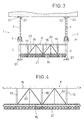
- Safety equipment comprising a series of vertical safety posts will be described. These safety posts (1) will be separated as illustrated in figure 3 attached to this report.
- This diagram shows two of the aforementioned posts (1).
- the safety posts (1) in the safety equipment in the invention is painted in a striking colour so that it can be easily detected in a danger zone by the operator, for example, fluorescent orange.
- Each safety post (1) shown basically comprises of a lower tube (2) and upper tube (3) which is held in position by sliding it inside the lower tube (2) telescopically in order to obtain different heights. In the middle area there are mechanisms (4) to prevent movement between the tubes (2, 3). These mechanisms are described in more detail below.
- These safety posts (1) have mechanisms (5) for the rapid connection of a fence (6) in a transversal position in terms of each safety post (1).
- the fence (6) is up to 3 metres long and its configuration may be clearly seen in figure 4 of the drawings.
- the rapid fencing connection mechanisms (5) are made up of hooks (in the example shown). These hooks may be anywhere along the lower tube (2) and on the upper tube (3) (or on both) depending on the degree of coverage required by the building site.
- the fencing (6) covers the existing gap between two adjoining safety posts (1) to great effect. This provides the required safety to guarantee protection around the outside of the building site, stairways, lift shafts and other locations on the building site.
- the configuration of the fencing (6) shall be described in greater detail in terms of figure 4 of the drawings.
- a significant feature of the invention and referring to figure 5 of the drawings is the upper end (22) and lower end (23) of the safety posts (1) in the invention. These are equipped with the relevant non-slip surfaces (24).
- the lower part of the lower tube (2) on the safety post (1) has a metal foot grip or a grooved or rough shoe extending downwards to improve the anchoring of the safety post (1) onto the ground of the building site. More specifically the upper end (22) of the safety post (1) may have a grooved rubber base (24) while the lower end (23) of the safety post (1) may have a grooved rubber foot with thick studs (24).
- This configuration makes the invention safer because each safety post (1) can effectively absorb blows and vibrations, preventing the posts (1) from sliding sideways on impact and also absorbing possible cracks when the building work dries out.
- the invented piece of equipment also has the option of an upper safety piece, called (7) in drawing number 1.
- the upper safety piece (7) comprises a vertical holding piece (8) at the lower of which is a horizontal extension (9) ending in an inclined plane disc (10).
- the upper holding piece also has a horizontally moveable piece (11) and is equipped with mechanisms (12) to lock this part in a horizontal position (11) with regard to this vertical holding piece (8).
- the aforementioned upper holding piece (7) allows the external section of a building's cornice or protuberance (13) to be trapped between the aforementioned horizontal extension (9) and the moveable horizontal piece (11).
- the assembled position shown demonstrates that the lower surface of the inclined plane disc (10) is supported on the upper end of the safety post (1) so that the vertical holding piece (7) remains fixed during the building work due to the locking mechanisms (12) which, by way of an example may be a screw, (although other equivalent locking mechanisms are possible).
- the disc (10) includes a rubber safety base (14) assembled between the disc itself (10) on the horizontal extension (9) and the upper end of the tube (3) on the safety post (1) This prevents the relative movement and vibration of the different parts.
- the upper holding piece (7) also has traversal fencing (6) rapid connection mechanisms (5). This allows fencing (6) to be located in upper areas of the building work above safety posts (1) as seen in figure 1.
- Figures 3 and 4 shows that the traversal fencing (6) with the safety equipment has a relatively lightweight structure comprising horizontal bars (17, 18, 19) and reinforcing bars (20).
- the fencing might have to be adapted to different gaps between the safety posts (1) although this is not illustrated.
- the fencing structure may be extended lengthways to change its operating length.
- This scenario allows this safety equipment invention to be used on renovation and interior decoration work.
- the equipment may be effectively used for repairing balcony ceilings, attaching awnings and changing balustrades, etc., where the safety equipment on the upper section of the balcony covers the gap where an employee working above the height of the balcony fencing may fall.
- the base (21) On the lower part of the aforementioned fencing (6) there is a base or foot (21) which covers the lower part of the fencing (6) to prevent objects falling off which may accidentally injure an employee.
- the base (21) may be a strip of canvas stretched between the end upright bars on the fencing (6). This may also be a metal or plastic plate or any other type of suitably strong material.
- the base (21) may also be made from a combination of materials, for example, an area of canvas plus a lower band of another suitably rigid material.
- the invention also has locking mechanisms (4) on the safety posts (1) which prevent the backward movement of the tubular parts (2, 3).
- Figures 2 and 5 show that these mechanisms (4) include a tight fitting tubular piece (25) which surrounds the central part of the safety post (1) where the two tubes fit together (2, 3) as seen in figure 5.
- the tube is threaded on the inside (25) in order for an outer thread (26) on the upper end of the lower tube (2) to be screwed onto it as shown in figure 2.
- Turning the tube (25) in the tightening direction moves it vertically towards the upper tube (3) butting up against a rod (27) (or hiding a locking pin) which is housed in the opening (28) to prevent the aforementioned tubes (2, 3) on the safety posts from moving.
- the rod (27) is locked by the safety locking part (27a) to prevent it from accidentally falling out of the safety post (1)
- the tube (25) has a pair of side openings (29, 30) where the special lever keys (31) are placed.
- This (31) key is designed to turn the tube (25)and is to be stored in a container (not shown) on each floor of the building. After the key (31) has been used, the operator returns it to the aforemention container so that everyone is aware of the importance of safety on a building site.
Landscapes
- Engineering & Computer Science (AREA)
- Architecture (AREA)
- Civil Engineering (AREA)
- Structural Engineering (AREA)
- Mechanical Engineering (AREA)
- Emergency Lowering Means (AREA)
- Mutual Connection Of Rods And Tubes (AREA)
- Refuge Islands, Traffic Blockers, Or Guard Fence (AREA)
- Fencing (AREA)
Abstract
This is formed by safety posts with non slip ends
which are equipped with rapid connection parts for fencing
and with the option of an upper safety part in the form of
a jack with a lower, horizontal, inclined extension to be
attached to a building's cornice or protuberance which may
also include these fencing connection methods. They may be
extended in length and include a base which covers the
lower part of the same.
It's very simple construction means that it is
possible to guarantee the overall protection of workers on
outdoor and indoor building sites, preventing accidents
with the invention's safety equipment.
Description
This application for an Invention Patent
consists of, "SAFETY EQUIPMENT FOR BUILDING SITES" as
stated in the title which has been constructed, set out and
designed to fulfil the purpose for which it has
specifically been designed, with a maximum degree of safety
and effectiveness and providing numerous advantages as
shown in this document.
The high rate of accidents in the building
industry arising from the high degree of risk in the work
carried out (by its very nature and by the nature of the
site where it is carried out) is currently a very serious
problem. Accidental falls on building sites, particularly
falls from a great height, plus being hit by objects, are
currently the main risks to workers on a building site.
Awareness about the high degree of risk in the
construction industry has been increasing over recent
years. A significant degree of effort has been put into
protection equipment such as nets and other similar
equipment in order to prevent injury. Also access to the
building site has to be maintained in a good condition,
there have been improvements and increases in signage as
well as showing precautions to be taken on the building
site. Nevertheless, these safety measures are unfortunately
still insufficient to reduce the site accident rates in the
industry.
On building sites which use posts before and/or
after shuttering the building, after the floors have set,
the risk of the worker falling, (perhaps through tripping
accidentally on the floor, through, for example, becoming
unbalanced after straining too hard, or through fainting,
etc) is very high because of the gaps between posts,
particularly when this space opens out onto a long drop,
creating a significant potential risk. Usually this gap is
partially covered with wooden planks, iron bars, nets or it
is left without being covered. This is not a solution to
the problem at all.
Therefore there is potentially serious danger for
builders on a building site because of these gaps between
posts. Wooden planks or iron bars which are normally
available to cover the space between adjoining posts offer
minimal safety on a building site and simply act as
'reassurance', that is to say visual symbols for the worker
warning him that there is a danger present. These measures
are insufficient to prevent accidents on a building site.
To solve this problem this invention proposes
safety equipment for building sites which has been
specially designed to protect all workers on indoor and
outdoor building sites.
It consists of safety equipment to be used on a
building site subsequent to the shuttering stage, after the
floor has set. As will be shown later, the advantageous
features of the safety equipment in this invention mean
that it is also likely to be used for building being
renovated as well as during interior decoration work.
The safety equipment in the invention basically
comprises of a series of safety posts built from telescopic
tubular bodies equipped with supporting surfaces and
locking mechanisms to prevent relative movement between the
posts after they have placed in position. The layout of the
telescopic tubes offers a wide range of heights. It must be
remembered that these safety posts do not have the same
function as the posts which are usually used on sites. The
posts commonly used as supporting parts are specially
designed to withstand axial compression loads. Posts are
generally used to hold up construction work during
maintenance or renovation work. However, safety posts in
this invention are designed to support side impacts and not
to avoid slide sideways when receiving impacts, vibrations
and the possibility cracks in the construction work drying
out. Therefore, according to the invention, the upper end
of the safety post has non-slip surfaces which in one
example may be a rubber or similar material surface on the
upper end of the safety post and a rough surface on the
lower end or base which allows the safety post to be fixed
on the building site. The lower end may be made into a foot
with extensions going down to anchor the safety post on to
the untreated surface of new building work for example.
On the other hand, the side area on at least one
of these pieces of equipment has the means to rapidly
connect a fence using the transverse mechanism to join it
to the safety posts. This fencing or rail offers the
required safety to guarantee protection around the outside
of the building site as well as providing access to
interior stairways for instance, lift shafts and flat
roofs. The layout of the banister as overall protection
equipment prevents potentially fatal falls. In order to
achieve this, the aforementioned banister as part of the
safety equipment is designed to withstand weight and impact
from the employees and building equipment present on the
site.
In some scenarios it may be necessary to adapt
the fencing to different gaps between safety posts. To do
this and in accordance with the invention's safety
features, the aforementioned fencing comprises a horizontal
bar structure and other reinforcing bars, in such a way
that these bars may be extended in length to vary the
operating length of the fencing.
As an option, the invention may be equipped with
an upper safety part which is especially adapted to connect
a safety fence in such areas as a house's balcony or
similar locations where there are no safety posts. This
upper safety part comprises a vertical holding piece with
the lower end having a horizontal extension ending in an
inclined plane. The aforementioned upper holding piece on
the safety equipment includes a horizontal part which moves
vertically along it and is equipped with a locking
mechanism. The configuration of this vertical holding piece
lets a cornice or a protuberance on a building to be
captured between the aforementioned horizontal extension
and the moveable horizontal part as though it were a chuck.
By doing this, the aforementioned inclined plane is
properly supported on the upper end of the safety post.
Therefore, the vertical holding piece remains fixed
throughout the building work. The aforementioned inclined
plane, which is in the shape of a disc, may include a
rubber safety base between it and the end of the safety
post which it can rest on to prevent any of the parts from
moving as happens with the aforementioned safety post. The
vertical holding piece has rapid connection parts like the
transversal fencing in accordance with the other parts of
the invention. These connections allow fencing to be
located in higher areas of the building work, above the
safety posts, on balconies for example. Therefore the
invention can become very simply constructed, highly
effective dual safety equipment.
The way the equipment has been invented means
that the safety fencing includes a base or kick plate
covering its lower section. The kick plate is designed to
stop objects from falling onto people on the building site
or to prevent an employee getting past it and removing the
base to get inside the fencing. It is therefore, a part
which reinforces the safety equipment's safety.
As previously stated, the invention has locking
equipment designed to prevent movement between the
aforementioned telescopic tubes on the safety posts. The
preferred configuration for this locking equipment will
essentially include a tubular part which will fit tightly
around the central part of the safety post where it holds
together both tubes. This tubular part is threaded on the
inside to be able to fit an outer thread on the upper end
of the lower tube. In this way turning the tubular part to
tighten it moves it vertically toward the upper tube to
butt up against a rod located in its opening to prevent the
safety post tubes from moving.
Preferably, this tubular part has at least one
side opening to house a lever key which has been designed
to rotate it. This is a special key which is located inside
a container on each floor of the building. This container
will be a striking colour so that it can be found easily
and therefore may be used on the safety post. Once the key
has been used, the operator must return it to the
container. This obliges the employee to be aware of the
importance of safety on the building site.
In order to simplify the equipment and to make it
easy to assemble, the rapid connection devices on the
aforementioned fencing are made from hooks designed to be
located in the openings on the fencing. A specific example
of this would mean that these rapid fencing connection
devices are pairs of hooks on the side of each safety post
tube which are designed to be put into the respective pairs
of holes on the fences forming them into a right angle.
Here, each hook in the pairs of hooks is welded to the
safety post at different heights to prevent interference
between the aforementioned fencing.
The rapid fencing connection devices on the
invention are on every tube on each safety post so that the
safety post may connect fencing at different heights. This
guarantees safety on the building site in any situation and
for any type of work being carried out.
The features and advantages of the safety
equipment in this invention will be evident from the
detailed description of its preferred configuration shown
below. This is a non-limiting example and includes the
attached drawings:
The parts used in the preferred configuration of
the invention are described below:
Safety equipment comprising a series of vertical
safety posts will be described. These safety posts (1) will
be separated as illustrated in figure 3 attached to this
report. This diagram shows two of the aforementioned posts
(1). The safety posts (1) in the safety equipment in the
invention is painted in a striking colour so that it can be
easily detected in a danger zone by the operator, for
example, fluorescent orange. Each safety post (1) shown
basically comprises of a lower tube (2) and upper tube (3)
which is held in position by sliding it inside the lower
tube (2) telescopically in order to obtain different
heights. In the middle area there are mechanisms (4) to
prevent movement between the tubes (2, 3). These mechanisms
are described in more detail below.
These safety posts (1) have mechanisms (5) for
the rapid connection of a fence (6) in a transversal
position in terms of each safety post (1). In the example,
the fence (6) is up to 3 metres long and its configuration
may be clearly seen in figure 4 of the drawings. As these
drawings show that the rapid fencing connection mechanisms
(5) are made up of hooks (in the example shown). These
hooks may be anywhere along the lower tube (2) and on the
upper tube (3) (or on both) depending on the degree of
coverage required by the building site. In every situation
the fencing (6) covers the existing gap between two
adjoining safety posts (1) to great effect. This provides
the required safety to guarantee protection around the
outside of the building site, stairways, lift shafts and
other locations on the building site. The configuration of
the fencing (6) shall be described in greater detail in
terms of figure 4 of the drawings.
A significant feature of the invention and
referring to figure 5 of the drawings is the upper end (22)
and lower end (23) of the safety posts (1) in the
invention. These are equipped with the relevant non-slip
surfaces (24). The lower part of the lower tube (2) on the
safety post (1) has a metal foot grip or a grooved or rough
shoe extending downwards to improve the anchoring of the
safety post (1) onto the ground of the building site. More
specifically the upper end (22) of the safety post (1) may
have a grooved rubber base (24) while the lower end (23) of
the safety post (1) may have a grooved rubber foot with
thick studs (24). This configuration makes the invention
safer because each safety post (1) can effectively absorb
blows and vibrations, preventing the posts (1) from sliding
sideways on impact and also absorbing possible cracks when
the building work dries out.
With particular to figure 1 in the drawings, the
invented piece of equipment also has the option of an upper
safety piece, called (7) in drawing number 1. The upper
safety piece (7) comprises a vertical holding piece (8) at
the lower of which is a horizontal extension (9) ending in
an inclined plane disc (10). The upper holding piece also
has a horizontally moveable piece (11) and is equipped with
mechanisms (12) to lock this part in a horizontal position
(11) with regard to this vertical holding piece (8). As
figure 1 in the drawings attached to this report shows, the
aforementioned upper holding piece (7) allows the external
section of a building's cornice or protuberance (13) to be
trapped between the aforementioned horizontal extension (9)
and the moveable horizontal piece (11). The assembled
position shown demonstrates that the lower surface of the
inclined plane disc (10) is supported on the upper end of
the safety post (1) so that the vertical holding piece (7)
remains fixed during the building work due to the locking
mechanisms (12) which, by way of an example may be a screw,
(although other equivalent locking mechanisms are
possible). The disc (10) includes a rubber safety base (14)
assembled between the disc itself (10) on the horizontal
extension (9) and the upper end of the tube (3) on the
safety post (1) This prevents the relative movement and
vibration of the different parts.
As with the upper and lower tubes (3, 2) on the
safety post (1), the upper holding piece (7) also has
traversal fencing (6) rapid connection mechanisms (5). This
allows fencing (6) to be located in upper areas of the
building work above safety posts (1) as seen in figure 1.
Figures 3 and 4 shows that the traversal fencing
(6) with the safety equipment has a relatively lightweight
structure comprising horizontal bars (17, 18, 19) and
reinforcing bars (20). Sometimes the fencing might have to
be adapted to different gaps between the safety posts (1)
although this is not illustrated. In order for it to be
able to do this, it is envisaged that the fencing structure
may be extended lengthways to change its operating length.
This scenario allows this safety equipment invention to be
used on renovation and interior decoration work. By way of
an example, the equipment may be effectively used for
repairing balcony ceilings, attaching awnings and changing
balustrades, etc., where the safety equipment on the upper
section of the balcony covers the gap where an employee
working above the height of the balcony fencing may fall.
On the lower part of the aforementioned fencing
(6) there is a base or foot (21) which covers the lower
part of the fencing (6) to prevent objects falling off
which may accidentally injure an employee. The base (21)
may be a strip of canvas stretched between the end upright
bars on the fencing (6). This may also be a metal or
plastic plate or any other type of suitably strong
material. The base (21) may also be made from a combination
of materials, for example, an area of canvas plus a lower
band of another suitably rigid material.
As previously stated, the invention also has
locking mechanisms (4) on the safety posts (1) which
prevent the backward movement of the tubular parts (2, 3).
Figures 2 and 5 show that these mechanisms (4) include a
tight fitting tubular piece (25) which surrounds the
central part of the safety post (1) where the two tubes fit
together (2, 3) as seen in figure 5. The tube is threaded
on the inside (25) in order for an outer thread (26) on the
upper end of the lower tube (2) to be screwed onto it as
shown in figure 2. Turning the tube (25) in the tightening
direction moves it vertically towards the upper tube (3)
butting up against a rod (27) (or hiding a locking pin)
which is housed in the opening (28) to prevent the
aforementioned tubes (2, 3) on the safety posts from
moving. The rod (27) is locked by the safety locking part
(27a) to prevent it from accidentally falling out of the
safety post (1)
As can be seen in figure 2, the tube (25) has a
pair of side openings (29, 30) where the special lever keys
(31) are placed. This (31) key is designed to turn the tube
(25)and is to be stored in a container (not shown) on each
floor of the building. After the key (31) has been used,
the operator returns it to the aforemention container so
that everyone is aware of the importance of safety on a
building site.
Having sufficiently described the details of the
safety equipment in this invention using the attached
drawings, it is understood that appropriate changes to the
details of the invention may be made, whenever the
essential features of the summarised invention are not
altered.
Claims (7)
- "SAFETY EQUIPMENT FOR BUILDING SITES ", this safety equipment includes several safety posts (1) each comprising at least two telescopic tubes (2, 3) equipped with locking mechanisms (4) to prevent the posts (1) from moving. The safety posts (1) are characterised on the side by hooks for locating in openings in fencing (6) comprising a structure of horizontal bars (15, 16) and reinforcing bars (20) on each part.
- "SAFETY EQUIPMENT FOR BUILDING SITES" according to the lst claim, characterised by the fact that it includes an upper safety piece (7) comprising a vertical holding piece (8) whose lower end has a horizontal extension (9) ending in an inclined plane (10). This upper safety piece (7) includes a vertically moveable horizontal piece and locking equipment (12) for it. This upper safety piece (7) is designed to trap a building's cornice or protuberance (13) between the aforementioned horizontal extension (9) and the moveable horizontal piece (11) using the aforementioned inclined plane (10) supported on the upper end of the safety post (1).
- "SAFETY EQUIPMENT FOR BUILDING SITES" according to the 2nd claim, characterised by the fact that the upper safety piece (7) is equipped with hooks for the rapid connection (5) of transversal fencing (6).
- "SAFETY EQUIPMENT FOR BUILDING SITES" according to the 1st claim, characterised by the fact that the aforementioned locking mechanisms {4) prevent movement of the telescopic tubes (2, 3) on the safety post (1) including a tight fitting tubular part (25) surrounding the central part of the safety post (1) where the tubes join (2, 3) which is threaded on the inside to join with the outside thread (26) on the upper part of the lower tube (2), so that when the tight fitting tube is turned (25) to tighten it, there is a vertical movement towards the upper tube (3) on the safety post (1) until it butts up against a rod (27) and which this tube (25) has a side opening (29, 30) to locate a lever key (31) which turns the tube.
- "SAFETY EQUIPMENT FOR BUILDING SITES" according to the 1st claim, characterised by the fact that the aforementioned hooks are in pairs on the safety post (1) to be placed into the openings on the respective pairs of fencing (6) forming a right angle between them. Each hook in these pairs is at a different height to prevent it from interfering with the aforementioned fencing (6).
- "SAFETY EQUIPMENT FOR BUILDING SITES" according to the 1st claim, characterised by the fact that the aforementioned bars (15, 16) are extendible in length to vary the operating length of the fencing (6).
- "SAFETY EQUIPMENT FOR BUILDING SITES" according to the 1st and 4th claim, characterised by the fact that the aforementioned locking mechanism (4) preventing the movement of the telescopic tubes (2, 3) on the safety post (1) include a safety flange to lock the closure of the telescopic tubes (2, 3).
Applications Claiming Priority (3)
| Application Number | Priority Date | Filing Date | Title |
|---|---|---|---|
| ES200300462 | 2003-02-26 | ||
| ES200300462A ES2214143B1 (en) | 2003-02-26 | 2003-02-26 | SAFETY ASSEMBLY FOR WORKS. |
| PCT/ES2004/000080 WO2004076777A1 (en) | 2003-02-26 | 2004-02-24 | Construction safety assembly |
Publications (1)
| Publication Number | Publication Date |
|---|---|
| EP1598503A1 true EP1598503A1 (en) | 2005-11-23 |
Family
ID=32921760
Family Applications (1)
| Application Number | Title | Priority Date | Filing Date |
|---|---|---|---|
| EP04713912A Withdrawn EP1598503A1 (en) | 2003-02-26 | 2004-02-24 | Construction safety assembly |
Country Status (5)
| Country | Link |
|---|---|
| US (1) | US7273200B2 (en) |
| EP (1) | EP1598503A1 (en) |
| AU (1) | AU2004215193B2 (en) |
| ES (2) | ES2214143B1 (en) |
| WO (1) | WO2004076777A1 (en) |
Cited By (4)
| Publication number | Priority date | Publication date | Assignee | Title |
|---|---|---|---|---|
| EP2000613A1 (en) * | 2007-06-07 | 2008-12-10 | Gélase M. Havyarimana | Device for protecting an opening |
| EP2243899A2 (en) | 2009-04-17 | 2010-10-27 | Antonio Puzzonia | Safety post for making fencings in construction sites |
| EP1921226A3 (en) * | 2006-11-01 | 2012-06-27 | Brine, David Michael | Support device |
| CN106409135A (en) * | 2016-12-07 | 2017-02-15 | 国网山东省电力公司烟台供电公司 | Electric transmission line warning sign hanging device |
Families Citing this family (14)
| Publication number | Priority date | Publication date | Assignee | Title |
|---|---|---|---|---|
| US20050204673A1 (en) * | 2004-03-04 | 2005-09-22 | Reed William E | Wall repair system and method |
| CA2857657A1 (en) * | 2004-07-28 | 2006-01-28 | Jonathon Jonny Melic | Guard rail safety system |
| US7255312B2 (en) | 2004-07-29 | 2007-08-14 | Jonny J Melic | Guard rail safety system |
| ES2278480B1 (en) * | 2004-10-14 | 2008-05-16 | Daniel Granados Sanchez | ANTICAID SECURITY SYSTEM. |
| WO2006042889A2 (en) * | 2004-10-14 | 2006-04-27 | Granados Sanchez Daniel | Fall-prevention safety system |
| ES2270686B1 (en) * | 2005-01-17 | 2008-01-01 | Sistemas Tecnicos De Encofrados, S.A. | CLAMP FOR PROTECTION RAILINGS IN WORKS. |
| CA2515750C (en) * | 2005-08-10 | 2014-06-03 | Jonathan Jonny Melic | Locking and lifting mechanism for safety fence support post |
| US7584932B2 (en) * | 2007-10-23 | 2009-09-08 | Lung Ching Shih | Construction prop |
| US9784001B1 (en) * | 2011-05-03 | 2017-10-10 | Paul Kristen, Inc | Adjustable scaffolding suspension assembly |
| JP6611637B2 (en) * | 2016-03-01 | 2019-11-27 | 三菱電機ビルテクノサービス株式会社 | Roll type safety fence |
| GB2587118B (en) * | 2018-01-19 | 2023-05-10 | Jonny Melic Jonathan | Safety net and safety net components for multi-storey building construction |
| WO2020107062A1 (en) * | 2018-11-29 | 2020-06-04 | John Arthur Grey | A support frame and method of use |
| CN111778898B (en) * | 2020-06-24 | 2021-09-17 | 浙江常青公路工程有限公司 | Mountain region highway rail guard of dish |
| CN114412214B (en) * | 2022-01-28 | 2023-09-01 | 中国建筑第二工程局有限公司 | Anti-falling mechanism of operation platform for building construction |
Family Cites Families (18)
| Publication number | Priority date | Publication date | Assignee | Title |
|---|---|---|---|---|
| US3335987A (en) * | 1966-08-01 | 1967-08-15 | Moore Corp Lee C | Adjustable oil well mast support |
| US3439898A (en) * | 1968-01-29 | 1969-04-22 | Gen Safety Inc | Safety barrier and barrier fence |
| CA917972A (en) * | 1968-11-30 | 1973-01-02 | E. Dickey Edward | Safety fence support column |
| US3662993A (en) * | 1971-04-07 | 1972-05-16 | Anthony Lionetto | Protective guard fixture |
| US3734467A (en) * | 1971-05-19 | 1973-05-22 | Anthes Equip Ltd | Wire wall partition |
| US3822850A (en) * | 1973-01-29 | 1974-07-09 | Dell Holdings Ltd | Support for construction fence |
| CA996385A (en) * | 1973-05-14 | 1976-09-07 | Dominion Bridge Company Limited | Telescoping post |
| US4576354A (en) * | 1984-06-14 | 1986-03-18 | Blessing Sr William R | Panel overhead support apparatus |
| US4688686A (en) * | 1986-04-02 | 1987-08-25 | Rev-A-Shelf, Inc. | Vertically adjustable rotary shelf assembly |
| US5031724A (en) * | 1989-12-29 | 1991-07-16 | James E. Wright | Shoring frame pillar |
| US5297779B1 (en) * | 1993-01-13 | 1997-04-15 | Sumner Manufacturing Co Inc | Jack mechanism having safety protection for workers |
| ES2128915B1 (en) * | 1996-01-04 | 2000-02-01 | Polo Vicente Herrero | PROTECTION SYSTEM ON THE EDGE OF SLABS. |
| US5826847A (en) * | 1997-06-30 | 1998-10-27 | Warner; Stanley H. | Telescoping pole with quick length adjustment |
| US6467741B1 (en) * | 2001-03-30 | 2002-10-22 | Lung Ching Shih | Steel prop capable of bearing bidirectional applied force |
| ES1048780Y (en) * | 2001-04-11 | 2002-02-01 | Ruano Salvador Villanueva | SECURITY RAIL WITH EXTENSION ELEMENTS |
| ES1048984Y (en) * | 2001-05-16 | 2002-06-01 | Diaz Anastasio Cuenca | PERFECTED SUPPORT FOR THE INSTALLATION OF PROTECTIVE RAILINGS ON CONSTRUCTION AND SIMILAR BUILDINGS. |
| CA2418165A1 (en) * | 2003-01-31 | 2004-07-31 | Paul Gillespie, D/B/A/ Gillespie Practical Technologies Company | Adjustable shoring post |
| US7255312B2 (en) * | 2004-07-29 | 2007-08-14 | Jonny J Melic | Guard rail safety system |
-
2003
- 2003-02-26 ES ES200300462A patent/ES2214143B1/en not_active Expired - Fee Related
-
2004
- 2004-02-24 US US10/547,016 patent/US7273200B2/en not_active Expired - Fee Related
- 2004-02-24 WO PCT/ES2004/000080 patent/WO2004076777A1/en not_active Ceased
- 2004-02-24 AU AU2004215193A patent/AU2004215193B2/en not_active Expired - Fee Related
- 2004-02-24 EP EP04713912A patent/EP1598503A1/en not_active Withdrawn
-
2005
- 2005-11-29 ES ES200502943A patent/ES2288790B1/en not_active Expired - Fee Related
Non-Patent Citations (1)
| Title |
|---|
| See references of WO2004076777A1 * |
Cited By (5)
| Publication number | Priority date | Publication date | Assignee | Title |
|---|---|---|---|---|
| EP1921226A3 (en) * | 2006-11-01 | 2012-06-27 | Brine, David Michael | Support device |
| EP2000613A1 (en) * | 2007-06-07 | 2008-12-10 | Gélase M. Havyarimana | Device for protecting an opening |
| FR2917110A1 (en) * | 2007-06-07 | 2008-12-12 | Gen Materiel De Batiments Trav | DEVICE FOR PROTECTING AN OPENING |
| EP2243899A2 (en) | 2009-04-17 | 2010-10-27 | Antonio Puzzonia | Safety post for making fencings in construction sites |
| CN106409135A (en) * | 2016-12-07 | 2017-02-15 | 国网山东省电力公司烟台供电公司 | Electric transmission line warning sign hanging device |
Also Published As
| Publication number | Publication date |
|---|---|
| US20060108176A1 (en) | 2006-05-25 |
| WO2004076777A1 (en) | 2004-09-10 |
| ES2214143B1 (en) | 2005-11-01 |
| ES2214143A1 (en) | 2004-09-01 |
| US7273200B2 (en) | 2007-09-25 |
| AU2004215193B2 (en) | 2008-12-04 |
| ES2288790B1 (en) | 2008-10-16 |
| ES2288790A1 (en) | 2008-01-16 |
| AU2004215193A1 (en) | 2004-09-10 |
Similar Documents
| Publication | Publication Date | Title |
|---|---|---|
| AU2004215193B2 (en) | Construction safety assembly | |
| US7699276B2 (en) | Support post with surface-engaging members | |
| CA2803836C (en) | Guard rail safety system | |
| US5842685A (en) | Temporary guard rail system | |
| USRE39842E1 (en) | Temporary guard rail system | |
| US3589682A (en) | Safety fence support column | |
| US3662993A (en) | Protective guard fixture | |
| US6840350B2 (en) | Adjustable scaffold and walkboard ladder holder | |
| CN108699848A (en) | Safety fence system | |
| US20070246299A1 (en) | Safety barrier stanchion | |
| US20120186066A1 (en) | Ladder access system and method for using same | |
| RU2400609C2 (en) | Complex system of accident prevention support in construction | |
| KR100530011B1 (en) | Structure of safe net using pier | |
| KR100913112B1 (en) | Fall arrester mounting bracket | |
| KR20080045595A (en) | Fall prevention net fixing member | |
| CA2278086C (en) | Adaptable safety rail system for flat roofs and parapets | |
| AU2019100299A4 (en) | Improvements Relating to Scaffold Systems | |
| AU2019201947B2 (en) | Improvements Relating to Scaffold Systems | |
| EP2243899A2 (en) | Safety post for making fencings in construction sites | |
| HK40121695A (en) | Safety rail system | |
| Palmer | Introduction to Basic Scaffold Safety | |
| PL67707Y1 (en) | Grip, preferably for building industry, preferably for protection of dangerous zones | |
| PL67810Y1 (en) | Handle, especially for the construction industry, especially for securing danger zones | |
| PL67814Y1 (en) | Handle, especially for the construction industry, especially for securing danger zones | |
| PL67811Y1 (en) | Barriers post for handles, especially for the construction industry, especially for securing danger zones |
Legal Events
| Date | Code | Title | Description |
|---|---|---|---|
| PUAI | Public reference made under article 153(3) epc to a published international application that has entered the european phase |
Free format text: ORIGINAL CODE: 0009012 |
|
| 17P | Request for examination filed |
Effective date: 20050802 |
|
| AK | Designated contracting states |
Kind code of ref document: A1 Designated state(s): AT BE BG CH CY CZ DE DK EE ES FI FR GB GR HU IE IT LI LU MC NL PT RO SE SI SK TR |
|
| AX | Request for extension of the european patent |
Extension state: AL LT LV MK |
|
| DAX | Request for extension of the european patent (deleted) | ||
| STAA | Information on the status of an ep patent application or granted ep patent |
Free format text: STATUS: THE APPLICATION IS DEEMED TO BE WITHDRAWN |
|
| 18D | Application deemed to be withdrawn |
Effective date: 20080902 |