EP2000613A1 - Device for protecting an opening - Google Patents
Device for protecting an opening Download PDFInfo
- Publication number
- EP2000613A1 EP2000613A1 EP08157870A EP08157870A EP2000613A1 EP 2000613 A1 EP2000613 A1 EP 2000613A1 EP 08157870 A EP08157870 A EP 08157870A EP 08157870 A EP08157870 A EP 08157870A EP 2000613 A1 EP2000613 A1 EP 2000613A1
- Authority
- EP
- European Patent Office
- Prior art keywords
- uprights
- frame
- movable element
- cross member
- opening
- Prior art date
- Legal status (The legal status is an assumption and is not a legal conclusion. Google has not performed a legal analysis and makes no representation as to the accuracy of the status listed.)
- Granted
Links
- 230000001681 protective effect Effects 0.000 claims description 10
- 238000009434 installation Methods 0.000 abstract 1
- 239000002184 metal Substances 0.000 description 2
- 229910001335 Galvanized steel Inorganic materials 0.000 description 1
- 238000010276 construction Methods 0.000 description 1
- 239000008397 galvanized steel Substances 0.000 description 1
- 239000011800 void material Substances 0.000 description 1
- 239000002023 wood Substances 0.000 description 1
Images

Classifications
-
- E—FIXED CONSTRUCTIONS
- E04—BUILDING
- E04G—SCAFFOLDING; FORMS; SHUTTERING; BUILDING IMPLEMENTS OR AIDS, OR THEIR USE; HANDLING BUILDING MATERIALS ON THE SITE; REPAIRING, BREAKING-UP OR OTHER WORK ON EXISTING BUILDINGS
- E04G21/00—Preparing, conveying, or working-up building materials or building elements in situ; Other devices or measures for constructional work
- E04G21/32—Safety or protective measures for persons during the construction of buildings
- E04G21/3204—Safety or protective measures for persons during the construction of buildings against falling down
- E04G21/3223—Means supported by building floors or flat roofs, e.g. safety railings
-
- E—FIXED CONSTRUCTIONS
- E04—BUILDING
- E04G—SCAFFOLDING; FORMS; SHUTTERING; BUILDING IMPLEMENTS OR AIDS, OR THEIR USE; HANDLING BUILDING MATERIALS ON THE SITE; REPAIRING, BREAKING-UP OR OTHER WORK ON EXISTING BUILDINGS
- E04G21/00—Preparing, conveying, or working-up building materials or building elements in situ; Other devices or measures for constructional work
- E04G21/32—Safety or protective measures for persons during the construction of buildings
- E04G21/3204—Safety or protective measures for persons during the construction of buildings against falling down
- E04G21/3247—Storey high safety barrier hung from the facade and sliding up from level to level as work progresses
-
- E—FIXED CONSTRUCTIONS
- E04—BUILDING
- E04G—SCAFFOLDING; FORMS; SHUTTERING; BUILDING IMPLEMENTS OR AIDS, OR THEIR USE; HANDLING BUILDING MATERIALS ON THE SITE; REPAIRING, BREAKING-UP OR OTHER WORK ON EXISTING BUILDINGS
- E04G5/00—Component parts or accessories for scaffolds
- E04G5/14—Railings
- E04G2005/148—Railings latticed or netted
Definitions
- the present invention relates to a protection device of an opening, in particular an opening corresponding to an elevator shaft, or to the location of a door or bay window during work.
- Such protective devices are for example used in the field of building, on construction sites. They are placed in the openings so as to close them and block the passage to prevent a person from accidentally crossing said opening and fall into the void.
- the protection devices must be adjustable in height to adapt to the different heights of opening that can be found on a building site.
- the height adjustment means are generally arranged at the upper ends of the device, and require the use of a ladder or stepladder to be able to reach and manipulate them.
- the present invention aims to overcome the disadvantages of the prior art.
- one of the essential objectives of the present invention is to provide a lightweight protection device and easy to handle while providing maximum protection.
- Another essential objective of the present invention is to provide a protection device whose height adjustment means can be easily maneuvers.
- Said adjustment means are chosen and arranged so that they can be easily operated by an operator using the device according to the invention.
- the frame of the device according to the invention may comprise an upper cross member connecting the two uprights of said frame
- the element mobile can comprise a lower crossbar connecting the two uprights of said movable element
- the positioning adjustment means of the movable element may consist of at least one threaded rod, the threaded rod being fixedly mounted on the lower rail of the movable member and passing through the upper cross member of the frame, and at least one nut to adjust the length of the threaded rod between the two crosspieces.
- the frame of the device according to the invention may comprise an upper crossbar connecting the two uprights of said frame
- the movable element may comprise a lower crossbar connecting the two uprights of said movable element
- the adjustment means of the positioning of the movable element may consist of at least one threaded rod, the threaded rod being fixedly mounted on the upper cross member of the frame and passing through the lower cross member of the movable element, and at least one nut to adjust the length of the the threaded rod between the two sleepers.
- the adjustment means may be provided at a height between 1.20 m and 1.90 m from the ground, so as to be easily accessible to an operator to facilitate their actuation. Even more preferably, the adjustment means may be provided at a height between 1.20 m and 1.50 m from the ground, so as to be at the height of the operator.
- the protection means may consist of a grid, in order to close or partially close the frame and the movable member. It is obvious that any other means of protection can be used, such as fully closed plates, metal, wood or other.
- the frame may comprise a lower crossbar connecting the two uprights and provided with a plinth.
- This plinth can be removable to release the working surface on the ground without removing the protective device of the opening to protect.
- the frame can be equipped with handles facilitating its handling.
- the movable element comprises an upper cross member connecting the two uprights and arranged to leave a space between said upper crossbar and said uprights, said space being sufficient to clear the upper zone of the opening, so as to easily perform the finishing work without removing the protective device from the opening to be protected.
- the movable element may comprise, at the free ends of its uprights, plates forming stops.
- the frame may be rectangular in shape, the frame uprights being hollow, and the movable element may have the H-shaped, the amounts of the movable element being arranged to slide in the hollow uprights of the frame.
- the protection device of an opening according to the invention can be easily transported and maneuvered in order to perfectly adapt to the dimensions of the opening to be protected to close it while guaranteeing the greatest safety.
- a protective device 1 of an opening according to the invention.
- the opening may be for example the cage of an elevator or the location of a door or a bay window.
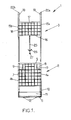
- the device 1 comprises a chassis 2 and a movable element 3 slidably mounted above said chassis 2.
- the frame 2 is of rectangular shape and consists of two uprights 4a, 4b hollow, an upper cross member 5 connecting the upper end of the uprights 4a, 4b, and a lower cross member 6 connecting the lower end of the uprights 4a , 4b.
- the frame 2 is partially closed by a mesh 7 disposed between the uprights 4a, and 4b and the upper cross member 5. This grill 7 is a means of protection to prevent anyone from crossing the frame.
- Cutouts 8 are provided in the mesh 7 to allow the attachment of handling handles 9 facilitating the handling of the device 1.
- the handles 9 are disposed substantially at the height of the hands of the operator and the equilibrium position of the device 1.
- the lower ends of the uprights 4a and 4b comprise an angled portion 10 so that the bottom rail 6 is disposed protrudingly relative to the mesh 7, as shown in FIG. figure 2 .
- the bottom rail 6 is provided with a plinth 11 that can be removable and metal studs 12 facilitating the grounding of the device 1.
- the movable element 3 has the general shape of an H, and consists of two uprights 15a and 15b, a lower cross member 16 connecting the uprights 15a and 15b, and an upper cross member 17 connecting the uprights 15a and 15b .
- the shape and dimensions of the uprights 15a and 15b are adapted so that said uprights 15a and 15b slide respectively in the hollow uprights 4a and 4b of the frame 2.
- the lower crosspiece 16 is arranged so that, when the movable element 3 is retracted as far as possible into the chassis 2, said lower crossmember 16 is as close as possible to the upper crossmember 5 of the chassis 2.
- the upper cross member 17 of the movable member 3 is arranged to leave a space between said upper cross member 17 and the uprights 15a and 15b, sufficient to clear the upper area of the opening so as to easily perform the finishing work without having to remove the protective device of the opening to be protected.
- the movable member 3 is partially closed by a mesh 18 disposed between the uprights 15a, 15b, the lower cross member 16 and the upper cross member 17.
- This mesh 18 is a means of protection to prevent anyone from crossing the movable member 3 .
- the movable element 3 comprises rectangular plates 19, assembled perpendicularly to the free ends 20a and 20b of the uprights 15a and 15b, and projecting towards the rear of the protective device 1. Such plates 19 form stops against the upper frame opening to protect and stop the stroke of the movable member 3.
- the means for adjusting the positioning of the movable member 3 above the frame 2 consist of a threaded rod 25 fixedly mounted on the lower cross member 16 of the movable member 3 and a nut. 26.
- the upper cross member 5 of the frame 2 comprises a through hole opposite the threaded rod 25 so that the latter traverses and slides in said through hole.
- the nut 26 is a butterfly nut, particularly easy to maneuver to adjust the length of the threaded rod 25 between the two crosspieces 5 and 16.
- the free end of the threaded rod 25 comprises a welded nut 27 or other welded stop device, serving as a stop against the upper cross member 5 of the frame 2 so that the threaded rod 25 is not completely removed.
- the device 1 according to the invention can be made of galvanized steel.
- the dimensions of the different parts constituting the device according to the invention are such that the width of the device and the height, once the device is unfolded, are adapted to the different widths and heights of possible openings.
- the dimensions of the frame and the movable element are chosen so that the adjustment means are provided at a height between 1.20 m and 1.50 m from the ground, so as to facilitate their access.
- the dimensions will be chosen so that the wing nut 26 is at a height of 1.30 m from the ground, at height of the operator.
- the device 1 according to the invention is particularly manageable and convenient to use, without the need to use a stepladder or ladder to install the protective device.
- the protective device 1 is disposed in front of the opening so that the frame 2 rests on the ground. Then the operator easily maneuver the wing nut 26 disposed at its height, to slide the movable member 3 above the frame 2 until the plates 19 abut against the upper frame of the opening. In this unfolded position represented on the figure 2 , the protection device 1 closes the opening to be protected.
Abstract
Description
La présente invention concerne un dispositif de protection d'une ouverture, notamment une ouverture correspondant à une cage d'ascenseur, ou à l'emplacement d'une porte ou d'une baie vitrée pendant des travaux.The present invention relates to a protection device of an opening, in particular an opening corresponding to an elevator shaft, or to the location of a door or bay window during work.
De tels dispositifs de protection sont par exemple utilisés dans le domaine du bâtiment, sur les chantiers de construction. Ils sont mis en place dans les ouvertures de manière à les obturer et barrer le passage pour empêcher une personne de franchir malencontreusement ladite ouverture et de tomber dans le vide.Such protective devices are for example used in the field of building, on construction sites. They are placed in the openings so as to close them and block the passage to prevent a person from accidentally crossing said opening and fall into the void.
Les dispositifs de protection doivent être réglables en hauteur afin de s'adapter aux différentes hauteurs d'ouverture que l'on peut trouver sur un chantier.The protection devices must be adjustable in height to adapt to the different heights of opening that can be found on a building site.
Les dispositifs de protection qui existent sur le marché sont souvent lourds et difficiles à manoeuvrer et offrent parfois une protection insuffisante. De plus, les moyens de réglage en hauteur sont en général disposés aux extrémités supérieures du dispositif, et nécessitent l'utilisation d'une échelle ou d'un escabeau pour pouvoir les atteindre et les manoeuvrer.Protective devices that exist on the market are often heavy and difficult to maneuver and sometimes offer insufficient protection. In addition, the height adjustment means are generally arranged at the upper ends of the device, and require the use of a ladder or stepladder to be able to reach and manipulate them.
La présente invention vise à remédier aux inconvénients de l'art antérieur.The present invention aims to overcome the disadvantages of the prior art.
Dans cette perspective, l'un des objectifs essentiels de la présente invention est de proposer un dispositif de protection léger et facile à manipuler tout en offrant une protection maximale.In this perspective, one of the essential objectives of the present invention is to provide a lightweight protection device and easy to handle while providing maximum protection.
Un autre objectif essentiel de la présente invention est de proposer un dispositif de protection dont les moyens de réglage en hauteur peuvent être facilement manoeuvres.Another essential objective of the present invention is to provide a protection device whose height adjustment means can be easily maneuvers.
Ces objectifs, parmi d'autres, sont atteints par la présente invention qui concerne un dispositif de protection d'une ouverture, comprenant un châssis présentant deux montants et au moins partiellement fermé par des moyens de protection disposés entre lesdits montants, caractérisé en ce que ledit dispositif de protection comprend également:
- un élément mobile monté coulissant au-dessus du châssis, comprenant deux montants agencés pour coulisser avec les montants du châssis, et au moins partiellement fermé par des moyens de protection disposés entre ses montants, et
- des moyens de réglage du positionnement de l'élément mobile au-dessus du châssis, agencés pour faire coulisser l'élément mobile au-dessus du châssis, lors de la mise en place du dispositif devant l'ouverture à protéger, jusqu'à ce que le châssis et l'élément mobile obturent ladite ouverture.
- a movable member slidably mounted above the frame, comprising two uprights arranged to slide with the uprights of the frame, and at least partially closed by means of protection arranged between its uprights, and
- means for adjusting the positioning of the mobile element above the frame, arranged to slide the movable element above the frame, during the introduction of the device in front of the opening to be protected, until that the frame and the movable member seal said opening.
Lesdits moyens de réglage sont choisis et disposés de manière à pouvoir être facilement manoeuvrés par un opérateur utilisant le dispositif selon l'invention.Said adjustment means are chosen and arranged so that they can be easily operated by an operator using the device according to the invention.
D'une manière avantageuse, le châssis du dispositif selon l'invention peut comprendre une traverse supérieure reliant les deux montants dudit châssis, l'élément mobile peut comprendre une traverse inférieure reliant les deux montants dudit élément mobile, et les moyens de réglage du positionnement de l'élément mobile peuvent être constitués d'au moins une tige filetée, la tige filetée étant montée fixe sur la traverse inférieure de l'élément mobile et traversant la traverse supérieure du châssis, et d'au moins un écrou pour régler la longueur de la tige filetée entre les deux traverses.Advantageously, the frame of the device according to the invention may comprise an upper cross member connecting the two uprights of said frame, the element mobile can comprise a lower crossbar connecting the two uprights of said movable element, and the positioning adjustment means of the movable element may consist of at least one threaded rod, the threaded rod being fixedly mounted on the lower rail of the movable member and passing through the upper cross member of the frame, and at least one nut to adjust the length of the threaded rod between the two crosspieces.
Selon une autre variante, le châssis du dispositif selon l'invention peut comprendre une traverse supérieure reliant les deux montants dudit châssis, l'élément mobile peut comprendre une traverse inférieure reliant les deux montants dudit élément mobile, et les moyens de réglage du positionnement de l'élément mobile peuvent être constitués d'au moins une tige filetée, la tige filetée étant montée fixe sur la traverse supérieure du châssis et traversant la traverse inférieure de l'élément mobile, et d'au moins un écrou pour régler la longueur de la tige filetée entre les deux traverses.According to another variant, the frame of the device according to the invention may comprise an upper crossbar connecting the two uprights of said frame, the movable element may comprise a lower crossbar connecting the two uprights of said movable element, and the adjustment means of the positioning of the movable element may consist of at least one threaded rod, the threaded rod being fixedly mounted on the upper cross member of the frame and passing through the lower cross member of the movable element, and at least one nut to adjust the length of the the threaded rod between the two sleepers.
De préférence, les moyens de réglage peuvent être prévus à une hauteur comprise entre 1,20 m et 1,90 m du sol, de manière à être facilement accessibles à un opérateur pour faciliter leur actionnement. De manière encore plus préférée, les moyens de réglage peuvent être prévus à une hauteur comprise entre 1,20 m et 1,50 m du sol, de manière à être à la hauteur de l'opérateur.Preferably, the adjustment means may be provided at a height between 1.20 m and 1.90 m from the ground, so as to be easily accessible to an operator to facilitate their actuation. Even more preferably, the adjustment means may be provided at a height between 1.20 m and 1.50 m from the ground, so as to be at the height of the operator.
De préférence, les moyens de protection peuvent être constitués d'un grillage, afin de fermer ou obturer partiellement le châssis et l'élément mobile. Il est bien évident que tout autre moyen de protection peut être utilisé, tel que des plaques entièrement fermées, métalliques, en bois ou autres.Preferably, the protection means may consist of a grid, in order to close or partially close the frame and the movable member. It is obvious that any other means of protection can be used, such as fully closed plates, metal, wood or other.
D'une manière avantageuse, le châssis peut comprendre une traverse inférieure reliant les deux montants et pourvue d'une plinthe. Cette plinthe peut être amovible afin de libérer la surface de travail au sol sans enlever le dispositif de protection de l'ouverture à protéger.Advantageously, the frame may comprise a lower crossbar connecting the two uprights and provided with a plinth. This plinth can be removable to release the working surface on the ground without removing the protective device of the opening to protect.
Avantageusement, le châssis peut être équipé de poignées facilitant sa manipulation.Advantageously, the frame can be equipped with handles facilitating its handling.
De préférence, l'élément mobile comprend une traverse supérieure reliant les deux montants et disposée de manière à laisser un espace entre ladite traverse supérieure et lesdits montants, ledit espace étant suffisant pour dégager la zone supérieure de l'ouverture, de manière à pouvoir facilement effectuer les travaux de finition sans enlever le dispositif de protection de l'ouverture à protéger.Preferably, the movable element comprises an upper cross member connecting the two uprights and arranged to leave a space between said upper crossbar and said uprights, said space being sufficient to clear the upper zone of the opening, so as to easily perform the finishing work without removing the protective device from the opening to be protected.
Avantageusement, l'élément mobile peut comprendre, aux extrémités libres de ses montants, des plaques formant des butées.Advantageously, the movable element may comprise, at the free ends of its uprights, plates forming stops.
D'une manière particulièrement préférée, le châssis peut être de forme rectangulaire, les montants du châssis étant creux, et l'élément mobile peut présenter la forme d'un H, les montants de l'élément mobile étant agencés pour coulisser dans les montants creux du châssis.In a particularly preferred manner, the frame may be rectangular in shape, the frame uprights being hollow, and the movable element may have the H-shaped, the amounts of the movable element being arranged to slide in the hollow uprights of the frame.
Ainsi, le dispositif de protection d'une ouverture selon l'invention peut être facilement transporté et manoeuvré afin de s'adapter parfaitement aux dimensions de l'ouverture à protéger pour l'obturer en garantissant la plus grande sécurité.Thus, the protection device of an opening according to the invention can be easily transported and maneuvered in order to perfectly adapt to the dimensions of the opening to be protected to close it while guaranteeing the greatest safety.
D'autres avantages et caractéristiques ressortiront mieux de la description qui va suivre d'un exemple de réalisation d'un dispositif de protection conforme à l'invention, donné à titre d'exemple non limitatif, en référence aux dessins annexés sur lesquels:
- la
figure 1 représente une vue éclatée d'un dispositif de protection selon l'invention, - la
figure 2 représente une vue en perspective du dispositif selon l'invention.
- the
figure 1 represents an exploded view of a protection device according to the invention, - the
figure 2 represents a perspective view of the device according to the invention.
En référence aux
Le dispositif 1 comprend un châssis 2 et un élément mobile 3 monté coulissant au-dessus dudit châssis 2.The device 1 comprises a
Le châssis 2 est de forme rectangulaire et est constitué de deux montants 4a, 4b creux, d'une traverse supérieure 5 reliant l'extrémité supérieure des montants 4a, 4b, et d'une traverse inférieure 6 reliant l'extrémité inférieure des montants 4a, 4b. Le châssis 2 est partiellement obturé par un grillage 7 disposé entre les montants 4a, et 4b et la traverse supérieure 5. Ce grillage 7 constitue des moyens de protection pour empêcher toute personne de traverser le châssis.The
Des découpes 8 sont prévues dans le grillage 7 pour permettre la fixation de poignées de manutention 9 facilitant la manipulation du dispositif 1. Les poignées 9 sont disposées sensiblement à hauteur des mains de l'opérateur et à la position d'équilibre du dispositif 1.
Les extrémités inférieures des montants 4a et 4b comprennent une portion en biais 10 de sorte que la traverse inférieure 6 est disposée de manière proéminente par rapport au grillage 7, comme cela est représenté sur la
L'élément mobile 3 présente la forme générale d'un H, et est constitué de deux montants 15a et 15b, d'une traverse inférieure 16 reliant les montants 15a et 15b, et d'une traverse supérieure 17 reliant les montants 15a et 15b.The movable element 3 has the general shape of an H, and consists of two
La forme et les dimensions des montants 15a et 15b sont adaptées de sorte que lesdits montants 15a et 15b coulissent respectivement dans les montants creux 4a et 4b du châssis 2.The shape and dimensions of the
La traverse inférieure 16 est disposée de sorte que, lorsque l'élément mobile 3 est rentré au maximum dans le châssis 2, ladite traverse inférieure 16 soit au plus près de la traverse supérieure 5 du châssis 2.The
La traverse supérieure 17 de l'élément mobile 3 est disposée de manière à laisser un espace entre ladite traverse supérieure 17 et les montants 15a et 15b, suffisant pour dégager la zone supérieure de l'ouverture de manière à pouvoir facilement effectuer les travaux de finition, sans avoir à sans retirer le dispositif de protection de l'ouverture à protéger.The
L'élément mobile 3 est partiellement obturé par un grillage 18 disposé entre les montants 15a, et 15b, la traverse inférieure 16 et la traverse supérieure 17. Ce grillage 18 constitue des moyens de protection pour empêcher toute personne de traverser l'élément mobile 3.The movable member 3 is partially closed by a
L'élément mobile 3 comprend des plaques rectangulaires 19, assemblées perpendiculairement aux extrémités libres 20a et 20b des montants 15a et 15b, et faisant saillie vers l'arrière du dispositif de protection 1. De telles plaques 19 forment des butées contre l'encadrement supérieur de l'ouverture à protéger et permettent de stopper la course de l'élément mobile 3.The movable element 3 comprises
Dans l'exemple représenté, les moyens de réglage du positionnement de l'élément mobile 3 au-dessus du châssis 2 sont constitués d'une tige filetée 25 montée fixe sur la traverse inférieure 16 de l'élément mobile 3 et d'un écrou 26. La traverse supérieure 5 du châssis 2 comprend un orifice traversant au regard de la tige filetée 25 de sorte que cette dernière traverse et coulisse dans ledit orifice traversant. L'écrou 26 est un écrou papillon, particulièrement aisé à manoeuvrer pour régler la longueur de la tige filetée 25 entre les deux traverses 5 et 16.In the example shown, the means for adjusting the positioning of the movable member 3 above the
L'extrémité libre de la tige filetée 25 comprend un écrou soudé 27 ou tout autre dispositif d'arrêt soudé, servant de butée contre la traverse supérieure 5 du châssis 2 pour que la tige filetée 25 ne soit pas entièrement retirée.The free end of the threaded
Il est bien évident que la disposition contraire peut être prévue, c'est-à-dire que la tige filetée peut être montée fixe sur la traverse supérieure du châssis et traverser la traverse inférieure de l'élément mobile.It is obvious that the opposite arrangement can be provided, that is to say that the threaded rod can be fixedly mounted on the upper cross member of the frame and through the lower cross member of the movable member.
Le dispositif 1 selon l'invention peut être réalisé en acier galvanisé.The device 1 according to the invention can be made of galvanized steel.
Les dimensions des différentes parties constituant le dispositif selon l'invention sont telles que la largeur du dispositif et la hauteur, une fois le dispositif déplié, sont adaptées aux différentes largeurs et hauteurs d'ouvertures possibles.The dimensions of the different parts constituting the device according to the invention are such that the width of the device and the height, once the device is unfolded, are adapted to the different widths and heights of possible openings.
Plus particulièrement, les dimensions du châssis et de l'élément mobile sont choisies de sorte que les moyens de réglage sont prévus à une hauteur comprise entre 1,20 m et 1,50 m du sol, de manière à faciliter leur accès. Par exemple, les dimensions seront choisies de sorte que l'écrou papillon 26 soit à une hauteur de 1,30 m du sol, à hauteur de l'opérateur. Ainsi, le dispositif 1 selon l'invention est particulièrement maniable et pratique à utiliser, sans qu'il soit nécessaire d'utiliser un escabeau ou une échelle pour installer le dispositif de protection.More particularly, the dimensions of the frame and the movable element are chosen so that the adjustment means are provided at a height between 1.20 m and 1.50 m from the ground, so as to facilitate their access. For example, the dimensions will be chosen so that the
Pour empêcher par exemple de pénétrer dans une cage d'ascenseur, le dispositif de protection 1 selon l'invention est disposé devant l'ouverture de sorte que le châssis 2 repose sur le sol. Puis l'opérateur manoeuvre aisément l'écrou papillon 26 disposé à sa hauteur, pour faire coulisser l'élément mobile 3 au-dessus du châssis 2 jusqu'à ce que les plaques 19 butent contre l'encadrement supérieur de l'ouverture. Dans cette position dépliée représentée sur la
Claims (10)
Applications Claiming Priority (1)
| Application Number | Priority Date | Filing Date | Title |
|---|---|---|---|
| FR0755551A FR2917110B1 (en) | 2007-06-07 | 2007-06-07 | DEVICE FOR PROTECTING AN OPENING |
Publications (2)
| Publication Number | Publication Date |
|---|---|
| EP2000613A1 true EP2000613A1 (en) | 2008-12-10 |
| EP2000613B1 EP2000613B1 (en) | 2013-11-20 |
Family
ID=38962049
Family Applications (1)
| Application Number | Title | Priority Date | Filing Date |
|---|---|---|---|
| EP08157870.0A Active EP2000613B1 (en) | 2007-06-07 | 2008-06-09 | Device for protecting an opening |
Country Status (2)
| Country | Link |
|---|---|
| EP (1) | EP2000613B1 (en) |
| FR (1) | FR2917110B1 (en) |
Cited By (5)
| Publication number | Priority date | Publication date | Assignee | Title |
|---|---|---|---|---|
| GB2456863A (en) * | 2008-01-25 | 2009-07-29 | Easi Edge Ltd | Shaft gate |
| GB2468688A (en) * | 2009-03-19 | 2010-09-22 | Slick Systems | Extendable safety barrier |
| CN106351553A (en) * | 2016-08-30 | 2017-01-25 | 李劲松 | Emergency evacuation barrier |
| CN111155776A (en) * | 2020-01-21 | 2020-05-15 | 贵州建工安顺建筑工程有限公司 | Elevator well head protector for building engineering construction |
| CN111576900A (en) * | 2020-04-23 | 2020-08-25 | 张达芬 | Safety protection device for building construction |
Families Citing this family (4)
| Publication number | Priority date | Publication date | Assignee | Title |
|---|---|---|---|---|
| FR2973413B1 (en) * | 2011-03-30 | 2015-05-15 | Gelase Havyarimana | DEVICE FOR PROTECTING AN OPENING |
| FR2997716B1 (en) * | 2012-11-05 | 2014-12-19 | Provemat | DEVICE FOR PROTECTING AN OPENING |
| FR3012494A1 (en) * | 2013-10-31 | 2015-05-01 | Copac | ELEVATOR BAY PROTECTION DEVICE |
| CN112593718A (en) * | 2020-11-17 | 2021-04-02 | 夏燕东 | Building hole anti-falling device |
Citations (4)
| Publication number | Priority date | Publication date | Assignee | Title |
|---|---|---|---|---|
| US3822850A (en) * | 1973-01-29 | 1974-07-09 | Dell Holdings Ltd | Support for construction fence |
| EP1302609A1 (en) * | 2001-09-27 | 2003-04-16 | Luis Rodriguez Gonzalez | Safety handrail for construction work. |
| US20030213205A1 (en) * | 2002-05-14 | 2003-11-20 | Mauro Muller | Adjustable security apparatus for protection of door and window openings |
| EP1598503A1 (en) * | 2003-02-26 | 2005-11-23 | Tomas Funes Gavilan | Construction safety assembly |
Family Cites Families (1)
| Publication number | Priority date | Publication date | Assignee | Title |
|---|---|---|---|---|
| DE4445271C1 (en) * | 1994-12-19 | 1996-10-10 | Vogelsang Marc | Apparatus for closing window and other structural openings |
-
2007
- 2007-06-07 FR FR0755551A patent/FR2917110B1/en not_active Expired - Fee Related
-
2008
- 2008-06-09 EP EP08157870.0A patent/EP2000613B1/en active Active
Patent Citations (4)
| Publication number | Priority date | Publication date | Assignee | Title |
|---|---|---|---|---|
| US3822850A (en) * | 1973-01-29 | 1974-07-09 | Dell Holdings Ltd | Support for construction fence |
| EP1302609A1 (en) * | 2001-09-27 | 2003-04-16 | Luis Rodriguez Gonzalez | Safety handrail for construction work. |
| US20030213205A1 (en) * | 2002-05-14 | 2003-11-20 | Mauro Muller | Adjustable security apparatus for protection of door and window openings |
| EP1598503A1 (en) * | 2003-02-26 | 2005-11-23 | Tomas Funes Gavilan | Construction safety assembly |
Cited By (7)
| Publication number | Priority date | Publication date | Assignee | Title |
|---|---|---|---|---|
| GB2456863A (en) * | 2008-01-25 | 2009-07-29 | Easi Edge Ltd | Shaft gate |
| GB2456863B (en) * | 2008-01-25 | 2012-09-26 | Easi Edge Ltd | Shaft gate |
| GB2468688A (en) * | 2009-03-19 | 2010-09-22 | Slick Systems | Extendable safety barrier |
| CN106351553A (en) * | 2016-08-30 | 2017-01-25 | 李劲松 | Emergency evacuation barrier |
| CN106351553B (en) * | 2016-08-30 | 2018-06-12 | 李劲松 | Emergency escape guardrail |
| CN111155776A (en) * | 2020-01-21 | 2020-05-15 | 贵州建工安顺建筑工程有限公司 | Elevator well head protector for building engineering construction |
| CN111576900A (en) * | 2020-04-23 | 2020-08-25 | 张达芬 | Safety protection device for building construction |
Also Published As
| Publication number | Publication date |
|---|---|
| FR2917110B1 (en) | 2009-09-25 |
| FR2917110A1 (en) | 2008-12-12 |
| EP2000613B1 (en) | 2013-11-20 |
Similar Documents
| Publication | Publication Date | Title |
|---|---|---|
| EP2000613B1 (en) | Device for protecting an opening | |
| EP2960398B1 (en) | Construction provided with an anti-fall protection equipment and corresponding inactivation method | |
| EP3010848B1 (en) | Aerial lift platform and aerial lift equipped with such a platform | |
| CA3125863A1 (en) | Aerial lift with removable control console, comprising a protection device for preventing the operator from being crushed | |
| EP3481509B1 (en) | Device providing safe access to a confined space, notably a lateral-access confined space | |
| EP3095952A1 (en) | Step plate with height-adjustable step | |
| EP1302607A1 (en) | Lifting apparatus for mounting panels to a ceiling | |
| CH704409A1 (en) | Pulley for continuous belay line system providing security in e.g. path between trees of adventure park, has blocking body with pivot part engaged by pivot to fix body to pulley body, so that blocking body is tilted to open position | |
| FR3028541A1 (en) | DEVICE FOR DETECTING SCALES OF SCAFFOLDING | |
| EP2011957A1 (en) | Ladder with permanent summit platform | |
| EP0670947B1 (en) | Gangway for crossing obstacles | |
| EP2845987B1 (en) | Step comprising a retractable shelf and a device for locking the shelf in retracted position | |
| EP2599937B1 (en) | Device for working at height easily and safely in a straight or spiral staircase | |
| EP3623540A1 (en) | Device for securing a post to a screen | |
| EP0402214B1 (en) | Safety device for the access to a ladder from an upper floor | |
| FR2728012A1 (en) | Device for preventing access to lower section of ladder with safety hoop | |
| FR2931498A1 (en) | Cross beam mounting device for guard rail, has mobile plate whose maintenance finger partially closes inlet of reception notch of fixed plate in closed position and prevents lateral extraction of introduced cross beam in closed position | |
| FR3020351A1 (en) | DEVICE FOR LOADING WASTE BINS FROM A PLATFORM | |
| FR2926575A1 (en) | METHOD OF ASSEMBLING AND DISASSEMBLING SAFELY OF A ROLLING SCAFFOLDING, SAFETY MOUNTING BRACKETS USED AND SCAFFOLD OBTAINED | |
| EP3509798B1 (en) | Portable building-site workbench | |
| FR2947849A1 (en) | Support leg for e.g. rapid scaffold, in building site, has blocking system occupying sliding position in which teeth are at distance from tubes and blocking position in which teeth are supported against one tube | |
| FR2817902A1 (en) | Secure locking device for access to ladder safety hoop comprises movable cover with panel, covering ladder immediately below hoop, carrying hoop obturator at upper end | |
| FR3012494A1 (en) | ELEVATOR BAY PROTECTION DEVICE | |
| FR2997716A1 (en) | Protection device for opening in partition of building, has adjustment unit for adjusting position of blocking element moving in translation with respect to frame, where element includes fingers supported under upper edge of opening | |
| FR3088690A1 (en) | LOCKING SYSTEM FOR A MOVEMENT BETWEEN A HOLLOW PROFILE AND A WALL |
Legal Events
| Date | Code | Title | Description |
|---|---|---|---|
| PUAI | Public reference made under article 153(3) epc to a published international application that has entered the european phase |
Free format text: ORIGINAL CODE: 0009012 |
|
| AK | Designated contracting states |
Kind code of ref document: A1 Designated state(s): AT BE BG CH CY CZ DE DK EE ES FI FR GB GR HR HU IE IS IT LI LT LU LV MC MT NL NO PL PT RO SE SI SK TR |
|
| AX | Request for extension of the european patent |
Extension state: AL BA MK RS |
|
| 17P | Request for examination filed |
Effective date: 20090610 |
|
| AKX | Designation fees paid |
Designated state(s): AT BE BG CH CY CZ DE DK EE ES FI FR GB GR HR HU IE IS IT LI LT LU LV MC MT NL NO PL PT RO SE SI SK TR |
|
| 17Q | First examination report despatched |
Effective date: 20090807 |
|
| RBV | Designated contracting states (corrected) |
Designated state(s): AT BE BG CH CY CZ DE DK EE ES FI GB GR HR HU IE IS IT LI LT LU LV MC MT NL NO PL PT RO SE SI SK TR |
|
| GRAP | Despatch of communication of intention to grant a patent |
Free format text: ORIGINAL CODE: EPIDOSNIGR1 |
|
| INTG | Intention to grant announced |
Effective date: 20130703 |
|
| RAP1 | Party data changed (applicant data changed or rights of an application transferred) |
Owner name: HAVYARIMANA, GELASE M. |
|
| RIN1 | Information on inventor provided before grant (corrected) |
Inventor name: HAVYARIMANA, GELASE M. |
|
| GRAS | Grant fee paid |
Free format text: ORIGINAL CODE: EPIDOSNIGR3 |
|
| GRAA | (expected) grant |
Free format text: ORIGINAL CODE: 0009210 |
|
| AK | Designated contracting states |
Kind code of ref document: B1 Designated state(s): AT BE BG CH CY CZ DE DK EE ES FI GB GR HR HU IE IS IT LI LT LU LV MC MT NL NO PL PT RO SE SI SK TR |
|
| REG | Reference to a national code |
Ref country code: GB Ref legal event code: FG4D Free format text: NOT ENGLISH |
|
| REG | Reference to a national code |
Ref country code: CH Ref legal event code: EP |
|
| REG | Reference to a national code |
Ref country code: AT Ref legal event code: REF Ref document number: 641765 Country of ref document: AT Kind code of ref document: T Effective date: 20131215 |
|
| REG | Reference to a national code |
Ref country code: IE Ref legal event code: FG4D Free format text: LANGUAGE OF EP DOCUMENT: FRENCH |
|
| REG | Reference to a national code |
Ref country code: DE Ref legal event code: R096 Ref document number: 602008028800 Country of ref document: DE Effective date: 20140116 |
|
| REG | Reference to a national code |
Ref country code: NL Ref legal event code: VDEP Effective date: 20131120 |
|
| REG | Reference to a national code |
Ref country code: AT Ref legal event code: MK05 Ref document number: 641765 Country of ref document: AT Kind code of ref document: T Effective date: 20131120 |
|
| REG | Reference to a national code |
Ref country code: LT Ref legal event code: MG4D |
|
| PG25 | Lapsed in a contracting state [announced via postgrant information from national office to epo] |
Ref country code: FI Free format text: LAPSE BECAUSE OF FAILURE TO SUBMIT A TRANSLATION OF THE DESCRIPTION OR TO PAY THE FEE WITHIN THE PRESCRIBED TIME-LIMIT Effective date: 20131120 Ref country code: SE Free format text: LAPSE BECAUSE OF FAILURE TO SUBMIT A TRANSLATION OF THE DESCRIPTION OR TO PAY THE FEE WITHIN THE PRESCRIBED TIME-LIMIT Effective date: 20131120 Ref country code: IS Free format text: LAPSE BECAUSE OF FAILURE TO SUBMIT A TRANSLATION OF THE DESCRIPTION OR TO PAY THE FEE WITHIN THE PRESCRIBED TIME-LIMIT Effective date: 20140320 Ref country code: NL Free format text: LAPSE BECAUSE OF FAILURE TO SUBMIT A TRANSLATION OF THE DESCRIPTION OR TO PAY THE FEE WITHIN THE PRESCRIBED TIME-LIMIT Effective date: 20131120 Ref country code: NO Free format text: LAPSE BECAUSE OF FAILURE TO SUBMIT A TRANSLATION OF THE DESCRIPTION OR TO PAY THE FEE WITHIN THE PRESCRIBED TIME-LIMIT Effective date: 20140220 Ref country code: LT Free format text: LAPSE BECAUSE OF FAILURE TO SUBMIT A TRANSLATION OF THE DESCRIPTION OR TO PAY THE FEE WITHIN THE PRESCRIBED TIME-LIMIT Effective date: 20131120 Ref country code: HR Free format text: LAPSE BECAUSE OF FAILURE TO SUBMIT A TRANSLATION OF THE DESCRIPTION OR TO PAY THE FEE WITHIN THE PRESCRIBED TIME-LIMIT Effective date: 20131120 |
|
| PG25 | Lapsed in a contracting state [announced via postgrant information from national office to epo] |
Ref country code: AT Free format text: LAPSE BECAUSE OF FAILURE TO SUBMIT A TRANSLATION OF THE DESCRIPTION OR TO PAY THE FEE WITHIN THE PRESCRIBED TIME-LIMIT Effective date: 20131120 Ref country code: LV Free format text: LAPSE BECAUSE OF FAILURE TO SUBMIT A TRANSLATION OF THE DESCRIPTION OR TO PAY THE FEE WITHIN THE PRESCRIBED TIME-LIMIT Effective date: 20131120 Ref country code: ES Free format text: LAPSE BECAUSE OF FAILURE TO SUBMIT A TRANSLATION OF THE DESCRIPTION OR TO PAY THE FEE WITHIN THE PRESCRIBED TIME-LIMIT Effective date: 20131120 |
|
| PG25 | Lapsed in a contracting state [announced via postgrant information from national office to epo] |
Ref country code: PT Free format text: LAPSE BECAUSE OF FAILURE TO SUBMIT A TRANSLATION OF THE DESCRIPTION OR TO PAY THE FEE WITHIN THE PRESCRIBED TIME-LIMIT Effective date: 20140320 |
|
| PG25 | Lapsed in a contracting state [announced via postgrant information from national office to epo] |
Ref country code: EE Free format text: LAPSE BECAUSE OF FAILURE TO SUBMIT A TRANSLATION OF THE DESCRIPTION OR TO PAY THE FEE WITHIN THE PRESCRIBED TIME-LIMIT Effective date: 20131120 |
|
| REG | Reference to a national code |
Ref country code: DE Ref legal event code: R026 Ref document number: 602008028800 Country of ref document: DE |
|
| PLBI | Opposition filed |
Free format text: ORIGINAL CODE: 0009260 |
|
| PG25 | Lapsed in a contracting state [announced via postgrant information from national office to epo] |
Ref country code: SK Free format text: LAPSE BECAUSE OF FAILURE TO SUBMIT A TRANSLATION OF THE DESCRIPTION OR TO PAY THE FEE WITHIN THE PRESCRIBED TIME-LIMIT Effective date: 20131120 Ref country code: PL Free format text: LAPSE BECAUSE OF FAILURE TO SUBMIT A TRANSLATION OF THE DESCRIPTION OR TO PAY THE FEE WITHIN THE PRESCRIBED TIME-LIMIT Effective date: 20131120 Ref country code: RO Free format text: LAPSE BECAUSE OF FAILURE TO SUBMIT A TRANSLATION OF THE DESCRIPTION OR TO PAY THE FEE WITHIN THE PRESCRIBED TIME-LIMIT Effective date: 20131120 Ref country code: CZ Free format text: LAPSE BECAUSE OF FAILURE TO SUBMIT A TRANSLATION OF THE DESCRIPTION OR TO PAY THE FEE WITHIN THE PRESCRIBED TIME-LIMIT Effective date: 20131120 |
|
| 26 | Opposition filed |
Opponent name: IDEE BAT MEDITERRANEE Effective date: 20140814 |
|
| PG25 | Lapsed in a contracting state [announced via postgrant information from national office to epo] |
Ref country code: DK Free format text: LAPSE BECAUSE OF FAILURE TO SUBMIT A TRANSLATION OF THE DESCRIPTION OR TO PAY THE FEE WITHIN THE PRESCRIBED TIME-LIMIT Effective date: 20131120 |
|
| PLAX | Notice of opposition and request to file observation + time limit sent |
Free format text: ORIGINAL CODE: EPIDOSNOBS2 |
|
| REG | Reference to a national code |
Ref country code: DE Ref legal event code: R026 Ref document number: 602008028800 Country of ref document: DE Effective date: 20140814 |
|
| PG25 | Lapsed in a contracting state [announced via postgrant information from national office to epo] |
Ref country code: MC Free format text: LAPSE BECAUSE OF FAILURE TO SUBMIT A TRANSLATION OF THE DESCRIPTION OR TO PAY THE FEE WITHIN THE PRESCRIBED TIME-LIMIT Effective date: 20131120 |
|
| PG25 | Lapsed in a contracting state [announced via postgrant information from national office to epo] |
Ref country code: SI Free format text: LAPSE BECAUSE OF FAILURE TO SUBMIT A TRANSLATION OF THE DESCRIPTION OR TO PAY THE FEE WITHIN THE PRESCRIBED TIME-LIMIT Effective date: 20131120 |
|
| PLAF | Information modified related to communication of a notice of opposition and request to file observations + time limit |
Free format text: ORIGINAL CODE: EPIDOSCOBS2 |
|
| REG | Reference to a national code |
Ref country code: IE Ref legal event code: MM4A |
|
| PLBB | Reply of patent proprietor to notice(s) of opposition received |
Free format text: ORIGINAL CODE: EPIDOSNOBS3 |
|
| PG25 | Lapsed in a contracting state [announced via postgrant information from national office to epo] |
Ref country code: IE Free format text: LAPSE BECAUSE OF NON-PAYMENT OF DUE FEES Effective date: 20140609 |
|
| REG | Reference to a national code |
Ref country code: DE Ref legal event code: R100 Ref document number: 602008028800 Country of ref document: DE |
|
| PLCK | Communication despatched that opposition was rejected |
Free format text: ORIGINAL CODE: EPIDOSNREJ1 |
|
| PG25 | Lapsed in a contracting state [announced via postgrant information from national office to epo] |
Ref country code: MT Free format text: LAPSE BECAUSE OF FAILURE TO SUBMIT A TRANSLATION OF THE DESCRIPTION OR TO PAY THE FEE WITHIN THE PRESCRIBED TIME-LIMIT Effective date: 20131120 |
|
| PLBN | Opposition rejected |
Free format text: ORIGINAL CODE: 0009273 |
|
| STAA | Information on the status of an ep patent application or granted ep patent |
Free format text: STATUS: OPPOSITION REJECTED |
|
| 27O | Opposition rejected |
Effective date: 20151211 |
|
| PG25 | Lapsed in a contracting state [announced via postgrant information from national office to epo] |
Ref country code: BG Free format text: LAPSE BECAUSE OF FAILURE TO SUBMIT A TRANSLATION OF THE DESCRIPTION OR TO PAY THE FEE WITHIN THE PRESCRIBED TIME-LIMIT Effective date: 20131120 |
|
| PG25 | Lapsed in a contracting state [announced via postgrant information from national office to epo] |
Ref country code: CY Free format text: LAPSE BECAUSE OF FAILURE TO SUBMIT A TRANSLATION OF THE DESCRIPTION OR TO PAY THE FEE WITHIN THE PRESCRIBED TIME-LIMIT Effective date: 20131120 Ref country code: GR Free format text: LAPSE BECAUSE OF FAILURE TO SUBMIT A TRANSLATION OF THE DESCRIPTION OR TO PAY THE FEE WITHIN THE PRESCRIBED TIME-LIMIT Effective date: 20140221 |
|
| PG25 | Lapsed in a contracting state [announced via postgrant information from national office to epo] |
Ref country code: TR Free format text: LAPSE BECAUSE OF FAILURE TO SUBMIT A TRANSLATION OF THE DESCRIPTION OR TO PAY THE FEE WITHIN THE PRESCRIBED TIME-LIMIT Effective date: 20131120 Ref country code: HU Free format text: LAPSE BECAUSE OF FAILURE TO SUBMIT A TRANSLATION OF THE DESCRIPTION OR TO PAY THE FEE WITHIN THE PRESCRIBED TIME-LIMIT; INVALID AB INITIO Effective date: 20080609 |
|
| PGFP | Annual fee paid to national office [announced via postgrant information from national office to epo] |
Ref country code: DE Payment date: 20201221 Year of fee payment: 13 |
|
| REG | Reference to a national code |
Ref country code: DE Ref legal event code: R119 Ref document number: 602008028800 Country of ref document: DE |
|
| PG25 | Lapsed in a contracting state [announced via postgrant information from national office to epo] |
Ref country code: DE Free format text: LAPSE BECAUSE OF NON-PAYMENT OF DUE FEES Effective date: 20220101 |
|
| PGFP | Annual fee paid to national office [announced via postgrant information from national office to epo] |
Ref country code: GB Payment date: 20220727 Year of fee payment: 15 |
|
| PGFP | Annual fee paid to national office [announced via postgrant information from national office to epo] |
Ref country code: LU Payment date: 20230915 Year of fee payment: 16 Ref country code: IT Payment date: 20230915 Year of fee payment: 16 Ref country code: CH Payment date: 20230919 Year of fee payment: 16 |
|
| PGFP | Annual fee paid to national office [announced via postgrant information from national office to epo] |
Ref country code: BE Payment date: 20230914 Year of fee payment: 16 |
|
| GBPC | Gb: european patent ceased through non-payment of renewal fee |
Effective date: 20230609 |