EP1598502A2 - Tile coating apparatus for flooring - Google Patents

Tile coating apparatus for flooring Download PDF

Info

Publication number
EP1598502A2
EP1598502A2 EP05075022A EP05075022A EP1598502A2 EP 1598502 A2 EP1598502 A2 EP 1598502A2 EP 05075022 A EP05075022 A EP 05075022A EP 05075022 A EP05075022 A EP 05075022A EP 1598502 A2 EP1598502 A2 EP 1598502A2
Authority
EP
European Patent Office
Prior art keywords
tile
roll
adhesive
dispensing
transfer
Prior art date
Legal status (The legal status is an assumption and is not a legal conclusion. Google has not performed a legal analysis and makes no representation as to the accuracy of the status listed.)
Withdrawn
Application number
EP05075022A
Other languages
German (de)
French (fr)
Other versions
EP1598502A3 (en
Inventor
Albert D'hondt
Current Assignee (The listed assignees may be inaccurate. Google has not performed a legal analysis and makes no representation or warranty as to the accuracy of the list.)
Individual
Original Assignee
Individual
Priority date (The priority date is an assumption and is not a legal conclusion. Google has not performed a legal analysis and makes no representation as to the accuracy of the date listed.)
Filing date
Publication date
Application filed by Individual filed Critical Individual
Priority to EP05075022A priority Critical patent/EP1598502A3/en
Publication of EP1598502A2 publication Critical patent/EP1598502A2/en
Publication of EP1598502A3 publication Critical patent/EP1598502A3/en
Withdrawn legal-status Critical Current

Links

Images

Classifications

    • BPERFORMING OPERATIONS; TRANSPORTING
    • B05SPRAYING OR ATOMISING IN GENERAL; APPLYING FLUENT MATERIALS TO SURFACES, IN GENERAL
    • B05CAPPARATUS FOR APPLYING FLUENT MATERIALS TO SURFACES, IN GENERAL
    • B05C11/00Component parts, details or accessories not specifically provided for in groups B05C1/00 - B05C9/00
    • B05C11/10Storage, supply or control of liquid or other fluent material; Recovery of excess liquid or other fluent material
    • B05C11/1002Means for controlling supply, i.e. flow or pressure, of liquid or other fluent material to the applying apparatus, e.g. valves
    • B05C11/1034Means for controlling supply, i.e. flow or pressure, of liquid or other fluent material to the applying apparatus, e.g. valves specially designed for conducting intermittent application of small quantities, e.g. drops, of coating material
    • BPERFORMING OPERATIONS; TRANSPORTING
    • B05SPRAYING OR ATOMISING IN GENERAL; APPLYING FLUENT MATERIALS TO SURFACES, IN GENERAL
    • B05CAPPARATUS FOR APPLYING FLUENT MATERIALS TO SURFACES, IN GENERAL
    • B05C5/00Apparatus in which liquid or other fluent material is projected, poured or allowed to flow on to the surface of the work
    • B05C5/02Apparatus in which liquid or other fluent material is projected, poured or allowed to flow on to the surface of the work the liquid or other fluent material being discharged through an outlet orifice by pressure, e.g. from an outlet device in contact or almost in contact, with the work
    • B05C5/0254Coating heads with slot-shaped outlet
    • B05C5/0258Coating heads with slot-shaped outlet flow controlled, e.g. by a valve
    • BPERFORMING OPERATIONS; TRANSPORTING
    • B05SPRAYING OR ATOMISING IN GENERAL; APPLYING FLUENT MATERIALS TO SURFACES, IN GENERAL
    • B05CAPPARATUS FOR APPLYING FLUENT MATERIALS TO SURFACES, IN GENERAL
    • B05C5/00Apparatus in which liquid or other fluent material is projected, poured or allowed to flow on to the surface of the work
    • B05C5/02Apparatus in which liquid or other fluent material is projected, poured or allowed to flow on to the surface of the work the liquid or other fluent material being discharged through an outlet orifice by pressure, e.g. from an outlet device in contact or almost in contact, with the work
    • B05C5/027Coating heads with several outlets, e.g. aligned transversally to the moving direction of a web to be coated
    • B05C5/0275Coating heads with several outlets, e.g. aligned transversally to the moving direction of a web to be coated flow controlled, e.g. by a valve
    • EFIXED CONSTRUCTIONS
    • E04BUILDING
    • E04FFINISHING WORK ON BUILDINGS, e.g. STAIRS, FLOORS
    • E04F21/00Implements for finishing work on buildings
    • E04F21/02Implements for finishing work on buildings for applying plasticised masses to surfaces, e.g. plastering walls
    • E04F21/023Implements for finishing work on buildings for applying plasticised masses to surfaces, e.g. plastering walls for applying adhesive, e.g. glue or mortar, on the covering elements, in particular tiles
    • EFIXED CONSTRUCTIONS
    • E04BUILDING
    • E04FFINISHING WORK ON BUILDINGS, e.g. STAIRS, FLOORS
    • E04F21/00Implements for finishing work on buildings
    • E04F21/02Implements for finishing work on buildings for applying plasticised masses to surfaces, e.g. plastering walls
    • E04F21/06Implements for applying plaster, insulating material, or the like
    • BPERFORMING OPERATIONS; TRANSPORTING
    • B05SPRAYING OR ATOMISING IN GENERAL; APPLYING FLUENT MATERIALS TO SURFACES, IN GENERAL
    • B05CAPPARATUS FOR APPLYING FLUENT MATERIALS TO SURFACES, IN GENERAL
    • B05C5/00Apparatus in which liquid or other fluent material is projected, poured or allowed to flow on to the surface of the work
    • B05C5/02Apparatus in which liquid or other fluent material is projected, poured or allowed to flow on to the surface of the work the liquid or other fluent material being discharged through an outlet orifice by pressure, e.g. from an outlet device in contact or almost in contact, with the work
    • B05C5/0208Apparatus in which liquid or other fluent material is projected, poured or allowed to flow on to the surface of the work the liquid or other fluent material being discharged through an outlet orifice by pressure, e.g. from an outlet device in contact or almost in contact, with the work for applying liquid or other fluent material to separate articles
    • BPERFORMING OPERATIONS; TRANSPORTING
    • B05SPRAYING OR ATOMISING IN GENERAL; APPLYING FLUENT MATERIALS TO SURFACES, IN GENERAL
    • B05CAPPARATUS FOR APPLYING FLUENT MATERIALS TO SURFACES, IN GENERAL
    • B05C5/00Apparatus in which liquid or other fluent material is projected, poured or allowed to flow on to the surface of the work
    • B05C5/02Apparatus in which liquid or other fluent material is projected, poured or allowed to flow on to the surface of the work the liquid or other fluent material being discharged through an outlet orifice by pressure, e.g. from an outlet device in contact or almost in contact, with the work
    • B05C5/0225Apparatus in which liquid or other fluent material is projected, poured or allowed to flow on to the surface of the work the liquid or other fluent material being discharged through an outlet orifice by pressure, e.g. from an outlet device in contact or almost in contact, with the work characterised by flow controlling means, e.g. valves, located proximate the outlet
    • B05C5/0229Apparatus in which liquid or other fluent material is projected, poured or allowed to flow on to the surface of the work the liquid or other fluent material being discharged through an outlet orifice by pressure, e.g. from an outlet device in contact or almost in contact, with the work characterised by flow controlling means, e.g. valves, located proximate the outlet the valve being a gate valve or a sliding valve
    • B05C5/0233Apparatus in which liquid or other fluent material is projected, poured or allowed to flow on to the surface of the work the liquid or other fluent material being discharged through an outlet orifice by pressure, e.g. from an outlet device in contact or almost in contact, with the work characterised by flow controlling means, e.g. valves, located proximate the outlet the valve being a gate valve or a sliding valve rotating valve, e.g. rotating perforated cylinder
    • BPERFORMING OPERATIONS; TRANSPORTING
    • B05SPRAYING OR ATOMISING IN GENERAL; APPLYING FLUENT MATERIALS TO SURFACES, IN GENERAL
    • B05CAPPARATUS FOR APPLYING FLUENT MATERIALS TO SURFACES, IN GENERAL
    • B05C9/00Apparatus or plant for applying liquid or other fluent material to surfaces by means not covered by any preceding group, or in which the means of applying the liquid or other fluent material is not important
    • B05C9/08Apparatus or plant for applying liquid or other fluent material to surfaces by means not covered by any preceding group, or in which the means of applying the liquid or other fluent material is not important for applying liquid or other fluent material and performing an auxiliary operation
    • B05C9/10Apparatus or plant for applying liquid or other fluent material to surfaces by means not covered by any preceding group, or in which the means of applying the liquid or other fluent material is not important for applying liquid or other fluent material and performing an auxiliary operation the auxiliary operation being performed before the application

Definitions

  • the tile path is typically formed of support/guide rails passing below the adhesive dispenser whereas the tile transfer means comprise a hydraulic jack connected with either a tile pusher or a tile drawer bar (depending on the desired orientation of the hydraulic cylinder displacement incl. the proper mounting of the jack), by which the tile is moved at suitable speed underneath the adhesive dispenser (forward stroke of the hydraulic cylinder).
  • the tile transfer means comprise a hydraulic jack connected with either a tile pusher or a tile drawer bar (depending on the desired orientation of the hydraulic cylinder displacement incl. the proper mounting of the jack), by which the tile is moved at suitable speed underneath the adhesive dispenser (forward stroke of the hydraulic cylinder).
  • the entry side of the tile will hit a first switch placed along the guiding rail at a position corresponding with the location of the dispensing orifices and thereafter a second switch placed at a predetermined distance behind the first switch; said distance determines the width of the uncoated tile rim, since switch setting is such that rotation of the dispensing roll is actuated only when both switches are simultaneously contacted by the moving tile (side faces). After that the full tile length is passed below the dispensing orifices the hydraulic piston is quickly withdrawn towards is tile feeding start position and the cycle is repeated with a subsequent tile.

Landscapes

  • Engineering & Computer Science (AREA)
  • Architecture (AREA)
  • Civil Engineering (AREA)
  • Structural Engineering (AREA)
  • Coating Apparatus (AREA)

Abstract

The invention provides in a compact and mobile apparatus for applying a coating of adhesive material (cementitious etc.) to the bonding surface of tiles, in particular flooring tiles, at a desired tile laying location, whereby the tile coating operation is carried out in a controlled and automatic manner.
The apparatus has a self-supporting frame, preferably equipped with rollers for moving the same to a required flooring location, and assembled thereto it comprises the combination of an adhesive holding tank (1) housing a dispenser roll (2) arranged in the semi-cylindrical tank bottom, tile transfer means (F2) , tile stacking means (4) and driving incl. power connection means. According to a key feature of the invention the actuation of the adhesive roll applicator is established and controlled in selective synchronicity with the displacement of the tiles resp. movement of the tile transfer means.
The tile transfer means and the dispenser roll are operatively connected in a suitable manner and may be driven by hydraulic or electro-mechanical means. The selective actuation thereof is advantageously controlled by contact switches or detector elements positioned at suitable locations along the tile displacement path extending from the tile stack magazine to underneath and past the dispenser roll untill a tile discharge position at the end of the track. The tile transfer means may comprise a hydraulic piston unit or an endless belt with driven rollers.

Description

The present application is a continuation of BE provisional application No. 2001/0003 related to a a method and system of laying flooring tiles, the full content of which is incorporated herein by reference.
Field and object of the invention
The present invention pertains to the field of tile laying such as flooring and more generally to the operation of laying tiles on a floor or wall surface.
More in particular, the invention is directed to a reliable and handsome apparatus for the automatic dispensing of adhesive material (adhesive cement and other suitable organic and/or inorganic bonding materials) onto tile surfaces in a controlled manner.
Furthermore the invention provides an improved system of tile laying, especially flooring, which involves the use of said apparatus for applying a controllable amount of adhesive onto the laying surface of tiles, thereby allowing to render the conventional tile laying or flooring method more efficient, better controlled and less time consuming.
Background of the invention
Up to now the conventional practice of covering floor or wall surfaces with tiles, in particular the known art of flooring, basically consists in preparing a sufficiently flat surface such as floor and wall surfaces, spreading a layer of adhesive cement or mortar or other binder (cementitious, inorganic or organic) onto the surface to be covered and thereafter disposing tiles in the adhesive or binder layer. The operation of spreading adhesive and laying tiles is normally carried out in successive incremental surface coverage steps, until the whole floor or wall surface area is completed.
A drawback of the traditional flooring method is that the application of adhesive cement onto the floor surface has to be done manually. Moreover, the surface portion covered in one adhesive spreading/tile laying step should not be too large. Indeed, the tile laying operator must not step into the adhesive layer. In addition the binding quality of the adhesive cement spread at once onto a large a surface area may become poor (at least in the remaining last surface areas to be floored), because of drying out and too long exposure to the atmosphere before being covered with tiles.
Another disadvantage is that the layer of adhesive cement spread onto the flooring surface by manual labor is not uniform in thickness. As a rule the adhesive spreading step is followed by a scraping operation, which requires additional labour.
To solve the latter problems there have been made several proposals to mechanize the operation of spreading adhesive or even flooring material on a horizontal surface. This is achieved by means of a dispensing device comprising a container mounted on a movable frame and optionally including roller/squeezing or scraping means to equalize the layer of semi-liquid or viscous binder material applied on the surface. Devices of this kind are disclosed in patent pubications US-A-5275662, US-A-4575279 and EP-A-471863.
These devices, however, do not solve the problems related to stepwise surface coverage and possible deterioration of binder layer adhesiveness when spread on large surface areas. In the prior art the above mentioned problems w.r.t conventional flooring have been indicated already in german patent document DE-A-3726841.
Document DE-A-3726841 describes an equipment for spreading adhesive cement or mortar on tiles with the aim of reducing expenditure of labour in flooring. The equipment comprises a table frame assembly comprising a dispensing tank, a tile magazine and a tile loading resp. transfer system mounted on top of the table. The dispensing tank is an open container filled with adhesive paste. The tile transfer means comprise tile guiding rails and a push rod sliding in a slot: by moving the push rod forward the undermost tile is pushed out of the stack in the tile magazine and moved underneath the cement paste filled container where a layer of adhesive cement is applied on the tile surface. On the leaving side of the container a toothed slat or drag plate is mounted which scrapes off excess cement and forms strips of cement paste on the tile. Successive tiles are passed underneath the dispensing tank by repeated sliding movement of the push rod.
To the inventor's knowledge the type of device proposed in DE-A-3726841 never came to industrial applications because of a number of major technical shortcomings.
The prior art cement applicator remains basically a manually operated device, which is not capable of delivering coated tiles in a controlled and automatic way. Moreover, the open mechanical cement applicator gives rise to important spill-over of cement paste and coating uniformity is difficult to maintain, since necessary adjustments between cement dispensing and tile transfer is not ensured.
Summary of the invention
The present invention provides an apparatus for applying a cementitious or similar adhesive paste to an exposed or laying surface of tiles, in particular flooring tiles, which comprises a table frame, preferably mobile, on which is mounted a dispensing container or tank filled with adhesive material, a tile magazine and a tile transfer mechanism for moving tile after tile underneath the container dispenser or applicator, the apparatus being characterised in that the dispensing container houses a rotatable dispensing roll which is rotated in selective synchronicity with the linear displacement of the tiles resp. tile transfer means.
In this connection selective synchronicity means that the adhesive applicator roll or drum will rotate only when a tile is actually moving below the underside of the dispensing tank, thus underneath the openings or slits located in the bottom part of the dispensing tank, which openings are shut off by a tile when not moving.
The drive means of the dispensing roll may be coupled directly with the drive means of the tile transfer means, and preferably the rotational motion of the dispensing roll and the transfer movement of the tiles are actuated by a common/single drive means. Said drive means may e.g. comprise a chain drive and/or belt drive actuated by one electrical motor.
In case of using separate electro-drives for tile transfer and applicator roll they are steered in selective synchronicity.
Another preferred drive embodiment includes an electro-hydraulic system comprising a hydraulic motor connected to the shaft of the rotatable dispensing roll and furthermore a hydraulic jack for actuating the tile transfer means. Preferably a second hydraulic jack is provided for positioning and supporting the tiles and/or the tile magazine, in both horizontal and vertical directions. In the latter case the tile magazine is preferably arranged to be lifted such that the upper tile is brought into a feeding position being about level with the mechanism of tile transfer. In this embodiment all the hydraulic actuation means may be powered by a single electro-hydraulic group forming part of the tile coating apparatus.
Detailed description of the invention
The objects and advantages of the invention will become more apparent from the description of two exemplary embodiments detailed hereinbelow. It is to be understood that the exemplified embodiments are in no way limiting the scope of the invention, which is solely determined by the features of the appended claims.
The detailed description makes reference to the following drawings:
  • Figure 1 gives a schematic view of major tile movement steps in accordance with a first embodiment of the invention.
  • Figure 2 shows a preferred arrangement of the adhesive dispensing device forming part of the apparatus according to the invention.
  • Figures 3 and 4 depict further details of the dispensing device shown in figure 2.
  • Figure 5 illustrates the overall lay-out of an inventive apparatus according to the first embodiment, including a longitudinal view, a side view and a top view,
  • Figure 6 shows a few pictures of an apparatus designed according to the embodiment illustrated in figure 5.
  • Figure 7 gives a schematic view of a second embodiment of the invention.
  • Figure 8 shows further apparatus details of said second embodiment.
  • Referring to figure 1, there is shown the preferred lay-out of a tile coating operation according to a first embodiment of the invention. Input of tiles 3 is done from a tile stack 4 retained in a tile magazine. In this preferred embodiment the tile magazine of the apparatus is supported by a hydraulic carrier (not shown), which in use of the apparatus lifts the tile stack (arrow F1) to a feeding/transfer position. By means of suitable transfer and guiding means the upper tile is then transferred (arrow F2) in the horizontal direction so as to pass underneath the coating dispensing unit 1 filled with adhesive 6. Upon movement of the tile transfer means resp. displacement of a tile below the adhesive dispenser the applicator roll 3 begins to rotate and thereby forces adhesive paste through bottom orifices or slits 5 onto the tile surface. The coated tile is pushed towards a discharge position (arrow F3) by a newly transferred tile supplied from stack 4. At the transfer position the coated tile is constantly or intermittently removed for being laid on a floor surface. The apparatus, i.e. rotation of the coater roll and the actuation of the tile transfer means, automatically stops when a coated tile is not removed at the tile discharge position; for this purpose a suitable electro-switch is provided at a desired end location of the tile displacement path. When tile displacement stops or is interrupted for any reason, the dispenser roll will automatically be arrested, such that spill-over of adhesive is prevented. Also when there no tile underneath the adhesive applicator, e.g. during transfer of a "first" tile from the tile magazine towards the adhesive applicator, the dispenser roll will not be actuated for rotation.
    An additional preferred feature of the "selective" synchronous actuation of tile transfer and dispenser roll consists in the provision of supplementary switching means along the tile displacement path, typically at a location close to the adhesive dispensing orifices but at an adjustable distance therefrom, such that rotation of the dispenser roll is selectively actuated resp. temporarily interrupted during tile displacement. By this preferred feature it is possible to apply adhesive paste onto the tile surface only over a selected length thereof, for instance by adjusting a switch setting for roll rotation leaving an entry portion and an exit portion of the tile uncoated. This is advantageous not only for avoiding adhesive spill-over but also for the subsequent process of tile laying. Indeed, by providing uncoated rim areas along the tile sides the step of tile laying resp. flooring is rendered more uniform and cleaner, because no ahesive material is pressed upwards between and over adjoining tiles; moreover, the tile joints can be kept clear such that the finishing step of joint filling afterwards may be effected in a proper way with desired colour aspect uniformity.
    With respect to the apparatus embodiment having hydraulic means for tile transfer, the tile path is typically formed of support/guide rails passing below the adhesive dispenser whereas the tile transfer means comprise a hydraulic jack connected with either a tile pusher or a tile drawer bar (depending on the desired orientation of the hydraulic cylinder displacement incl. the proper mounting of the jack), by which the tile is moved at suitable speed underneath the adhesive dispenser (forward stroke of the hydraulic cylinder). The entry side of the tile will hit a first switch placed along the guiding rail at a position corresponding with the location of the dispensing orifices and thereafter a second switch placed at a predetermined distance behind the first switch; said distance determines the width of the uncoated tile rim, since switch setting is such that rotation of the dispensing roll is actuated only when both switches are simultaneously contacted by the moving tile (side faces). After that the full tile length is passed below the dispensing orifices the hydraulic piston is quickly withdrawn towards is tile feeding start position and the cycle is repeated with a subsequent tile.
    The preferred design of the adhesive applicator unit of the inventive apparatus is shown in figure 2 with further details given in figures 3 and 4. Adhesive material 6 contained in upper containing part of dispensing tank 1 is filled to a level above the heigth of dispensing roll 2. The longitudinal dimension of the holding tank resp. of the roll axis, is perpendicular to the transfer direction (F1, F2) of the tiles 3 and has a length which preferably is not smaller than the width of the tiles to be coated with adhesive. The lower part of tank 1 has a hemispherical shape which roughly matches the cylinder form of dispensing roll 2, the latter being disposed in the tank in an appropiate manner. Typically the roll is shaped as a hollow drum or cylinder having two opposed end faces, at least one thereof being provided with bearing elements rotatably supported in a side wall of the tank or in a fixed frame part of the apparatus. One bearing end face element of the dispenser roll comprises suitable grip or coupling means capable of operatively being connected and driven by proper electromechanical, electrical, hydraulic or electrohydraulic means thereby bringing the applicator roll into rotation.
    The roll mounting is such that between its outer circumference and a first spherical part 9 of the dispenser bottom, i.e. facing downward rotation of the roll, there is provided a feeding gap 8 into which adhesive material is forcedly drawn- or dragged-in by rotation of the roll in the viscous mass of adhesive. More preferably elastic scraping elements or axial ribs 7 are attached to the roll circumference (typically mounted in slits or grooves running parallel to the roll axis), which ribs aid in pressing adhesive into gap 8. At the lowest point of the hemispherical bottom there is provided a dispensing outlet 5 for the adhesive, typically in the form of a longitudinal slit or more preferably comprised of a plurality of orifices or slits, which are generally disposed in line and at equal interdistance, although other outlet orifice configurations may be feasible according to circumstances.
    Past the outlet opening 5 the opposite wall bottom part 10, facing an upwardly directed rotation of roll 2, closely joins the roll circumference so as to avoid upward movement of the adhesive resp. unsufficient (extrusion) pressure at the dispensing orifices 5. Said closely joining can be effected in plural ways, e.g. by adapting the curvature or the wall thickness of bottom part 10 and/or by providing a required excentricity between the roll axis and the axis of the cylindrical bottom. A preferred simple way of preventing adhesive paste from escaping upwards through a void between bottom wall 10 and roll 2 consists in fixing a metal strip 10' of desired thickness, e.g. by welding or brazing, to the interior of wall part 10.
    In practice a few millimeters are left between wall portion 10 drum 2 taking into account the size and precise mounting of scraping ribs 7.
    At the upward rotation side or phase of the roll the elastic ribs 7 attached to the associated roll circumference exert an additional sealing function by being pressed between wall part 10 and their fixation grooves 7'. Preferably said grooves may have a proper inclination shape and depth, for instance a one-sided inclination providing a sufficient space/depth such that the ribs 7 in their compressed state between roll 2 and wall 10 state are receivable therein. An appropiate dimensioning of ribs/grooves togetther with proper selection of roll diameter and roll location enables to prevent roll blocking or gripping at curved wall part 10 , while providing sufficient sealing against adhesive dragg-over.
    Figure 3 shows preferred further details of a practical implementation of the adhesive applicator part of the tile coating apparatus. In figure 3A a top view of the applicator bottom depicted together with its cross section (to the right) lets see that said bottom part is an open hemispherical cylinder mounted on frame bars 11, while applicator roll 2 shown in figure 3B may be detachably disposed therein. In this example a plurality of evenly-spaced circular dispensing or extrusion orifices 5 is provided in-line at the lowest point of the hemispherical bottom. One half (wall portion 10) of said bottom has an increased wall thickness compared to wall part 9 obtainable by welding steel strip 10' to the bottom interior. In figure 3B one can see that how the grooves 7' for holding scraper ribs are disposed on the roll circumference. The exploded views of figure 3 do not show the adhesive holding part of dispensing tank 2.
    In the proposed preferred embodiment the adhesive containing part is a detachable tank element 1', open-ended at top and bottom face, with longitudinal side lips to be fixed onto the same frame bars 11 carring the adhesive dispenser bottom. This preferred design enables easy installment, low maintenance and quick adjustments (desired width etc.).
    Figure 4 taken in conjunction with figure 3 shows how the opposite end faces (12, 12') of dispenser bottom (9, 10) and applicator roll 2 may preferably be designed for allowing rotational bearing of the roll and its connection 13 at one end face to a drive for roll rotation. In the presented embodiment the detachable container element is lowered as an adhesive holding or confinement housing over the mounted roll. Advantageously elastic sealing strips are mounted between the fixation lips of said housing and the support/fixation plates 11 so as to avoid leakage or extrusion of adhesive to the applicator exterior. The containing element 1' may have an inclined side wall 1" to enable easier mounting over roll 2.
    Figure 5 shows a longitudinal side view (5A), a longitudinal top view (5B) and an end side front view (5C) of an apparatus assembly comprising a hydraulic lift device 14 as tile magazine and tile positioner. Preferably the hydraulic lift and/or the apparatus as whole are designed to be mobile, e.g. carried on wheels or rollers 15.
    In the present case the tiles 3 of magazine 4, once positioned by carrier lift 14 at the desired height level of tile guides 18 , are transferred underneath the roll applicator 2 by means of a hydraulic jack with cylinder/piston driving a piston rod 16' to which a tile puller bar 17 is attached. The tiles are moved towards the end of tile guides 18 where an end switch 19 will stop tile movement, i.e. in case the finished or coated tile to be laid by the worker is not removed in time from the tile guides.
    The apparatus frame 20 is designed to carry all the single devices, including an electro-hydraulic power group (not shown) for actuating tile lift 14 and tile transfer means 16. Applicator roll 2 is preferably driven by a hydraulic motor (not shown), likewise actuated by above mentioned hydraulic group.
    Figures 6 shows five pictures (6a to 6e) of a practical realisation of the invention according to a preferred design of said first embodiment shown already in figure 5. The apparatus in its entirety is illustrated in figure 6a-b-c: it can be seen that the apparatus is hydraulically powered and movable on rollers. The tile magazine located to the right of fig. 6a is separately movable and detachable from the apparatus assembly, which renders tile supply to the apparatus easier. All the apparatus components to be actuated such as the adhesive paste applicator roll, tile transfer means and tile magazine are driven by hydraulic power. The hydraulic functioning of tile supply and tile transfer can be seen from fig. 6a-b-c: the tile magazine is lifted to bring the upper tile in a tile coating transfer position and then the pull bar of the transfer means (cf. fig. 6c) pulls the upper tile underneath the applicator tank till a discharge position on the tile guides past the adhesive applicator and then quickly returns to its start position to feed the following tile. If there is no tile below the applicator, what is detected by suitable detectors or contact switches placed close to the position of the adhesive dispensing orifices, the applicator roll is not actuated for rotation. The hydraulic motor of the applicator roll can be seen in fig. 6a resp. fig. 6e for more details. Wenn the end switch seen in fig. 6d is contacted by a tile, i.e. the finished tiles are not discharged in time, then the apparatus stops completely (tile feeding and tile coating), but will start automatically again when the last tile on the guide rails is discharged.
    A second preferred apparatus embodiment is depicted in figure 7. According to the longitudinal side view of fig. 7A the tile magazine 4 is positioned above tile transfer means (21,22), which is an endless belt 21 running over rollers (22, 22') located below tile guide rails 18. Roller 22 is driven by an electric motor, e.g. via a toothed or V- belt. The tile conveyor belt 22 preferably has at profiled inner surface or partly comprises a V-belt design for proper traction contact with driven roller 22. The tile carrying/transferring surface of the belt is provided with a few vertical elevations shaped as push or pull ribs, firmly attached to the belt surface and placed at right angle vis-à-vis the belt length direction.
    The number of ribs is selected as a function of belt length, tile dimension and desired tile transfer rate. Upon actuation of drive roller 22 the moving belt 21 will, by means of one of its transverse rib elements,enter in gripping contact with the lowest tile of the stack stored in tile magazine 4 and push the tile from below the stack and underneath the adhesive applicator (1,2). Applicator roll is rotating in selective synchronicity with the moving belt 21. The coated tile is pushed towards the end of tile guide 18 by a subsequent tile transferred by the belt underneath and past the applicator roll, said subsequent tile having descended by gravity in the tile magazine and having been withdrawn from the stack bottom by a following tranverse rib of the belt. The automatic operation of the apparatus functions as follows:
  • a lowest tile of the stack being in a feeding position on the guide rails is detected by a first contact switch and belt starts moving thereby displacing the tile towards the adhesive dispenser where a second switch is placed close to the dispensing orifices; when the moving tile contacts the second switch the dispenser roll starts rotating such that the tile coating operation begins, which continues untill the tile releases said second switch.
  • As already explained above the application of adhesive cement over a desired length of the tile surface can be adjusted by placing two contact switches or detectors for applicator roll actuation close to the dispensing orifices: by shifting one these over a desired distance agaoinst the other one the actual tile coating is shifted over said distance, i.e. an inlet and an outlet tile surface band will be left uncoated, since both switches have to be contacted by the moving tile for actuation of the applicator roll. Contact switches placed at the tile discharge end of the guide rails will stop the belt movement as well as the roll rotation.
    The driving means for the applicator roll may be a separate electromotor, or the applicator roll and belt may be driven by the same motor. In the latter case suitable drive connections (V-belt or chain etc.) and couplings (incl. reductor for reciprocal speed regulation) are provided between the drive motor and the respective moving parts of the apparatus.
    In a preferred embodiment the tile magazine comprises two pneumatic devices, thereby enabling a smooth and automatic transfer of each tile to the endless belt and the adhesive applicator, irrespective of the weight or height of the tile stack contained in the magazine.
    In this way the the tile conveyor belt remains free of overcharge and runs in constant low power conditions (fig. 8).
    A first pneumatic device is mounted a few centimeters above the tile guiding rails and is designed to exert pressure onto the side faces of the tile stack, such that the weight of the stack does not press on a lowest tile for transfer to the conveyor belt passing underneath.
    A second pneumatic device is arranged just below the tile guiding rails and is designed to extract the tiles one by one from the stack bottom and then laying tile after tile on the tile guides. The second device can take 3 positions. In position 1 the second device is in an uppermost position to receive a stack of tiles loaded in the magazine, which stack is held by studlike support elements (e.g. rubber studs) of the pneumatic means. Then the second device is lowered to position 2, i.e. one tile thickness lower than position 1. At this stage the first pneumatic device is actuated such that the tile stack is side-pressed and kept up, except for the lowest tile thereof, which lays free on the second device. Then the second device is actuated to take a lowest position 3 and to put the tile on the tile guides.
    Thereafter the second device is raised again to upper position 1 and the first pneumatic device is then relieved, such that the tile feeding procedure can start anew.
    On the side of the tile magazine facing the adhesive applicator a plate adjustable in height is mounted, such that the lower edge of the plate leaves a clearance of one tile thickness plus a few millimeters from the bottom of the magazine. This arrangement prevents that two tiles are transferred at the same time towards the adhesive applicator.
    For applying adhesive cement on tiles of different width the guiding rails of the apparatus are adjustable in width, e.g. by a screw bar or worm mechanism. In this case the adhesive applicator may be adjusted in coating width by closing some of the orifices, or alternatively by exchanging the applicator roll and/or of the applicator device (roll and container) by a component of required width.
    While there have been described what are presently believed to be the preferred embodiments of the invention, those skilled in the art will realize that changes and modifications of the apparatus, incl. combinations of mentioned device components may me made thereto without departing from the core concept of the invention. It is intended to claim all such adaptations that fall within the true scope of the invention as defined in the appended claims.

    Claims (11)

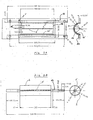
    1. Apparatus for applying adhesive or bonding material to tiles (3), especially flooring tiles, comprising a dispensing tank (1) containing a suitable adhesive (6), a tile magazine (4, 14) and a tile transfer mechanism (16,17; 21,22) assembled together on an supporting frame (20) of the apparatus which is preferably designed to be movable, characterized in that the apparatus is adapted to apply said adhesive in a continuous way to abonding surface of the tiles supplied automatically tile after tile from said tile magazine, in that the dispensing tank comprises a rotatable roll (2) for dispensing adhesive material through one or more bottom holes or slits (5) of said tank when a tile is horizontally displaced on guiding means (18) underneath and past said dispensing holes by transfer means (16; 22), and in that said dispensing roll is actuatable in selective synchronicity with the linear displacement of said tiles resp.transfer movement of said tile transfer means (16, 22).
    2. Apparatus according to claim 1, wherein said roll (2) comprises radially extending scraping elements (7), preferably elastic ribs fixed to the roll circumference in grooves thereof running parallel to the roll axis, said ribs aiding in dispensing adhesive through bottom holes (5).
    3. Apparatus according to claim 1 or 2, wherein the dispensing tank comprises a semi-cylindrical bottom part (9, 10) forming a housing for the dispensing roll (2), said bottom part including a plurality of dispensing holes or slits (5) located below said roll and arranged preferably in a row at the lowest line of said tank bottom semi-cylinder, whereby said roll is arranged so as to form an extrusion gap (8) between its circumference and a first tank bottom part (9) , but forming a sealing gap with a second wall part (10) of the tank bottom past the dispensing orifices (5).
    4. Apparatus according to claims 1 to 3, wherein said dispensing tank (1) is composed of two parts, namely a lower semi-cylindrical part (9, 10) fixedly attached to support bars (11) supported onto apparatus frame (20) and a detachable upper part (1') for containing said adhesive cement or paste (6) which is also attachable to support bars (11).
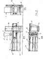
    5. Apparatus according to claim 1 , wherein the tile transfer means is selected from an endless belt (21) mounted below and/or between said tile guiding means (18), a hydraulic jack (16) or an electromechanical mechanism having an driven shaft element (16') with pusher or drawer bar (17) connected thereto for horizontal tile transfer, said tile transfer means being operatively coupled with said rotatable dispensing roll (2).
    6. Apparatus according to claims 1 or 5, wherein tile transfer and dispensing roll rotation is actuated by hydraulic power from an electro-hydraulic group mounted onto support frame (20), actuating the combination of preferably a hydraulic motor coupled to said dispensing roll for rotating the same and a hydraulic cylinder/piston unit (16,16') for tile transfer.
    7. Apparatus according to claim 1 or 7, wherein the tile magazine is configured as a hydraulic lift (14) which is movable and integratable with the apparatus, said hydraulic lift being capable of adjusting the upper tile of the supported/lifted tile stack into a desired tile transfer position for subsequent displacement and adhesive paste application.
    8. Apparatus according to claim 1, wherein the tile magazine (4) is mechanically fixed on frame (20) and is located in front of adhesive applicator (1, 2) but above tile guiding means (18), such that the lowest tile of the supported tile stack is enabled to be displaced by the tile transfer means to underneath the adhesive applicator unit, said tile magazine optionally including retractable means capable of bearing the stack weight pressing onto the lowest tile being brought into a tile transfer/coating position.
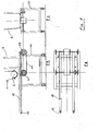
    9. Apparatus according to claim 1, wherein the tile displacement and transfer track (F2, F3) resp. tile guiding means (18) comprises a plurality of detecting elements or contact switches, capable of detecting a tile in any one of the different main locations along said track and responsive thereto being capable of establishing selective synchronous actuation of tile transfer means (16, 22) and rotation of dispenser roll (2) for applying adhesive to a tile being displaced underneath said roll towards a discharge position at the end of tile guides (18).
    10. Apparatus according to any one of claims 1 to 9, wherein there is provided along the tile displacement path (F2, F3) a number of contact switches adapted for tile location detection and selective actuation of said tile transfer means resp. of said adhesive applicator roll, said switches including at least a tile feed or start switch which actuates tile displacement towards the adhesive applicator, a tile discharge or end switch (19) which stops the apparatus if the coated last tile is not discharged in time from the tile guide , and further one or more dispenser switches positioned between start switch and discharge switch at a location close to the dispensing openings for selective actuation of the applicator roll, the latter switches allowing a tile surface to be coated over an adjustable length without spill-over of adhesive.
    11. Apparatus according to claim 8, wherein the tile magazine (4) is equipped with pneumatic means for transferring tile by tile from the magazine towards tile guiding means (18) and an endless conveyor belt (21) running underneath the tile magazine, said means preferably comprising two cooperating pneumatic devices, a first device for holding up a tile stack loaded in the magazine and a second device capable of supporting the tile stack, extracting tile by tile from the stack bottom and laying each tile on the tile guides (18) while the rest of the stack is kept up by the first device.
    EP05075022A 2004-01-08 2005-01-07 Tile coating apparatus for flooring Withdrawn EP1598502A3 (en)

    Priority Applications (1)

    Application Number Priority Date Filing Date Title
    EP05075022A EP1598502A3 (en) 2004-01-08 2005-01-07 Tile coating apparatus for flooring

    Applications Claiming Priority (3)

    Application Number Priority Date Filing Date Title
    EP04075056 2004-01-08
    EP04075056 2004-01-08
    EP05075022A EP1598502A3 (en) 2004-01-08 2005-01-07 Tile coating apparatus for flooring

    Publications (2)

    Publication Number Publication Date
    EP1598502A2 true EP1598502A2 (en) 2005-11-23
    EP1598502A3 EP1598502A3 (en) 2007-05-30

    Family

    ID=35126016

    Family Applications (1)

    Application Number Title Priority Date Filing Date
    EP05075022A Withdrawn EP1598502A3 (en) 2004-01-08 2005-01-07 Tile coating apparatus for flooring

    Country Status (1)

    Country Link
    EP (1) EP1598502A3 (en)

    Cited By (12)

    * Cited by examiner, † Cited by third party
    Publication number Priority date Publication date Assignee Title
    WO2007060537A3 (en) * 2005-11-25 2007-10-25 Gi Costruzioni Meccaniche S R A device for dispensing adhesive to planar surfaces, in particular tiles, an automatic machine for applying adhesive to planar surfaces and an adhesive cartridge
    CN107700813A (en) * 2017-08-30 2018-02-16 无为县鑫品石业有限公司 A kind of application device of circular Dali stone ceramic tile
    WO2018104334A1 (en) 2016-12-07 2018-06-14 Sika Technology Ag System and method for applying a tile adhesive
    CN108580196A (en) * 2018-07-10 2018-09-28 苏州柯谱瑞欣通信科技有限公司 A kind of computer CPU hardware thermal paste application device
    CN110761532A (en) * 2019-11-18 2020-02-07 苏州金螳螂建筑装饰股份有限公司 A fast ash-laying device for ceramic tiles
    CN111456393A (en) * 2020-04-10 2020-07-28 储高鹏 Indoor building decoration material ceramic tile laying construction process
    CN111760747A (en) * 2020-07-02 2020-10-13 广东博智林机器人有限公司 Ceramic tile gluing device, gluing method and paving equipment
    CN112850079A (en) * 2021-03-08 2021-05-28 重庆唯美陶瓷有限公司 Brick storage and arrangement equipment and brick storage and arrangement method
    CN113856987A (en) * 2021-09-17 2021-12-31 深圳市旭崇自动化设备有限公司 Glue joint line
    CN114082594A (en) * 2021-10-21 2022-02-25 深圳天丰泰科技股份有限公司 High-precision full-automatic high-speed visual dispenser
    CN114541695A (en) * 2021-12-23 2022-05-27 林德和 Ceramic tile back cement that building decoration used paints equipment
    CN115637838A (en) * 2022-11-17 2023-01-24 铜陵有色金属集团股份有限公司 Interior decoration ground waterproof layer coating device for building

    Family Cites Families (4)

    * Cited by examiner, † Cited by third party
    Publication number Priority date Publication date Assignee Title
    DE2538150A1 (en) * 1975-08-27 1977-03-10 Conver Machinebouw B V Beusich Machine for transport and formation of tiles - has endless belt conveyor on frame with openings through which side roll pressure is applied
    US4604966A (en) * 1985-10-10 1986-08-12 International Business Machine Corp. Continuous solder paste dispenser
    IT1262660B (en) * 1993-09-10 1996-07-04 T S C S R L DECORATING MACHINE - ROTARY GLAZING MACHINE FOR CERAMIC TILES.
    ITBO20010340A1 (en) * 2001-05-29 2002-11-29 Tecno Europa Srl UNIT FOR THE DECORATION OF CERAMIC PRODUCTS

    Cited By (18)

    * Cited by examiner, † Cited by third party
    Publication number Priority date Publication date Assignee Title
    WO2007060537A3 (en) * 2005-11-25 2007-10-25 Gi Costruzioni Meccaniche S R A device for dispensing adhesive to planar surfaces, in particular tiles, an automatic machine for applying adhesive to planar surfaces and an adhesive cartridge
    US10947743B2 (en) 2016-12-07 2021-03-16 Sika Technology Ag System and method for applying a tile adhesive
    CN109891036A (en) * 2016-12-07 2019-06-14 Sika技术股份公司 System and method for applying brick adhesive
    CN109891036B (en) * 2016-12-07 2022-08-09 Sika技术股份公司 System and method for applying a brick binder
    WO2018104334A1 (en) 2016-12-07 2018-06-14 Sika Technology Ag System and method for applying a tile adhesive
    CN107700813A (en) * 2017-08-30 2018-02-16 无为县鑫品石业有限公司 A kind of application device of circular Dali stone ceramic tile
    CN108580196A (en) * 2018-07-10 2018-09-28 苏州柯谱瑞欣通信科技有限公司 A kind of computer CPU hardware thermal paste application device
    CN110761532A (en) * 2019-11-18 2020-02-07 苏州金螳螂建筑装饰股份有限公司 A fast ash-laying device for ceramic tiles
    CN111456393B (en) * 2020-04-10 2021-06-18 李红军 Indoor building decoration material ceramic tile laying construction process
    CN111456393A (en) * 2020-04-10 2020-07-28 储高鹏 Indoor building decoration material ceramic tile laying construction process
    CN111760747A (en) * 2020-07-02 2020-10-13 广东博智林机器人有限公司 Ceramic tile gluing device, gluing method and paving equipment
    CN111760747B (en) * 2020-07-02 2022-07-12 广东博智林机器人有限公司 Ceramic tile gluing device, gluing method and paving equipment
    CN112850079A (en) * 2021-03-08 2021-05-28 重庆唯美陶瓷有限公司 Brick storage and arrangement equipment and brick storage and arrangement method
    CN113856987A (en) * 2021-09-17 2021-12-31 深圳市旭崇自动化设备有限公司 Glue joint line
    CN114082594A (en) * 2021-10-21 2022-02-25 深圳天丰泰科技股份有限公司 High-precision full-automatic high-speed visual dispenser
    CN114541695A (en) * 2021-12-23 2022-05-27 林德和 Ceramic tile back cement that building decoration used paints equipment
    CN114541695B (en) * 2021-12-23 2023-11-28 广州原点建设工程有限公司 Ceramic tile back cement of building decoration usefulness is paintd equipment
    CN115637838A (en) * 2022-11-17 2023-01-24 铜陵有色金属集团股份有限公司 Interior decoration ground waterproof layer coating device for building

    Also Published As

    Publication number Publication date
    EP1598502A3 (en) 2007-05-30

    Similar Documents

    Publication Publication Date Title
    EP1598502A2 (en) Tile coating apparatus for flooring
    CN111760747B (en) Ceramic tile gluing device, gluing method and paving equipment
    RU2374408C1 (en) Cherepanov's tile layer
    US4884958A (en) Apparatus for setting up and pouring concrete forms
    US4067766A (en) Automatic building block laying panel-forming machine and method
    CN112854695A (en) Intelligent brick paving equipment
    US10443250B2 (en) Method for continuously extruding and depositing an unbroken layer of mortar on a work surface or substrate
    US5035592A (en) Apparatus for concrete supply and form vibration
    US6125902A (en) Apparatus for applying an improved adhesive to sheet insulation having drainage channels
    CN112554507B (en) Auxiliary device for tiling indoor wall and tiling process
    CN110761569B (en) Brick concrete daubs device for construction
    EP1319445A2 (en) A machine for the automatic resinning of flat boards or parts for construction
    CN209618539U (en) A kind of PVC film laying apparatus for land protection
    JPH0633592A (en) Plate-like surface finishing material pasting equipment
    CN115106261B (en) External wall insulation board draws auxiliary assembly
    US9157246B2 (en) Method and apparatus for selectively extruding and applying a layer of mortar upon a selected surface
    DE19632844C1 (en) Application of thin bed mortar on underside of porous building block
    CN120306183A (en) A mechanized and efficient steel pipe paint dyeing device and method
    JPH0631715A (en) Plate-like surface finishing material pasting equipment
    CN113323342A (en) Equipment for paving and pasting ceramic tiles in building room
    PL201395B1 (en) Method of and apparatus for applying mortar
    CN110318523A (en) A kind of mixer for ground tile paving
    CN112982922B (en) A construction material unloading device and its use method
    CN113494173B (en) Leveling robot control method and leveling robot
    CN116768508B (en) Raw material preheating device for silicate cement wallboard production

    Legal Events

    Date Code Title Description
    PUAI Public reference made under article 153(3) epc to a published international application that has entered the european phase

    Free format text: ORIGINAL CODE: 0009012

    AK Designated contracting states

    Kind code of ref document: A2

    Designated state(s): AT BE BG CH CY CZ DE DK EE ES FI FR GB GR HU IE IS IT LI LT LU MC NL PL PT RO SE SI SK TR

    AX Request for extension of the european patent

    Extension state: AL BA HR LV MK YU

    PUAL Search report despatched

    Free format text: ORIGINAL CODE: 0009013

    AK Designated contracting states

    Kind code of ref document: A3

    Designated state(s): AT BE BG CH CY CZ DE DK EE ES FI FR GB GR HU IE IS IT LI LT LU MC NL PL PT RO SE SI SK TR

    AX Request for extension of the european patent

    Extension state: AL BA HR LV MK YU

    17P Request for examination filed

    Effective date: 20070809

    AKX Designation fees paid

    Designated state(s): AT BE BG CH CY CZ DE DK EE ES FI FR GB GR HU IE IS IT LI LT LU MC NL PL PT RO SE SI SK TR

    17Q First examination report despatched

    Effective date: 20110222

    GRAP Despatch of communication of intention to grant a patent

    Free format text: ORIGINAL CODE: EPIDOSNIGR1

    GRAS Grant fee paid

    Free format text: ORIGINAL CODE: EPIDOSNIGR3

    STAA Information on the status of an ep patent application or granted ep patent

    Free format text: STATUS: THE APPLICATION IS DEEMED TO BE WITHDRAWN

    18D Application deemed to be withdrawn

    Effective date: 20120727