EP1598306A1 - Vorrichtung zur Steuerung des Absenkens einer hydraulischen Hubvorrichtung - Google Patents
Vorrichtung zur Steuerung des Absenkens einer hydraulischen Hubvorrichtung Download PDFInfo
- Publication number
- EP1598306A1 EP1598306A1 EP05356081A EP05356081A EP1598306A1 EP 1598306 A1 EP1598306 A1 EP 1598306A1 EP 05356081 A EP05356081 A EP 05356081A EP 05356081 A EP05356081 A EP 05356081A EP 1598306 A1 EP1598306 A1 EP 1598306A1
- Authority
- EP
- European Patent Office
- Prior art keywords
- primary
- valve
- channel
- chamber
- hydraulic jack
- Prior art date
- Legal status (The legal status is an assumption and is not a legal conclusion. Google has not performed a legal analysis and makes no representation as to the accuracy of the status listed.)
- Withdrawn
Links
- 239000012530 fluid Substances 0.000 claims abstract description 33
- 230000006835 compression Effects 0.000 claims description 2
- 238000007906 compression Methods 0.000 claims description 2
- 230000005484 gravity Effects 0.000 description 4
- 241000282414 Homo sapiens Species 0.000 description 2
- 238000005553 drilling Methods 0.000 description 1
- 230000002349 favourable effect Effects 0.000 description 1
- 238000004519 manufacturing process Methods 0.000 description 1
- 238000005086 pumping Methods 0.000 description 1
- 230000000284 resting effect Effects 0.000 description 1
Images


Classifications
-
- B—PERFORMING OPERATIONS; TRANSPORTING
- B66—HOISTING; LIFTING; HAULING
- B66F—HOISTING, LIFTING, HAULING OR PUSHING, NOT OTHERWISE PROVIDED FOR, e.g. DEVICES WHICH APPLY A LIFTING OR PUSHING FORCE DIRECTLY TO THE SURFACE OF A LOAD
- B66F3/00—Devices, e.g. jacks, adapted for uninterrupted lifting of loads
- B66F3/24—Devices, e.g. jacks, adapted for uninterrupted lifting of loads fluid-pressure operated
- B66F3/25—Constructional features
- B66F3/42—Constructional features with self-contained pumps, e.g. actuated by hand
Definitions
- the present invention relates to a hydraulic jack allowing lifting heavy loads from the ground.
- a hydraulic jack is a well known lifting device and widely used to lift loads of several tons.
- a hydraulic jack usually includes a sole intended to come on a bearing surface, a column connected to the sole, a cylindrical shaft slidably mounted on the column and delimiting with it a chamber of a jack.
- the actuation of the jack is done by a pump provided with a valve sucking an incompressible fluid into a reservoir for feed the cylinder chamber.
- the pump is usually operated by a lever whose Alternative actions feed the chamber with fluid. This being incompressible, there is a relative movement of the shaft with respect to the column. Therefore, an object placed at the top of the drum or resting on a tab secured to the barrel is raised relative to the surface on which rest the jack.
- the pump flap is open and the fluid contained in the cylinder chamber is forced back into the tank.
- the universally used system consists of a button that he turn in one direction to open the flap and control the descent, and in the other direction to close the flap and stop the descent. This system works perfectly but it raises an important problem of security.
- the operator may be in the inability to turn the knob to stop the descent. It can thus be find stuck under the raised object, without being able to interrupt the descent jack.
- An object of the present invention is to propose a jack hydraulic system whose descent in charge is interrupted as soon as a operator stops his action on a descent control device and whose descent in the absence of charge is carried out under the action of the gravity.
- the jack comprises a control device including a small section primary canal, connecting the chamber to the tank, closed by a primary valve allowing the passage of fluid from the chamber to the reservoir, the primary channel presenting a dimension such that the primary valve can be opened under an action maximum of 15 to 20 daN to oppose the pressure exerted by the fluid on the primary valve when the jack supports a charge and a secondary channel connecting the chamber to the closed tank by a secondary valve allowing the passage of fluid from the chamber to the tank, the secondary channel having a section allowing the drum to descend under its own weight when the secondary valve is open.
- the idea underlying the invention is to provide in the jack a primary channel of small diameter between the tank and the chamber; this primary channel is closed by a primary valve allowing the flow of the fluid between the chamber and the reservoir by opposing the flow in sense opposite.
- This primary valve is normally pressed against its seat by the pressurized fluid contained in the chamber. It should be noted that the fluid contained in the chamber is subjected to very high pressures up to 300 bar when the jack is loaded. Despite of this very strong pressure exerted on the valve closing the channel of small diameter, it is possible with a moderate action of about 15 daN, ie the average strength that an operator is able to exert manually, open this primary valve.
- the invention also makes it possible to solve the problem that may occur produce when the jack is in a configuration in which the chamber is filled with fluid (in other words, the jack is in the extended position), an action on the primary valve does not make it possible to lower the no load applied to the jack. It turns out that it counts given the small size of the primary canal connecting the chamber to the reservoir when it is opened by the valve, the jack has not come back down under the action of gravity.
- the secondary channel which is section important, allows to create a leakage flow, ensuring the descent of the jack on the sole action of gravity.
- the primary canal and the secondary channel are co-axial, the primary valve and the secondary valve being arranged one behind the other and actuated by the same button button.
- the primary valve is constituted by a ball closing the primary channel and the secondary valve is constituted by a ring in which is formed the primary channel, the ring from closing the secondary channel.
- the device for control includes a cartridge embedded in a housing, arranged on the body of the pump and connected to the chamber and the receiving tank the primary valve and the secondary valve.
- the cartridge has a longitudinal bore forming the secondary channel in which the rod is engaged, the piercing having a shoulder forming a seat of the secondary valve.
- the hole is closed by a plug against which two coaxial compression springs, one applying against the ring, the other applying against the ball.
- the block has at least one radial channel opening in the secondary channel.
- the primary channel has a diameter of between 1 and 2.5 millimeters.
- the primary channel has a diameter of 1.2 millimeters.
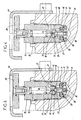
- the jack as shown in Figure 2, includes a sole 2, a column 3 connected to the sole 2 and a cylindrical shaft 4 mounted sliding on the column 3 and delimiting with it a chamber 5.
- the jack is, in addition, equipped with a pump 6 capable of sucking a fluid incompressible contained in a reservoir 8 and to repress this fluid in the
- the pumping of the fluid is done by means of a lever 9 whose movements can push back to the chamber, the fluid incompressible through an anti-return valve. 10.
- the Jack has a very classic structure.
- the jack according to the invention differs from the jacks as they exist thanks to a device allowing to lower the barrel by a so-called command of the dead man.
- FIG. 1 it can be seen that a housing 11 is placed above the pump.
- Figure 3 shows a section of the device integrated in this housing 11.
- this housing 11 has a hole 13 one blind connected to the tank 8 and to the chamber 5.
- a tubular cartridge 15 is engaged in the bore 13; the tubular cartridge 1 5 bears against a shoulder 16 of the piercing to separate a compartment 17 located on the side of the tank and a compartment 18 located on the cylinder side.
- the device comprises two valves arranged in series, namely a primary valve I and a secondary valve II respectively closing a primary channel 20 and a secondary channel 21.
- the housing has a blind drilling connected to the tank and the cylinder.
- a tubular cartridge 15 is engaged in the bore 13, the cartridge has a chamfer that bears against a shoulder 16 so as to separate, in a sealed manner, a zone 17 connected to the jack and an area 18 connected to the tank.
- the cartridge 15 has a hole that constitutes the channel secondary 21 and a second bore of larger diameter connected to the first by a shoulder 24.
- the secondary valve II is formed by a ring 25 which comes into bearing against the shoulder 24 and thus closes the secondary channel 21.
- the primary valve I is, in turn, constituted by a ball 27 which closes a hole made in the ring forming the channel 20.
- the primary channel 20 has a very small diameter of the order of 1.2 millimeters.
- a plug 28 holds a spring 30 which holds the ball 27 of the primary valve I against its seat and a spring 29 which holds the ring 25 of the secondary valve II against its seat.
- a pilot rod 32 is engaged in the secondary channel 21.
- This pilot rod 32 is equipped with a finger 34 can enter the primary channel 20 and has, moreover, a radial bearing surface 36 able to bear on the ring 25.
- the pilot rod 32 has a diameter substantially equal to that of the secondary channel 21 and can slide in the latter.
- the cartridge has two channels 37 Radials providing a connection to the tank 8.
- the pilot rod 32 is equipped with a protected pusher 39 by a cowling 40.
- the operation of the jack is therefore the following.
- the jack is implemented in a very classic way in actuating the lever 9 to discharge the incompressible fluid into the chamber 5 and move the barrel 4 relative to the column to lift a load that located either at a support leg 42 or directly on the upper surface of the drum 4.
- this primary valve I it is possible with an action of about 15 to 20 daN, ie the action manual of an operator to open the primary flap I by taking off the ball 27 from his seat. This allows leakage of the fluid contained in the chamber 5.
- the fluid contained in the chamber 5 escapes to the tank 8 through exhaust channels 37, for this purpose, in the cartridge 15.
- the primary valve I closing the primary channel 20 of small section it is possible to realize a descent control device a loaded jack that stops as soon as an action stops on it.
- the primary valve I provides an insufficient leakage rate.
- the barrel does not descend under his action of gravity.
- the pilot rod 32 bears on the ring 25 and thus opens the secondary valve II. Fluid does not exert pressure on the valve secondary II since the jack is without load.
- the secondary valve II can then fade, there occurs a high leakage rate through the secondary channel 21 which is of a section much higher than that of the primary channel 20. This leakage flow important allows the jack to go down even when empty.
- the invention therefore provides a jack presenting a control of descent by a dead man type pusher, since when the jack is in charge, stopping an action on this device leads to an interruption of the jack's descent.
- this device can be adapted to any type of jack hydraulic.
Landscapes
- Life Sciences & Earth Sciences (AREA)
- Engineering & Computer Science (AREA)
- Geology (AREA)
- Mechanical Engineering (AREA)
- Structural Engineering (AREA)
- Accommodation For Nursing Or Treatment Tables (AREA)
- Fluid-Pressure Circuits (AREA)
Applications Claiming Priority (2)
| Application Number | Priority Date | Filing Date | Title |
|---|---|---|---|
| FR0405412 | 2004-05-18 | ||
| FR0405412A FR2870533B1 (fr) | 2004-05-18 | 2004-05-18 | Dispositif de commande de descente d'un cric hydraulique |
Publications (1)
| Publication Number | Publication Date |
|---|---|
| EP1598306A1 true EP1598306A1 (de) | 2005-11-23 |
Family
ID=34942707
Family Applications (1)
| Application Number | Title | Priority Date | Filing Date |
|---|---|---|---|
| EP05356081A Withdrawn EP1598306A1 (de) | 2004-05-18 | 2005-05-17 | Vorrichtung zur Steuerung des Absenkens einer hydraulischen Hubvorrichtung |
Country Status (2)
| Country | Link |
|---|---|
| EP (1) | EP1598306A1 (de) |
| FR (1) | FR2870533B1 (de) |
Cited By (1)
| Publication number | Priority date | Publication date | Assignee | Title |
|---|---|---|---|---|
| EP3741505A1 (de) * | 2019-05-13 | 2020-11-25 | Automatisation et Controle du Serrage | Autonome palette |
Citations (5)
| Publication number | Priority date | Publication date | Assignee | Title |
|---|---|---|---|---|
| FR810986A (fr) * | 1935-12-19 | 1937-04-03 | Metivier Lang & Cie | Perfectionnements au dispositif de descente pour crics hydrauliques |
| US2352390A (en) * | 1943-05-13 | 1944-06-27 | Everett R Kirkland | Hydraulic jack |
| US2863285A (en) * | 1957-02-15 | 1958-12-09 | Timothy C Pomeroy | Hydraulic jack |
| US4886244A (en) * | 1987-06-22 | 1989-12-12 | Jacques Renault | Hydraulic lift perfected for the lifting and the handling of heavy loads of several tons |
| US5775672A (en) * | 1997-02-21 | 1998-07-07 | Hsu; Kun-Shan | Release valve for lifting devices |
-
2004
- 2004-05-18 FR FR0405412A patent/FR2870533B1/fr not_active Expired - Fee Related
-
2005
- 2005-05-17 EP EP05356081A patent/EP1598306A1/de not_active Withdrawn
Patent Citations (5)
| Publication number | Priority date | Publication date | Assignee | Title |
|---|---|---|---|---|
| FR810986A (fr) * | 1935-12-19 | 1937-04-03 | Metivier Lang & Cie | Perfectionnements au dispositif de descente pour crics hydrauliques |
| US2352390A (en) * | 1943-05-13 | 1944-06-27 | Everett R Kirkland | Hydraulic jack |
| US2863285A (en) * | 1957-02-15 | 1958-12-09 | Timothy C Pomeroy | Hydraulic jack |
| US4886244A (en) * | 1987-06-22 | 1989-12-12 | Jacques Renault | Hydraulic lift perfected for the lifting and the handling of heavy loads of several tons |
| US5775672A (en) * | 1997-02-21 | 1998-07-07 | Hsu; Kun-Shan | Release valve for lifting devices |
Cited By (1)
| Publication number | Priority date | Publication date | Assignee | Title |
|---|---|---|---|---|
| EP3741505A1 (de) * | 2019-05-13 | 2020-11-25 | Automatisation et Controle du Serrage | Autonome palette |
Also Published As
| Publication number | Publication date |
|---|---|
| FR2870533B1 (fr) | 2007-10-12 |
| FR2870533A1 (fr) | 2005-11-25 |
Similar Documents
| Publication | Publication Date | Title |
|---|---|---|
| EP0935715B1 (de) | Haltevorrichtung einer hydraulischen arbeitszylinderstange | |
| FR2518694A1 (fr) | Vanne de non-retour a commande hydraulique, notamment pour dispositif de commande de remise en position pour soutenement a etancons hydrauliques | |
| FR2460435A1 (fr) | Distributeur hydraulique, destine notamment a equiper des servo-commandes d'avions et d'helicopteres | |
| EP1931959B1 (de) | Fluidströmungs-steuerventil | |
| EP3212362B1 (de) | Schlagvorrichtung | |
| EP0046788B1 (de) | Hydraulischer pressenmechanismus | |
| FR2955572A1 (fr) | Dispositif de remplissage d'un reservoir par gravite ou sous pression | |
| FR2986848A1 (fr) | Soupape de surpression pour outil de presse hydraulique, et outil de presse hydraulique associe | |
| FR2475739A1 (fr) | Soupape de detection de deceleration | |
| FR2995370A1 (fr) | Soupape de chambre accumulatrice a commande hydraulique de systeme de freinage de vehicule | |
| EP1598306A1 (de) | Vorrichtung zur Steuerung des Absenkens einer hydraulischen Hubvorrichtung | |
| FR3044572A1 (fr) | Dispositif brise roches | |
| EP3072676A1 (de) | Gesicherte gasfedervorrichtung | |
| WO2013041585A1 (fr) | Dispositif d'echappement controle associe a un dispositif de distribution sous pression de liquide dans un recipient | |
| EP2383456A1 (de) | Einfach wirkender Hydraulikzylinder | |
| EP3611389B1 (de) | Lineares stellglied mit verriegelung und verriegelungsanzeige | |
| EP3511476B1 (de) | Drückspüler für wasserklosetts mit drucktasten für die betätigung von grösseren und kleineren spülmengen | |
| FR2576966A1 (fr) | Ensemble de securite annulaire pour puits petrolier, en particulier a double zone de production | |
| EP0833013B1 (de) | Vorrichtung zur hydraulischen Kontrolle eines Hebezylinders eines Ladearms eines landwirtschaftlichen Fahrzeugs | |
| FR2465110A1 (fr) | Verin a simple effet, a verrouillage hydraulique de position | |
| EP1375807B1 (de) | Türschliesser mit hydraulischer Dämpfung | |
| FR2892093A1 (fr) | Installation pour le remplissage de recipient, en particulier de recipient aerosol | |
| FR2528146A1 (fr) | Valve magnetique pilotee a systeme d'obturation perfectionne | |
| FR2595783A1 (fr) | Robinet temporise avec fermeture automatique du clapetÿa | |
| FR2888228A1 (fr) | Dispositif de securite d'un cric hydraulique |
Legal Events
| Date | Code | Title | Description |
|---|---|---|---|
| PUAI | Public reference made under article 153(3) epc to a published international application that has entered the european phase |
Free format text: ORIGINAL CODE: 0009012 |
|
| AK | Designated contracting states |
Kind code of ref document: A1 Designated state(s): AT BE BG CH CY CZ DE DK EE ES FI FR GB GR HU IE IS IT LI LT LU MC NL PL PT RO SE SI SK TR |
|
| AX | Request for extension of the european patent |
Extension state: AL BA HR LV MK YU |
|
| 17P | Request for examination filed |
Effective date: 20060515 |
|
| AKX | Designation fees paid |
Designated state(s): AT BE BG CH CY CZ DE DK EE ES FI FR GB GR HU IE IS IT LI LT LU MC NL PL PT RO SE SI SK TR |
|
| 17Q | First examination report despatched |
Effective date: 20080704 |
|
| GRAP | Despatch of communication of intention to grant a patent |
Free format text: ORIGINAL CODE: EPIDOSNIGR1 |
|
| STAA | Information on the status of an ep patent application or granted ep patent |
Free format text: STATUS: THE APPLICATION IS DEEMED TO BE WITHDRAWN |
|
| 18D | Application deemed to be withdrawn |
Effective date: 20090730 |