EP1598213B1 - Lockable fast adjustable compass - Google Patents
Lockable fast adjustable compass Download PDFInfo
- Publication number
- EP1598213B1 EP1598213B1 EP05010057.7A EP05010057A EP1598213B1 EP 1598213 B1 EP1598213 B1 EP 1598213B1 EP 05010057 A EP05010057 A EP 05010057A EP 1598213 B1 EP1598213 B1 EP 1598213B1
- Authority
- EP
- European Patent Office
- Prior art keywords
- threaded
- compass
- adjusting spindle
- adjustment
- spindle
- Prior art date
- Legal status (The legal status is an assumption and is not a legal conclusion. Google has not performed a legal analysis and makes no representation as to the accuracy of the status listed.)
- Active
Links
- 230000000903 blocking effect Effects 0.000 claims description 21
- 229920003023 plastic Polymers 0.000 claims description 4
- 239000004033 plastic Substances 0.000 claims description 4
- 239000000463 material Substances 0.000 claims 1
- 238000010276 construction Methods 0.000 description 2
- 238000006073 displacement reaction Methods 0.000 description 1
- 230000000694 effects Effects 0.000 description 1
- 238000012986 modification Methods 0.000 description 1
- 230000004048 modification Effects 0.000 description 1
- 230000000149 penetrating effect Effects 0.000 description 1
Images

Classifications
-
- B—PERFORMING OPERATIONS; TRANSPORTING
- B43—WRITING OR DRAWING IMPLEMENTS; BUREAU ACCESSORIES
- B43L—ARTICLES FOR WRITING OR DRAWING UPON; WRITING OR DRAWING AIDS; ACCESSORIES FOR WRITING OR DRAWING
- B43L9/00—Circular curve-drawing or like instruments
- B43L9/16—Features common to compasses, dividers, and callipers
- B43L9/22—Leg-angle adjusting-means separate from pivots
Definitions
- the invention relates to a Schnellverstellzirkel with a circular limbs in it threaded sleeves passing through threaded adjusting spindle with a centrally disposed, non-rotatably connected to the threaded adjusting spindle adjustment.
- a compass is known in which on one side of a hole through which an adjusting spindle is guided, a female thread is attached. By pressing a button, the adjusting spindle can be moved within the hole, so that it can move freely without entrainment or can be finely adjusted using an adjusting wheel.
- the invention is therefore based on the object, a Schnellverstellzirkel of the type mentioned in such a way that with a simple construction a complete play-free blocking of the threaded adjusting spindle in any pivot position of Schnellverstellzirkels is possible.
- the invention provides that the threaded adjusting spindle is designed to run along and at least one locking pin at least partially penetrating locking screw or by at least one cap nut in the threaded sleeves is blocked, the threaded adjusting spindle by the locking screw or the cap nut with her Thread can be pressed directly to a blocking member.
- a first embodiment of this solution according to the invention in which the threaded sleeve is not clamped for detecting the threaded adjusting spindle, provides for this purpose that the threaded sleeve in a perpendicular to the axis of the threaded adjusting spindle through recess of the compass leg slidably mounted bolt with cross-threaded holes for is the threaded adjusting spindle, which is adjustable by a screwed onto an end male threaded portion cap nut under tensioning the threaded adjusting spindle on the acting as a blocking member inner wall of the interspersed by her breakthrough of the compass leg.
- the locking screw or the cap nut presses a threaded sleeve transverse to the threaded bore for the threaded adjusting spindle, designed as blocking member blocking pin in the thread of the threaded adjusting spindle.
- the blocking pin can preferably be formed of plastic, so that damage to the thread of the threaded adjusting spindle can not take place, leads in a particularly simple manner to an exact play-free blocking of the threaded adjusting spindle.
- the training is similar in this second variant of the solution with bound on the compass legs threaded adjusting spindle, although here the threaded adjusting spindle is not blocked by jamming to the compass legs, but by the sliding in the hollow bolt of the threaded sleeve on the locking cap nut locking pin.
- Fig. 4 discloses an unclaimed embodiment wherein the threaded sleeve does not push a locking pin into the thread of the threaded adjusting spindle.
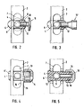
- Fig. 1 can be seen a Schnellverstellzirkel with two pivotally mounted on a head part 1 compass legs 2 and 3, which are penetrated by a threaded adjusting spindle 4 with adjusting 5, wherein the threaded adjusting 4 in a different way formable threaded sleeves, with 6 in Fig. 2 referred to, interspersed, which are mounted transversely to the axis of the threaded adjusting spindle 4 openings of the compass legs 2, 3.
- locking devices are arranged on each of the compass legs 2, 3, although it would of course be sufficient for the operation, if only one of the legs would be provided with such a locking device.
- the simplest form of locking the threaded adjusting spindle 4 and thus the determination of Schnellverstellzirkels in a desired pivot position is in Fig. 2 shown.
- the threaded sleeve 6 forms there in the perpendicular to the axis of the threaded adjusting spindle 4 through recess 8 mounted bolt with a threaded hole 9 for the threaded adjusting spindle 4, in which a transverse threaded bore 10 opens, in which a locking screw 11th can be screwed.
- the shank 12 of this locking screw 11 engages when screwing directly to the external thread of the threaded adjusting spindle 4 and blocks it and thus the compass in the desired position.
- the Fig. 3 shows a modification that differs from the Fig. 2 only differs in that it is the locking screw 11 'is a plastic screw, which has the advantage that when blocking the most metallic threaded adjusting spindle 4 whose external thread is not pushed by the locking screw, as in the metallic locking screw 11 after Fig. 2 the case could be.
- Fig. 4 In the arrangement according to Fig. 4 is the threaded sleeve 6 'for the threaded adjusting spindle forming bolts in the same way in the compass leg 2 (and possibly also 3) mounted, wherein the bolt is provided on the right side with an external thread 13 to which a cap nut 14 is screwed with internal thread , As soon as this cap nut 14 bears against the side 15 of the circular leg 2, it pulls the bolt to the right during further rotation and thus presses the threaded adjusting spindle 4 against an inner side 16 of the opening 7, so that in turn blocking of the threaded adjusting spindle 4 is achieved.
- the bolt forming the threaded sleeve 6 "is in turn provided with an external thread 13 for a cap nut 14, but this serves for displacing a pin 18 in an internal bore 19
- the pin 18, preferably a plastic pin for protecting the external thread of the threaded adjusting spindle 4 is pressed to the left against the threaded adjusting spindle 4 and blocks it in the respective position.
Description
Die Erfindung bezieht sich auf einen Schnellverstellzirkel mit einer die Zirkelschenkel in darin gelagerten Gewindehülsen durchsetzenden Gewinde-Verstellspindel mit einem mittig angeordneten, drehfest mit der Gewinde-Verstellspindel verbundenen Verstellrad.The invention relates to a Schnellverstellzirkel with a circular limbs in it threaded sleeves passing through threaded adjusting spindle with a centrally disposed, non-rotatably connected to the threaded adjusting spindle adjustment.
Ein herkömmlicher, nicht schnell verstellbarer Zirkel zeichnet sich dadurch aus, dass zwischen der Verstellspindel und dem in der Gewindehülse angebrachten Muttergewinde bei Druck gegen die Schenkel eine Selbsthemmung auftritt. Das bedeutet, dass eine Verstellung des Zirkels nur über eine Feinverstellung mit Hilfe des Verstellrades möglich ist. Diese Verstellung ist bei größeren Verstellstrecken jedoch entsprechend aufwändig.A conventional, not quickly adjustable compass is characterized in that between the adjusting spindle and the nut thread mounted in the threaded sleeve when pressure against the legs self-locking occurs. This means that an adjustment of the compass is only possible via a fine adjustment with the aid of the adjusting wheel. However, this adjustment is correspondingly expensive for larger adjustment distances.
Aus der Druckschrift
In der deutschen Auslegeschrift
Zur Herstellung solcher Schnellverstellzirkel ist beispielsweise bereits vorgeschlagen worden, die Gewindehülsen in einer durch die Achse der Verstellspindel gehenden Ebene zu teilen, wobei diese Teile durch eine Feststellschraube indirekt unter Zwischenordnung von Schwenkplatten gegeneinander verspannbar sind. Dies bedingt aber ein außerordentlich festes Anziehen der Verstellschraube und führt in vielen Fällen zwar zu einer Bremswirkung, aber nicht zu einer exakten Feststellung.For example, in order to produce such quick-adjustment calipers, it has already been proposed to split the threaded sleeves in a plane passing through the axis of the adjusting spindle, wherein these parts can be braced against one another indirectly by a locking screw with interposition of pivoting plates. However, this requires an extremely tight tightening the adjusting screw and in many cases leads to a braking effect, but not to a precise statement.
Darüber hinaus ist aber auch bereits eine Anordnung bekannt geworden, bei der aus dem Zirkelschenkel herausragende Enden der Gewindehülsen geschlitzt und mit konischen Außenflächen versehen sind, auf die entsprechende Gegenkonushülsen verschiebbar sind, die in der einen Stellung den Gewindehülsenkonus freigeben, sodass ein freies Verdrehen der Verstellspindel möglich ist und in der anderen Stellung den geschlitzten Gewindehülsenkonus zusammendrücken um auf diese Weise die Verstellspindel zu blockieren. Diese Lösung ist nicht nur sehr aufwändig, sondern hat, wie die bereits angesprochene Konstruktion, den Nachteil, dass ein völliges spielfreies Blockieren der Verstellspindel und damit der gewünschten Stellung des Schnellverstellzirkels nicht erzielbar ist.In addition, however, an arrangement has become known in which slotted out of the compass legs protruding ends of the threaded sleeves and are provided with conical outer surfaces are displaceable on the corresponding counter-cone, which release the threaded sleeve in one position, so that a free rotation of the adjusting spindle is possible and compress in the other position, the slotted threaded sleeve cone in order to block the adjusting spindle in this way. This solution is not only very complex, but has, as the already mentioned construction, the disadvantage that a complete backlash blocking the adjusting spindle and thus the desired position of the Schnellverstellzirkels is not achievable.
Der Erfindung liegt damit die Aufgabe zugrunde, einen Schnellverstellzirkel der eingangs genannten Art so auszugestalten, dass bei einfachem Aufbau ein völliges spielfreies Blockieren der Gewinde-Verstellspindel in jeder beliebigen Schwenkstellung des Schnellverstellzirkels möglich ist.The invention is therefore based on the object, a Schnellverstellzirkel of the type mentioned in such a way that with a simple construction a complete play-free blocking of the threaded adjusting spindle in any pivot position of Schnellverstellzirkels is possible.
Zur Lösung dieser Aufgabe ist erfindungsgemäß vorgesehen, dass die Gewinde-Verstellspindel mitlaufend ausgebildet ist und mittels wenigstens einer einen Zirkelschenkel zumindest teilweise durchsetzenden Feststellschraube oder mittels wenigstens einer Hutmutter in den Gewindehülsen blockierbar ist, wobei die Gewinde-Verstellspindel durch die Feststellschraube oder die Hutmutter mit ihrem Gewinde direkt an ein Blockierglied anpressbar ist.To solve this problem, the invention provides that the threaded adjusting spindle is designed to run along and at least one locking pin at least partially penetrating locking screw or by at least one cap nut in the threaded sleeves is blocked, the threaded adjusting spindle by the locking screw or the cap nut with her Thread can be pressed directly to a blocking member.
Eine erste Ausführungsform dieser erfindungsgemäßen Lösung, bei der nicht die Gewindehülse zum Feststellen der Gewinde-Verstellspindel verspannt wird, sieht zu diesem Zweck vor, dass die Gewindehülse ein in einer senkrecht zur Achse der Gewinde-Verstellspindel durchgehenden Ausnehmung des Zirkelschenkels verschiebbar gelagerter Bolzen mit Quergewindebohrungen für die Gewinde-Verstellspindel ist, der durch eine auf einen endseitigen Außengewindeabschnitt aufschraubbare Hutmutter unter Verspannen der Gewinde-Verstellspindel an der als Blockierglied wirkenden Innenwand des von ihr durchsetzten Querdurchbruchs des Zirkelschenkels verstellbar ist.A first embodiment of this solution according to the invention, in which the threaded sleeve is not clamped for detecting the threaded adjusting spindle, provides for this purpose that the threaded sleeve in a perpendicular to the axis of the threaded adjusting spindle through recess of the compass leg slidably mounted bolt with cross-threaded holes for is the threaded adjusting spindle, which is adjustable by a screwed onto an end male threaded portion cap nut under tensioning the threaded adjusting spindle on the acting as a blocking member inner wall of the interspersed by her breakthrough of the compass leg.
Bei dieser Lösung wird also durch die Feststellschraube der Bolzen mit der Gewinde-Verstellspindel quer zu der Längsachse seitlich verschoben, sodass sich die Gewinde-Verstellspindel mit ihrem Außengewinde unmittelbar an die Innenwand des Querdurchbruchs des Zirkelschenkels anlegt und auf diese Art und Weise blockiert wird. Bei dieser Ausführungsform bildet also die Innenwand des Querdurchbruchs des Zirkelschenkels das Blockierglied für die Gewinde-Verstellspindel.In this solution, the bolt with the threaded adjusting spindle is thus laterally displaced transversely to the longitudinal axis by the locking screw, so that the threaded adjusting spindle with its external thread directly applies to the inner wall of the transverse breakthrough of the compass leg and is blocked in this manner. In this embodiment, therefore, forms the inner wall of the transverse breakthrough of the compass leg, the blocking member for the threaded adjusting spindle.
Gemäß einer zweiten Ausführungsform der erfindungsgemäßen Lösung mit einem gesonderten Blockierglied ist vorgesehen, dass die Feststellschraube oder die Hutmutter einen die Gewindehülse quer zur Gewindebohrung für die Gewinde-Verstellspindel durchsetzenden, als Blockierglied ausgebildeten Blockierstift in das Gewinde der Gewinde-Verstellspindel drückt. Diese Lösung, bei der der Blockierstift bevorzugt aus Kunststoff ausgebildet sein kann, sodass eine Beschädigung des Gewindes der Gewinde-Verstellspindel nicht stattfinden kann, führt in ganz besonders einfacher Weise zu einer exakten spielfreien Blockierung der Gewinde-Verstellspindel.According to a second embodiment of the inventive solution with a separate blocking member is provided that the locking screw or the cap nut presses a threaded sleeve transverse to the threaded bore for the threaded adjusting spindle, designed as blocking member blocking pin in the thread of the threaded adjusting spindle. This solution, in which the blocking pin can preferably be formed of plastic, so that damage to the thread of the threaded adjusting spindle can not take place, leads in a particularly simple manner to an exact play-free blocking of the threaded adjusting spindle.
In Weiterbildung dieses zweiten Ausführungsbeispiels der Erfindung kann entweder vorgesehen sein, dass der Blockierstift der Gewindestift der Feststellschraube ist, die in eine Quergewindebohrung der Gewindehülse oder des Zirkelschenkels einschraubbar ist oder aber dass die Gewindehülse ein in einer senkrecht zur Achse der Gewinde-Verstellspindel durchgehenden Ausnehmung des Zirkelschenkels gelagerter Bolzen mit einem hohlen Schaft mit einer Innenbohrung ist, der auf einer Seite sich mit einem Bund am Zirkelschenkel abstützt, auf dessen herausstehendem anderen, mit einem Außengewinde versehenen Ende die Hutmutter unter Verschiebung des Blockierstifts in der Innenbohrung des Schaftes aufschraubbar ist.In a further development of this second embodiment of the invention can either be provided that the blocking pin is the set screw of the locking screw which is screwed into a transverse threaded bore of the threaded sleeve or the compass leg or that the threaded sleeve in a direction perpendicular to the axis of the threaded adjusting spindle recess of the Zirkelschenkels mounted bolt with a hollow shaft with an inner bore which is supported on one side with a collar on the compass legs, on the protruding other end provided with an external thread, the cap nut with displacement of the locking pin in the inner bore of the shaft is screwed.
Die Ausbildung ist bei dieser zweiten Variante ähnlich der Lösung mit am Zirkelschenkel verklemmter Gewinde-Verstellspindel, wobei allerdings hier die Gewinde-Verstellspindel nicht durch Verklemmen an den Zirkelschenkel blockiert wird, sondern durch den im hohlen Bolzen der Gewindehülse über die Feststell-Hutmutter verschiebbaren Blockierstift.The training is similar in this second variant of the solution with bound on the compass legs threaded adjusting spindle, although here the threaded adjusting spindle is not blocked by jamming to the compass legs, but by the sliding in the hollow bolt of the threaded sleeve on the locking cap nut locking pin.
Weitere Vorteile und Einzelheiten der Erfindung ergeben sich aus der nachfolgenden Beschreibung eines Ausführungsbeispiels sowie anhand der Zeichnung. Dabei zeigen:
- Fig. 1
- eine Ansicht eines Schnellverstellzirkels mit durch Feststellschrauben blockierbarer Gewinde-Verstellspindel, und
- Fig. 2 bis 5
- vergrößerte teilweise aufgeschnittene Teilseitenansichten des Zirkelschenkels in Höhe der Gewinde-Verstellspindel in Richtung des Pfeils P in
Fig. 1 .
- Fig. 1
- a view of a Schnellverstellzirkels with lockable by locking screws threaded adjusting spindle, and
- Fig. 2 to 5
- enlarged partially cutaway partial side views of the compass leg in height of the threaded adjusting spindle in the direction of arrow P in
Fig. 1 ,
In
Im gezeigten Ausführungsbeispiel sind an jedem der Zirkelschenkel 2, 3 Feststelleinrichtungen angeordnet, obgleich es für die Funktionsweise natürlich ausreichend wäre, wenn nur einer der Schenkel mit einer solchen Feststelleinrichtung versehen wäre. Die einfachste Form der Blockierung der Gewinde-Verstellspindel 4 und damit der Feststellung des Schnellverstellzirkels in einer gewünschten Schwenkposition ist in
Die
Bei der Anordnung nach
Beim Ausführungsbeispiel nach
Claims (3)
- Quick-adjustment compass having a threaded adjustment spindle (4), which passes through the compass arms (2, 3) in threaded sleeves (6', 6") mounted therein, and having a centrally arranged adjustment wheel (5), which is connected in a rotationally fixed manner to the threaded adjustment spindle (4), characterized in that the threaded adjustment spindle (4) is designed to accompany the movement of the compass and can be blocked in the threaded sleeves (6', 6") by means of at least one locking screw (11, 11'), which passes through a compass arm (2, 3) at least in part, or by means of at least one cap nut (14), wherein the threaded adjustment spindle (4) can have its thread pushed directly onto a blocking member (12, 18) by way of the locking screw (11, 11') or the cap nut (14), wherein a blocking pin (12) which passes through the threaded sleeve (6) in a direction transverse to the threaded bore (9) for the threaded adjustment spindle (4), and is designed in the form of a blocking member, is pushed into the thread of the threaded adjustment spindle (4) by the locking screw (11, 11'), the blocking pin (12) being the threaded pin of the locking screw (11, 11'), which can be screwed into a transversely threaded bore (10) of the threaded sleeve (6), or a blocking pin (18) which passes through the threaded sleeve (6") in a direction transverse to the threaded bore (9) for the threaded adjustment spindle (4), and is designed in the form of a blocking member, is pushed into the thread of the threaded adjustment spindle (4) by the cap nut (14).
- Quick-adjustment compass according to Claim 1, characterized in that the blocking pin (18) consists of plastics material.
- Quick-adjustment compass according to Claim 1 or 2, characterized in that the threaded adjustment spindle (4) can be pushed onto a blocking member in the two compass arms (2, 3).
Applications Claiming Priority (2)
| Application Number | Priority Date | Filing Date | Title |
|---|---|---|---|
| DE102004024945 | 2004-05-21 | ||
| DE200410024945 DE102004024945B4 (en) | 2004-05-21 | 2004-05-21 | Lockable quick-release compass |
Publications (3)
| Publication Number | Publication Date |
|---|---|
| EP1598213A2 EP1598213A2 (en) | 2005-11-23 |
| EP1598213A3 EP1598213A3 (en) | 2009-09-02 |
| EP1598213B1 true EP1598213B1 (en) | 2015-07-01 |
Family
ID=34936298
Family Applications (1)
| Application Number | Title | Priority Date | Filing Date |
|---|---|---|---|
| EP05010057.7A Active EP1598213B1 (en) | 2004-05-21 | 2005-05-09 | Lockable fast adjustable compass |
Country Status (2)
| Country | Link |
|---|---|
| EP (1) | EP1598213B1 (en) |
| DE (1) | DE102004024945B4 (en) |
Families Citing this family (1)
| Publication number | Priority date | Publication date | Assignee | Title |
|---|---|---|---|---|
| WO2012035562A2 (en) * | 2010-09-18 | 2012-03-22 | Chetan Jayendra Budh | Locking mechanism for drawing compass |
Family Cites Families (7)
| Publication number | Priority date | Publication date | Assignee | Title |
|---|---|---|---|---|
| DE176441C (en) * | ||||
| US2567733A (en) * | 1948-06-11 | 1951-09-11 | George A Ryan | Drawing compass attachment |
| GB722242A (en) * | 1952-11-12 | 1955-01-19 | Thornton Ltd Ag | Improvements in or relating to mathematical drawing instruments |
| DE1761101C2 (en) * | 1968-04-03 | 1974-04-25 | Guenther Partes Kg Reisszeugfabrik, 8535 Brunn | Compass with quick and fine adjustment of the legs |
| DE7703293U1 (en) * | 1977-02-04 | 1977-06-30 | Clemens Riefler, Fabrik Mathematischer Instrumente Nesselwang, Kg, 8964 Nesselwang | Quick adjustment compass with double lever actuation |
| DE3007571A1 (en) * | 1980-02-28 | 1981-09-10 | Intercompass Import u. Export-Gesellschaft mbH, 8531 Wilhelmsdorf | Coarse and fine adjustment for compasses - has two part threaded elements on each leg, compressed for release from screw |
| DE3807035A1 (en) * | 1988-03-04 | 1989-09-14 | Klaus Juergen Kiefer | MEASURING CIRCUIT |
-
2004
- 2004-05-21 DE DE200410024945 patent/DE102004024945B4/en not_active Expired - Fee Related
-
2005
- 2005-05-09 EP EP05010057.7A patent/EP1598213B1/en active Active
Also Published As
| Publication number | Publication date |
|---|---|
| EP1598213A3 (en) | 2009-09-02 |
| DE102004024945B4 (en) | 2006-05-04 |
| DE102004024945A1 (en) | 2005-12-15 |
| EP1598213A2 (en) | 2005-11-23 |
Similar Documents
| Publication | Publication Date | Title |
|---|---|---|
| EP1671527B1 (en) | Connecting element | |
| EP0259618B1 (en) | Door and window hinge adjustable during and after its affixation | |
| EP3271538B1 (en) | Door or window hinge | |
| DE102007004057B3 (en) | Centering clamp for position fixing work piece in machine table, has locating or adjusting pin guided into blind hole of center piece, and supported at centre groove enclosing circumference of lead screw | |
| EP0434916A1 (en) | Castor | |
| DE102012105575B4 (en) | storage unit | |
| EP1726403A2 (en) | Lever with height adjustable stop | |
| AT393302B (en) | DEVICE FOR CONNECTING TWO TOOL PARTS | |
| EP3150786A1 (en) | Joint connection | |
| EP0777025B1 (en) | Motor vehicle hinge with brake and hold function | |
| EP2412478B1 (en) | Tensioning device with reinforcement | |
| EP0875439B1 (en) | Tensioning and clamping device | |
| EP1598213B1 (en) | Lockable fast adjustable compass | |
| DE102007022311B4 (en) | Height-adjustable storage unit for a sliding sash | |
| DE102015012641B3 (en) | articulation | |
| DE102008049828B4 (en) | Belt attachment part | |
| DE1961980B2 (en) | Hub attachment | |
| WO2018224237A1 (en) | Inner holding means comprising a secured holding segment ring | |
| EP3409839B1 (en) | Quick coupler for connecting an arm of an excavator to a work implement | |
| DE102018107320B4 (en) | Force measuring device | |
| EP2562460B1 (en) | Dispositif de réglage | |
| DE2249761B2 (en) | Connection of a sleeve-shaped part with a rod-shaped part, namely a joint head on a piston rod | |
| DE2529131C2 (en) | Fastening element for fastening a cylinder cover | |
| AT3665U1 (en) | FITTING FOR FIXING HANDLES | |
| EP1528210A2 (en) | Device for adjusting a construction element |
Legal Events
| Date | Code | Title | Description |
|---|---|---|---|
| PUAI | Public reference made under article 153(3) epc to a published international application that has entered the european phase |
Free format text: ORIGINAL CODE: 0009012 |
|
| AK | Designated contracting states |
Kind code of ref document: A2 Designated state(s): AT BE BG CH CY CZ DE DK EE ES FI FR GB GR HU IE IS IT LI LT LU MC NL PL PT RO SE SI SK TR |
|
| AX | Request for extension of the european patent |
Extension state: AL BA HR LV MK YU |
|
| PUAL | Search report despatched |
Free format text: ORIGINAL CODE: 0009013 |
|
| AK | Designated contracting states |
Kind code of ref document: A3 Designated state(s): AT BE BG CH CY CZ DE DK EE ES FI FR GB GR HU IE IS IT LI LT LU MC NL PL PT RO SE SI SK TR |
|
| AX | Request for extension of the european patent |
Extension state: AL BA HR LV MK YU |
|
| 17P | Request for examination filed |
Effective date: 20091112 |
|
| AKX | Designation fees paid |
Designated state(s): AT BE BG CH CY CZ DE DK EE ES FI FR GB GR HU IE IS IT LI LT LU MC NL PL PT RO SE SI SK TR |
|
| 17Q | First examination report despatched |
Effective date: 20100708 |
|
| GRAP | Despatch of communication of intention to grant a patent |
Free format text: ORIGINAL CODE: EPIDOSNIGR1 |
|
| INTG | Intention to grant announced |
Effective date: 20150408 |
|
| GRAS | Grant fee paid |
Free format text: ORIGINAL CODE: EPIDOSNIGR3 |
|
| GRAA | (expected) grant |
Free format text: ORIGINAL CODE: 0009210 |
|
| AK | Designated contracting states |
Kind code of ref document: B1 Designated state(s): AT BE BG CH CY CZ DE DK EE ES FI FR GB GR HU IE IS IT LI LT LU MC NL PL PT RO SE SI SK TR |
|
| REG | Reference to a national code |
Ref country code: GB Ref legal event code: FG4D Free format text: NOT ENGLISH |
|
| REG | Reference to a national code |
Ref country code: AT Ref legal event code: REF Ref document number: 733714 Country of ref document: AT Kind code of ref document: T Effective date: 20150715 Ref country code: CH Ref legal event code: EP |
|
| REG | Reference to a national code |
Ref country code: IE Ref legal event code: FG4D Free format text: LANGUAGE OF EP DOCUMENT: GERMAN |
|
| REG | Reference to a national code |
Ref country code: DE Ref legal event code: R096 Ref document number: 502005014832 Country of ref document: DE |
|
| REG | Reference to a national code |
Ref country code: NL Ref legal event code: MP Effective date: 20150701 |
|
| REG | Reference to a national code |
Ref country code: LT Ref legal event code: MG4D |
|
| PG25 | Lapsed in a contracting state [announced via postgrant information from national office to epo] |
Ref country code: FI Free format text: LAPSE BECAUSE OF FAILURE TO SUBMIT A TRANSLATION OF THE DESCRIPTION OR TO PAY THE FEE WITHIN THE PRESCRIBED TIME-LIMIT Effective date: 20150701 Ref country code: LT Free format text: LAPSE BECAUSE OF FAILURE TO SUBMIT A TRANSLATION OF THE DESCRIPTION OR TO PAY THE FEE WITHIN THE PRESCRIBED TIME-LIMIT Effective date: 20150701 Ref country code: GR Free format text: LAPSE BECAUSE OF FAILURE TO SUBMIT A TRANSLATION OF THE DESCRIPTION OR TO PAY THE FEE WITHIN THE PRESCRIBED TIME-LIMIT Effective date: 20151002 |
|
| PG25 | Lapsed in a contracting state [announced via postgrant information from national office to epo] |
Ref country code: IS Free format text: LAPSE BECAUSE OF FAILURE TO SUBMIT A TRANSLATION OF THE DESCRIPTION OR TO PAY THE FEE WITHIN THE PRESCRIBED TIME-LIMIT Effective date: 20151101 Ref country code: ES Free format text: LAPSE BECAUSE OF FAILURE TO SUBMIT A TRANSLATION OF THE DESCRIPTION OR TO PAY THE FEE WITHIN THE PRESCRIBED TIME-LIMIT Effective date: 20150701 Ref country code: PL Free format text: LAPSE BECAUSE OF FAILURE TO SUBMIT A TRANSLATION OF THE DESCRIPTION OR TO PAY THE FEE WITHIN THE PRESCRIBED TIME-LIMIT Effective date: 20150701 Ref country code: SE Free format text: LAPSE BECAUSE OF FAILURE TO SUBMIT A TRANSLATION OF THE DESCRIPTION OR TO PAY THE FEE WITHIN THE PRESCRIBED TIME-LIMIT Effective date: 20150701 |
|
| REG | Reference to a national code |
Ref country code: DE Ref legal event code: R097 Ref document number: 502005014832 Country of ref document: DE |
|
| REG | Reference to a national code |
Ref country code: DE Ref legal event code: R082 Ref document number: 502005014832 Country of ref document: DE Representative=s name: DR. GASSNER & PARTNER MBB PATENTANWAELTE, DE |
|
| PG25 | Lapsed in a contracting state [announced via postgrant information from national office to epo] |
Ref country code: SK Free format text: LAPSE BECAUSE OF FAILURE TO SUBMIT A TRANSLATION OF THE DESCRIPTION OR TO PAY THE FEE WITHIN THE PRESCRIBED TIME-LIMIT Effective date: 20150701 Ref country code: CZ Free format text: LAPSE BECAUSE OF FAILURE TO SUBMIT A TRANSLATION OF THE DESCRIPTION OR TO PAY THE FEE WITHIN THE PRESCRIBED TIME-LIMIT Effective date: 20150701 Ref country code: DK Free format text: LAPSE BECAUSE OF FAILURE TO SUBMIT A TRANSLATION OF THE DESCRIPTION OR TO PAY THE FEE WITHIN THE PRESCRIBED TIME-LIMIT Effective date: 20150701 Ref country code: EE Free format text: LAPSE BECAUSE OF FAILURE TO SUBMIT A TRANSLATION OF THE DESCRIPTION OR TO PAY THE FEE WITHIN THE PRESCRIBED TIME-LIMIT Effective date: 20150701 |
|
| PLBE | No opposition filed within time limit |
Free format text: ORIGINAL CODE: 0009261 |
|
| STAA | Information on the status of an ep patent application or granted ep patent |
Free format text: STATUS: NO OPPOSITION FILED WITHIN TIME LIMIT |
|
| REG | Reference to a national code |
Ref country code: FR Ref legal event code: PLFP Year of fee payment: 12 |
|
| PG25 | Lapsed in a contracting state [announced via postgrant information from national office to epo] |
Ref country code: RO Free format text: LAPSE BECAUSE OF FAILURE TO SUBMIT A TRANSLATION OF THE DESCRIPTION OR TO PAY THE FEE WITHIN THE PRESCRIBED TIME-LIMIT Effective date: 20150701 |
|
| 26N | No opposition filed |
Effective date: 20160404 |
|
| PG25 | Lapsed in a contracting state [announced via postgrant information from national office to epo] |
Ref country code: BE Free format text: LAPSE BECAUSE OF NON-PAYMENT OF DUE FEES Effective date: 20160531 Ref country code: SI Free format text: LAPSE BECAUSE OF FAILURE TO SUBMIT A TRANSLATION OF THE DESCRIPTION OR TO PAY THE FEE WITHIN THE PRESCRIBED TIME-LIMIT Effective date: 20150701 |
|
| PG25 | Lapsed in a contracting state [announced via postgrant information from national office to epo] |
Ref country code: LU Free format text: LAPSE BECAUSE OF FAILURE TO SUBMIT A TRANSLATION OF THE DESCRIPTION OR TO PAY THE FEE WITHIN THE PRESCRIBED TIME-LIMIT Effective date: 20160509 |
|
| REG | Reference to a national code |
Ref country code: CH Ref legal event code: PL |
|
| PG25 | Lapsed in a contracting state [announced via postgrant information from national office to epo] |
Ref country code: CH Free format text: LAPSE BECAUSE OF NON-PAYMENT OF DUE FEES Effective date: 20160531 Ref country code: LI Free format text: LAPSE BECAUSE OF NON-PAYMENT OF DUE FEES Effective date: 20160531 |
|
| REG | Reference to a national code |
Ref country code: IE Ref legal event code: MM4A |
|
| REG | Reference to a national code |
Ref country code: FR Ref legal event code: PLFP Year of fee payment: 13 |
|
| PG25 | Lapsed in a contracting state [announced via postgrant information from national office to epo] |
Ref country code: IE Free format text: LAPSE BECAUSE OF NON-PAYMENT OF DUE FEES Effective date: 20160509 |
|
| PG25 | Lapsed in a contracting state [announced via postgrant information from national office to epo] |
Ref country code: NL Free format text: LAPSE BECAUSE OF FAILURE TO SUBMIT A TRANSLATION OF THE DESCRIPTION OR TO PAY THE FEE WITHIN THE PRESCRIBED TIME-LIMIT Effective date: 20150701 |
|
| REG | Reference to a national code |
Ref country code: FR Ref legal event code: PLFP Year of fee payment: 14 |
|
| PG25 | Lapsed in a contracting state [announced via postgrant information from national office to epo] |
Ref country code: CY Free format text: LAPSE BECAUSE OF FAILURE TO SUBMIT A TRANSLATION OF THE DESCRIPTION OR TO PAY THE FEE WITHIN THE PRESCRIBED TIME-LIMIT Effective date: 20150701 Ref country code: HU Free format text: LAPSE BECAUSE OF FAILURE TO SUBMIT A TRANSLATION OF THE DESCRIPTION OR TO PAY THE FEE WITHIN THE PRESCRIBED TIME-LIMIT; INVALID AB INITIO Effective date: 20050509 |
|
| PG25 | Lapsed in a contracting state [announced via postgrant information from national office to epo] |
Ref country code: PT Free format text: LAPSE BECAUSE OF FAILURE TO SUBMIT A TRANSLATION OF THE DESCRIPTION OR TO PAY THE FEE WITHIN THE PRESCRIBED TIME-LIMIT Effective date: 20150701 Ref country code: MC Free format text: LAPSE BECAUSE OF FAILURE TO SUBMIT A TRANSLATION OF THE DESCRIPTION OR TO PAY THE FEE WITHIN THE PRESCRIBED TIME-LIMIT Effective date: 20150701 Ref country code: TR Free format text: LAPSE BECAUSE OF FAILURE TO SUBMIT A TRANSLATION OF THE DESCRIPTION OR TO PAY THE FEE WITHIN THE PRESCRIBED TIME-LIMIT Effective date: 20150701 |
|
| PG25 | Lapsed in a contracting state [announced via postgrant information from national office to epo] |
Ref country code: BG Free format text: LAPSE BECAUSE OF FAILURE TO SUBMIT A TRANSLATION OF THE DESCRIPTION OR TO PAY THE FEE WITHIN THE PRESCRIBED TIME-LIMIT Effective date: 20150701 |
|
| PGFP | Annual fee paid to national office [announced via postgrant information from national office to epo] |
Ref country code: IT Payment date: 20220531 Year of fee payment: 18 Ref country code: GB Payment date: 20220523 Year of fee payment: 18 Ref country code: FR Payment date: 20220523 Year of fee payment: 18 Ref country code: DE Payment date: 20220503 Year of fee payment: 18 |
|
| PGFP | Annual fee paid to national office [announced via postgrant information from national office to epo] |
Ref country code: AT Payment date: 20220517 Year of fee payment: 18 |
|
| REG | Reference to a national code |
Ref country code: DE Ref legal event code: R119 Ref document number: 502005014832 Country of ref document: DE |
|
| REG | Reference to a national code |
Ref country code: AT Ref legal event code: MM01 Ref document number: 733714 Country of ref document: AT Kind code of ref document: T Effective date: 20230509 |
|
| GBPC | Gb: european patent ceased through non-payment of renewal fee |
Effective date: 20230509 |
|
| PG25 | Lapsed in a contracting state [announced via postgrant information from national office to epo] |
Ref country code: AT Free format text: LAPSE BECAUSE OF NON-PAYMENT OF DUE FEES Effective date: 20230509 |