EP1597553B1 - Mesure des contraintes residuelles et des contraintes d'origine thermique dans un rail - Google Patents
Mesure des contraintes residuelles et des contraintes d'origine thermique dans un rail Download PDFInfo
- Publication number
- EP1597553B1 EP1597553B1 EP04710918A EP04710918A EP1597553B1 EP 1597553 B1 EP1597553 B1 EP 1597553B1 EP 04710918 A EP04710918 A EP 04710918A EP 04710918 A EP04710918 A EP 04710918A EP 1597553 B1 EP1597553 B1 EP 1597553B1
- Authority
- EP
- European Patent Office
- Prior art keywords
- stress
- rail
- stresses
- measurements
- residual
- Prior art date
- Legal status (The legal status is an assumption and is not a legal conclusion. Google has not performed a legal analysis and makes no representation as to the accuracy of the status listed.)
- Expired - Lifetime
Links
- 238000005259 measurement Methods 0.000 title claims description 58
- 239000000523 sample Substances 0.000 claims abstract description 57
- 238000000034 method Methods 0.000 claims abstract description 18
- 230000005291 magnetic effect Effects 0.000 claims description 29
- 230000035882 stress Effects 0.000 description 126
- 230000004907 flux Effects 0.000 description 25
- 229910000831 Steel Inorganic materials 0.000 description 8
- 239000000463 material Substances 0.000 description 8
- 239000010959 steel Substances 0.000 description 8
- 238000013507 mapping Methods 0.000 description 7
- 238000005520 cutting process Methods 0.000 description 6
- 238000012360 testing method Methods 0.000 description 5
- 230000008646 thermal stress Effects 0.000 description 5
- 230000002596 correlated effect Effects 0.000 description 4
- 238000004519 manufacturing process Methods 0.000 description 4
- 230000035699 permeability Effects 0.000 description 4
- 230000006835 compression Effects 0.000 description 3
- 238000007906 compression Methods 0.000 description 3
- 238000000691 measurement method Methods 0.000 description 3
- XEEYBQQBJWHFJM-UHFFFAOYSA-N Iron Chemical compound [Fe] XEEYBQQBJWHFJM-UHFFFAOYSA-N 0.000 description 2
- PXHVJJICTQNCMI-UHFFFAOYSA-N Nickel Chemical compound [Ni] PXHVJJICTQNCMI-UHFFFAOYSA-N 0.000 description 2
- 238000004364 calculation method Methods 0.000 description 2
- 230000000875 corresponding effect Effects 0.000 description 2
- 239000010432 diamond Substances 0.000 description 2
- 238000011065 in-situ storage Methods 0.000 description 2
- 238000004804 winding Methods 0.000 description 2
- 229910001369 Brass Inorganic materials 0.000 description 1
- 229910000881 Cu alloy Inorganic materials 0.000 description 1
- 229910000640 Fe alloy Inorganic materials 0.000 description 1
- 238000004458 analytical method Methods 0.000 description 1
- 238000013459 approach Methods 0.000 description 1
- 238000005452 bending Methods 0.000 description 1
- 230000005540 biological transmission Effects 0.000 description 1
- 238000009529 body temperature measurement Methods 0.000 description 1
- 239000010951 brass Substances 0.000 description 1
- 230000003750 conditioning effect Effects 0.000 description 1
- 238000010276 construction Methods 0.000 description 1
- 238000012937 correction Methods 0.000 description 1
- 230000001066 destructive effect Effects 0.000 description 1
- 229910003460 diamond Inorganic materials 0.000 description 1
- 230000000694 effects Effects 0.000 description 1
- 230000007613 environmental effect Effects 0.000 description 1
- 230000005294 ferromagnetic effect Effects 0.000 description 1
- 238000010438 heat treatment Methods 0.000 description 1
- XWHPIFXRKKHEKR-UHFFFAOYSA-N iron silicon Chemical compound [Si].[Fe] XWHPIFXRKKHEKR-UHFFFAOYSA-N 0.000 description 1
- 238000005304 joining Methods 0.000 description 1
- 230000007246 mechanism Effects 0.000 description 1
- 229910000595 mu-metal Inorganic materials 0.000 description 1
- 229910052759 nickel Inorganic materials 0.000 description 1
- 230000035515 penetration Effects 0.000 description 1
- 238000003466 welding Methods 0.000 description 1
Images

Classifications
-
- G—PHYSICS
- G01—MEASURING; TESTING
- G01N—INVESTIGATING OR ANALYSING MATERIALS BY DETERMINING THEIR CHEMICAL OR PHYSICAL PROPERTIES
- G01N27/00—Investigating or analysing materials by the use of electric, electrochemical, or magnetic means
- G01N27/72—Investigating or analysing materials by the use of electric, electrochemical, or magnetic means by investigating magnetic variables
-
- G—PHYSICS
- G01—MEASURING; TESTING
- G01L—MEASURING FORCE, STRESS, TORQUE, WORK, MECHANICAL POWER, MECHANICAL EFFICIENCY, OR FLUID PRESSURE
- G01L1/00—Measuring force or stress, in general
- G01L1/12—Measuring force or stress, in general by measuring variations in the magnetic properties of materials resulting from the application of stress
-
- G—PHYSICS
- G01—MEASURING; TESTING
- G01L—MEASURING FORCE, STRESS, TORQUE, WORK, MECHANICAL POWER, MECHANICAL EFFICIENCY, OR FLUID PRESSURE
- G01L5/00—Apparatus for, or methods of, measuring force, work, mechanical power, or torque, specially adapted for specific purposes
- G01L5/0047—Apparatus for, or methods of, measuring force, work, mechanical power, or torque, specially adapted for specific purposes measuring forces due to residual stresses
Definitions
- This invention relates to a method and apparatus for determining residual stress in a ferromagnetic object such as a rail of a railway line, preferably using an electromagnetic probe.
- thermally-induced stresses are a contributing factor for both rail breaks (when the rail temperature falls, for example in winter), and for rail buckling (when the rail temperature rises, for example in summer).
- these problems are minimised by initially installing the rail in a state of tension, such that the thermal stresses would become zero if the rail temperature were to rise to a "stress-free temperature" which is selected such that in practice the thermal stresses do not reach excessive values. It would be desirable to be able to monitor the thermally-induced stresses in a rail, but this is no simple matter.
- thermal stress or thermally-induced stress refers to the difference between the total stress and the residual stress.
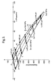
- a method for determining the residual stress and the thermally-induced stress in a rail comprising measuring the stresses in part of the rail remote from the railhead in a direction perpendicular to the longitudinal axis of the rail, and in a direction parallel to the longitudinal axis, determining from the stress in the perpendicular direction an estimate of the residual stress in the parallel direction, and hence by comparing the measured stress in the parallel direction to the estimated residual stress in the parallel direction determining the thermally-induced stress.
- the stress in the perpendicular direction is correlated with the residual stress in the parallel direction; in an alternative embodiment, the stress in the perpendicular direction is measured at different depths, and its variation with depth is correlated with the residual stress in the parallel direction.
- This alternative approach does not require absolute measurements of stress in the vertical direction, but only the difference in stress for different depths, and this may be desirable.
- the mapping requires a preliminary calibration, with a specimen of the material, to determine how the in-phase and quadrature components of the signal vary with lift-off (at a constant stress) and vary with stress (at a constant lift-off), and deducing from the calibration measurements the applicable mapping for any stress and any lift-off.
- the mapping may be represented in the impedance plane (i.e. on a graph of quadrature component against in-phase component) as two sets of contours representing signal variation with lift-off (for different values of stress) and signal variation with stress (for different values of lift-off), the contours of both sets being curved.
- the contours of one set intersect the contours of the other set at non-orthogonal angles.
- the electromagnet means comprises an electromagnetic core and two spaced apart electromagnetic poles
- the magnetic sensor is preferably arranged to sense the reluctance (or flux-linkage) of that part of the magnetic circuit between the poles of the electromagnet means. It is also desirable to arrange for such measurements to be taken with a plurality of different orientations of the magnetic field, at a single location on the object. This may be achieved using a single probe that is rotated at that location, measurements being taken with different orientations of the probe.
- the sensor provides a measure of the permeability of the material through which the flux passes between the poles; the corresponding measurements at different probe orientations at a location on the object hence indicate the effective permeability in different directions.
- the probe may also include a second magnetic sensor between the two poles and arranged to sense magnetic flux density perpendicular to the direction of the free space magnetic field between the poles.
- This second sensor would detect no signal if the material were exactly isotropic; however stress induces anisotropy into the magnetic properties of the material, and so the signals received by the second sensor (or flux-rotation sensor) are a measure of this stress-induced magnetic anisotropy.
- the variations in the flux rotation signals at different probe orientations, at a location on the object enable the directions of the principal stress axes to be accurately determined.
- the flux rotation signals can also be related to the stress.
- the probe may also include a third magnetic sensor (a flux-leakage sensor) between the poles arranged to sense magnetic flux density parallel to the free space magnetic field.
- This third sensor detects flux leakage which is influenced by changes in material properties, lift-off, and cracks.
- measurements at a location are preferably made at different probe orientations.
- the reluctance (or flux-linkage) signal from the probe is preferably backed-off, i.e. processed by first subtracting a signal equal to the signal from that sensor with the probe adjacent to a stress-free location. The backed-off signal is then amplified so the small changes due to stress are easier to detect.
- This backing off is performed after resolving into in-phase and quadrature components but before correcting for lift-off, for example by the mapping described above.
- the signals from the probe are digitized initially, and the backing-off and the lift-off correction are performed by analysis of the digital signals.
- the measurements at different probe orientations at a particular location would usually be obtained by rotating the probe, but alternatively might be obtained using an array of probes of different orientations that are successively moved to that location. It will be appreciated that measurements of stress at different depths below the surface, where this is required, may be achieved by generating the alternating magnetic field with different frequencies.
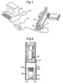
- a stress measuring apparatus 10 includes a sensor probe 12 comprising sensors for flux-linkage, flux-rotation and flux-leakage, the probe 12 being attached to an electric motor 14 which can be held by an operator, so the motor 14 can turn the probe 12 with one end adjacent to a surface of a steel object 16 (the web of a rail in this case) in which the stresses are to be determined.
- the sensor probe 12 and motor 14 are connected by a 2 m long umbilical cable 17 to a signal conditioning/probe driver unit 18.
- the unit 18 is connected by a long umbilical cable 19 (which may for example be up to 300 m long) to an interface unit within a microcomputer 20, which has a keyboard 21. Operation of the apparatus 10 is controlled by software in the microcomputer 20.
- the poles 28 are in the plane of the lower end of the casing 24, which is open.
- a former on which are wound two superimposed coils 30.
- One coil 30a (which has 200 turns) is supplied with the sinusoidal drive current from the unit 18; the other coil 30b (which has 70 turns) provides flux linkage signals.
- a former on which is wound a 1670-turn rectangular coil 32, about 4 mm high and 6 mm wide, and 6 mm-square as seen from below, the windings lying parallel to the plane of the figure so the longitudinal axis of the coil 32 is perpendicular to the line between the centres of the poles 28.
- the coil 32 is supported by a support plate 34 fixed between the arms of the U-core 26 so the lower face of the coil 32 is in the plane of the poles 28.
- the coil 32 provides the flux-rotation signals. If a flux-leakage signal is required, a coil may be wound on the same former but with windings perpendicular to the plane of the figure. All the signals are amplified by the head amplifier 25 before transmission to the unit 18.
- the motor 14 In operation of the system 10, the motor 14 is supported so the lower end of the probe 12 is adjacent to the surface of a steel object and the longitudinal axis of the probe 12 is normal to the surface.
- An alternating current of the desired frequency and amplitude is supplied to the drive coil 30a, so the magnetic field in the object 16 oscillates about zero with an amplitude much less than saturation.
- measurements are first made using an object of the same type of steel as the rail 16 but in which the stresses are negligible.
- the in-phase and quadrature components of the flux linkage signal i.e. the component in phase with the drive current, and the component differing in phase by 90°
- received by the microcomputer 20 are each backed off to zero, and the backing off values are then fixed.
- the flux linkage components are backed off by these same amounts (i.e. subtracting a signal equal to the component observed at a stress-free location).
- Stress measurements can be taken by placing the probe 12 adjacent to the web of the rail 16.
- the orientation of the line joining the centres of the poles 28 (referred to as the orientation of the probe 12) is noted relative to a fixed direction on the surface.
- the motor 14 is then energized to rotate the probe 12, for example in a step-wise fashion 10° at a time through a total angle of 360°. At each orientation of the probe 12 all the signals are measured.
Claims (8)
- Procédé destiné à déterminer la contrainte résiduelle et la contrainte causée par la condition thermique dans un rail, ledit procédé comprenant la mesure des contraintes dans une partie du rail éloignée du champignon du rail dans une direction perpendiculaire à l'axe longitudinal du rail, et dans une direction parallèle à l'axe longitudinal, déterminer à partir de la contrainte dans la direction perpendiculaire une estimation de la contrainte résiduelle dans la direction parallèle, et donc en comparant la contrainte mesurée dans la direction parallèle à la contrainte résiduelle estimée dans la direction parallèle déterminer la contrainte causée par la condition thermique.
- Procédé selon la revendication 1, dans lequel les contraintes sont mesurées dans les directions perpendiculaire et longitudinale dans l'âme du rail.
- Procédé selon la revendication 1 ou la revendication 2, dans lequel les contraintes sont mesurées en utilisant une sonde électromagnétique qui comprend un moyen d'électroaimant comprenant un noyau électromagnétique et deux pôles électromagnétiques espacés, et au moins un détecteur magnétique agencé pour détecter la réluctance de cette partie du circuit magnétique entre les pôles du moyen d'électroaimant, ou la fuite de flux entre les pôles du moyen d'électroaimant.
- Procédé selon l'une quelconque des revendications qui précèdent, dans lequel la contrainte résiduelle dans la direction longitudinale est déterminée à partir d'une corrélation entre celle-ci et la contrainte dans la direction perpendiculaire.
- Procédé selon l'une quelconque des revendications 1 à 3, dans lequel la contrainte résiduelle dans la direction longitudinale est déterminée à partir d'une corrélation entre celle-ci et la variation avec la profondeur de la contrainte dans la direction perpendiculaire.
- Procédé selon la revendication 4 dans lequel les contraintes sont mesurées en utilisant une sonde électromagnétique générant un champ magnétique alternatif, la fréquence du champ magnétique alternatif étant sélectionnée de telle sorte que la corrélation entre la contrainte longitudinale résiduelle et la contrainte perpendiculaire puisse être représentée par une droite sur le graphique de gradient 1.
- Procédé selon la revendication 5 dans lequel les contraintes sont mesurées en utilisant une sonde électromagnétique générant un champ magnétique alternatif, et la variation avec la profondeur de la contrainte dans la direction perpendiculaire est déterminée à partir des mesures à deux fréquences différentes du champ magnétique alternatif.
- Procédé selon la revendication 5 dans lequel les contraintes sont mesurées en utilisant une sonde électromagnétique générant un champ magnétique alternatif, et la variation avec la profondeur de la contrainte dans la direction perpendiculaire est déterminée en déconvolutionnant les mesures effectuées à plusieurs fréquences différentes du champ magnétique alternatif.
Applications Claiming Priority (3)
| Application Number | Priority Date | Filing Date | Title |
|---|---|---|---|
| GBGB0304192.8A GB0304192D0 (en) | 2003-02-25 | 2003-02-25 | Measurement of thermally induced stress |
| GB0304192 | 2003-02-25 | ||
| PCT/GB2004/000556 WO2004077003A1 (fr) | 2003-02-25 | 2004-02-13 | Mesure des contraintes residuelles et des contraintes d'origine thermique dans un rail |
Publications (2)
| Publication Number | Publication Date |
|---|---|
| EP1597553A1 EP1597553A1 (fr) | 2005-11-23 |
| EP1597553B1 true EP1597553B1 (fr) | 2006-12-13 |
Family
ID=9953553
Family Applications (1)
| Application Number | Title | Priority Date | Filing Date |
|---|---|---|---|
| EP04710918A Expired - Lifetime EP1597553B1 (fr) | 2003-02-25 | 2004-02-13 | Mesure des contraintes residuelles et des contraintes d'origine thermique dans un rail |
Country Status (10)
| Country | Link |
|---|---|
| US (1) | US7053606B2 (fr) |
| EP (1) | EP1597553B1 (fr) |
| JP (1) | JP4588694B2 (fr) |
| AT (1) | ATE348322T1 (fr) |
| AU (1) | AU2004215154B2 (fr) |
| DE (1) | DE602004003681T2 (fr) |
| ES (1) | ES2278303T3 (fr) |
| GB (1) | GB0304192D0 (fr) |
| NO (1) | NO20054392L (fr) |
| WO (1) | WO2004077003A1 (fr) |
Cited By (1)
| Publication number | Priority date | Publication date | Assignee | Title |
|---|---|---|---|---|
| CN105758463B (zh) * | 2016-04-15 | 2018-11-20 | 山西科为感控技术有限公司 | 无缝线路钢轨温度应力检测系统 |
Families Citing this family (29)
| Publication number | Priority date | Publication date | Assignee | Title |
|---|---|---|---|---|
| US9733625B2 (en) | 2006-03-20 | 2017-08-15 | General Electric Company | Trip optimization system and method for a train |
| US10308265B2 (en) | 2006-03-20 | 2019-06-04 | Ge Global Sourcing Llc | Vehicle control system and method |
| US9950722B2 (en) | 2003-01-06 | 2018-04-24 | General Electric Company | System and method for vehicle control |
| US9956974B2 (en) | 2004-07-23 | 2018-05-01 | General Electric Company | Vehicle consist configuration control |
| NL1028698C2 (nl) * | 2005-01-26 | 2006-07-31 | Grontmij Nederland B V | Systeem en werkwijze voor het ten minste detecteren van een mechanische spanning in ten minste een deel van een rail. |
| GB2429783A (en) * | 2005-09-06 | 2007-03-07 | Brian Gibbens | Stress free temperature variation monitor for railway tracks |
| US9828010B2 (en) | 2006-03-20 | 2017-11-28 | General Electric Company | System, method and computer software code for determining a mission plan for a powered system using signal aspect information |
| US8852504B2 (en) * | 2006-10-11 | 2014-10-07 | The Board Of Trustees Of The University Of Illinois | Apparatus and method for detecting and identifying microorganisms |
| US20080201089A1 (en) * | 2007-01-11 | 2008-08-21 | Ensco, Inc. | System and method for determining neutral temperature of a metal |
| GB0718525D0 (en) * | 2007-09-24 | 2007-10-31 | Maps Technology Ltd | Material conditioning technique |
| US8914171B2 (en) | 2012-11-21 | 2014-12-16 | General Electric Company | Route examining system and method |
| NL2006395C2 (en) * | 2011-03-15 | 2012-09-18 | Grontmij Nederland B V | System for calibrating and measuring mechanical stress in at least a part of a rail. |
| RU2454344C1 (ru) * | 2011-04-28 | 2012-06-27 | Общество с ограниченной ответственностью "Научно-Технический Центр Информационные Технологии" | Способ контроля рельсовых плетей бесстыкового железнодорожного пути |
| AU2013299501B2 (en) | 2012-08-10 | 2017-03-09 | Ge Global Sourcing Llc | Route examining system and method |
| CN102889955A (zh) * | 2012-10-10 | 2013-01-23 | 北京理工大学 | 一种钢轨残余应力的超声检测简易夹持装置 |
| EP2789998B1 (fr) * | 2013-04-08 | 2015-06-10 | Bayern Engineering GmbH & Co. KG | Système de rail de transport avec un moyen de pesée |
| US9255913B2 (en) | 2013-07-31 | 2016-02-09 | General Electric Company | System and method for acoustically identifying damaged sections of a route |
| JP5955301B2 (ja) * | 2013-11-14 | 2016-07-20 | 株式会社神戸製鋼所 | 残留応力算出方法 |
| CN106289606B (zh) * | 2015-05-20 | 2019-08-27 | 北京中科用通科技股份有限公司 | 扣件纵向阻力测试装置 |
| CN107314844A (zh) * | 2017-06-05 | 2017-11-03 | 内蒙古包钢钢联股份有限公司 | 钢轨残余应力实验卡具及其实验方法 |
| CN108195930B (zh) * | 2018-01-08 | 2021-12-21 | 沈阳工业大学 | 一种磁记忆移动扫描式声光报警系统 |
| CN108152364A (zh) * | 2018-01-08 | 2018-06-12 | 沈阳工业大学 | 一种新型磁记忆定点声光报警控制方法 |
| CN108181376B (zh) * | 2018-01-08 | 2021-12-21 | 沈阳工业大学 | 一种磁记忆定点声光报警系统 |
| CN108195929A (zh) * | 2018-01-08 | 2018-06-22 | 沈阳工业大学 | 一种新型磁记忆移动扫描式声光报警控制方法 |
| CN109682502B (zh) * | 2018-12-31 | 2023-11-03 | 浙江大学 | 一种定量评估导电游丝残余应力变化的装置 |
| CN110441720A (zh) * | 2019-09-12 | 2019-11-12 | 河北工业大学 | 一种在叠制方向施加应力的改进爱泼斯坦方圈 |
| CN111024285A (zh) * | 2019-11-18 | 2020-04-17 | 包头钢铁(集团)有限责任公司 | 一种采用线切割测试钢轨残余应力的试验方法 |
| CN111207868B (zh) * | 2020-01-19 | 2021-03-12 | 山东大学 | 一种基于磁弹效应的平面残余应力自动检测装置及方法 |
| CN114739556B (zh) * | 2022-06-13 | 2022-09-06 | 中铝材料应用研究院有限公司 | 二次剖切轮廓法残余应力测试方法 |
Family Cites Families (12)
| Publication number | Priority date | Publication date | Assignee | Title |
|---|---|---|---|---|
| GB2022268B (en) * | 1978-06-02 | 1983-01-19 | Shibaura Eng Works Ltd | Stress measuring apparatus |
| JPS58213903A (ja) * | 1982-06-04 | 1983-12-13 | 財団法人 鉄道総合技術研究所 | レ−ル軸力検出装置 |
| JPS58216924A (ja) * | 1982-06-11 | 1983-12-16 | Japanese National Railways<Jnr> | 軌道応力検測方式 |
| WO1989001613A1 (fr) | 1987-08-10 | 1989-02-23 | Hutchinson Ian Nigel | Determination non destructive de caracteristiques de contrainte dans des materiaux magnetiques |
| GB9310803D0 (en) * | 1993-05-21 | 1993-07-14 | Atomic Energy Authority Uk | Stress measurement |
| JP2849038B2 (ja) | 1994-04-08 | 1999-01-20 | 新日本製鐵株式会社 | レール軸力測定方法および軸力測定可能なレール |
| HU219436B (hu) * | 1995-05-09 | 2001-04-28 | Magyar Államvasutak Rt. | Eljárás és berendezés hézag nélküli vágányok semleges hőmérsékletének meghatározására |
| US6657429B1 (en) * | 1995-08-25 | 2003-12-02 | Jentek Sensors, Inc. | Material condition assessment with spatially periodic field sensors |
| JP3644628B2 (ja) * | 2000-03-31 | 2005-05-11 | 財団法人鉄道総合技術研究所 | 磁気異方性センサを用いた応力測定方法及び装置 |
| GB0124910D0 (en) * | 2001-10-17 | 2001-12-05 | Accentus Plc | Measurement of material properties |
| WO2003034054A2 (fr) | 2001-10-17 | 2003-04-24 | Aea Technology Plc | Mesure avec un champ magnetique |
| US7526964B2 (en) * | 2002-01-25 | 2009-05-05 | Jentek Sensors, Inc. | Applied and residual stress measurements using magnetic field sensors |
-
2003
- 2003-02-25 GB GBGB0304192.8A patent/GB0304192D0/en not_active Ceased
-
2004
- 2004-02-13 JP JP2006502269A patent/JP4588694B2/ja not_active Expired - Fee Related
- 2004-02-13 US US10/535,211 patent/US7053606B2/en not_active Expired - Fee Related
- 2004-02-13 DE DE602004003681T patent/DE602004003681T2/de not_active Expired - Lifetime
- 2004-02-13 AT AT04710918T patent/ATE348322T1/de active
- 2004-02-13 EP EP04710918A patent/EP1597553B1/fr not_active Expired - Lifetime
- 2004-02-13 WO PCT/GB2004/000556 patent/WO2004077003A1/fr active IP Right Grant
- 2004-02-13 ES ES04710918T patent/ES2278303T3/es not_active Expired - Lifetime
- 2004-02-13 AU AU2004215154A patent/AU2004215154B2/en not_active Ceased
-
2005
- 2005-09-22 NO NO20054392A patent/NO20054392L/no not_active Application Discontinuation
Cited By (1)
| Publication number | Priority date | Publication date | Assignee | Title |
|---|---|---|---|---|
| CN105758463B (zh) * | 2016-04-15 | 2018-11-20 | 山西科为感控技术有限公司 | 无缝线路钢轨温度应力检测系统 |
Also Published As
| Publication number | Publication date |
|---|---|
| AU2004215154B2 (en) | 2008-10-30 |
| US7053606B2 (en) | 2006-05-30 |
| US20060028205A1 (en) | 2006-02-09 |
| WO2004077003A1 (fr) | 2004-09-10 |
| EP1597553A1 (fr) | 2005-11-23 |
| DE602004003681T2 (de) | 2007-10-25 |
| ES2278303T3 (es) | 2007-08-01 |
| ATE348322T1 (de) | 2007-01-15 |
| AU2004215154A1 (en) | 2004-09-10 |
| NO20054392L (no) | 2005-09-22 |
| DE602004003681D1 (de) | 2007-01-25 |
| JP2006518848A (ja) | 2006-08-17 |
| GB0304192D0 (en) | 2003-03-26 |
| JP4588694B2 (ja) | 2010-12-01 |
Similar Documents
| Publication | Publication Date | Title |
|---|---|---|
| EP1597553B1 (fr) | Mesure des contraintes residuelles et des contraintes d'origine thermique dans un rail | |
| US6850055B2 (en) | Measurement of the variation of a material property with depth in a ferromagnetic material | |
| US4528856A (en) | Eddy current stress-strain gauge | |
| US7215117B2 (en) | Measurement with a magnetic field | |
| US5828211A (en) | Determining stress in ferromagnetic materials from measurements of magnetic anisotropy and magnetic permeability | |
| JP2007040865A (ja) | 硬化層深さ・未焼入れ・異材判定の非破壊測定法 | |
| US8316726B2 (en) | Biaxial stress management | |
| Buttle | Magnetic methods | |
| JP2005127963A (ja) | 非破壊検査方法及びその装置 | |
| JPH06271926A (ja) | 焼入硬化層深さの非破壊測定方法 | |
| Alonso et al. | Magnetostatic determination of variations of internal stress in magnetic steels | |
| Mukherjee et al. | Phase sensitive detection of extent of corrosion in steel reinforcing bars using eddy currents | |
| JP4128297B2 (ja) | 鋼管の応力診断方法 | |
| Stegemann et al. | Evaluation of high spatial resolution imaging of magnetic stray fields for early damage detection | |
| Kim et al. | Non-destructive surface profiling and inspection by using a single unit magneto-eddy current sensor | |
| JP3159132B2 (ja) | 鋼管の応力の測定方法 | |
| Buttle et al. | Determination of residual stresses by magnetic methods. | |
| US20180164250A1 (en) | Eddy current probe and a method of using the same | |
| Lotsberg et al. | Stress measurements at hot spots using StressProbe | |
| JPS63205558A (ja) | 亀裂深さの計測方法 | |
| Delgado et al. | Determination of Residual Stresses on a Centrifugal Compressor Impeller | |
| Govindaraju et al. | Finite-element analysis of a magnetic sensor to detect permeability changes due to residual stresses in ferromagnetic materials | |
| Dziczkowski et al. | Modyfikacja metody skalowania konduktometru | |
| Langman | Magnetic stress analysis of structural steel | |
| Sato et al. | Electromagnetic Nondestructive Evaluation (V) 159 J. Pávó et al.(Eds.) IOS Press, 2001 |
Legal Events
| Date | Code | Title | Description |
|---|---|---|---|
| PUAI | Public reference made under article 153(3) epc to a published international application that has entered the european phase |
Free format text: ORIGINAL CODE: 0009012 |
|
| 17P | Request for examination filed |
Effective date: 20050506 |
|
| AK | Designated contracting states |
Kind code of ref document: A1 Designated state(s): AT BE BG CH CY CZ DE DK EE ES FI FR GB GR HU IE IT LI LU MC NL PT RO SE SI SK TR |
|
| AX | Request for extension of the european patent |
Extension state: AL LT LV MK |
|
| RAP1 | Party data changed (applicant data changed or rights of an application transferred) |
Owner name: ESR TECHNOLOGY LTD |
|
| DAX | Request for extension of the european patent (deleted) | ||
| GRAP | Despatch of communication of intention to grant a patent |
Free format text: ORIGINAL CODE: EPIDOSNIGR1 |
|
| GRAS | Grant fee paid |
Free format text: ORIGINAL CODE: EPIDOSNIGR3 |
|
| GRAA | (expected) grant |
Free format text: ORIGINAL CODE: 0009210 |
|
| AK | Designated contracting states |
Kind code of ref document: B1 Designated state(s): AT BE BG CH CY CZ DE DK EE ES FI FR GB GR HU IE IT LI LU MC NL PT RO SE SI SK TR |
|
| PG25 | Lapsed in a contracting state [announced via postgrant information from national office to epo] |
Ref country code: SI Free format text: LAPSE BECAUSE OF FAILURE TO SUBMIT A TRANSLATION OF THE DESCRIPTION OR TO PAY THE FEE WITHIN THE PRESCRIBED TIME-LIMIT Effective date: 20061213 Ref country code: DK Free format text: LAPSE BECAUSE OF FAILURE TO SUBMIT A TRANSLATION OF THE DESCRIPTION OR TO PAY THE FEE WITHIN THE PRESCRIBED TIME-LIMIT Effective date: 20061213 Ref country code: FI Free format text: LAPSE BECAUSE OF FAILURE TO SUBMIT A TRANSLATION OF THE DESCRIPTION OR TO PAY THE FEE WITHIN THE PRESCRIBED TIME-LIMIT Effective date: 20061213 Ref country code: SK Free format text: LAPSE BECAUSE OF FAILURE TO SUBMIT A TRANSLATION OF THE DESCRIPTION OR TO PAY THE FEE WITHIN THE PRESCRIBED TIME-LIMIT Effective date: 20061213 Ref country code: CZ Free format text: LAPSE BECAUSE OF FAILURE TO SUBMIT A TRANSLATION OF THE DESCRIPTION OR TO PAY THE FEE WITHIN THE PRESCRIBED TIME-LIMIT Effective date: 20061213 Ref country code: RO Free format text: LAPSE BECAUSE OF FAILURE TO SUBMIT A TRANSLATION OF THE DESCRIPTION OR TO PAY THE FEE WITHIN THE PRESCRIBED TIME-LIMIT Effective date: 20061213 |
|
| REG | Reference to a national code |
Ref country code: GB Ref legal event code: FG4D |
|
| REG | Reference to a national code |
Ref country code: CH Ref legal event code: EP |
|
| REG | Reference to a national code |
Ref country code: IE Ref legal event code: FG4D |
|
| REF | Corresponds to: |
Ref document number: 602004003681 Country of ref document: DE Date of ref document: 20070125 Kind code of ref document: P |
|
| REG | Reference to a national code |
Ref country code: CH Ref legal event code: NV Representative=s name: E. BLUM & CO. AG PATENT- UND MARKENANWAELTE VSP |
|
| PG25 | Lapsed in a contracting state [announced via postgrant information from national office to epo] |
Ref country code: MC Free format text: LAPSE BECAUSE OF NON-PAYMENT OF DUE FEES Effective date: 20070228 |
|
| PG25 | Lapsed in a contracting state [announced via postgrant information from national office to epo] |
Ref country code: BG Free format text: LAPSE BECAUSE OF FAILURE TO SUBMIT A TRANSLATION OF THE DESCRIPTION OR TO PAY THE FEE WITHIN THE PRESCRIBED TIME-LIMIT Effective date: 20070313 |
|
| REG | Reference to a national code |
Ref country code: SE Ref legal event code: TRGR |
|
| ET | Fr: translation filed | ||
| PG25 | Lapsed in a contracting state [announced via postgrant information from national office to epo] |
Ref country code: PT Free format text: LAPSE BECAUSE OF FAILURE TO SUBMIT A TRANSLATION OF THE DESCRIPTION OR TO PAY THE FEE WITHIN THE PRESCRIBED TIME-LIMIT Effective date: 20070514 |
|
| REG | Reference to a national code |
Ref country code: ES Ref legal event code: FG2A Ref document number: 2278303 Country of ref document: ES Kind code of ref document: T3 |
|
| PLBE | No opposition filed within time limit |
Free format text: ORIGINAL CODE: 0009261 |
|
| STAA | Information on the status of an ep patent application or granted ep patent |
Free format text: STATUS: NO OPPOSITION FILED WITHIN TIME LIMIT |
|
| 26N | No opposition filed |
Effective date: 20070914 |
|
| REG | Reference to a national code |
Ref country code: CH Ref legal event code: PUE Owner name: MAPS TECHNOLOGY LIMITED Free format text: ESR TECHNOLOGY LTD#WHITTLE HOUSE 410 THE QUADRANT#BIRCHWOOD PARK WARRINGTON CHESHIRE WA3 6FW (GB) -TRANSFER TO- MAPS TECHNOLOGY LIMITED#16 NORTH CENTRAL 127 MILTON PARK#ABINGDON, OXFORDSHIRE OX14 4SA (GB) |
|
| REG | Reference to a national code |
Ref country code: GB Ref legal event code: 732E |
|
| BECA | Be: change of holder's address |
Owner name: MAPS TECHNOLOGY LTD16 NORTH CENTRAL, 127 MILTON PA Effective date: 20061213 |
|
| BECH | Be: change of holder |
Owner name: MAPS TECHNOLOGY LTD Effective date: 20061213 |
|
| NLS | Nl: assignments of ep-patents |
Owner name: MAPS TECHNOLOGY LIMITED Effective date: 20071105 |
|
| PG25 | Lapsed in a contracting state [announced via postgrant information from national office to epo] |
Ref country code: IE Free format text: LAPSE BECAUSE OF NON-PAYMENT OF DUE FEES Effective date: 20070213 |
|
| REG | Reference to a national code |
Ref country code: ES Ref legal event code: PC2A |
|
| REG | Reference to a national code |
Ref country code: FR Ref legal event code: TP |
|
| PG25 | Lapsed in a contracting state [announced via postgrant information from national office to epo] |
Ref country code: GR Free format text: LAPSE BECAUSE OF FAILURE TO SUBMIT A TRANSLATION OF THE DESCRIPTION OR TO PAY THE FEE WITHIN THE PRESCRIBED TIME-LIMIT Effective date: 20070314 |
|
| PG25 | Lapsed in a contracting state [announced via postgrant information from national office to epo] |
Ref country code: EE Free format text: LAPSE BECAUSE OF FAILURE TO SUBMIT A TRANSLATION OF THE DESCRIPTION OR TO PAY THE FEE WITHIN THE PRESCRIBED TIME-LIMIT Effective date: 20061213 |
|
| PG25 | Lapsed in a contracting state [announced via postgrant information from national office to epo] |
Ref country code: LU Free format text: LAPSE BECAUSE OF NON-PAYMENT OF DUE FEES Effective date: 20070213 Ref country code: CY Free format text: LAPSE BECAUSE OF FAILURE TO SUBMIT A TRANSLATION OF THE DESCRIPTION OR TO PAY THE FEE WITHIN THE PRESCRIBED TIME-LIMIT Effective date: 20061213 |
|
| PG25 | Lapsed in a contracting state [announced via postgrant information from national office to epo] |
Ref country code: HU Free format text: LAPSE BECAUSE OF FAILURE TO SUBMIT A TRANSLATION OF THE DESCRIPTION OR TO PAY THE FEE WITHIN THE PRESCRIBED TIME-LIMIT Effective date: 20070614 Ref country code: TR Free format text: LAPSE BECAUSE OF FAILURE TO SUBMIT A TRANSLATION OF THE DESCRIPTION OR TO PAY THE FEE WITHIN THE PRESCRIBED TIME-LIMIT Effective date: 20061213 |
|
| REG | Reference to a national code |
Ref country code: FR Ref legal event code: PLFP Year of fee payment: 12 |
|
| PGFP | Annual fee paid to national office [announced via postgrant information from national office to epo] |
Ref country code: DE Payment date: 20150226 Year of fee payment: 12 Ref country code: ES Payment date: 20150226 Year of fee payment: 12 Ref country code: CH Payment date: 20150226 Year of fee payment: 12 Ref country code: NL Payment date: 20150225 Year of fee payment: 12 Ref country code: IT Payment date: 20150225 Year of fee payment: 12 |
|
| PGFP | Annual fee paid to national office [announced via postgrant information from national office to epo] |
Ref country code: SE Payment date: 20150226 Year of fee payment: 12 Ref country code: FR Payment date: 20150217 Year of fee payment: 12 Ref country code: AT Payment date: 20150121 Year of fee payment: 12 Ref country code: GB Payment date: 20150226 Year of fee payment: 12 |
|
| PGFP | Annual fee paid to national office [announced via postgrant information from national office to epo] |
Ref country code: BE Payment date: 20150226 Year of fee payment: 12 |
|
| PG25 | Lapsed in a contracting state [announced via postgrant information from national office to epo] |
Ref country code: BE Free format text: LAPSE BECAUSE OF NON-PAYMENT OF DUE FEES Effective date: 20160229 |
|
| REG | Reference to a national code |
Ref country code: DE Ref legal event code: R119 Ref document number: 602004003681 Country of ref document: DE |
|
| REG | Reference to a national code |
Ref country code: CH Ref legal event code: PL |
|
| REG | Reference to a national code |
Ref country code: SE Ref legal event code: EUG |
|
| REG | Reference to a national code |
Ref country code: AT Ref legal event code: MM01 Ref document number: 348322 Country of ref document: AT Kind code of ref document: T Effective date: 20160213 |
|
| GBPC | Gb: european patent ceased through non-payment of renewal fee |
Effective date: 20160213 |
|
| PG25 | Lapsed in a contracting state [announced via postgrant information from national office to epo] |
Ref country code: LI Free format text: LAPSE BECAUSE OF NON-PAYMENT OF DUE FEES Effective date: 20160229 Ref country code: CH Free format text: LAPSE BECAUSE OF NON-PAYMENT OF DUE FEES Effective date: 20160229 |
|
| REG | Reference to a national code |
Ref country code: NL Ref legal event code: MM Effective date: 20160301 |
|
| REG | Reference to a national code |
Ref country code: FR Ref legal event code: ST Effective date: 20161028 |
|
| PG25 | Lapsed in a contracting state [announced via postgrant information from national office to epo] |
Ref country code: SE Free format text: LAPSE BECAUSE OF NON-PAYMENT OF DUE FEES Effective date: 20160214 Ref country code: AT Free format text: LAPSE BECAUSE OF NON-PAYMENT OF DUE FEES Effective date: 20160213 |
|
| PG25 | Lapsed in a contracting state [announced via postgrant information from national office to epo] |
Ref country code: IT Free format text: LAPSE BECAUSE OF NON-PAYMENT OF DUE FEES Effective date: 20160213 |
|
| PG25 | Lapsed in a contracting state [announced via postgrant information from national office to epo] |
Ref country code: DE Free format text: LAPSE BECAUSE OF NON-PAYMENT OF DUE FEES Effective date: 20160901 Ref country code: GB Free format text: LAPSE BECAUSE OF NON-PAYMENT OF DUE FEES Effective date: 20160213 Ref country code: NL Free format text: LAPSE BECAUSE OF NON-PAYMENT OF DUE FEES Effective date: 20160301 Ref country code: FR Free format text: LAPSE BECAUSE OF NON-PAYMENT OF DUE FEES Effective date: 20160229 |
|
| PG25 | Lapsed in a contracting state [announced via postgrant information from national office to epo] |
Ref country code: ES Free format text: LAPSE BECAUSE OF NON-PAYMENT OF DUE FEES Effective date: 20160214 |