EP1597504B1 - Fire collar - Google Patents
Fire collar Download PDFInfo
- Publication number
- EP1597504B1 EP1597504B1 EP20040709552 EP04709552A EP1597504B1 EP 1597504 B1 EP1597504 B1 EP 1597504B1 EP 20040709552 EP20040709552 EP 20040709552 EP 04709552 A EP04709552 A EP 04709552A EP 1597504 B1 EP1597504 B1 EP 1597504B1
- Authority
- EP
- European Patent Office
- Prior art keywords
- fire
- conduit
- fire collar
- collar according
- collar
- Prior art date
- Legal status (The legal status is an assumption and is not a legal conclusion. Google has not performed a legal analysis and makes no representation as to the accuracy of the status listed.)
- Expired - Lifetime
Links
Images


Classifications
-
- F—MECHANICAL ENGINEERING; LIGHTING; HEATING; WEAPONS; BLASTING
- F16—ENGINEERING ELEMENTS AND UNITS; GENERAL MEASURES FOR PRODUCING AND MAINTAINING EFFECTIVE FUNCTIONING OF MACHINES OR INSTALLATIONS; THERMAL INSULATION IN GENERAL
- F16L—PIPES; JOINTS OR FITTINGS FOR PIPES; SUPPORTS FOR PIPES, CABLES OR PROTECTIVE TUBING; MEANS FOR THERMAL INSULATION IN GENERAL
- F16L55/00—Devices or appurtenances for use in, or in connection with, pipes or pipe systems
- F16L55/10—Means for stopping flow in pipes or hoses
- F16L55/1026—Fire protection devices
-
- F—MECHANICAL ENGINEERING; LIGHTING; HEATING; WEAPONS; BLASTING
- F16—ENGINEERING ELEMENTS AND UNITS; GENERAL MEASURES FOR PRODUCING AND MAINTAINING EFFECTIVE FUNCTIONING OF MACHINES OR INSTALLATIONS; THERMAL INSULATION IN GENERAL
- F16L—PIPES; JOINTS OR FITTINGS FOR PIPES; SUPPORTS FOR PIPES, CABLES OR PROTECTIVE TUBING; MEANS FOR THERMAL INSULATION IN GENERAL
- F16L5/00—Devices for use where pipes, cables or protective tubing pass through walls or partitions
- F16L5/02—Sealing
- F16L5/04—Sealing to form a firebreak device
-
- F—MECHANICAL ENGINEERING; LIGHTING; HEATING; WEAPONS; BLASTING
- F16—ENGINEERING ELEMENTS AND UNITS; GENERAL MEASURES FOR PRODUCING AND MAINTAINING EFFECTIVE FUNCTIONING OF MACHINES OR INSTALLATIONS; THERMAL INSULATION IN GENERAL
- F16L—PIPES; JOINTS OR FITTINGS FOR PIPES; SUPPORTS FOR PIPES, CABLES OR PROTECTIVE TUBING; MEANS FOR THERMAL INSULATION IN GENERAL
- F16L57/00—Protection of pipes or objects of similar shape against external or internal damage or wear
- F16L57/04—Protection of pipes or objects of similar shape against external or internal damage or wear against fire or other external sources of extreme heat
-
- A—HUMAN NECESSITIES
- A62—LIFE-SAVING; FIRE-FIGHTING
- A62C—FIRE-FIGHTING
- A62C2/00—Fire prevention or containment
- A62C2/06—Physical fire-barriers
- A62C2/065—Physical fire-barriers having as the main closure device materials, whose characteristics undergo an irreversible change under high temperatures, e.g. intumescent
-
- Y—GENERAL TAGGING OF NEW TECHNOLOGICAL DEVELOPMENTS; GENERAL TAGGING OF CROSS-SECTIONAL TECHNOLOGIES SPANNING OVER SEVERAL SECTIONS OF THE IPC; TECHNICAL SUBJECTS COVERED BY FORMER USPC CROSS-REFERENCE ART COLLECTIONS [XRACs] AND DIGESTS
- Y10—TECHNICAL SUBJECTS COVERED BY FORMER USPC
- Y10T—TECHNICAL SUBJECTS COVERED BY FORMER US CLASSIFICATION
- Y10T137/00—Fluid handling
- Y10T137/1624—Destructible or deformable element controlled
- Y10T137/1797—Heat destructible or fusible
- Y10T137/1819—Safety cut-off
Definitions
- This invention relates to a device for preventing fire from spreading from one side of a barrier, such as a wall, floor, partition or the like, in a structure, to the other side through pipework or ducting which extends through the barrier.
- a barrier such as a wall, floor, partition or the like
- the invention is primarily concerned with a new form of fire collar for location in concrete slabs forming the floors and walls of multi-storey buildings.
- Fire dampers are generally located in a barrier and are connected to pipework or ducting. They include a passage which may be closed by a valve arrangement when a fire on one side of the barrier triggers a heat detector incorporated in the damper.
- An example of this type of fire damper is described in WO 03/023267 Al .
- Fire collars are usually employed with pipework or ducting which are formed from a deformable material including a plastics material such as PVC, rubber, or a deformable metal or composite material.
- a common type of fire collar comprises a metal collar which is fastened around a concrete slab-penetrating pipe formed from a plastics material, in the region where it traverses the slab. The collar encloses an intumescent material. When a fire on one side of the concrete slab reaches a sufficient intensity, it causes the intumescent material to expand, which in turn collapses or pinches off the deformable pipe. In this way, fire is prevented from spreading to the other side of the concrete slab by passing through the conduit.
- fire collars examples include US-A-5, 058 346 and US-A- 5,347,767 .
- the heat of the fire melts the pipe where it penetrates the slab, and the subsequent expansion of the intumescent material seals off the void left by the melted pipe.
- a major problem with prior art fire collars is that in rapidly advancing fires the time taken for the intumescent material to seal off the pipe or the void left by a melted pipe can be too long, as a result of which the fire is still able to spread to the other side of the barrier.
- the invention provides a fire collar for preventing the spread of fire from one side of a barrier to the other side of said barrier, said fire collar being adapted to be located in said barrier and to surround or incorporate a deformable conduit which traverses said barrier, said fire collar being further adapted to respond to said fire by collapsing said deformable conduit, wherein said fire collar includes clamp means, said clamp means is retained in a first position by retaining means, and said retaining means is actuated when a predetermined temperature is reached as a result of said fire, such that said clamp means is released, thereby moving towards a second position whereby it firstly contacts said conduit and then collapses said conduit; characterised in that said clamp means includes an actuating member that is an arm which is normally biased towards said second position; and said arm constitutes one end of a torsion spring, the force of said torsion spring biasing said arm towards said second position.
- carrier is to be taken to mean a wall, a floor (particularly a slab floor of the type used in multi-storey buildings), a partition or the like, which are features of structures such as buildings.
- conduit is intended to refer to a pipe, pipework, a conduit, a duct, or the like, features of structures such as buildings.
- Pipework and ducting are used to carry fluids within many structures. Fluids carried by pipework and ducting include gases, such as airconditioning air and waste gases, and liquids such as liquid wastes and water. Conduits are used to carry cabling such as electrical cables, telephones cables, computer network cables, fibre optic cables and the like. In many structures it is necessary to minimise the likelihood of fire being propagated between regions within the structure. For example, in multi-storey buildings, pipes, conduits and ducting pass through partitions such as the concrete slabs between storeys. The fire collar of the present invention is suitable for a wide variety of pipework, conduits and ducting which is used for various purposes.
- the fire collar of an embodiment of the invention is intended, in use, to collapse a deformable conduit in the event that a fire occurs on one side of the barrier in which the fire collar is situated.
- a fire collar may be mounted over pipework or ducting where the pipework or ducting is itself deformable and the pipework or ducting thus forms the deformable conduit.
- the collar may be provided with a deformable collar extending therethrough, the deformable conduit having adapters at either end to receive, or to be received in, the pipework or ducting.
- the deformable conduit may be of any convenient cross-section, adapted to integrate with the pipework or ducting.
- the deformable conduit may be formed from any convenient deformable material.
- Suitable deformable materials include plastics materials such as PVC and rubber, or a deformable metal or composite material.
- the term "deformable" in this context means that the conduit is elastically or plastically deformable to the extent necessary for the conduit to be substantially collapsed or pinched off.
- the deformable conduit may be a PVC pipe that, at the temperatures to which the pipe may be subjected in a fire, is capable of such deformation.
- these material properties of the conduit are applicable at the temperature and conditions under which the conduit is required to collapse. For instance, whilst a PVC pipe may be incapable of deforming to the point of collapse at room temperature, at the particular temperature to which the pipe is subjected in the case of fire, the conduit will be able to be collapsed under pressure from the clamp means.
- the fire collar of an embodiment of the present invention may be of any convenient shape and preferably has a passage therethrough for receiving a deformable conduit.
- the passage through the collar will have a sufficiently large cross-section to accommodate the deformation of the conduit when it collapses.
- the clamp may be disposed within the collar.
- the clamp may be mounted on an external surface of the collar.
- the clamp and associated detents are disposed within the collar for free movement in the absence of interference from the concrete slab.
- the collar may be formed of any convenient material, including plastics material.
- the collar may be moulded.
- the collar will include intumescent material such that in the case of fire the intumescent material of the collar will expand and further collapse the deformable conduit to provide improved sealing of the conduit and minimise the propagation of any fire through the barrier.
- the clamp means may be formed from one or more moveable arms and may include a fixed anvil against which the one or more moveable arms may bear in a normal orientation.
- the clamp comprises a pair of opposed arms between which the deformable conduit is collapsed in response to a fire on one side of the barrier.
- the clamp is normally biased to a second position, in which the clamp arms bear upon the deformable conduit and collapse it.
- the clamp is biased to the second position using a torsion spring.
- the moveable arm or arms of the clamp are biased by a torsion spring.
- the clamp is provided by a pair of opposed arms pivotally mounted within the collar on opposite sides of the deformable conduit.
- the opposed arms may be formed from spring steel and be part of a coil torsion spring pivoted at a spring mount.
- One end of the coil torsion spring forms the moveable arm of the clamp.
- the other end of the coil torsion spring extends from the coil and is retained against rotation in the collar such that on rotation of the moveable arm to a first position, energy is stored in the spring arm.
- a detent retains the torsion spring arm in the first position.
- Each of the pair of opposed arms is biased such that each will, upon release, move across the passage through the collar. With a deformable conduit in place the respective arms will collapse the deformable conduit diametrically across the passage through the collar.
- the fire collar has opposed moveable arms such that the deformable conduit is collapsed substantially diametrically. It has been found that collapsing the deformable conduit utilising two opposed arms is quicker than using a single moveable arm against an anvil, as a single arm is required to travel across the entirety of the passage in order to completely collapse the deformable conduit, whereas each of two opposed arms only has to travel about half-way across the passage.
- the clamp may be retained in the first position by at least one detent.
- the detent may be fusible or frangible.
- the detent may be formed from a material that has the dual properties of, firstly, being able to retain the clamp in the first position under normal conditions and, secondly, being able to yield when heated to a predetermined temperature of the type encountered when there is a fire on one side of the barrier in which the fire collar is located. These properties enable the detent to be designed as a heat detector and located in a manner that will retain the clamp in the first position but, when a predetermined temperature is reached, to yield, enabling the clamp to move to the second position and thereby to collapse the conduit.
- Suitable heat detector materials from which the detent may be formed include lead and its alloys, plastics materials and various composites. Typically, the temperature at which such materials yield will be in the range of 60°C to 120°C, depending upon the particular application, so as to meet governmental or local council requirements.
- the detent can be operated by a thermocouple or other temperature or smoke sensor.
- the sensor can be connected by way of appropriate circuitry to a solenoid which can retract or release the detent to permit the clamp to close when the sensor detects a predetermined temperature value.
- the deformable conduit may be encased in a sleeve of intumescent material.
- Encasing the deformable conduit in a sleeve of intumescent material advantageously accelerates the closing of the deformable conduit at elevated temperatures such as those encountered during a fire.
- the sleeve of intumescent material is preferably enclosed by an outer sleeve of a flexible yet inelastic material such as a glass cloth. Encasing the intumescent sleeve with an outer layer of glass cloth prevents the intumescent material expanding outwards, directing the expansion inwards, which forces the further collapse of the deformable conduit.
- Fig. 1 is an underneath view of one embodiment of a fire collar according to the embodiment of the present invention
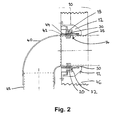
- Fig. 2 is a cross-sectional view of the collar of Fig. 1 , located in a concrete slab
- Fig 3 is an underneath view of a fire collar according to another embodiment of the present invention
- Fig. 4 is a cross-sectional view of the collar of Fig. 3 , located in a concrete slab.
- Fig. 1 shows a fire collar 10 which is adapted to surround a pipe, conduit, duct or the like 14.
- the fire collar 10 includes a housing 12 which has a passage 16 extending therethrough, in which passage 16 a PVC conduit 14 is disposed.
- the springs 18, 20 are substantially identical, and are located within housing 12 on opposite sides of the passage 16.
- Each spring 18, 20 is a torsion spring.
- Spring 18 is pivotally located on a spring mount 22, and spring 20 is pivotally located on a spring mount 24.
- One end 26 of spring 18 is permanently restrained by housing 12 against rotational movement about mount 22, and one end 28 of spring 20 is permanently restrained by housing 12 against rotational movement about mount 24.
- the other end 30 of spring 18 is extended, forming an arm, and the other end 32 of spring 20 is also extended, forming an arm.
- Arm 30 is held in place against the force of spring 18, under a normal situation, by a detent 34, which may be a fusible link spring arm release, and arm 32 is held in place against the force of spring 20, under a normal situation, by a detent 36, which may be a fusible link spring arm release.
- the detents 34, 36 may take any form, so long as they operate at a predetermined temperature, releasing the arms 30, 32 to move under the respective forces of springs 18, 20 towards the second position in the direction of the arrows depicted in Fig. 1 .
- fusible link 34, 36 which may be preferred is a conventional cable tie, used normally to secure bundles of such things as reinforcing rods and the like.
- Cable ties are formed from a plastics material which will at least soften and possibly melt at the kind of temperatures found when a fire is present on one side of the slab 46, which would then allow arms 30, 32 to move under the force of springs 18,20 to collapse. Under normal circumstances, cable ties would operate ideally to retain the arms 30, 32 in the first position, and would be applied in much the same way as occurs with the conventional use of such ties.
- the passage 16 substantially follows the outer profile of the conduit 14, but is extended laterally so that it can accommodate deformation of the conduit 14 in the manner to be described hereinafter.
- the lateral extension of the passageway 16 minimises the resistance of the conduit to collapse.
- the conduit 14 is formed by interlocking conduits 38, 40 respectively.
- An intumescent sleeve 42 may be disposed around the outer conduit 40.
- a glass cloth covering 44 may be disposed over the intumescent sleeve 42.
- the fire collar 10 is intended to be located in a barrier such as a wall, floor, partition or the like.
- Fig. 2 shows the fire collar 10 of Fig. 1 in a 100mm concrete slab 46.
- Conduit 14, within the fire collar 10, is formed from a horizontal pipe 38, located within one end of an elbow 40.
- a vertical pipe 48 is located in the other end of elbow 40.
- Pipes 38, 48 and elbow 40 are each preferably formed from PVC, or another material which makes at least pipe 38 and elbow 40 deformable.
- the housing 12 of fire collar 10 has an internal land 50 through which is received PVC conduit 38.
- PVC conduit 40 may be received within the collar 10 over the first PVC conduit 38.
- PVC conduit 40 may be closely received within the intumescent liner 42 and may extend into the collar housing 12 to the land 50.
- the fire collar 10 operates as follows. Fire on one side of the fire collar 10 will pass through the PVC conduit 14. This will cause the conduit 14 to heat up and to soften.
- the intumescent liner 42 will swell and begin to collapse the PVC conduit 14.
- the fusible link spring releases 34, 36 will be activated once the temperature reaches a preset value. When the releases yield, spring arms 30, 32 will rotate under the forces of springs 18, 20 in the direction of the aforementioned arrows, to collapse the PVC conduit 14. Once the PVC conduit 14 has been collapsed, abutting internal surfaces will tend to meld to each other.
- the intumescent liner 42 will continue to expand, further closing the conduit 14.
- the collar 10 is also formed with an intumescent material further closing the conduit, and any opening in the concrete slab barrier 46.
- Figs. 3 and 4 show an arrangement similar to that of Fig. 1 .
- Reference numerals which are common to Figs. 1 , 3 and 4 denote the same features.
- the fire collar 10 of Figs. 3 and 4 is shown located in alternative substantially vertical slabs 52 which form walls or partitions rather than floors.
- the fire collar 10 of Fig. 3 and 4 may be used in any barrier.
- the fire collar 10 may be seen as an "all-purpose" fire collar, which is able to be used with barriers such as wall slabs, of differing thicknesses.
- the slabs 52 may have a common surface 56, with broken lines showing the other surfaces of respective slabs 52 which may be, for example, 125mm and 200mm in thickness respectively.
- One end 62 of the housing 12 may be stepped, to cater for connections to other conduits of differing diameters.
- conduit 38 has an internal diameter of 100mm or 113mm
- the stepped end 62 may have sections of 92mm, 83mm and 71mm in internal diameter.
- Fig. 3 it can be seen that the arrangement of springs 18, 22 differs from that of Figs. 1 and 2 , in that arms 26, 30 and 28, 32 are in the open position in a substantially parallel position, substantially parallel to the vertical (as shown in Fig. 3 ) side of the fire collar damper 10.
- a plate 64 preferably a metal plate, surrounds the intumescent material 42 such that expansion of the intumescent material 42 in a fire situation is inwards rather than outwards, and is thus contained within the fire collar 10 and assists, in a preferred situation, in collapsing the conduit 38.
- the fire collar 10 of the present invention may be made of any suitable material.
- Metal and/or plastics material are suitable materials.
Landscapes
- Engineering & Computer Science (AREA)
- General Engineering & Computer Science (AREA)
- Mechanical Engineering (AREA)
- Building Environments (AREA)
- Laying Of Electric Cables Or Lines Outside (AREA)
Description
- This invention relates to a device for preventing fire from spreading from one side of a barrier, such as a wall, floor, partition or the like, in a structure, to the other side through pipework or ducting which extends through the barrier. In particular, the invention is primarily concerned with a new form of fire collar for location in concrete slabs forming the floors and walls of multi-storey buildings.
- There are in general two types of devices which are used to prevent fire from spreading through pipes, conduits or ducts in walls, floors, partitions and the like, fire dampers and fire collars. Fire dampers are generally located in a barrier and are connected to pipework or ducting. They include a passage which may be closed by a valve arrangement when a fire on one side of the barrier triggers a heat detector incorporated in the damper. An example of this type of fire damper is described in
WO 03/023267 Al - Fire collars are usually employed with pipework or ducting which are formed from a deformable material including a plastics material such as PVC, rubber, or a deformable metal or composite material. A common type of fire collar comprises a metal collar which is fastened around a concrete slab-penetrating pipe formed from a plastics material, in the region where it traverses the slab. The collar encloses an intumescent material. When a fire on one side of the concrete slab reaches a sufficient intensity, it causes the intumescent material to expand, which in turn collapses or pinches off the deformable pipe. In this way, fire is prevented from spreading to the other side of the concrete slab by passing through the conduit. Examples of such fire collars are described in
US-A-5, 058 346 andUS-A- 5,347,767 . In another form of fire collar, the heat of the fire melts the pipe where it penetrates the slab, and the subsequent expansion of the intumescent material seals off the void left by the melted pipe. - A major problem with prior art fire collars is that in rapidly advancing fires the time taken for the intumescent material to seal off the pipe or the void left by a melted pipe can be too long, as a result of which the fire is still able to spread to the other side of the barrier.
- One recent attempt to overcome this problem is a fire damper which comprises a tubular insert having a grid of intumescent material formed across the diameter of the pipe or duct. However, although such an arrangement facilitates very rapid sealing, it has the disadvantage that it slows down the flow of fluid along the pipe or duct. Such a reduction in flow may occur at each location in which the pipe or duct traverses concrete slabs, to the extent that effectively, a cessation of fluid flow may ultimately occur.
- Another attempt at overcoming problems with fire collars is described in United States Patent No.
4 307 546 to Rene Dolder (corresponding to the preamble of claim 1). This patent describes a fire collar having a housing arranged to be mounted to a wall about a deformable conduit. The fire collar has an opening in the housing through which the deformable pipe or other conduit passes and an intumescent material in the housing adjacent the opening which is adapted to expand during a fire to crush the pipe and close the opening and the deformable pipe thereby preventing the spread of fire through the wall. The device includes two opposed corrugated spring steel devices to assist in crushing the pipe by expanding within the housing and engaging the opposite sides of the pipe. - It is an object of the invention to provide an improved fire collar.
- The invention provides a fire collar for preventing the spread of fire from one side of a barrier to the other side of said barrier, said fire collar being adapted to be located in said barrier and to surround or incorporate a deformable conduit which traverses said barrier, said fire collar being further adapted to respond to said fire by collapsing said deformable conduit, wherein said fire collar includes clamp means, said clamp means is retained in a first position by retaining means, and said retaining means is actuated when a predetermined temperature is reached as a result of said fire, such that said clamp means is released, thereby moving towards a second position whereby it firstly contacts said conduit and then collapses said conduit; characterised in that
said clamp means includes an actuating member that is an arm which is normally biased towards said second position; and
said arm constitutes one end of a torsion spring, the force of said torsion spring biasing said arm towards said second position. - Additional features of the invention are disclosed in the dependent claims.
- Throughout this specification, the term "barrier" is to be taken to mean a wall, a floor (particularly a slab floor of the type used in multi-storey buildings), a partition or the like, which are features of structures such as buildings. Throughout this specification, the term "conduit" is intended to refer to a pipe, pipework, a conduit, a duct, or the like, features of structures such as buildings.
- Pipework and ducting are used to carry fluids within many structures. Fluids carried by pipework and ducting include gases, such as airconditioning air and waste gases, and liquids such as liquid wastes and water. Conduits are used to carry cabling such as electrical cables, telephones cables, computer network cables, fibre optic cables and the like. In many structures it is necessary to minimise the likelihood of fire being propagated between regions within the structure. For example, in multi-storey buildings, pipes, conduits and ducting pass through partitions such as the concrete slabs between storeys. The fire collar of the present invention is suitable for a wide variety of pipework, conduits and ducting which is used for various purposes.
- The fire collar of an embodiment of the invention is intended, in use, to collapse a deformable conduit in the event that a fire occurs on one side of the barrier in which the fire collar is situated. In one form, a fire collar may be mounted over pipework or ducting where the pipework or ducting is itself deformable and the pipework or ducting thus forms the deformable conduit. Alternatively, the collar may be provided with a deformable collar extending therethrough, the deformable conduit having adapters at either end to receive, or to be received in, the pipework or ducting. The deformable conduit may be of any convenient cross-section, adapted to integrate with the pipework or ducting.
- The deformable conduit may be formed from any convenient deformable material.
- Suitable deformable materials include plastics materials such as PVC and rubber, or a deformable metal or composite material. It will be appreciated by those skilled in the art that the term "deformable" in this context means that the conduit is elastically or plastically deformable to the extent necessary for the conduit to be substantially collapsed or pinched off. Preferably, the deformable conduit may be a PVC pipe that, at the temperatures to which the pipe may be subjected in a fire, is capable of such deformation. It will be appreciated that these material properties of the conduit are applicable at the temperature and conditions under which the conduit is required to collapse. For instance, whilst a PVC pipe may be incapable of deforming to the point of collapse at room temperature, at the particular temperature to which the pipe is subjected in the case of fire, the conduit will be able to be collapsed under pressure from the clamp means.
- The fire collar of an embodiment of the present invention may be of any convenient shape and preferably has a passage therethrough for receiving a deformable conduit. Preferably, the passage through the collar will have a sufficiently large cross-section to accommodate the deformation of the conduit when it collapses.
- In one embodiment of the present invention the clamp may be disposed within the collar. Alternatively, the clamp may be mounted on an external surface of the collar. Generally, as the fire collars are designed for mounting within a concrete slab, it is preferred that the clamp and associated detents are disposed within the collar for free movement in the absence of interference from the concrete slab.
- The collar may be formed of any convenient material, including plastics material.
- The collar may be moulded. Preferably the collar will include intumescent material such that in the case of fire the intumescent material of the collar will expand and further collapse the deformable conduit to provide improved sealing of the conduit and minimise the propagation of any fire through the barrier.
- The clamp means may be formed from one or more moveable arms and may include a fixed anvil against which the one or more moveable arms may bear in a normal orientation. In a preferred embodiment of the present invention, the clamp comprises a pair of opposed arms between which the deformable conduit is collapsed in response to a fire on one side of the barrier.
- The clamp is normally biased to a second position, in which the clamp arms bear upon the deformable conduit and collapse it. The clamp is biased to the second position using a torsion spring. The moveable arm or arms of the clamp are biased by a torsion spring. In one preferred form the clamp is provided by a pair of opposed arms pivotally mounted within the collar on opposite sides of the deformable conduit. The opposed arms may be formed from spring steel and be part of a coil torsion spring pivoted at a spring mount. One end of the coil torsion spring forms the moveable arm of the clamp. The other end of the coil torsion spring extends from the coil and is retained against rotation in the collar such that on rotation of the moveable arm to a first position, energy is stored in the spring arm.
- A detent retains the torsion spring arm in the first position. Each of the pair of opposed arms is biased such that each will, upon release, move across the passage through the collar. With a deformable conduit in place the respective arms will collapse the deformable conduit diametrically across the passage through the collar. It is preferred that the fire collar has opposed moveable arms such that the deformable conduit is collapsed substantially diametrically. It has been found that collapsing the deformable conduit utilising two opposed arms is quicker than using a single moveable arm against an anvil, as a single arm is required to travel across the entirety of the passage in order to completely collapse the deformable conduit, whereas each of two opposed arms only has to travel about half-way across the passage.
- It has been found that when using a PVC conduit which deforms at the elevated temperatures occurring during a fire, the collapsed PVC conduit melds together to seal the conduit. This is of advantage in preventing the further transfer of smoke and gases through the conduit.
- The clamp may be retained in the first position by at least one detent. The detent may be fusible or frangible. In one form, the detent may be formed from a material that has the dual properties of, firstly, being able to retain the clamp in the first position under normal conditions and, secondly, being able to yield when heated to a predetermined temperature of the type encountered when there is a fire on one side of the barrier in which the fire collar is located. These properties enable the detent to be designed as a heat detector and located in a manner that will retain the clamp in the first position but, when a predetermined temperature is reached, to yield, enabling the clamp to move to the second position and thereby to collapse the conduit.
- Suitable heat detector materials from which the detent may be formed include lead and its alloys, plastics materials and various composites. Typically, the temperature at which such materials yield will be in the range of 60°C to 120°C, depending upon the particular application, so as to meet governmental or local council requirements.
- In yet another form of the invention, the detent can be operated by a thermocouple or other temperature or smoke sensor. The sensor can be connected by way of appropriate circuitry to a solenoid which can retract or release the detent to permit the clamp to close when the sensor detects a predetermined temperature value.
- Such a situation also permits the fire collar to be reset to the first position.
- In one embodiment of the present invention, the deformable conduit may be encased in a sleeve of intumescent material. Encasing the deformable conduit in a sleeve of intumescent material advantageously accelerates the closing of the deformable conduit at elevated temperatures such as those encountered during a fire. The sleeve of intumescent material is preferably enclosed by an outer sleeve of a flexible yet inelastic material such as a glass cloth. Encasing the intumescent sleeve with an outer layer of glass cloth prevents the intumescent material expanding outwards, directing the expansion inwards, which forces the further collapse of the deformable conduit.
- Embodiments of the present invention will now be described in detail, with reference to the accompanying drawings, in which:-
Fig. 1 is an underneath view of one embodiment of a fire collar according to the embodiment of the present invention;Fig. 2 is a cross-sectional view of the collar ofFig. 1 , located in a concrete slab ;Fig 3 is an underneath view of a fire collar according to another embodiment of the present invention; andFig. 4 is a cross-sectional view of the collar ofFig. 3 , located in a concrete slab. -
Fig. 1 shows afire collar 10 which is adapted to surround a pipe, conduit, duct or the like 14. Thefire collar 10 includes ahousing 12 which has apassage 16 extending therethrough, in which passage 16 aPVC conduit 14 is disposed. - Within the
housing 12 there are also located two springs, 18, 20. Thesprings housing 12 on opposite sides of thepassage 16. Eachspring Spring 18 is pivotally located on aspring mount 22, andspring 20 is pivotally located on aspring mount 24. Oneend 26 ofspring 18 is permanently restrained byhousing 12 against rotational movement aboutmount 22, and oneend 28 ofspring 20 is permanently restrained byhousing 12 against rotational movement aboutmount 24. - The
other end 30 ofspring 18 is extended, forming an arm, and theother end 32 ofspring 20 is also extended, forming an arm.Arm 30 is held in place against the force ofspring 18, under a normal situation, by adetent 34, which may be a fusible link spring arm release, andarm 32 is held in place against the force ofspring 20, under a normal situation, by adetent 36, which may be a fusible link spring arm release. Thedetents arms springs Fig. 1 . One form offusible link slab 46, which would then allowarms springs arms - The
passage 16 substantially follows the outer profile of theconduit 14, but is extended laterally so that it can accommodate deformation of theconduit 14 in the manner to be described hereinafter. The lateral extension of thepassageway 16 minimises the resistance of the conduit to collapse. - The
conduit 14 is formed by interlockingconduits intumescent sleeve 42 may be disposed around theouter conduit 40. A glass cloth covering 44 may be disposed over theintumescent sleeve 42. - The
fire collar 10 is intended to be located in a barrier such as a wall, floor, partition or the like.Fig. 2 shows thefire collar 10 ofFig. 1 in a 100mmconcrete slab 46.Conduit 14, within thefire collar 10, is formed from ahorizontal pipe 38, located within one end of anelbow 40. Avertical pipe 48 is located in the other end ofelbow 40.Pipes elbow 40 are each preferably formed from PVC, or another material which makes atleast pipe 38 andelbow 40 deformable. - The
housing 12 offire collar 10 has aninternal land 50 through which is receivedPVC conduit 38.PVC conduit 40 may be received within thecollar 10 over thefirst PVC conduit 38.PVC conduit 40 may be closely received within theintumescent liner 42 and may extend into thecollar housing 12 to theland 50. - The
fire collar 10 operates as follows. Fire on one side of thefire collar 10 will pass through thePVC conduit 14. This will cause theconduit 14 to heat up and to soften. Theintumescent liner 42 will swell and begin to collapse thePVC conduit 14. The fusible link spring releases 34, 36 will be activated once the temperature reaches a preset value. When the releases yield,spring arms springs PVC conduit 14. Once thePVC conduit 14 has been collapsed, abutting internal surfaces will tend to meld to each other. Theintumescent liner 42 will continue to expand, further closing theconduit 14. Thecollar 10 is also formed with an intumescent material further closing the conduit, and any opening in theconcrete slab barrier 46. -
Figs. 3 and4 show an arrangement similar to that ofFig. 1 . Reference numerals which are common toFigs. 1 ,3 and4 denote the same features. It should be noted that thefire collar 10 ofFigs. 3 and4 is shown located in alternative substantiallyvertical slabs 52 which form walls or partitions rather than floors. - However, the
fire collar 10 ofFig. 3 and4 may be used in any barrier. - The
fire collar 10 may be seen as an "all-purpose" fire collar, which is able to be used with barriers such as wall slabs, of differing thicknesses. Theslabs 52 may have a common surface 56, with broken lines showing the other surfaces ofrespective slabs 52 which may be, for example, 125mm and 200mm in thickness respectively. - One
end 62 of thehousing 12 may be stepped, to cater for connections to other conduits of differing diameters. For example, ifconduit 38 has an internal diameter of 100mm or 113mm, the steppedend 62 may have sections of 92mm, 83mm and 71mm in internal diameter. - Referring now in particular to
Fig. 3 , it can be seen that the arrangement ofsprings Figs. 1 and2 , in thatarms Fig. 3 ) side of thefire collar damper 10. - A
plate 64, preferably a metal plate, surrounds theintumescent material 42 such that expansion of theintumescent material 42 in a fire situation is inwards rather than outwards, and is thus contained within thefire collar 10 and assists, in a preferred situation, in collapsing theconduit 38. - The
fire collar 10 of the present invention may be made of any suitable material. - Metal and/or plastics material are suitable materials.
Claims (11)
- A fire collar (10) for preventing the spread of fire from one side of a barrier to the other side of said barrier, said fire collar being adapted to be located in said barrier and to surround or incorporate a deformable conduit (14, 38) which traverses said barrier, said fire collar being further adapted to respond to said fire by collapsing said deformable conduit, wherein said fire collar includes clamp means (30, 32), said clamp means is retained in a first position by retaining means (34, 36), and said retaining means is actuated when a predetermined temperature is reached as a result of said fire, such that said clamp means is released, thereby moving towards a second position whereby it firstly contacts said conduit and then collapses said conduit; characterised in that
said clamp means includes an actuating member that is an arm (30, 32) which is normally biased towards said second position; and
said arm constitutes one end of a torsion spring (18, 20), the force of said torsion spring biasing said arm towards said second position and, when said clamp means is released, rotating said arm towards said second position. - A fire collar according to claim 1, characterised in that said retaining means is a detent (34, 36).
- A fire collar according to claim 2, characterised in that said detent (34, 36) is in the form of a fusible link which will release said arm (30, 32) when a predetermined temperature is reached.
- A fire collar according to claim 3, characterised in that said fusible link is a cable tie.
- A fire collar according to any preceding claim, characterised in that two torsion springs (18, 20) providing opposed arms constitute said clamp means.
- A fire collar according to any preceding claim, characterised by a passage (16) surrounding said conduit, said passage having a cross-sectional area greater than that of said conduit.
- A fire collar according to any preceding claim, characterised in that said fire collar incorporates a portion of deformable conduit, which is attachable to other portions of conduit (40).
- A fire collar according to any one of claims 1 to 6, characterised in that said passage is adapted to surround a separate conduit.
- A fire collar according to any preceding claim, further characterised by intumescent material (42) adapted to assist in the collapsing of said conduit.
- A fire collar according to claim 9, characterised in that said intumescent material (42) is contained within means which does not allow said intumescent material, in a fire situation, to expand outwards, but allows said intumescent material to expand inwards towards said conduit.
- A fire collar according to claim 10, characterised in that said means is constituted by a portion of glass cloth (44) and/or a plate (64), preferably a metal plate.
Applications Claiming Priority (3)
| Application Number | Priority Date | Filing Date | Title |
|---|---|---|---|
| AU2003900592A AU2003900592A0 (en) | 2003-02-11 | 2003-02-11 | Fire collar |
| AU2003900592 | 2003-02-11 | ||
| PCT/AU2004/000143 WO2004072530A1 (en) | 2003-02-11 | 2004-02-10 | Fire collar |
Publications (3)
| Publication Number | Publication Date |
|---|---|
| EP1597504A1 EP1597504A1 (en) | 2005-11-23 |
| EP1597504A4 EP1597504A4 (en) | 2010-02-24 |
| EP1597504B1 true EP1597504B1 (en) | 2014-12-03 |
Family
ID=30005292
Family Applications (1)
| Application Number | Title | Priority Date | Filing Date |
|---|---|---|---|
| EP20040709552 Expired - Lifetime EP1597504B1 (en) | 2003-02-11 | 2004-02-10 | Fire collar |
Country Status (9)
| Country | Link |
|---|---|
| US (1) | US7676991B2 (en) |
| EP (1) | EP1597504B1 (en) |
| JP (1) | JP2006517278A (en) |
| KR (1) | KR20050098000A (en) |
| CN (1) | CN100445622C (en) |
| AU (1) | AU2003900592A0 (en) |
| NZ (1) | NZ541763A (en) |
| WO (1) | WO2004072530A1 (en) |
| ZA (1) | ZA200506382B (en) |
Cited By (1)
| Publication number | Priority date | Publication date | Assignee | Title |
|---|---|---|---|---|
| AU2020277126B2 (en) * | 2015-02-13 | 2022-08-25 | Rakman International Pty Ltd | Fire Collar |
Families Citing this family (18)
| Publication number | Priority date | Publication date | Assignee | Title |
|---|---|---|---|---|
| US7784221B2 (en) | 2004-09-27 | 2010-08-31 | Ig6 Pty Ltd | Fire collar |
| AU2005289361B2 (en) * | 2004-09-27 | 2010-12-09 | Ig6 Pty Ltd | Improved fire collar |
| CA2624320A1 (en) * | 2005-10-07 | 2007-04-19 | Composite Support & Solutions, Inc. | Transformer firewall with cooling vent |
| JP2008048801A (en) * | 2006-08-23 | 2008-03-06 | Cci Corp | Fire-preventive attachment |
| US20090045203A1 (en) * | 2007-08-14 | 2009-02-19 | Schwab Corp. | Fireproof data storage apparatus suitable for high ambient temperature environments and/or high wattage data storage devices |
| JP5320027B2 (en) * | 2008-03-26 | 2013-10-23 | 積水化学工業株式会社 | Fireproof piping structure |
| US8844640B2 (en) * | 2009-09-22 | 2014-09-30 | Oria Collapsibles, Llc | Extensible and ground support fire curtain |
| AU2017201616B2 (en) * | 2016-03-10 | 2021-02-18 | Price Holyoake (NZ) Limited | Improvements to dampers and spacers for dampers |
| EP3458759B1 (en) * | 2016-05-20 | 2023-09-06 | Specified Technologies Inc. | Bus duct firestop device |
| CN107816599A (en) * | 2016-09-14 | 2018-03-20 | 徐浩然 | A kind of residential housing fire-retardant fireproof type drainage pipeline connector |
| CN107022661A (en) * | 2017-06-21 | 2017-08-08 | 重庆科技学院 | A kind of blast furnace collapses protector |
| CN109869492B (en) * | 2017-12-04 | 2026-01-23 | 杭州小米环境科技有限公司 | Valve for exhaust passage |
| US11118705B2 (en) | 2018-08-07 | 2021-09-14 | General Electric Company | Quick connect firewall seal for firewall |
| CN110792827B (en) * | 2019-12-05 | 2025-02-11 | 佛山市南海区键源五金制品有限公司 | A fire damper with high fire safety |
| CN111140685B (en) * | 2020-01-06 | 2022-05-06 | 柏瑞润兴(北京)科技发展有限公司 | Smoke-discharging fire-proof valve |
| AU2021309129A1 (en) * | 2020-07-14 | 2023-03-09 | Ig6 Pty Ltd | An improved fire collar |
| US20230272869A1 (en) * | 2020-07-14 | 2023-08-31 | Ig6 Pty Ltd | An improved fire collar |
| AU2021389672A1 (en) * | 2020-11-24 | 2023-06-29 | Ig6 Pty Ltd | A fire collar |
Family Cites Families (25)
| Publication number | Priority date | Publication date | Assignee | Title |
|---|---|---|---|---|
| US3462890A (en) * | 1968-01-25 | 1969-08-26 | Susquehanna Corp | Plastic article severing and insulating apparatus |
| US3678634A (en) * | 1970-08-04 | 1972-07-25 | Sloane Mfg Co R & G | Fire isolation and insulating apparatus |
| US3726050A (en) * | 1970-12-11 | 1973-04-10 | Sloane Mfg Co R & G | Fire prevention device |
| SE426980B (en) * | 1976-08-31 | 1983-02-21 | Pont A Mousson | FIRE-RESISTANT DEVICE FOR CONNECTING TWO PIPES WITH A PIPE |
| US4263930A (en) * | 1978-04-14 | 1981-04-28 | Prefco Products, Inc. | Diffuser concealable, volume control, heat-responsive, semi-automatic resetting, butterfly damper and operator |
| CH642129A5 (en) | 1979-09-07 | 1984-03-30 | Geberit Ag | DEVICE FOR FORMING A FIRE RETARDANT BLOCKAGE FOR A PLASTIC PIPE BUSHING. |
| DE3218573A1 (en) * | 1982-04-14 | 1983-10-20 | Brandschutz und Service Vertriebsgesellschaft mbH, 2105 Seevetal | FIRE BARRIER FOR PIPE GAUGES |
| US4559745A (en) * | 1983-12-22 | 1985-12-24 | Fire Research Pty. Limited | Devices for the fire stopping of plastics pipes |
| AU579880B2 (en) * | 1985-08-06 | 1988-12-15 | Fire Research Pty. Limited | Devices for the fire stopping of plastics pipes |
| JPH0434308Y2 (en) * | 1987-10-05 | 1992-08-14 | ||
| JPH01299571A (en) * | 1988-05-30 | 1989-12-04 | Mitsubishi Electric Corp | Method for preventing the spread of fire in group cables |
| DE3821969C1 (en) | 1988-06-29 | 1990-02-01 | Michael Dr. 8000 Muenchen De Spaeth | |
| DE4017656A1 (en) * | 1990-06-01 | 1991-12-05 | Minnesota Mining & Mfg | Fire seal for plastic pipe through wall |
| US5253455A (en) * | 1990-06-08 | 1993-10-19 | Cross Jeffery M | Fire damper |
| US5347767A (en) | 1992-01-29 | 1994-09-20 | Rudolf Roth | Fire retardant sleeve |
| US5275193A (en) * | 1992-03-13 | 1994-01-04 | Wright John J | Fusible link shutoff valve assembly |
| US5331946A (en) * | 1992-10-02 | 1994-07-26 | Khashayar Yamini | Apparatus and method for sealing an opening in a fire partition through which a combustible conduit extends |
| CA2111545C (en) * | 1993-12-15 | 2007-04-03 | Michael P. Sakno | Water impervious intumescent firestop collapsing conduit |
| US5421127A (en) * | 1993-12-30 | 1995-06-06 | Stefely; Stephen F. | Fire stop closure |
| DE29613318U1 (en) * | 1996-08-01 | 1996-10-02 | Wildeboer, Werner, 26826 Weener | Fire protection device for ducts of an air conditioning and / or ventilation system through the walls and / or ceilings of a building |
| DE29719936U1 (en) * | 1997-11-10 | 1997-12-18 | Zimmermann, Karl, 51061 Köln | Fire protection cuff |
| DE20009224U1 (en) * | 1999-07-20 | 2000-08-17 | Geberit Technik Ag, Jona | Fire protection material |
| DE10039720A1 (en) * | 2000-08-14 | 2002-02-28 | Hilti Ag | Fire protection sleeve |
| US6644337B2 (en) * | 2001-06-26 | 2003-11-11 | Greenheck Fan Corporation | Damper assembly having improved strength characteristics |
| KR20040047817A (en) | 2001-09-10 | 2004-06-05 | 트러스 홀딩즈 피티와이. 엘티디. | Fire collar |
-
2003
- 2003-02-11 AU AU2003900592A patent/AU2003900592A0/en not_active Abandoned
-
2004
- 2004-02-10 NZ NZ541763A patent/NZ541763A/en not_active IP Right Cessation
- 2004-02-10 CN CNB2004800097567A patent/CN100445622C/en not_active Expired - Lifetime
- 2004-02-10 JP JP2006501351A patent/JP2006517278A/en active Pending
- 2004-02-10 US US10/545,338 patent/US7676991B2/en not_active Expired - Lifetime
- 2004-02-10 WO PCT/AU2004/000143 patent/WO2004072530A1/en not_active Ceased
- 2004-02-10 KR KR1020057014848A patent/KR20050098000A/en not_active Withdrawn
- 2004-02-10 EP EP20040709552 patent/EP1597504B1/en not_active Expired - Lifetime
-
2005
- 2005-08-10 ZA ZA200506382A patent/ZA200506382B/en unknown
Cited By (1)
| Publication number | Priority date | Publication date | Assignee | Title |
|---|---|---|---|---|
| AU2020277126B2 (en) * | 2015-02-13 | 2022-08-25 | Rakman International Pty Ltd | Fire Collar |
Also Published As
| Publication number | Publication date |
|---|---|
| US20060191216A1 (en) | 2006-08-31 |
| US7676991B2 (en) | 2010-03-16 |
| NZ541763A (en) | 2007-10-26 |
| WO2004072530A1 (en) | 2004-08-26 |
| CN1774593A (en) | 2006-05-17 |
| KR20050098000A (en) | 2005-10-10 |
| CN100445622C (en) | 2008-12-24 |
| EP1597504A4 (en) | 2010-02-24 |
| JP2006517278A (en) | 2006-07-20 |
| ZA200506382B (en) | 2006-04-26 |
| EP1597504A1 (en) | 2005-11-23 |
| AU2003900592A0 (en) | 2003-02-27 |
Similar Documents
| Publication | Publication Date | Title |
|---|---|---|
| EP1597504B1 (en) | Fire collar | |
| US4796401A (en) | Composite fire stop device | |
| EP2204596B1 (en) | Method and sealing system for sealing an annular space between a rigid conduit and a pipe, tube or duct extending through the conduit and made of a thermally weakenable material | |
| US5105592A (en) | Fire barrier device | |
| AU2020203895A1 (en) | Improved fire collar | |
| CA1278974C (en) | Fire stop device | |
| WO1991019540A1 (en) | Fire arrester collar for pipelines | |
| EP1812740B1 (en) | Improved fire collar | |
| JP5576349B2 (en) | Fireproof plugging composite material, fireproof plugging composite built-in fire spread prevention device, and pipe joint or sleeve provided with fireproof plugging composite material | |
| JP2011163553A (en) | Method of blocking drain pipe by fireproof blocking implement | |
| AU2004210877B2 (en) | Fire collar | |
| EP1601903A1 (en) | Damper with rotary valve | |
| JP2008069960A (en) | Fire protection attachment | |
| NO871371L (en) | COMPOSITION FIRE EXTENSION DEVICE. |
Legal Events
| Date | Code | Title | Description |
|---|---|---|---|
| PUAI | Public reference made under article 153(3) epc to a published international application that has entered the european phase |
Free format text: ORIGINAL CODE: 0009012 |
|
| 17P | Request for examination filed |
Effective date: 20050908 |
|
| AK | Designated contracting states |
Kind code of ref document: A1 Designated state(s): AT BE BG CH CY CZ DE DK EE ES FI FR GB GR HU IE IT LI LU MC NL PT RO SE SI SK TR |
|
| AX | Request for extension of the european patent |
Extension state: AL LT LV MK |
|
| DAX | Request for extension of the european patent (deleted) | ||
| A4 | Supplementary search report drawn up and despatched |
Effective date: 20100121 |
|
| 17Q | First examination report despatched |
Effective date: 20100407 |
|
| RAP1 | Party data changed (applicant data changed or rights of an application transferred) |
Owner name: IG6 PTY LTD |
|
| REG | Reference to a national code |
Ref country code: DE Ref legal event code: R079 Ref document number: 602004046250 Country of ref document: DE Free format text: PREVIOUS MAIN CLASS: F16L0005040000 Ipc: A62C0002060000 |
|
| GRAP | Despatch of communication of intention to grant a patent |
Free format text: ORIGINAL CODE: EPIDOSNIGR1 |
|
| RIC1 | Information provided on ipc code assigned before grant |
Ipc: F16L 5/04 20060101ALI20140604BHEP Ipc: A62C 2/06 20060101AFI20140604BHEP Ipc: F16L 55/10 20060101ALI20140604BHEP |
|
| INTG | Intention to grant announced |
Effective date: 20140625 |
|
| GRAS | Grant fee paid |
Free format text: ORIGINAL CODE: EPIDOSNIGR3 |
|
| GRAA | (expected) grant |
Free format text: ORIGINAL CODE: 0009210 |
|
| AK | Designated contracting states |
Kind code of ref document: B1 Designated state(s): AT BE BG CH CY CZ DE DK EE ES FI FR GB GR HU IE IT LI LU MC NL PT RO SE SI SK TR |
|
| REG | Reference to a national code |
Ref country code: GB Ref legal event code: FG4D |
|
| REG | Reference to a national code |
Ref country code: AT Ref legal event code: REF Ref document number: 699018 Country of ref document: AT Kind code of ref document: T Effective date: 20141215 Ref country code: CH Ref legal event code: EP |
|
| REG | Reference to a national code |
Ref country code: IE Ref legal event code: FG4D |
|
| REG | Reference to a national code |
Ref country code: DE Ref legal event code: R096 Ref document number: 602004046250 Country of ref document: DE Effective date: 20150108 |
|
| REG | Reference to a national code |
Ref country code: FR Ref legal event code: PLFP Year of fee payment: 12 |
|
| REG | Reference to a national code |
Ref country code: NL Ref legal event code: T3 |
|
| REG | Reference to a national code |
Ref country code: AT Ref legal event code: MK05 Ref document number: 699018 Country of ref document: AT Kind code of ref document: T Effective date: 20141203 |
|
| PG25 | Lapsed in a contracting state [announced via postgrant information from national office to epo] |
Ref country code: ES Free format text: LAPSE BECAUSE OF FAILURE TO SUBMIT A TRANSLATION OF THE DESCRIPTION OR TO PAY THE FEE WITHIN THE PRESCRIBED TIME-LIMIT Effective date: 20141203 Ref country code: FI Free format text: LAPSE BECAUSE OF FAILURE TO SUBMIT A TRANSLATION OF THE DESCRIPTION OR TO PAY THE FEE WITHIN THE PRESCRIBED TIME-LIMIT Effective date: 20141203 |
|
| PG25 | Lapsed in a contracting state [announced via postgrant information from national office to epo] |
Ref country code: CY Free format text: LAPSE BECAUSE OF FAILURE TO SUBMIT A TRANSLATION OF THE DESCRIPTION OR TO PAY THE FEE WITHIN THE PRESCRIBED TIME-LIMIT Effective date: 20141203 Ref country code: AT Free format text: LAPSE BECAUSE OF FAILURE TO SUBMIT A TRANSLATION OF THE DESCRIPTION OR TO PAY THE FEE WITHIN THE PRESCRIBED TIME-LIMIT Effective date: 20141203 Ref country code: SE Free format text: LAPSE BECAUSE OF FAILURE TO SUBMIT A TRANSLATION OF THE DESCRIPTION OR TO PAY THE FEE WITHIN THE PRESCRIBED TIME-LIMIT Effective date: 20141203 Ref country code: GR Free format text: LAPSE BECAUSE OF FAILURE TO SUBMIT A TRANSLATION OF THE DESCRIPTION OR TO PAY THE FEE WITHIN THE PRESCRIBED TIME-LIMIT Effective date: 20150304 |
|
| PG25 | Lapsed in a contracting state [announced via postgrant information from national office to epo] |
Ref country code: PT Free format text: LAPSE BECAUSE OF FAILURE TO SUBMIT A TRANSLATION OF THE DESCRIPTION OR TO PAY THE FEE WITHIN THE PRESCRIBED TIME-LIMIT Effective date: 20150403 Ref country code: SK Free format text: LAPSE BECAUSE OF FAILURE TO SUBMIT A TRANSLATION OF THE DESCRIPTION OR TO PAY THE FEE WITHIN THE PRESCRIBED TIME-LIMIT Effective date: 20141203 Ref country code: EE Free format text: LAPSE BECAUSE OF FAILURE TO SUBMIT A TRANSLATION OF THE DESCRIPTION OR TO PAY THE FEE WITHIN THE PRESCRIBED TIME-LIMIT Effective date: 20141203 Ref country code: CZ Free format text: LAPSE BECAUSE OF FAILURE TO SUBMIT A TRANSLATION OF THE DESCRIPTION OR TO PAY THE FEE WITHIN THE PRESCRIBED TIME-LIMIT Effective date: 20141203 Ref country code: RO Free format text: LAPSE BECAUSE OF FAILURE TO SUBMIT A TRANSLATION OF THE DESCRIPTION OR TO PAY THE FEE WITHIN THE PRESCRIBED TIME-LIMIT Effective date: 20141203 |
|
| REG | Reference to a national code |
Ref country code: DE Ref legal event code: R097 Ref document number: 602004046250 Country of ref document: DE |
|
| PG25 | Lapsed in a contracting state [announced via postgrant information from national office to epo] |
Ref country code: LU Free format text: LAPSE BECAUSE OF FAILURE TO SUBMIT A TRANSLATION OF THE DESCRIPTION OR TO PAY THE FEE WITHIN THE PRESCRIBED TIME-LIMIT Effective date: 20150210 |
|
| REG | Reference to a national code |
Ref country code: CH Ref legal event code: PL |
|
| PLBE | No opposition filed within time limit |
Free format text: ORIGINAL CODE: 0009261 |
|
| STAA | Information on the status of an ep patent application or granted ep patent |
Free format text: STATUS: NO OPPOSITION FILED WITHIN TIME LIMIT |
|
| PG25 | Lapsed in a contracting state [announced via postgrant information from national office to epo] |
Ref country code: MC Free format text: LAPSE BECAUSE OF FAILURE TO SUBMIT A TRANSLATION OF THE DESCRIPTION OR TO PAY THE FEE WITHIN THE PRESCRIBED TIME-LIMIT Effective date: 20141203 Ref country code: LI Free format text: LAPSE BECAUSE OF NON-PAYMENT OF DUE FEES Effective date: 20150228 Ref country code: DK Free format text: LAPSE BECAUSE OF FAILURE TO SUBMIT A TRANSLATION OF THE DESCRIPTION OR TO PAY THE FEE WITHIN THE PRESCRIBED TIME-LIMIT Effective date: 20141203 Ref country code: CH Free format text: LAPSE BECAUSE OF NON-PAYMENT OF DUE FEES Effective date: 20150228 |
|
| 26N | No opposition filed |
Effective date: 20150904 |
|
| REG | Reference to a national code |
Ref country code: IE Ref legal event code: MM4A |
|
| PG25 | Lapsed in a contracting state [announced via postgrant information from national office to epo] |
Ref country code: IE Free format text: LAPSE BECAUSE OF NON-PAYMENT OF DUE FEES Effective date: 20150210 |
|
| REG | Reference to a national code |
Ref country code: FR Ref legal event code: PLFP Year of fee payment: 13 |
|
| PG25 | Lapsed in a contracting state [announced via postgrant information from national office to epo] |
Ref country code: SI Free format text: LAPSE BECAUSE OF FAILURE TO SUBMIT A TRANSLATION OF THE DESCRIPTION OR TO PAY THE FEE WITHIN THE PRESCRIBED TIME-LIMIT Effective date: 20141203 |
|
| PG25 | Lapsed in a contracting state [announced via postgrant information from national office to epo] |
Ref country code: BE Free format text: LAPSE BECAUSE OF FAILURE TO SUBMIT A TRANSLATION OF THE DESCRIPTION OR TO PAY THE FEE WITHIN THE PRESCRIBED TIME-LIMIT Effective date: 20141203 |
|
| REG | Reference to a national code |
Ref country code: FR Ref legal event code: PLFP Year of fee payment: 14 |
|
| PG25 | Lapsed in a contracting state [announced via postgrant information from national office to epo] |
Ref country code: HU Free format text: LAPSE BECAUSE OF FAILURE TO SUBMIT A TRANSLATION OF THE DESCRIPTION OR TO PAY THE FEE WITHIN THE PRESCRIBED TIME-LIMIT; INVALID AB INITIO Effective date: 20040210 Ref country code: BG Free format text: LAPSE BECAUSE OF FAILURE TO SUBMIT A TRANSLATION OF THE DESCRIPTION OR TO PAY THE FEE WITHIN THE PRESCRIBED TIME-LIMIT Effective date: 20141203 |
|
| PG25 | Lapsed in a contracting state [announced via postgrant information from national office to epo] |
Ref country code: TR Free format text: LAPSE BECAUSE OF FAILURE TO SUBMIT A TRANSLATION OF THE DESCRIPTION OR TO PAY THE FEE WITHIN THE PRESCRIBED TIME-LIMIT Effective date: 20141203 |
|
| REG | Reference to a national code |
Ref country code: FR Ref legal event code: PLFP Year of fee payment: 15 |
|
| PGFP | Annual fee paid to national office [announced via postgrant information from national office to epo] |
Ref country code: NL Payment date: 20230216 Year of fee payment: 20 |
|
| PGFP | Annual fee paid to national office [announced via postgrant information from national office to epo] |
Ref country code: FR Payment date: 20230220 Year of fee payment: 20 |
|
| PGFP | Annual fee paid to national office [announced via postgrant information from national office to epo] |
Ref country code: IT Payment date: 20230223 Year of fee payment: 20 Ref country code: GB Payment date: 20230220 Year of fee payment: 20 Ref country code: DE Payment date: 20230216 Year of fee payment: 20 |
|
| REG | Reference to a national code |
Ref country code: DE Ref legal event code: R071 Ref document number: 602004046250 Country of ref document: DE |
|
| REG | Reference to a national code |
Ref country code: NL Ref legal event code: MK Effective date: 20240209 |
|
| REG | Reference to a national code |
Ref country code: GB Ref legal event code: PE20 Expiry date: 20240209 |
|
| PG25 | Lapsed in a contracting state [announced via postgrant information from national office to epo] |
Ref country code: GB Free format text: LAPSE BECAUSE OF EXPIRATION OF PROTECTION Effective date: 20240209 |