EP1597170B1 - Verfahren und vorrichtung zur ausgabe von partikelförmigem material - Google Patents
Verfahren und vorrichtung zur ausgabe von partikelförmigem material Download PDFInfo
- Publication number
- EP1597170B1 EP1597170B1 EP03781995A EP03781995A EP1597170B1 EP 1597170 B1 EP1597170 B1 EP 1597170B1 EP 03781995 A EP03781995 A EP 03781995A EP 03781995 A EP03781995 A EP 03781995A EP 1597170 B1 EP1597170 B1 EP 1597170B1
- Authority
- EP
- European Patent Office
- Prior art keywords
- hopper
- particulate
- flow
- welding
- particulate material
- Prior art date
- Legal status (The legal status is an assumption and is not a legal conclusion. Google has not performed a legal analysis and makes no representation as to the accuracy of the status listed.)
- Expired - Lifetime
Links
Images





Classifications
-
- G—PHYSICS
- G05—CONTROLLING; REGULATING
- G05D—SYSTEMS FOR CONTROLLING OR REGULATING NON-ELECTRIC VARIABLES
- G05D7/00—Control of flow
- G05D7/06—Control of flow characterised by the use of electric means
- G05D7/0605—Control of flow characterised by the use of electric means specially adapted for solid materials
-
- G—PHYSICS
- G01—MEASURING; TESTING
- G01F—MEASURING VOLUME, VOLUME FLOW, MASS FLOW OR LIQUID LEVEL; METERING BY VOLUME
- G01F11/00—Apparatus requiring external operation adapted at each repeated and identical operation to measure and separate a predetermined volume of fluid or fluent solid material from a supply or container, without regard to weight, and to deliver it
- G01F11/28—Apparatus requiring external operation adapted at each repeated and identical operation to measure and separate a predetermined volume of fluid or fluent solid material from a supply or container, without regard to weight, and to deliver it with stationary measuring chambers having constant volume during measurement
- G01F11/36—Apparatus requiring external operation adapted at each repeated and identical operation to measure and separate a predetermined volume of fluid or fluent solid material from a supply or container, without regard to weight, and to deliver it with stationary measuring chambers having constant volume during measurement with supply or discharge valves of the rectilinearly-moved slide type
- G01F11/40—Apparatus requiring external operation adapted at each repeated and identical operation to measure and separate a predetermined volume of fluid or fluent solid material from a supply or container, without regard to weight, and to deliver it with stationary measuring chambers having constant volume during measurement with supply or discharge valves of the rectilinearly-moved slide type for fluent solid material
Definitions
- the present invention relates to a method and apparatus for the dispensing of a measured amount of welding material from a hopper or the like container housing a supply of such material.
- the invention relates to an improved method and apparatus for the dispensing of particulate tungsten carbide for welding purposes.
- this invention provides an apparatus for the metered dispensation of a particulate welding material, said apparatus comprising:
- the restrictor means preferably comprises one or more of a range of collets which is/are inserted into the bottom of the conical discharge chute leading from the first hopper to alter the Venturi effect controlling the rate of exit of the particulate material from the first hopper.
- the size of the collet allows a particular, desired size of particulate material to be passed. Thus, if the Venturi portion is too wide then, depending on the size of the particulate material, the Venturi can be flooded. If it is too narrow, no or too little particulate material is passed. It is generally desired that the particulate material should act in a fluid manner as it is passed through the Venturi tube.
- a deflector means is inserted into a preliminary hopper in flow connection with the first hopper to ensure that a relatively high proportion of medium to large size particulate material is passed to the first hopper.
- a screening filter is attached to an out-take from the preliminary hopper to ensure that only fine dust is extracted from the system.
- a welding injection tube connected to the outlet from the second hopper is located at an optimum angle to the horizontal whereby:
- the present invention provides an improved method for the metered dispensation of a particulate welding material using the apparatus of any one of claims 1 and 6, which method comprises the steps of:
- the determined secondary flow is passed in part to a reservoir for the particulate welding material from which reservoir the particulate welding material may be recycled at selected intervals into the first hopper.
- This invention is particularly suitable for the use of tungsten carbide chips for hard facing parts made of steel.
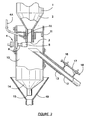
- Fig. 1 is a side elevational and schematic view, partly in cross-section, of an embodiment of the apparatus in accordance with the present invention
- Fig. 2 is a cross sectional view of part of the apparatus of Fig.1
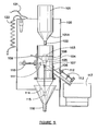
- Figs. 3 to 5 are side elevational and schematic views, partly in cross-section, of an apparatus in accordance with another aspect of the invention
- Fig. 6 is a cross-sectional view of part of the apparatus of Figs. 3 to 5
- Fig. 7 shows an electrical circuit for use in the apparatus of the invention.
- a first hopper 1 for housing a replenishable supply of a welding material in particulate form.
- An initial charge of particulate material of generally selected size is added through the top of first hopper 1.
- first hopper 1 is substantially funnel-shaped having a conical discharge chute 2 at its lower end.
- Numeral 3 relates to a centrally disposed open tube at the bottom of chute 2.
- a gate means 4 comprising a piston 6 and a closure means 5 may be used, closure means 5 being moved into and out of co-operation with centrally disposed open tube 3.
- Item 4A refers to means for cleaning open tube 3 by the use of a jet of compressed gas, such as compressed air.
- Numeral 1A refers to a collet or collets insertable into centrally disposed open tube 3 to further control flow of the particulate material.
- Second hopper 10 is disposed immediately below first hopper 1 and is adapted to retain for a time particulate material exiting from first hopper 1.
- Means to extract or "take-off" means) a proportion of the flow of particulate material is provided in co-operation with second hopper 10. This proportionate flow is recycled to preliminary hopper 20.
- This means to extract is exemplified in Fig.2 . by an elongate hollow member 12 slidable in a fixed sleeve 13 which penetrates side wall 11 of second hopper 20.
- Elongate hollow member 12 is shaped to penetrate the flow of particulate material emerging from centrally disposed open tube 3.
- elongate hollow member 12 is advanced or retracted using arm members 16 and 17 attached to sleeve 13 and elongate hollow member 12 respectively. Movement of elongate hollow member 12 may be obtained using a screw member 18 penetrating arm members 17 and 18 respectively.
- a proportion of particulate material is recycled to preliminary hopper 20 by means of return by-pass hose 19.
- a semi-circular deflector tube 19A preferably made of tungsten or a tungsten alloy, is fitted to the end of by-pass hose 19, internally of preliminary hopper 20.
- This deflector tube 19A ends in a deflector plate 19B at a right angle to the axis of the tube.
- a vacuum shut-off ball 21 is fitted within cage 22 at the bottom of return storage cone 23.
- a screening filter 24 is fitted to the upper outlet of preliminary hopper 20 to capture all but very fine dust.
- injection tube 50 carries a wire feed for a MIG torch.
- Injection tube 51 also carries argon gas to bathe the weld pool.
- An adjustable tie means 52 is also shown whereby the relative angles of attack of injection tubes 50 and 51 may be altered as well as their relative distances from the weld pool.
- numeral 100 indicates a back plate to which the operative part of the invention is attached.
- Item 101 is a first hopper which terminates in conical discharge chute 101A and tube 102.
- Numeral 103 indicates a spacing nut, numeral 104 a nut and numeral 105 a second opposing spacing nut.
- Item 106 is a spring.
- Numeral 107. indicates a second hopper and numeral 108 a transverse, circular, interior plate within the hopper 107.
- Item 109 is means for cleaning an aperture through spacing nut 104 and spacing nut 105.
- Numeral 110 indicates a piston supplied with closure means 111 for opening and closing the aperture through spacing nut 105 by means of compressed air.
- Item 112 indicates an elongated hollow member which can be advanced or retracted using threaded arm mechanism 113, as previously described.
- Item 114 is a conical discharge chute, item 115 a discharge tube and item 116 a funnel.
- Numeral 117 indicates a reservoir for particulate material.
- Item 118 is a tube for compressed air leading to means for cleaning 109.
- Item 119 and item 120 are a pair of tubes for compressed air for operating piston 110.
- Numeral 121 indicates an electrical lead for operating a switch to in turn operate a feed of compressed to pair of tubes 119 and 120.
- Item 122 indicates a supply tube for compressed air.
- Item 123 is an electrical inlet and item 124 is a time meter.
- Fig.4 is essentially the same as Fig.3 ., the differences being that only hidden parts are shown with dotted lines and connecting tubes for compressed air are omitted.
- Fig.5 is essentially the same as Figs.3 and 4 , the difference being that the springs (one only is shown) are elongated to allow cleaning of conical discharge chute 114 and funnel 116.
- Fig.6 shows the lower portion of first hopper 101 connected to second hopper 107 suspended above funnel 116.
- First hopper 101 terminates in a tube 102 which is provided with an exterior thread 102A which co-operates with internal thread 102B on spacing nut 103, nut 104 and spacing nut 105.
- Elongated hollow member 112 is shown in partial cross-section.
- Fig.7 shows an electrical circuit for operating various facets of the invention and determining how long the apparatus has been in use.
- 240 volts is supplied to a power filter 201 and then to a transformer 202 where it emerges as 24 volts.
- a relay switch 203 is supplied in the circuit.
- a timing motor 204 is inserted in parallel to measure how long the circuit has been in use and hence how long welding has taken.
- An air solenoid coil 205 is inserted in parallel in the circuit to operate the closure means between the first hopper and the second hopper.
- air solenoid coil 205 operates a mechanical switch (not shown) which in turn operates the closure means between the first hopper and the second hopper.
- a vacuum motor 206 which is connected to the preliminary hopper to remove particulate fines.
- a capacitor 207 of approximately 10 microfarads is connected around the vacuum motor 206 to stop arcing by bleeding back voltage. It also suppresses noise.
- the circuit means further comprises a sub-circuit which supplies 12 volts to a foot switch 108 and a relay coil 209.
- the object of this sub-circuit is to allow switch 203 to be opened and closed by the use of a safe voltage. Conveniently switch 208 is foot-operated.
- the variant of the present invention which uses a preliminary hopper to assist recycling may be awkward to use in cases where there is limited space or the weld is to be placed vertically.
- the simpler variant may well be desirable in such situations.
Landscapes
- Physics & Mathematics (AREA)
- General Physics & Mathematics (AREA)
- Engineering & Computer Science (AREA)
- Automation & Control Theory (AREA)
- Fluid Mechanics (AREA)
- Filling Or Emptying Of Bunkers, Hoppers, And Tanks (AREA)
- Feeding, Discharge, Calcimining, Fusing, And Gas-Generation Devices (AREA)
- Processing And Handling Of Plastics And Other Materials For Molding In General (AREA)
Claims (10)
- Vorrichtung zur dosierten Abgabe eines partikelförmigen Schweißmaterials, wobei die Vorrichtung umfasst:(a) einen ersten Behälter (1), der eine erste Einlasseinrichtung und eine erste Auslasseinrichtung (2, 3) hat, die eine zentral-angeordnete offene Röhre (3) hat;(b) einen zweiten Behälter (10) in Strömungsverbindung mit dem ersten Behälter, der eine zweite Einlasseinrichtung und eine zweite Auslasseinrichtung (14, 15) hat;(c) eine Abnahmeeinrichtung (12, 13) in Kombination mit dem zweiten Behälter und die angepasst ist, einen Anteil des partikelförmigen Materials von einem Strom des Materials über den zweiten Behälter zu entfernen; und(d) eine Recyclingeinrichtung (19), die eingerichtet ist, den entsprechenden Strom des partikelförmigen Materials zum ersten Behälter zurückzubringen,
dadurch gekennzeichnet, dass
eine Drosseleinrichtung (1A) in die erste Auslasseinrichtung (2, 3) eingefügt ist, um den Strom des partikelförmigen Materials zu beschränken, indem der Venturi-Effekt in dem Bereich der zentral-angeordneten offenen Röhre geändert wird. - Vorrichtung nach Anspruch 1, wobei der erste Behälter in einer konischen Entlade-Schütte (2, 3) endet und die Beschränkungseinrichtung eine oder mehrere einer Reihe an Konushülsen (1A) umfasst, welche in den Boden der konischen Entlade-Schütte (3) eingefügt ist/sind, um den Venturi-Effekt zu ändern, um die Auslassrate des partikelförmigen Materials vom ersten Behälter zu steuern.
- Vorrichtung nach Anspruch 1, wobei die Vorrichtung außerdem einen Vor-Behälter (20) in Stömungsverbindung mit dem ersten Behälter aufweist, wobei eine Abtenkeinrichtung (19A, 19B) in den Vor-Behälter eingefügt ist, um sicherzustellen, dass eine relativ hoher Anteil des Mediums bis zu einer großen Partikelmaterialgröße zu dem ersten Behälter durchgelassen wird.
- Vorrichtung nach Anspruch 3, wobei ein Sieb-Filter (24) am oberen Auslass des Vor-Behälters eingepasst ist, um sicherzustellen, dass lediglich feiner Staub von dem System extrahiert wird.
- Vorrichtung nach einem der Anspräche 1 bis 4, wobei die Vorrichtung außerdem umfasst:einen Partikel-Schweißmaterial-Tank (117) von der Abnahmeeinrichtung, von welchem das Material in ausgewählten Intervallen in den ersten Behälter recycelt werden kann.
- Vorrichtung nach einem der Anspräche 1 bis 5 in Kombination mit einer Schweißvorrichtung (50-52), welche eine Schweißeinspritzröhre (50) aufweist, welche mit der zweiten Auslasseinrichtung verbunden ist, wobei die Schweißeinspritzröhre in einem optimalen Winkel zur Horizontalen angeordnet ist, wodurch:(a) das partikelförmige Schweißmaterial hinter den Abbrennbereich fällt, verursacht durch Zündung des Schweißdrahts (51); und(b) das partikelförmige Schweißmaterial nicht so weit von dem Abbrennbereich fällt, dass kein Schweißbecken gebildet wird.
- Verbessertes Verfahren für die dosierte Verteilung eines partikelförmigen Schweißmaterials unter Verwendung der Vorrichtung nach einem der Ansprüche 1 bis 6, wobei das Verfahren folgende Schritte umfasst:(a) Einrichten des Primärstroms des Materials durch den ersten Behälter und den zweiten Behälter der Reihe nach;(b) Extrahieren - vom Primärstrom über den zweiten Behälter - eines bestimmten Sekundärstroms des Materials durch die Abnahmeeinrichtung; und(c) Recyceln des Sekundärstroms zum Primärstrom in einer Weise, dass eine dosierte Abgabe des Materials erlangt wird,wobei die Verbesserung die Verwendung der Beschränkungseinrichtung umfasst, um den Primärstrom einzustellen, um den entsprechenden Strom durch den ersten Behälter in einer Weise zu erlangen, dass eine gewünschte Bereichsgröße an partikelförmigem Material geliefert wird.
- Verfahren nach Anspruch 7, wobei die Einstellung des Primärstroms durch Einfügen von einer oder mehreren Konushülsen (1A) in den ersten Auslass erreicht wird, um ein vorher festgelegtes Ausmaß des Stroms an partikelförmigem Material vom ersten Behälter zu beschränken.
- Verfahren nach Anspruch 7 oder 8, wobei das partikelförmige Material Schweißmaterial ist, welches feines Material und grobes Material umfasst, und der recycelte Strom des partikelförmigen Schweißmaterials zum Vor-Behälter (20) in Strömungsverbindung mit dem ersten Behälter durchgelassen wird, in welchem das feine Material im Vor-Behälter nach oben zu einer Sammelkammer durchgelassen wird und das grobe Material nach unten zum ersten Behälter durchgelassen wird.
- Verfahren nach Anspruch 9, welches außerdem das teilweise Durchlassen des vorbestimmten Sekundärstroms zu einem Tank (117) für das partikelförmige Schweißmaterial umfasst, wobei von dem Tank das partikelförmige Schweißmaterial in ausgewählten Intervallen in den ersten Behälter recycelt wird.
Applications Claiming Priority (5)
| Application Number | Priority Date | Filing Date | Title |
|---|---|---|---|
| AU2002953139 | 2002-12-04 | ||
| AU2002953139A AU2002953139A0 (en) | 2002-12-04 | 2002-12-04 | Method and apparatus for the dispensing of a particulate material |
| AU2003905790 | 2003-10-22 | ||
| AU2003905790A AU2003905790A0 (en) | 2003-10-22 | Apparatus for the dispensing of a particulate material | |
| PCT/AU2003/001610 WO2004050509A1 (en) | 2002-12-04 | 2003-12-02 | Method and apparatus for dispensing of particulate material |
Publications (3)
| Publication Number | Publication Date |
|---|---|
| EP1597170A1 EP1597170A1 (de) | 2005-11-23 |
| EP1597170A4 EP1597170A4 (de) | 2006-03-08 |
| EP1597170B1 true EP1597170B1 (de) | 2009-10-07 |
Family
ID=32471019
Family Applications (1)
| Application Number | Title | Priority Date | Filing Date |
|---|---|---|---|
| EP03781995A Expired - Lifetime EP1597170B1 (de) | 2002-12-04 | 2003-12-02 | Verfahren und vorrichtung zur ausgabe von partikelförmigem material |
Country Status (6)
| Country | Link |
|---|---|
| EP (1) | EP1597170B1 (de) |
| AT (1) | ATE444920T1 (de) |
| AU (2) | AU2003289748A1 (de) |
| DE (1) | DE60329631D1 (de) |
| NZ (1) | NZ541003A (de) |
| WO (1) | WO2004050509A1 (de) |
Families Citing this family (3)
| Publication number | Priority date | Publication date | Assignee | Title |
|---|---|---|---|---|
| FR2914996A1 (fr) * | 2007-04-12 | 2008-10-17 | Hasler Internat Sa | Dispositif de mesure et de controle du debit d'un combustible pulverise pour alimenter une tuyere |
| IT201800005809A1 (it) * | 2018-05-29 | 2019-11-29 | Dosatore per materie plastiche granulari e simili provvisto di un sistema di pulizia delle tramogge | |
| IT201900018698A1 (it) * | 2019-10-14 | 2021-04-14 | Syncro S R L | Dosatore continuo per materie plastiche granulari e simili provvisto di un sistema di pulizia |
Family Cites Families (3)
| Publication number | Priority date | Publication date | Assignee | Title |
|---|---|---|---|---|
| DE9313779U1 (de) * | 1993-09-11 | 1993-11-18 | Rabewerk Gmbh + Co, 49152 Bad Essen | Landwirtschaftliche pneumatische Verteilmaschine |
| DE19538626A1 (de) * | 1995-09-15 | 1997-03-20 | Amazonen Werke Dreyer H | Landwirtschaftliche Verteilmaschine |
| AU753910B2 (en) * | 1999-10-01 | 2002-10-31 | T.A.C.A. International Pty Ltd | Metering dispenser |
-
2003
- 2003-12-02 DE DE60329631T patent/DE60329631D1/de not_active Expired - Lifetime
- 2003-12-02 EP EP03781995A patent/EP1597170B1/de not_active Expired - Lifetime
- 2003-12-02 WO PCT/AU2003/001610 patent/WO2004050509A1/en not_active Ceased
- 2003-12-02 AU AU2003289748A patent/AU2003289748A1/en not_active Abandoned
- 2003-12-02 AT AT03781995T patent/ATE444920T1/de not_active IP Right Cessation
- 2003-12-02 NZ NZ541003A patent/NZ541003A/en not_active IP Right Cessation
-
2010
- 2010-12-02 AU AU2010246574A patent/AU2010246574B2/en not_active Ceased
Also Published As
| Publication number | Publication date |
|---|---|
| EP1597170A4 (de) | 2006-03-08 |
| NZ541003A (en) | 2010-04-30 |
| ATE444920T1 (de) | 2009-10-15 |
| AU2010246574A1 (en) | 2010-12-23 |
| EP1597170A1 (de) | 2005-11-23 |
| AU2010246574B2 (en) | 2012-02-16 |
| WO2004050509A1 (en) | 2004-06-17 |
| AU2003289748A1 (en) | 2004-06-23 |
| DE60329631D1 (de) | 2009-11-19 |
Similar Documents
| Publication | Publication Date | Title |
|---|---|---|
| AU2010246574B2 (en) | Method and apparatus for dispensing particulate material | |
| DE3788792T2 (de) | Verfahren und Vorrichtung zur Steuerung eines Schweissanordnung vom Kurzschlusstyp. | |
| DE10164735C2 (de) | Verfahren zur Aerosolerzeugung | |
| EP3600765B1 (de) | Wasser-abrasiv-suspensions-schneidanlage und verfahren zum wasser-abrasiv-suspensions-schneiden | |
| US20110168640A1 (en) | Gas bubble generation for coalescing | |
| EP2366485B1 (de) | Lichtbogenschweißgerät mit einem gesteuert gekühlten WIG-Brenner | |
| DE2834900A1 (de) | Vorrichtung zur einfuehrung von zusatzstoffen in einen strom geschmolzenen metalls | |
| EP0266309A2 (de) | Apparat zur Abscheidung von Fremdkörpern, insbesondere Metallteilen aus rieselfähigem Material | |
| DE4322345B4 (de) | Verfahren und Vorrichtung zum Ausscheiden von Metallteilen aus einem Materialstrom | |
| US4829724A (en) | Cutting abrasive feeder, demand type | |
| EP0293564B1 (de) | Verfahren zu Einführen von Spülgas in eine einen Schiebeverschluss aufweisende Ausgussöffnung metallurgischer Gefässe | |
| US4005806A (en) | Apparatus for injection of hygroscopic powders into a high pressure liquid stream | |
| ZA200504428B (en) | Method and apparatus for dispensing of particulatematerial | |
| DE19900655C1 (de) | Vorrichtung zur Erzeugung stetiger und beliebig starker Schüttgutströme | |
| DE19947822A1 (de) | Verfahren und Vorrichtung zur Abgabe von carbonisiertem Trinkwasser über einen Wasserhahn | |
| US2934632A (en) | Method of and apparatus for feeding magnetic welding powder to welding wire | |
| JPS58100974A (ja) | 潜弧溶接用フラツクスの送給量制御方法 | |
| CN217111658U (zh) | 一种自动取样器 | |
| DE3611577A1 (de) | Elektrostatische pulver-spruehpistole | |
| EP3181247B1 (de) | Zuführvorrichtung und verfahren zum zuführen von schüttgut in eine schneckenmaschine, wobei metallteile aus dem schüttgut entfernt werden | |
| AU753910B2 (en) | Metering dispenser | |
| EP1165896B1 (de) | Spülvorrichtung für toiletten | |
| US3399814A (en) | Powder feeder with rotary, axially movable flow controller | |
| DE68917094T2 (de) | Entgasungsvorrichtung für Form. | |
| DE19811132C2 (de) | Vorrichtung zum Abscheiden feiner Partikel aus einem grobe und feine Partikel enthaltenden, mittels eines Gasstroms geförderten Schüttgutstrom |
Legal Events
| Date | Code | Title | Description |
|---|---|---|---|
| PUAI | Public reference made under article 153(3) epc to a published international application that has entered the european phase |
Free format text: ORIGINAL CODE: 0009012 |
|
| 17P | Request for examination filed |
Effective date: 20050704 |
|
| AK | Designated contracting states |
Kind code of ref document: A1 Designated state(s): AT BE BG CH CY CZ DE DK EE ES FI FR GB GR HU IE IT LI LU MC NL PT RO SE SI SK TR |
|
| AX | Request for extension of the european patent |
Extension state: AL LT LV MK |
|
| A4 | Supplementary search report drawn up and despatched |
Effective date: 20060124 |
|
| DAX | Request for extension of the european patent (deleted) | ||
| 17Q | First examination report despatched |
Effective date: 20070806 |
|
| GRAP | Despatch of communication of intention to grant a patent |
Free format text: ORIGINAL CODE: EPIDOSNIGR1 |
|
| GRAS | Grant fee paid |
Free format text: ORIGINAL CODE: EPIDOSNIGR3 |
|
| GRAA | (expected) grant |
Free format text: ORIGINAL CODE: 0009210 |
|
| AK | Designated contracting states |
Kind code of ref document: B1 Designated state(s): AT BE BG CH CY CZ DE DK EE ES FI FR GB GR HU IE IT LI LU MC NL PT RO SE SI SK TR |
|
| REG | Reference to a national code |
Ref country code: GB Ref legal event code: FG4D |
|
| REG | Reference to a national code |
Ref country code: CH Ref legal event code: EP |
|
| REG | Reference to a national code |
Ref country code: IE Ref legal event code: FG4D |
|
| REF | Corresponds to: |
Ref document number: 60329631 Country of ref document: DE Date of ref document: 20091119 Kind code of ref document: P |
|
| PG25 | Lapsed in a contracting state [announced via postgrant information from national office to epo] |
Ref country code: SI Free format text: LAPSE BECAUSE OF FAILURE TO SUBMIT A TRANSLATION OF THE DESCRIPTION OR TO PAY THE FEE WITHIN THE PRESCRIBED TIME-LIMIT Effective date: 20091007 |
|
| PG25 | Lapsed in a contracting state [announced via postgrant information from national office to epo] |
Ref country code: SE Free format text: LAPSE BECAUSE OF FAILURE TO SUBMIT A TRANSLATION OF THE DESCRIPTION OR TO PAY THE FEE WITHIN THE PRESCRIBED TIME-LIMIT Effective date: 20091007 Ref country code: PT Free format text: LAPSE BECAUSE OF FAILURE TO SUBMIT A TRANSLATION OF THE DESCRIPTION OR TO PAY THE FEE WITHIN THE PRESCRIBED TIME-LIMIT Effective date: 20100208 Ref country code: FI Free format text: LAPSE BECAUSE OF FAILURE TO SUBMIT A TRANSLATION OF THE DESCRIPTION OR TO PAY THE FEE WITHIN THE PRESCRIBED TIME-LIMIT Effective date: 20091007 Ref country code: ES Free format text: LAPSE BECAUSE OF FAILURE TO SUBMIT A TRANSLATION OF THE DESCRIPTION OR TO PAY THE FEE WITHIN THE PRESCRIBED TIME-LIMIT Effective date: 20100118 |
|
| PG25 | Lapsed in a contracting state [announced via postgrant information from national office to epo] |
Ref country code: BE Free format text: LAPSE BECAUSE OF FAILURE TO SUBMIT A TRANSLATION OF THE DESCRIPTION OR TO PAY THE FEE WITHIN THE PRESCRIBED TIME-LIMIT Effective date: 20091007 Ref country code: AT Free format text: LAPSE BECAUSE OF FAILURE TO SUBMIT A TRANSLATION OF THE DESCRIPTION OR TO PAY THE FEE WITHIN THE PRESCRIBED TIME-LIMIT Effective date: 20091007 |
|
| PG25 | Lapsed in a contracting state [announced via postgrant information from national office to epo] |
Ref country code: DK Free format text: LAPSE BECAUSE OF FAILURE TO SUBMIT A TRANSLATION OF THE DESCRIPTION OR TO PAY THE FEE WITHIN THE PRESCRIBED TIME-LIMIT Effective date: 20091007 Ref country code: EE Free format text: LAPSE BECAUSE OF FAILURE TO SUBMIT A TRANSLATION OF THE DESCRIPTION OR TO PAY THE FEE WITHIN THE PRESCRIBED TIME-LIMIT Effective date: 20091007 Ref country code: MC Free format text: LAPSE BECAUSE OF NON-PAYMENT OF DUE FEES Effective date: 20100701 Ref country code: BG Free format text: LAPSE BECAUSE OF FAILURE TO SUBMIT A TRANSLATION OF THE DESCRIPTION OR TO PAY THE FEE WITHIN THE PRESCRIBED TIME-LIMIT Effective date: 20100107 Ref country code: RO Free format text: LAPSE BECAUSE OF FAILURE TO SUBMIT A TRANSLATION OF THE DESCRIPTION OR TO PAY THE FEE WITHIN THE PRESCRIBED TIME-LIMIT Effective date: 20091007 |
|
| PLBE | No opposition filed within time limit |
Free format text: ORIGINAL CODE: 0009261 |
|
| STAA | Information on the status of an ep patent application or granted ep patent |
Free format text: STATUS: NO OPPOSITION FILED WITHIN TIME LIMIT |
|
| PG25 | Lapsed in a contracting state [announced via postgrant information from national office to epo] |
Ref country code: CZ Free format text: LAPSE BECAUSE OF FAILURE TO SUBMIT A TRANSLATION OF THE DESCRIPTION OR TO PAY THE FEE WITHIN THE PRESCRIBED TIME-LIMIT Effective date: 20091007 Ref country code: SK Free format text: LAPSE BECAUSE OF FAILURE TO SUBMIT A TRANSLATION OF THE DESCRIPTION OR TO PAY THE FEE WITHIN THE PRESCRIBED TIME-LIMIT Effective date: 20091007 |
|
| 26N | No opposition filed |
Effective date: 20100708 |
|
| PG25 | Lapsed in a contracting state [announced via postgrant information from national office to epo] |
Ref country code: GR Free format text: LAPSE BECAUSE OF FAILURE TO SUBMIT A TRANSLATION OF THE DESCRIPTION OR TO PAY THE FEE WITHIN THE PRESCRIBED TIME-LIMIT Effective date: 20100108 |
|
| PG25 | Lapsed in a contracting state [announced via postgrant information from national office to epo] |
Ref country code: IT Free format text: LAPSE BECAUSE OF FAILURE TO SUBMIT A TRANSLATION OF THE DESCRIPTION OR TO PAY THE FEE WITHIN THE PRESCRIBED TIME-LIMIT Effective date: 20091007 |
|
| PG25 | Lapsed in a contracting state [announced via postgrant information from national office to epo] |
Ref country code: LU Free format text: LAPSE BECAUSE OF NON-PAYMENT OF DUE FEES Effective date: 20091202 |
|
| PG25 | Lapsed in a contracting state [announced via postgrant information from national office to epo] |
Ref country code: HU Free format text: LAPSE BECAUSE OF FAILURE TO SUBMIT A TRANSLATION OF THE DESCRIPTION OR TO PAY THE FEE WITHIN THE PRESCRIBED TIME-LIMIT Effective date: 20100408 |
|
| PG25 | Lapsed in a contracting state [announced via postgrant information from national office to epo] |
Ref country code: TR Free format text: LAPSE BECAUSE OF FAILURE TO SUBMIT A TRANSLATION OF THE DESCRIPTION OR TO PAY THE FEE WITHIN THE PRESCRIBED TIME-LIMIT Effective date: 20091007 |
|
| PG25 | Lapsed in a contracting state [announced via postgrant information from national office to epo] |
Ref country code: CY Free format text: LAPSE BECAUSE OF FAILURE TO SUBMIT A TRANSLATION OF THE DESCRIPTION OR TO PAY THE FEE WITHIN THE PRESCRIBED TIME-LIMIT Effective date: 20091007 |
|
| REG | Reference to a national code |
Ref country code: FR Ref legal event code: PLFP Year of fee payment: 13 |
|
| PGFP | Annual fee paid to national office [announced via postgrant information from national office to epo] |
Ref country code: DE Payment date: 20160210 Year of fee payment: 13 Ref country code: IE Payment date: 20160218 Year of fee payment: 13 Ref country code: CH Payment date: 20160217 Year of fee payment: 13 |
|
| PGFP | Annual fee paid to national office [announced via postgrant information from national office to epo] |
Ref country code: GB Payment date: 20160217 Year of fee payment: 13 Ref country code: FR Payment date: 20160210 Year of fee payment: 13 Ref country code: NL Payment date: 20160210 Year of fee payment: 13 |
|
| REG | Reference to a national code |
Ref country code: DE Ref legal event code: R119 Ref document number: 60329631 Country of ref document: DE |
|
| REG | Reference to a national code |
Ref country code: CH Ref legal event code: PL |
|
| REG | Reference to a national code |
Ref country code: NL Ref legal event code: MM Effective date: 20170101 |
|
| GBPC | Gb: european patent ceased through non-payment of renewal fee |
Effective date: 20161202 |
|
| PG25 | Lapsed in a contracting state [announced via postgrant information from national office to epo] |
Ref country code: NL Free format text: LAPSE BECAUSE OF NON-PAYMENT OF DUE FEES Effective date: 20170101 |
|
| REG | Reference to a national code |
Ref country code: FR Ref legal event code: ST Effective date: 20170831 |
|
| REG | Reference to a national code |
Ref country code: IE Ref legal event code: MM4A |
|
| PG25 | Lapsed in a contracting state [announced via postgrant information from national office to epo] |
Ref country code: FR Free format text: LAPSE BECAUSE OF NON-PAYMENT OF DUE FEES Effective date: 20170102 Ref country code: CH Free format text: LAPSE BECAUSE OF NON-PAYMENT OF DUE FEES Effective date: 20161231 Ref country code: LI Free format text: LAPSE BECAUSE OF NON-PAYMENT OF DUE FEES Effective date: 20161231 |
|
| PG25 | Lapsed in a contracting state [announced via postgrant information from national office to epo] |
Ref country code: IE Free format text: LAPSE BECAUSE OF NON-PAYMENT OF DUE FEES Effective date: 20161202 Ref country code: GB Free format text: LAPSE BECAUSE OF NON-PAYMENT OF DUE FEES Effective date: 20161202 Ref country code: DE Free format text: LAPSE BECAUSE OF NON-PAYMENT OF DUE FEES Effective date: 20170701 |