EP1596539A1 - Device and method for correcting a path trouble in a communication network - Google Patents
Device and method for correcting a path trouble in a communication network Download PDFInfo
- Publication number
- EP1596539A1 EP1596539A1 EP04713173A EP04713173A EP1596539A1 EP 1596539 A1 EP1596539 A1 EP 1596539A1 EP 04713173 A EP04713173 A EP 04713173A EP 04713173 A EP04713173 A EP 04713173A EP 1596539 A1 EP1596539 A1 EP 1596539A1
- Authority
- EP
- European Patent Office
- Prior art keywords
- path
- backup
- backup path
- bandwidth
- node
- Prior art date
- Legal status (The legal status is an assumption and is not a legal conclusion. Google has not performed a legal analysis and makes no representation as to the accuracy of the status listed.)
- Granted
Links
Images
























Classifications
-
- H—ELECTRICITY
- H04—ELECTRIC COMMUNICATION TECHNIQUE
- H04J—MULTIPLEX COMMUNICATION
- H04J14/00—Optical multiplex systems
- H04J14/02—Wavelength-division multiplex systems
- H04J14/0287—Protection in WDM systems
- H04J14/0293—Optical channel protection
- H04J14/0295—Shared protection at the optical channel (1:1, n:m)
-
- H—ELECTRICITY
- H04—ELECTRIC COMMUNICATION TECHNIQUE
- H04J—MULTIPLEX COMMUNICATION
- H04J14/00—Optical multiplex systems
- H04J14/02—Wavelength-division multiplex systems
- H04J14/0278—WDM optical network architectures
- H04J14/0284—WDM mesh architectures
-
- H—ELECTRICITY
- H04—ELECTRIC COMMUNICATION TECHNIQUE
- H04J—MULTIPLEX COMMUNICATION
- H04J14/00—Optical multiplex systems
- H04J14/02—Wavelength-division multiplex systems
- H04J14/0287—Protection in WDM systems
- H04J14/0289—Optical multiplex section protection
- H04J14/0291—Shared protection at the optical multiplex section (1:1, n:m)
-
- H—ELECTRICITY
- H04—ELECTRIC COMMUNICATION TECHNIQUE
- H04L—TRANSMISSION OF DIGITAL INFORMATION, e.g. TELEGRAPHIC COMMUNICATION
- H04L45/00—Routing or path finding of packets in data switching networks
- H04L45/22—Alternate routing
-
- H—ELECTRICITY
- H04—ELECTRIC COMMUNICATION TECHNIQUE
- H04L—TRANSMISSION OF DIGITAL INFORMATION, e.g. TELEGRAPHIC COMMUNICATION
- H04L45/00—Routing or path finding of packets in data switching networks
- H04L45/24—Multipath
- H04L45/247—Multipath using M:N active or standby paths
-
- H—ELECTRICITY
- H04—ELECTRIC COMMUNICATION TECHNIQUE
- H04Q—SELECTING
- H04Q11/00—Selecting arrangements for multiplex systems
- H04Q11/0001—Selecting arrangements for multiplex systems using optical switching
- H04Q11/0062—Network aspects
-
- H—ELECTRICITY
- H04—ELECTRIC COMMUNICATION TECHNIQUE
- H04Q—SELECTING
- H04Q11/00—Selecting arrangements for multiplex systems
- H04Q11/0001—Selecting arrangements for multiplex systems using optical switching
- H04Q11/0062—Network aspects
- H04Q2011/0073—Provisions for forwarding or routing, e.g. lookup tables
-
- H—ELECTRICITY
- H04—ELECTRIC COMMUNICATION TECHNIQUE
- H04Q—SELECTING
- H04Q11/00—Selecting arrangements for multiplex systems
- H04Q11/0001—Selecting arrangements for multiplex systems using optical switching
- H04Q11/0062—Network aspects
- H04Q2011/0079—Operation or maintenance aspects
- H04Q2011/0081—Fault tolerance; Redundancy; Recovery; Reconfigurability
-
- H—ELECTRICITY
- H04—ELECTRIC COMMUNICATION TECHNIQUE
- H04Q—SELECTING
- H04Q11/00—Selecting arrangements for multiplex systems
- H04Q11/0001—Selecting arrangements for multiplex systems using optical switching
- H04Q11/0062—Network aspects
- H04Q2011/0088—Signalling aspects
Definitions
- the present invention relates to failure recovery of paths in a large-capacity path network.
- optical router management of an optical communication network is performed in a distributed manner for each node, and optical path connection setting is performed based on signaling processing between the nodes. That is, in an optical communication network using optical routers, setting and management of the optical paths are performed in an autonomous distributed manner for each node.
- a restoration method is promising.
- backup optical path bandwidth accommodated in a route completely different from an active optical path is kept, and the backup optical path bandwidth is shared with a backup optical path for restoring other active optical path. Accordingly, resources of backup optical paths required in a whole network for keeping a certain reliability can be reduced, so that the means is very effective.
- a principal objective is to implement a self-healing function in an ATM network, in which both an active virtual path (active VP) set in the ATM network and a backup virtual path (backup VP) for restoring the active virtual path are set before a failure occurs.
- active VP active virtual path
- backup VP backup virtual path
- the bandwidth of the backup VP various cases are conceivable such as a case where a same value as the bandwidth of the active VP is ensured or a case where a smaller value than the bandwidth of active VP is ensured. But, as for backup bandwidths that accommodate backup VPs defined for each link, the backup bandwidths are not necessarily set the same as a total sum of bandwidths of active VPs to be restored.
- An optical network is managed by dividing it into three layers that are an op (optical path) layer, an oms (optical multiplexed section) layer, and an ots (optical transmission section) layer.
- an op layer the oms layer and the ots layer, an op trail, an oms trail and an ots trail are defined, respectively.
- an optical channel corresponds to a wavelength bandwidth of an optical region defined between nodes, and corresponds to an op connection that accommodates the oms trail.
- the "channel" corresponds to a VC-3 (50 Mbit/s) or VC-4 (155 Mbit/s) bandwidth defined between cross-connect nodes.
- a method for managing the channels in units of one channel there are a method for managing the channels in units of one channel, and a method for managing in units of M channels.
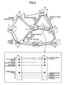
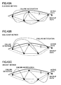
- Fig.3 shows the method for managing the backup channels in units of one channel.
- a backup system for three optical paths (1), (3) and (4) is registered so that 1-to-3 shared backup restoration is realized.
- the number of backup channels that are actually required is one third of active paths.
- each of active optical paths (3) and (4) enters in a state in which no backup bandwidth is kept in the section.
- backup path resources are kept again by performing new routing processing, and route change in the backup system occurs.
- Fig.4 shows the method for managing the backup channels in units of M channels.
- a backup channel group consists of two backup channels, and a backup system for five optical paths (1), (3)-(6) is registered so that 2-to-5 shared backup restoration is realized.
- the number of backup channels actually required is two fifths of actual paths in this example.
- each of other actual optical paths (3)-(6) can be restored by using a remaining one of the backup channels. That is, compared with the method for managing backup channels in units of one channel, it is possible to largely decrease frequency of occurrence of the process for keeping backup path resources again due to failure switching.
- the method for registering M backup channels for N optical paths is called a M : N shared restoration method.
- a similar technology is also applied to an ATM network in which virtual paths (VP) can be defined on a physical circuit, IP over MPLS in which a label switched path (LSP) can be defined, and Ether over MPLS network. That is, even though the bandwidth that is set for each active virtual path is switched to a backup route by the restoration method at the time when a link failure occurs, the necessary bandwidth set in the virtual path can be kept.
- VP virtual paths
- LSP label switched path
- a management control function for autonomously keeping a number of channels or bandwidths required for a channel group accommodating backup paths in units of link becomes important in order to reduce competing states in which a plurality of active paths that switch due to failure in a part of a network apparatus try to keep the same backup path bandwidth with each other.
- pre-assign restoration method For applying the restoration method to a network in which bandwidths of active paths need to be completely the same as bandwidths of backup paths like SDH paths and optical paths and the like, it is necessary to use "pre-assign restoration method" for keeping 100% bandwidth of backup SDH paths or optical paths beforehand. In the pre-assign restoration method, especially, it is required to quickly perform failure switching to a backup path having a long route length.
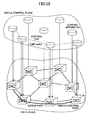
- the document 2 shows a network using optical routers in which a cross-connect technology based on high-reliability switches and a GMPLS (Generalized Multiple Protocol Label Switching) technology for realizing IP network-like distributed control are integrated.
- the network is configured such that a data plane and a control plane are clearly separated, wherein the data plane is formed by a switch function part for transferring user information of the communication network, and the control plane is formed by a control apparatus for transferring control signals of the communication network.
- the data plane is formed by a switch function part for transferring user information of the communication network
- the control plane is formed by a control apparatus for transferring control signals of the communication network.
- it is required to reduce disconnection of a normal path set in the data plane and unnecessary switching operations as bad influences due to failure of the control plane.
- a first object of the present invention is to provide, for realizing the shared restoration method, a backup path bandwidth keeping method for keeping bandwidth of backup paths and a path switching apparatus for realizing the method.
- a second object of the present invention is to provide, in a large capacity communication network autonomously controlled in a distributed way, a backup path bandwidth keeping method and a path switching apparatus that can dynamically keep a number of channels necessary for a channel group that accommodates backup paths so as to realize reliable failure recovery for a single link failure, and that can also flexibly support multiple link failure.
- a third object of the present invention is to provide, in a large capacity communication network that is autonomously controlled in a distributed way and that is virtually set on a link, a backup path bandwidth keeping method and a path switching apparatus that can dynamically keep a number of channels necessary for a channel group that accommodates backup paths so as to realize reliable failure recovery for a single link failure, and that can also flexibly support multiple link failure.
- a fourth object of the present invention is to provide a high-speed path switching method for performing failure recovery operations quickly in the shared restoration method, and to provide a path switching apparatus for realizing the method.
- a sixth object is to provide a path management apparatus that can perform failure recovery for multiple failures efficiently by performing distributed control.
- a seventh object of the present invention is to provide a network control apparatus that can reduce disconnection of a normal path set in the data plane and unnecessary switching operations as bad influences due to failure of the control plane.
- the first object of the present invention is achieved by the following invention.
- the present invention is a backup path bandwidth keeping method for keeping bandwidth of a backup path to which an active path is switched when the active path becomes unavailable in nodes of a communication network, wherein each node is connected to the same destination, and the method includes, as to M (M is a natural number equal to or less than L) channels in L (L is a natural number) channels that are kept as backup path bandwidth:
- the present invention can be also configured as a backup path bandwidth keeping method for keeping bandwidth of a backup path to which an active path is switched when the active path becomes unavailable in nodes of a communication network, wherein each node is connected to the same destination, M (M is a natural number equal to or less than L) channels in L (L is a natural number) channels kept as a backup path bandwidth are defined as a channel group, and identification number information for identifying the channel group is held, the method includes:
- the present invention can be also configured as a backup path bandwidth keeping method for keeping bandwidth of a backup path to which an active path is switched when the active path becomes unavailable in nodes of a communication network, wherein each node is connected to the same destination, M (M is a natural number equal to or less than L) channels in L (L is a natural number) channels kept as a backup path bandwidth are defined as a channel group, the method includes:
- the master node and the slave node are defined between two nodes adjacent to each other, and the method includes a master-slave check phase for determining one of the two nodes as the master node and the other as the slave node according to order of size of a node identification number assigned to each of the two nodes.
- information to be sent may include risk classification number information of links and nodes through which an active path corresponding to the backup path to be set passes.
- the identification information indicating that the channel group is a backup resource may include identification information to identify a failure service class.
- the backup channel group keeping phase may be invoked at the same time as the backup path bandwidth keeping phase, and at that time, the master node is a destination-side node existing at a destination side of the backup path, and the slave node is a source-side node existing at a source side of the backup path.
- the method may include a phase in which, as to the M channels kept as the backup path bandwidth, when it becomes necessary to exchange a channel in the M channels with another channel that is not kept as backup path bandwidth, at least identification number information of a new channel is recommended to a node at a destination of an opposite side of the channel.
- the present invention may be configured as a path switching apparatus including a path setting management function part for keeping bandwidth of a backup path to which an active path is switched when the active path that is set in a communication network becomes unavailable, wherein the path setting management function part is connected to the same destination, the switching apparatus including:
- the present invention may be configured as a path switching apparatus including a path setting management function part for keeping a bandwidth of a backup path to which an active path is switched when the active path that is set in a communication network becomes unavailable, wherein the path setting management function part is connected to the same destination, the switching apparatus including:
- the second object can be achieved by a backup path bandwidth keeping method for keeping bandwidth of a backup path to which an active path is switched when the active path becomes unavailable in nodes of a communication network, wherein each node is connected to the same destination, and channel identification number information of M (M is a natural number equal to or less than L) channels in L (L is a natural number) channels kept as backup path bandwidth are held, when assuming that n (n is a natural number) indicates a number of backup paths registered in a channel group in a link connecting two nodes, P(r) indicates a number of backup paths to be switched to any of the M channels when a switching operation from an active path to a backup path relating to a switching factor of a risk classification number r occurs, and that Max ⁇ P(r) ⁇ indicates a maximum value of P(r) for each risk classification number r, the number M of channels to be kept as the backup path bandwidth in the link is set such that M is equal to or greater than Max ⁇ P(r) ⁇ and equal to or less than n.
- the present invention can be also configured as a backup path bandwidth keeping method for keeping bandwidth of a backup path to which an active path is switched when the active path becomes unavailable in nodes of a communication network, wherein each node is connected to the same destination, M (M is a natural number equal to or less than L) channels in L (L is a natural number) channels kept as a backup path bandwidth are defined as a channel group, and identification number information for identifying each channel group are held, when assuming that n (n is a natural number) indicates a number of backup paths registered in a channel group in a link connecting two nodes, P(r) indicates a number of backup paths to be switched to the channel group when a switching operation from an active path to a backup path relating to a switching factor of a risk classification number r occurs, and that Max ⁇ P(r) ⁇ indicates a maximum value of the number P(r) for each risk classification number r, the number M of channels forming the channel group in the link is set such that M is equal to or greater than Max ⁇ P(
- the risk classification number is an identifying number for managing single link failure, single node failure as a risk component in the network, or a network domain as a complex of these. For example, a number ⁇ 1 ⁇ is assigned for a risk such as a link failure between a node A and a node B so as to manage the risk.
- the active path and the backup path are set such that the active path passes through links, nodes or network domains to which risk classification numbers that are different from those assigned for the backup path are assigned.
- the failure service class is defined based on reliability of each path. For example, when a failure occurs in a network, it may become temporarily impossible to keep connections for every path due to lack of an adequate amount of communication resources. In this case, by classifying the reliability of each path, efficient network operation can be realized. For example, the communication resource is assigned first to a path having a failure service class corresponding to high reliability, on a priority base. At the same time, it becomes possible to demand a price corresponding to the failure service class from a user who receives a communication service.
- the failure service class attribute information f may be set for each channel group in the link and for each backup path accommodated in the channel group, and a positive value a(f) corresponding to the failure service class attribute information f is defined, each backup path having the failure service class attribute information f is accommodated in the channel group having the same failure service class attribute information f, and the number M of channels forming the channel group of the failure service class attribute information f in the link is set to be equal to or greater than a(f) ⁇ Max ⁇ P(r) ⁇ and equal to or less than n when a (f) ⁇ Max ⁇ P(r) ⁇ is equal to or less than n, and is set to be equal to or less than n when a (f) ⁇ Max ⁇ P(r) ⁇ is greater than n.
- the present invention can be also configured as a path switching apparatus including a path setting management part for keeping a bandwidth of a backup path to which an active path is switched when the active path set in a communication network becomes unavailable, the path setting management function part including:
- the present invention can be also configured as a path switching apparatus including a path setting management part for keeping bandwidth of a backup path to which an active path is switched when the active path set in a communication network becomes unavailable, the path setting management function part including:
- Failure service class attribute information f may be set for each channel group in the link and for each backup path accommodated in the channel group, and a positive value a(f) corresponding to the failure service class attribute information f is defined, each backup path having the failure service class attribute information f is accommodated in the channel group having the same failure service class attribute information f, wherein the path setting management part includes a function for setting the number M of channels forming the channel group of the failure service class attribute information f in the link to be equal to or greater than a(f) ⁇ Max ⁇ P(r) ⁇ and equal to or less than n when a(f) ⁇ Max ⁇ P(r) ⁇ is equal to or less than n, and setting the number M to be equal to or less than n when a(f) ⁇ Max ⁇ P(r) ⁇ is greater than n.
- Path switching can be performed for each optical path conducting transmission between nodes by the wavelength division multiplexing scheme, or for each electrical path or each optical path conducting transmission between nodes by the time division multiplexing scheme.
- the third object of the present invention is achieved by the following invention.
- the present invention is a backup path bandwidth keeping method for keeping bandwidth of a backup path to which an active path is switched when the active path becomes unavailable in nodes of a communication network, wherein each node is connected to the same destination, and holds backup path bandwidth M (M ⁇ L) in backup path accommodating bandwidth L that is kept beforehand, when assuming that b indicates a total sum of backup path bandwidths registered in a VPI group in a link connecting two nodes, P(r) indicates a total sum of backup path bandwidths to be switched to any of the VPI group when a switching operation from an active path to a backup path relating to a switching factor of a risk classification number r occurs, and that Max ⁇ P(r) ⁇ indicates a maximum value of the backup path bandwidths P(r) for each risk classification number r, the bandwidth M to be kept as the backup path bandwidth in the link is set such that M is equal to or greater than Max ⁇ P(r) ⁇ and equal to or less than b.
- the present invention can be also configured as a backup path bandwidth keeping method for keeping bandwidth of a backup path to which an active path is switched when the active path becomes unavailable in nodes of a communication network, wherein each node is connected to the same destination, a backup path bandwidth M (M ⁇ L) in backup path accommodating bandwidth L kept beforehand is defined as a VPI group, and identification number information for identifying each VPI group is held, when assuming that b indicates a total sum of backup path bandwidths registered in the VPI group in a link connecting two nodes, P(r) indicates a total sum of backup path bandwidths to be switched to the VPI group when a switching operation from an active path to a backup path related to a switching factor of a risk classification number r occurs, and that Max ⁇ P(r) ⁇ indicates a maximum value of backup path bandwidths P(r) for each risk classification number r, the backup path bandwidth M forming the VPI group in the link is set such that M is equal to or greater than Max ⁇ P(r) ⁇ and equal to or less than b
- the VPI is an identifying number of a logical channel defined for accommodating a VP (virtual path), and is called Virtual Path Identifier.
- the VPI is defined for each link between nodes.
- Failure service class attribute information f may be set for each VPI group in the link and for each backup path accommodated in the VPI group, and a positive value a(f) corresponding to the failure service class attribute information f is defined, each backup path having the failure service class attribute information f is accommodated in the VPI group having the same failure service class attribute information f, and the backup path bandwidth M of the VPI group of the failure service class attribute information f in the link is set to be equal to or greater than a(f) ⁇ Max ⁇ P(r) ⁇ and equal to or less than n when a(f) ⁇ Max ⁇ P(r) ⁇ is equal to or less than n, and is set to be equal to or less than n when a(f) ⁇ Max ⁇ P(r) ⁇ is greater than n.
- the present invention can be also configured as a path switching apparatus including a path setting management part for keeping bandwidth of a backup path to which an active path is switched when the active path set in a communication network becomes unavailable, wherein each path switching apparatus is connected to the same destination, the path setting management function part holds backup path bandwidth M (M ⁇ L) in backup path accommodating bandwidth L kept beforehand, the path setting management function part including:
- the present invention can be also configured as a path switching apparatus including a path setting management part for keeping bandwidth of a backup path to which an active path is switched when the active path set in a communication network becomes unavailable, wherein each path switching apparatus is connected to the same destination, the path setting management function part including:
- Failure service class attribute information f may be set for each VPI group in the link and for each backup path accommodated in the VPI group, and a positive value a(f) corresponding to the failure service class attribute information f is defined, each backup path having the failure service class attribute information f is accommodated in the VPI group having the same failure service class attribute information f, and the path setting management function part includes:
- the fourth object of the present invention is achieved by the following invention.
- the present invention is a high-speed path switching method for activating a backup path to be switched from an active path when the active path becomes unavailable in nodes of a communication network, wherein:
- the present invention can be also configured as a path switching apparatus including a path setting management function part for keeping bandwidth of a backup path to which an active path is switched when the active path that is set in a communication network becomes unavailable, wherein the path setting management function part is connected to the same destination, the switching apparatus including:
- the path switching apparatus may further include:
- Path switching may be performed for each optical path transmitted between nodes by the wavelength division multiplexing scheme, for each electrical path or each optical path transmitted between nodes by the time division multiplexing scheme, or for each virtual electric path transmitted between nodes by the cell, frame or packet multiplexing scheme.
- the fifth object of the present invention can be achieved by the following invention.
- the present invention is a high-speed path switching method, including the steps of:
- the backup path may be set when a route length of the backup path exceeds a predetermined length or when a number of nodes through which the backup path passes exceeds a predetermined number, and in other cases, only bandwidth is kept for the backup path.
- the present invention can be also configured as a path switching apparatus for switching an active path set between two nodes in a communication network to a backup path set between the two nodes via a route different from that of the active path when the active path fails, the path switching apparatus including:
- the path switching apparatus may further include means for sending and receiving identification information indicating whether a backup path set between the own node and an adjacent node is the hot state backup path.
- the path switching apparatus may further include means for, when sending and receiving a switching message for switching the active path to the backup path via the backup path route at the time of failure of the active path, obtaining channel bandwidth information that accommodates the hot state backup path from the path management means and selecting a switching destination of the backup path so as to generate the switching message including the channel bandwidth.
- the path switching apparatus may further includes means for transferring a message along path switching apparatuses on the route of the hot state backup path for restoring the active path at the time of failure of the active path, wherein the message is for making settings such that the bandwidth of the hot state backup path is not released for failure recovery for other paths.
- the sixth object of the present invention can be achieved by the following invention.
- the present invention is a path management apparatus for keeping bandwidth (a channel) of a backup path to which an active path set in a communication network is switched when the active path becomes unavailable, and managing path connection and switching, the path management apparatus including:
- the notification means may be configured to perform the notification of the activation impossibility including information of activation impossibility for each node section through which the backup path passes.
- the notification means may be configured to add information of the activation impossibility of the backup path to a backup path management message that is transferred periodically for normality verification in a direction from a source node to a destination node of the backup path or in the reverse direction.
- the path management apparatus may further include channel diverting means for ascertaining that a backup path cannot keep a channel in another node section according to the notification of the activation impossibility, and diverting a channel assigned for accommodating the activation-impossible backup path to a channel for accommodating the other backup path.
- the present invention can be configured as a path management apparatus for keeping a channel of a backup path to which an active path set in a communication network is switched when the active path becomes unavailable, and managing path connection and switching, wherein plural channels for accommodating plural backup path groups are kept and shared, and a priority class is set for each backup path group, the path management apparatus including:
- the seventh object of the present invention can be achieved by the following invention.
- the present invention is a network control apparatus for controlling path management in a distributed manner for nodes in a communication network in which a data plane for transferring user information and a control plane for transferring control signals are separated, the network control apparatus including:
- the control link management function part may include a function for sending abnormality of a control link connected to own node to an adjacent node; and a function for sending abnormality of a control link information received from an adjacent node to another adjacent node.
- a communication network to which the backup path bandwidth keeping method of the present embodiment is applied is one shown in Fig.1.
- This communication network is an optical path network defining optical paths of wavelength units, and the communication network is formed by optical cross-connect nodes for realizing cross-connection of these optical paths.
- optical paths are defined in the nodes from the source node #1 to the destination node #8 in a point-to-point manner.
- the wavelength of the optical path is converted to avoid a collision with another optical path.
- the bandwidth of the optical path is 10 Gbit/s, for example, and transmission is performed with an OTN format conforming to the ITU-T G.709 specification.
- optical paths are accommodated in a fiber link at intervals of 50 GHz so that wavelength division multiplexing transmission of 32 wavelengths is realized in each fiber link.
- M op connections that are optical channels, in L op connections to be used as backup paths are bundled for the purpose of management so that the op connections are managed as an optical channel group.
- ⁇ indicates an interface of a fiber label
- ⁇ indicates an interface of a wavelength label
- ⁇ indicates an interface of a backup optical channel group label.
- An identification number is assigned not only to the optical path but also to the optical channel group. Then, keeping bandwidths for backup optical paths is performed by designating backup optical channel groups of each link.
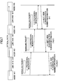
- Fig.7 is a figure showing a signaling sequence for setting an active optical path and a backup optical path in the backup path bandwidth keeping method of the embodiment 1-1.
- a RSVP-TE protocol For the signaling sequence of the active path, a RSVP-TE protocol is used.
- a Path message is sent from a source-side node to a destination-side node, so that resources necessary for setting the optical path are provisionally reserved in each node.
- resources that have been provisionally reserved are kept by using a Resv message from the destination-side node At that time risk classification number information of nodes and links through which the optical path passes is recorded and is reported to the source-side node.
- the source-side node performs route calculation for the backup optical path.
- the route calculation the risk classification number information of the active optical path that is reported by the above-mentioned Resv message is used, and the route of the backup optical path is determined under the constraint that the route does not pass through a node or a link having the risk classification number information.
- the risk classification number information is failure scenario number information assigned to a single node or a single link or to a set of nodes or links.
- the route of the backup optical path is determined such that a failure scenario the same as that of the active optical path is included.
- the concept of the "risk classification number" of the present embodiment is based on SRLG (Shared Risk Link Group (IETF Internet draft draft-ietf-ipo-framework-01.txt)).
- SRLG Shared Risk Link Group (IETF Internet draft draft-ietf-ipo-framework-01.txt)).
- the SRLG is a technology in which a failure of each link or node apparatus is managed as a scenario number, and a setting route of a backup line for restoring an active line is determined beforehand for each failure scenario.
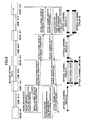
- Fig.8 is a figure showing a signaling sequence for setting the backup optical path of the embodiment 1-1.
- the RSVP-TE protocol is also used for the signaling sequence for the backup optical path.
- a Path message is sent from the source-side node to the destination-side node, so that resources necessary for setting the optical path are provisionally reserved for each node.
- the path message includes a backup identifier indicating that the message is for setting the backup optical path, and risk classification number information added to links and nodes through which the active path corresponding to the backup path passes. These pieces of information are stored in each node at which the resources are provisionally reserved.
- the provisionally reserved resources are "backup reserved” by using the Resv message from the destination-side node.
- “backup reservation” is performed by specifying an identification number of an optical channel group or an optical channel used as backup resources. Physical setting of optical switches is not mandatory in the backup reservation.
- the Resv message includes a backup optical channel group identifying number of a backup optical channel group that accommodates the backup optical path. The backup optical channel group identifying number is different for each link. In this embodiment, a channel group 2 is selected between nodes #7 and #8, a channel group 3 is selected between nodes #2 and #4, and a channel group 1 is selected between nodes #4 and #1.
- the Resv message sent from the node #2 to the node #1 includes optical channel group number information of optical channel groups selected in each link in addition to route information (passing node number information). By receiving the information; the node #1 (Ingress node) can ascertain the route and selected backup wavelength channel group numbers for the backup optical path.
- the method of this embodiment by sharing an optical channel as a backup optical path resource necessary for failure recovery of an active optical path, it becomes possible to decrease the necessary number of optical channels.
- the number of managed objects of backup optical channel resources can be largely decreased in the whole network. Further, frequency of re-keeping processes for the backup optical path resources due to occurrence of switching can be largely decreased.
- Each node has status of use of fiber links, identification information of active optical paths to be restored by each "backup reserved" optical channel group, and risk classification number information, through which links the active optical paths pass.
- the necessary number of optical channels that forms the optical channel group changes.
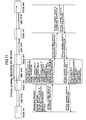
- Fig.9 shows a signaling sequence of the embodiment 1-2.
- a master node and a slave node are defined between two nodes adjacent to each other such that a node having a larger node identification number is determined to be the master node and a node having a smaller one is determined as the slave node. Or, the reverse may be applied.
- a slave node #2 that has detected a change of backup reservation state of the backup optical paths recommends to a master node #4 candidates of optical channels forming the optical channel group by using the Path message.
- the master node #4 selects optical channels (2, 3, 4 in this example) that are applicable for members of the optical channel group among from the recommended optical channels (1, 2, 3, 4), and notifies the slave node #2 of the result by using the Resv message.
- Deletion of an optical channel group may be performed when the number of optical channels that form the optical channel group becomes 0 or 1.
- the optical channel group that accommodates backup optical paths is autonomously maintained, established or deleted between adjacent nodes, and the present embodiment indicates a means for controlling optical channels that are members of the optical channel group in an autonomous distributing manner. According to that, the number of optical channels of the optical channel group that accommodates backup optical paths can be changed flexibly so that effective use of network resources and a high recovery rate for active optical path failure can be realized.
- Fig.10 shows a signaling sequence of the embodiment 1-3.
- the slave node #2 that has detected a change of backup reservation state of the backup optical paths recommends to the master node #4 candidates of optical channels forming the optical channel group by using the Path message.
- the slave node #2 also notifies the master node #4 of a failure service class of the optical channel group.
- the master node #4 selects optical channels (2, 3, 4 in this example) that are applicable for members of the optical channel group among from the recommended optical channels (1, 2, 3, 4), and notifies the slave node #2 of the result by using the Resv message.
- the master node #4 selects optical channels of the members in consideration of the failure service class of the optical channel group.
- the optical channel group that accommodates backup optical paths is autonomously maintained, established or deleted between adjacent nodes, and by defining the failure service class of the optical channel group, the number of optical channels that become members of the optical channel group can be increased or decreased according to the failure service class. That is, a high recovery rate can be realized by including many optical channels as members for a high service class.
- a modified example of the management control method of the optical channel group that is "backup reserved" in the embodiment 1-2 is shown.
- a method is shown in which the optical channel group and optical channels that form the optical channel group are autonomously established between adjacent nodes, wherein the establishment of the optical channel group and "backup reservation" of backup optical paths are performed at the same time.
- Fig.11 shows a signaling sequence of the embodiment 1-4.
- a source-side node that has detected a change of backup reservation state of the backup optical path at the same time when provisional reservation of the backup paths is performed recommends to a destination-side node candidates of optical channels forming the optical channel group by using a Path message.
- the destination-side node selects optical channels (2, 3, 4 in this example) that are applicable for members of the optical channel group among from the recommended optical channels (1, 2, 3, 4), and notifies the source-side node of the result by adding the result to the Resv message for establishing "backup reservation" of the backup optical paths.
- the optical channel group that is backup optical path resources necessary for failure recovery for active optical paths, can be established at the same time when setting the backup optical paths.
- the number of optical channels that are members of the optical channel group is lacking, the number of the optical channels of the optical channel group can be quickly increased by the method of this embodiment by using the setting request of the backup optical paths.
- "backup reservation" of the backup optical paths fails. But, processes in such a case can be also performed quickly so that backup optical path setting that uses a different route can be performed in a short time.
- optical (wavelength) path is described as an example as a physical medium of a path
- any one of VC-3 or VC-4 path of SONET/SDH a virtual path realized by setting a VPI identifier of ATM
- a label switch path realized by the MPLS technology e.g., a label switch path realized by the MPLS technology
- Ether path realized by a Tag-VLAN technology of the Ether can be used.
- the backup path bandwidth keeping method of the present invention as to M channels being kept as backup path bandwidths, when it becomes necessary to exchange a channel in the M channels with another channel that is not kept as backup path bandwidth due to a factor such as a failure of a transceiver, a phase for recommending at least identification number information of the new channel to a node at an opposite side destination of the new channel is added.
- Fig.12 is a block diagram of the path switching apparatus in the embodiment 1-5 of the present invention.
- the path switching apparatus of this embodiment is for realizing each embodiment of the above-mentioned backup path bandwidth keeping method.
- block diagrams of apparatuses that are shown hereinafter the same reference numerals are assigned to corresponding function parts.
- the path switching apparatus includes an optical switch part 10 for realizing cross-connection by each wavelength path, a management control function part 20 for managing and controlling it, and a channel management database 15.
- the optical switch part 10 includes an optical switch function part 11 and a switch control part 12 for controlling the optical switch function part 11.
- the optical switch part 10 of this embodiment uses a 128 ⁇ 128 switch and has a capacity for inputting and outputting four fiber links each multiplexing 32 waves of optical paths.
- a transmission speed of each optical path is 2.5 Gbit/s, and is terminated with a SONET OC-48 interface.
- Control links are formed by SONET OC-3 lines each having a transmission speed of 155 Mbit/s.
- the control signal is an OSPF/IS-IS protocol packet for obtaining a network topology of an optical router network, a RSVP-TE/CR-LDR protocol packet for setting and releasing an optical path between packet switches, or a LMP protocol packet for performing failure monitoring for each fiber link, for example.
- the management control function part 20 includes a function part for processing the control signal protocols, and includes a routing process function part (OSPF/IS-IS protocol process function) 21 for realizing setting / releasing /switching /routing of an optical path, a path setting management function part (RSVP-TE/CR-LDR protocol process function) 22 for performing setting /releasing signaling for an optical path, a control link management function past (LMP protocol process function) 23 for performing failure monitoring of a control link network in which control signals are transmitted, and an IP process part 24.
- OSPF/IS-IS protocol process function OSPF/IS-IS protocol process function
- RSVP-TE/CR-LDR protocol process function path setting management function part
- LMP protocol process function control link management function past
- the path setting management function part 22 includes a signaling process part 221 that is a core of the RSVP-TE protocol, an active path setting/deleting process function part 222, a backup path setting/deleting process function part 223, a backup path activation process part 224 and a path management database 225.
- the signaling process part 221 may be use a CR-LDP protocol.
- the active path setting/deleting process function part 222, the backup path setting/deleting process function part 223 and the backup path activation process part 224 are connected to the channel management database 15.
- the active path setting/deleting process function part 222 and the backup path setting/deleting process function part 223 are connected to the routing process function part 21.
- the active path setting/deleting process function part 222 and the backup path activation process part 224 are connected to the switch control part 12.
- the channel management database 15 has a data structure for defining and managing optical channel groups each bundling plural backup optical channels as resources for accommodating backup optical paths such that the optical channel management according to the management model of Fig.6 can be performed, and the channel management database 15 performs state monitoring for optical channels.
- the channel management database 15 includes an optical channel risk classification database that stores risk classification number information of the path switching apparatus and of each link connected to the path switching apparatus, and stores risk classification number information registered for optical channels or optical channel groups that are accommodated in the path switching apparatus.
- the backup path setting/deleting process function part 223 collectively manages M (M is a natural number equal to or less than L) channels as a channel group in L (L is a natural number) channels kept as bandwidths for accommodating backup paths to be connected to the same node.
- M is a natural number equal to or less than L
- L is a natural number
- an identification number is assigned for identifying each channel group, and the backup path setting/deleting process function part 223 selects optical channels that become members of the optical channel group, and outputs the identification information of the optical channels to a database by linking the identification information with the corresponding optical channel group identification number.
- the signaling process part 221 outputs a backup path activation signal communicated by an adjacent node to the backup path activation process part 224, and outputs a backup path activation signal from the backup path activation process part 224 to an adjacent node.
- the signaling process part 221 receives, from an adjacent path switching apparatus, identification number information of channels or a channel group to be kept when keeping backup path bandwidths, and identification information indicating that the paths are backup paths, the signaling process part 221 distributes the information to the backup path setting/deleting process function part 223.
- the backup path setting/deleting process function part 223 searches for an output port of the backup path by referring to a routing table of the routing process function part 21, and outputs identification number information of a channel or a channel group to be kept in an output side for the backup path to the signaling process part 221 so as to notify an adjacent node of the identification number information.
- the risk classification number information communicated from an adjacent path switching apparatus when keeping backup path bandwidths is processed in the same way.
- the risk classification number information input to the signaling process part 221 is input into the channel management database 15 via the backup path setting/deleting process function part 223, and is added to risk classification number information registered for the optical channel of the optical channel group to be kept for the backup optical path, and the identification number information and the risk classification number information of the optical channel or the optical channel group are communicated to an adjacent node.
- the backup optical path activation process part 224 inputs/outputs a backup path activation signal with an adjacent node via the signaling process part 221. In addition, the backup optical path activation process part 224 performs actual backup path activation processes to drive the switch.
- the routing process function part 21 collects statuses of links connected to the own node by using the control link management function part 23 and the channel management database 15. Next, the routing process function part 21 sends the collected link information to other adjacent nodes via the IP process part 24. At the same time, all link information received by each of the adjacent nodes are sent to the routing process function part 21 from each of the adjacent nodes. Based on the results, Next Hop information for routing optical paths to each node in the network is generated.
- the Next Hop information to be generated has the following data structure: Node ID Output IF 10.10.105.1 IF 1 10.10.105.2 IF 2 10.11.106.2 IF 1
- This information means that, for example, it is instructed to connect an optical path from TF 1 in order to open the optical path to a node of 10.10.105.1.
- Each of the active path setting/deleting process function part 225 and the backup path setting/deleting process function part 223 searches Next Hop information held in the routing process function part 21 on the basis of destination node ID information of an optical path included in a Path message sent from a source-side node, and sends the Path message to a searched output IF via the signaling process part 221 and the IP process part 24 to a destination-side node.
- the signaling process part 221 adds its own Node ID information when sending the Path message. Accordingly, when returning the Resv message from the destination node to the source node, it becomes possible to pass the Resv message through each node that sent the Path message.
- the active path/backup path generated through such processes is stored in the path management database 225.
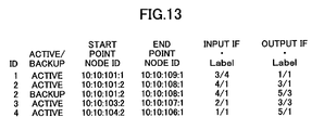
- the path management database 225 stores information with a data structure shown in Fig.13.
- one backup path is set in the node, and the backup path is a backup path for an active path 2.
- the node having this path management database 225 has an ID of 10:10:101:2 or 10:10:108:1, the node is a terminal point of the active path and the backup path (that is, the node is a point at which an switching operation for switching to the backup path is performed when a failure occurs in the active path).
- a failure notification information detected in the optical switch part 10 is transferred to the backup path activation process part 224.
- information of a path for which failure switching should be performed is searched for from the path management database 225. From the searched path information, it is determined whether to send a failure switching instruction.
- a backup optical path activation instruction is communicated via the signaling process part 221 and the IP process part 24 along a backup path route reserved beforehand.
- Fig.14 is a block diagram of a path switching apparatus in the embodiment 1-6 of the present invention.
- the path switching apparatus of this embodiment includes an electrical switch part 30 instead of the optical switch part 10 of the embodiment 1-6.
- the electrical switch part 30 includes an electrical switch function part 31, a switch control part 32 for controlling the electrical switch function part 31, and a digital cross-connect interface (DCC-IF) 33 for exchanging a control signal with the management control function part 20, and realizes a 32 ⁇ 32 digital cross-connection for SONET OC-48 links.
- DCC-IF digital cross-connect interface
- the control link is formed by using the DCC channel of the SONET OC-48.
- the control signals are, for example, a OSPF/IS-IS protocol packet for obtaining a network topology, a RSVP-TE/CR-LDR protocol packet for setting/releasing a path set between packet switches, and a LMP protocol packet for performing failure monitoring of each fiber link.
- a configuration of the management control function part 20 is the same as that of the embodiment 1-5. In this embodiment, it manages and controls VC-4 (155 M bit/s) channels defined in SONET instead of an optical channel.
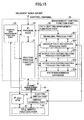
- Fig.15 is a block diagram of a path switching apparatus in the embodiment 1-7 of the present invention.
- the path switching apparatus of this embodiment includes an electrical switch part 40 instead of the optical switch part 10 of the embodiment 1-5.
- the electrical switch part 40 includes a cell switch function part 41, a switch control part 42 for controlling the cell switch function part 41, and a control signal interface (IP over ATM) 43 for exchanging a control signal with the management control function part 20, and can accommodate 32 input/output SONET OC-48 links, and realizes cell switching among them.
- IP over ATM control signal interface
- the control link is formed by using a common signaling network of a communication carrier.
- the control signals are, for example, a OSPF/IS-IS protocol packet for obtaining a network topology, a RSVP-TE/CR-LDR protocol packet for setting/releasing a path set between packet switches, and a LMP protocol packet for performing failure monitoring of each fiber link.
- the configuration of the management control function part 20 is the same as that of the embodiment 1-5.
- the management control function part 20 manages and controls VPIs defined between ATM switches.
- the VPI defined for each link between nodes corresponds to a channel that accommodates an optical path or an electrical path. That is, as shown in the figure, to correlate VPIs between input and output in each node apparatus corresponds to a cross-connection operation of an optical path or an electrical path.
- This embodiment can be applied to a label switch router that can provide a virtual path for IP packet traffic by using layer 2.5 MPLS technology, and this embodiment can be also applied to an Ether over MPLS switch that can provide a virtual path for an Ether frame in the same way.
- a necessary number of channels can be decreased by sharing the channels as backup path resources necessary for failure recovery of active paths in a network in which path bandwidths are set in a dispersed or fixed manner and it is required that bandwidths of active paths completely agree with bandwidths of backup paths.
- Fig.16 shows a configuration example of a path switching apparatus of the embodiment 2-1. This configuration is the same as that of the path switching apparatus of the embodiment 1-5.
- the path switching apparatus of the embodiment 2-1 includes an optical switch part 10 for realizing cross-connection by each wavelength path, a management control function part 20 for managing and controlling it, and a channel management database 15.
- the optical switch part 10 includes an optical switch function part 11 and a switch control part 12 for controlling the optical switch function part 11.
- the routing process function part 21 has a function for defining a cost for each fiber link, and searches for a route for which a fiber link cost accumulated between a source node and a destination node of an optical path to be established is the smallest. Dijkstra's algorithm can be applied for the search algorithm.
- backup optical path setting can be performed only by designating, for each link, an optical channel group that accommodates backup optical paths.
- the apparatus can control itself such that an active optical path is not set as an optical channel forming the optical channel group accommodating backup optical paths. Accordingly, each node can set an optical channel to be "backup reserved" as a backup resource for each link in an autonomous and distributed manner.
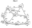
- Fig.17 shows a configuration example of an optical communication network to which the present embodiment is applied.
- a bandwidth is kept in nodes #1 - #3 - #6 - #8 as an active path, then, an optical path is opened along the route.
- a bandwidth is only reserved in nodes #1 - #2 - #4 - #7 - #8 as a backup optical path, and actual connection setting is not performed until the active optical path is disconnected due to a certain failure for the active optical path.
- risk classification number information that is assigned to the active optical path corresponding to the accommodated backup optical path is recorded.
- ⁇ 12, 18, 21 ⁇ is assigned as the risk classification number information that is a failure scenario of the route of the active optical path.
- the risk classification number information ⁇ 12, 18, 21 ⁇ is attached as attribute information of the optical channel group that accommodates the backup optical path for the active optical path.
- the risk classification number information is communicated to nodes one by one from a source-side node to a destination-side node when setting the backup optical path. Each node registers the risk classification number information in the channel management database 15 via its own signaling process part 221.
- the risk classification number information is associated with identification number information of the optical channel group that accommodates the backup optical path, and is stored in the channel management database 15 in every node on the backup optical path route.
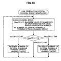
- Fig.18 shows a backup path setting process sequence in the backup path setting/deleting process function part 223 according to the embodiment 2-1.
- a number of backup optical paths registered in an optical channel group is n
- a number of backup optical paths to be switched to the optical channel group when a switching operation from active optical paths to backup optical paths is P(r) for the switching factor of a risk classification number r
- a maximum value of the backup optical path number P(r) obtained for the risk classification number r is Max ⁇ P(r) ⁇
- the backup path setting/deleting process function part 223 sends, to the signaling process part 221, a command for setting a number M of optical channels forming the optical channel group to be equal to or larger than Max ⁇ P(r) ⁇ and equal to or smaller than n.
- the number M of the optical channels forming the optical channel group is smaller than Max ⁇ P(r) ⁇ , the number of the optical channels is increased, if the number M of the optical channels forming the optical channel group is larger than Max ⁇ P(r) ⁇ , the number of the optical channels is decreased; if they are the same, no process is performed.
- setting of the backup optical paths is performed in consideration of the risk classification number information assigned to the active optical path.
- a necessary number of optical channels can be kept while checking the number of the optical channels that forms the channel group whenever necessary.
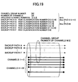
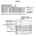
- the optical channel group there are three backup optical paths A, B and D to be switched to the optical channel group when a single failure of a risk classification number ⁇ 12 ⁇ occurs.
- the three optical channels are not enough for restoring all current optical paths for the risk classification number ⁇ 12 ⁇ .
- one optical channel is increased in the optical channel group (a channel 4 is added from idle channels in Fig.20), so that the channel group is formed by four optical channels. Accordingly, 100 % recovery can be realized for a single failure for the four optical paths that pass through a link of the risk classification number ⁇ 12 ⁇ .
- the backup optical path is set in consideration of risk classification number information added to the active optical path, so that backup optical path resources can be reduced as much as possible while realizing 100 % recovery for a single failure.
- an optical channel that belongs to the optical channel group can be dynamically added/deleted.
- attribute information of failure service classes is added to the optical channel group that accommodates the backup optical paths.
- Fig.21 shows a backup path setting process sequence of the backup path setting/deleting process function part 223 in the embodiment 2-2.
- limitations are applied in processes such that only a backup optical path for an active optical path of a failure service class the same as (or equal to or lower than) a failure service class held by the optical channel group is accommodated in the optical channel group.
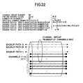
- the embodiment 2-2 if the current five optical channels are decreased by one or two for the three optical paths that pass through the link of the risk classification number ⁇ 2 ⁇ , 100 % recovery can be realized for a single failure.
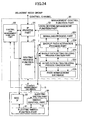
- Fig.24 shows another configuration example of the path switching apparatus of the present invention.
- the path switching apparatus of this embodiment includes an electrical switch part 30 instead of the optical switch part 10 of the embodiment 1-6.
- the electrical switch part 30 includes an electrical switch function part 31, a switch control part 32 for controlling the electrical switch function part 31, and a digital cross-connect interface (DCC-IF) 33 for exchanging a control signal with the management control function part 20, and realizes digital cross-connection SONET OC-48 links by 32 ⁇ 32.
- DCC-IF digital cross-connect interface
- the control link is formed by using the DCC channel of the SONET OC-48.
- the control signals are, for example, a OSPF/IS-IS protocol packet for obtaining a network topology, a RSVP-TE/CR-LDR protocol packet for setting/releasing a path set between packet switches, and a LMP protocol packet for performing failure monitoring of each fiber link.
- a configuration of the management control function part 20 is also the same. In this embodiment, it manages and controls VC-4 (155 M bit/s) channels defined in SONET instead of an optical channel.
- automatization of backup path setting can be performed.
- reliable failure recovery for a single link failure can be realized while minimizing the amount of facilities for backup paths, and occurrence rates of an idle state against multiple link failures can be differentiated according to service grades provided to users.
- Fig.25 shows a configuration example of a path switching apparatus of the embodiment 3-1.
- This apparatus forms an ATM switch for realizing switching of virtual paths (VP) defined on an ATM network.
- VP virtual paths
- the path switching apparatus includes an ATM switch part 10, a management control function part 20 for managing and controlling it, and an ATM link channel management database 15.
- the ATM switch part 10 includes an switch function part 11 and a switch control part 12 for controlling the switch function part 11.
- This configuration is almost the same as the path switching apparatuses of the embodiments 1-5 and 2-1, but a point is that, instead of an optical path, VP is dealt with differently. Also, functions of each part are the same as those of the embodiment 2-1 except for the point that, instead of an optical path, VP is dealt with.
- the management control function part 20 includes function parts for processing control signal protocols, and includes a routing process function part (OSPF/IS-IS protocol process function) 21 for realizing setting / releasing /switching / routing of VPs, a path setting management function part (RSVP-TE/CR-LDR protocol process function) 22 for performing VP setting / releasing signaling, a control link management function part (LMP protocol process function) 23 for performing failure monitoring of a control link network in which control signals are transmitted, and an IP process part 24.
- OSPF/IS-IS protocol process function OSPF/IS-IS protocol process function
- RSVP-TE/CR-LDR protocol process function path setting management function part
- LMP protocol process function control link management function part
- the routing process function part 21 has functions for defining a cost for each ATM link, and searching for a route for which an ATM link cost accumulated between a source node and a destination node of a VP to be established is minimum. Dijkstra's algorithm can be applied for the search algorithm.
- the path setting management function part 22 includes a signaling process part 221 that is a core of the RSVP-TE protocol, an active path setting/deleting process part 222, a backup path setting/deleting process part 223, a backup path activation process part 224 and a path management database 225.
- the signaling process part 221 may be similarly configured by using a core of a CR-LDP protocol.
- the active path setting/deleting process part 222, the backup path setting/deleting process part 223 and the backup path activation process part 224 are connected to the ATM link channel management database 15.
- the active path setting/deleting process part 222 and the backup path setting/deleting process part 223 are connected to the routing process function part 21.
- the active path setting/deleting process part 222 and the backup path activation process part 224 are connected to the switch control part 12.
- signaling information is input to and output from the active path setting/deleting process part 222.
- signaling information is input and output to and from the backup path setting/deleting process part 223.
- a database for managing ATM link channels according to a management model of Fig.26 is constructed.
- the ATM network as shown in Fig.26, three layers of a VC layer, a VP layer and an ATM link layer are separated and managed.
- the ATM link channel management database 15 includes a risk classification database holding risk classification number information of the path switching apparatus and each link connected to the path switching apparatus, and risk classification number information registered for ATM links that are accommodated in the path switching apparatus.
- VPI VP identifier
- VPIs of bandwidths M used for recovery of a backup path and channels are bundled for the sake of management, and are managed as a channel group (a VPI group).
- a VPI group of each link is designated.
- the backup path setting/deleting process part 223 collectively manages M (M ⁇ L) backup path bandwidths as a VPI group in L backup path bandwidths kept as bandwidths for accommodating backup paths connected to the same nodes.
- an identification number is assigned for identifying each VPI group, and the backup path setting/deleting process part 223 selects channels that become members of the VPI group, and outputs the identification information of the channels to a database by linking the identification information with corresponding VPIs.
- the signaling process part 221 outputs a backup path activation signal communicated from an adjacent node to the backup path activation process part 224, and outputs a backup path activation signal sent from the backup path activation process part 224 to an adjacent node.
- the signaling process part 221 distributes the information to the backup path setting/deleting process part 223.
- the backup path setting/deleting process part 223 searches for an output port of the backup path by referring to a routing table of the routing process function part 21, and outputs identification number information of VPIs or a VPI group to be kept in an output side of the backup path to the signaling process part 221 so as to notify an adjacent node of the identification number information.
- the backup path activation process part 224 inputs/outputs a backup path activation signal with an adjacent node via the signaling process part 221. In addition, the backup path activation process part 224 performs actual backup path activation processes to drive the switch.
- backup path setting can be performed only by designating, for each link, a VPI group that accommodates backup paths.
- the apparatus can be controlled such that an active path is not set as a VPI forming the VPI group accommodating backup paths. Accordingly, each node can set a VPI to be "backup reserved" as a backup resource in an autonomous and distributed manner for each link.
- Fig.27 shows a configuration example of a communication network to which the present embodiment is applied.
- Bandwidth is kept in nodes #1 - #3 - #6 - #8 as an active path, then, the path is opened along the route.
- a bandwidth is only reserved in nodes #1 - #2 - #4 - #7 - #8 as a backup path, and actual connection setting is not performed until the active path is disconnected due to a certain failure for the active path.
- risk classification number information that is assigned to the active path corresponding to the accommodated backup path is recorded.
- ⁇ 12, 18, 21 ⁇ is assigned as risk classification number information that is a failure scenario of a route of the active path.
- risk classification number information ⁇ 12, 18, 21 ⁇ is attached as attribute information of the VPI group that accommodates the backup path for the active path.
- the risk classification number information is communicated one by one from a source-side node to a destination-side node when setting the backup path.
- Each node registers the risk classification number information in the ATM link management database 15 via its own signaling process part 221.
- the risk classification number information is associated with identification number information of the VPI group that accommodates the backup path, and is stored in each ATM link management database 15 in every node on the backup path route.
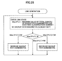
- Fig.28 shows a backup path setting process sequence in the backup path setting/deleting process part 223 according to the embodiment 3-1.
- a total sum of backup path bandwidths registered in a VPI group is b
- a total sum of backup paths to be switched to the VPI group when a switching operation from active paths to backup paths occur is P(r) for a switching factor of a risk classification number r
- a maximum value of the sum of backup paths P(r) obtained for the risk classification number r is Max ⁇ P(r) ⁇
- the backup path setting/deleting process part 223 sends, to the signaling process part 221, a command for setting bandwidths M of backup paths forming the VPI group to be equal to or greater than Max ⁇ P(r) ⁇ and equal to or less than b.
- the backup path bandwidths M forming the VPI group becomes smaller than Max ⁇ P(r) ⁇ , the backup path bandwidths are increased, if the backup path bandwidths M forming the VPI group becomes larger than Max ⁇ P(r) ⁇ , the backup path bandwidths are decreased; if they are the same, no process is performed.
- setting of the backup path is performed in consideration of the risk classification number information assigned to the active path.
- necessary backup path bandwidths can be kept while checking backup path bandwidths that form the VPI group whenever necessary.
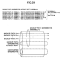
- M 800 Mbit/s
- the backup path bandwidth forming the VPI group is increased to 1000 M bit/s. Accordingly, 100 % recovery can be realized for a single failure for the four paths that pass through a link of the risk classification number ⁇ 12 ⁇ .
- the backup path is set in consideration of risk classification number information added to the active path, so that backup path resources can be reduced as much as possible while realizing 100% recovery for a single failure.
- backup path bandwidth necessary for a VPI group backup path bandwidth that belongs to the VPI group can be dynamically added/deleted.
- attribute information of failure service classes is added to the VPI group that accommodates backup paths.
- path non-available rates due to multiple failures are differentiated so as to delicately serve failure service grade needs for users.
- Fig.31 shows a backup path setting process sequence of the backup path setting/deleting process part 223 in the embodiment 3-2.
- limitations are applied in processes such that only a backup optical path for an active path of a failure service class the same as (or smaller than) a failure service class held by the VPI group is accommodated in the VPI group.
- a positive value a (f) according to failure service class attribute information f is defined.
- ⁇ is a backup path bandwidth necessary for a VPI group of the failure service class attribute f
- min ⁇ a(f) ⁇ Max ⁇ P(r) ⁇ , b ⁇ is used as ⁇ .
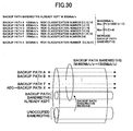
- the backup path bandwidth of 800Mbit/s is not enough for restoring the active paths of the risk classification number ⁇ 2 ⁇ with the failure service class "Gold".
- the backup path bandwidth forming the VPI group is increased to 1000 Mbit/s. Accordingly, shared restoration for the failure service class "Gold" can be realized. That is, even if failures occur for a larger number of active paths, the probability of recovery becomes high for active paths to which a high failure service class is set, so that the path non-available rate due to multiple failures can be decreased.
- VP of ATM is taken as an example in the above-mentioned descriptions in the embodiments, the present invention can be also applied to failure recovery for a Label Switched Path of a Multi Protocol Label Switch router defined by a similar concept.
- automatization of backup path setting can be performed.
- reliable failure recovery for a single link failure can be realized while minimizing an amount of facilities for backup paths, and occurrence rates of an idle state against multiple link failures can be differentiated according to service grades provided to users.
- M backup optical channels are defined for each link section, and N active optical paths share the backup optical channel resources as own backup resources.
- a database that manages resources of M backup optical channels is in a state in which only identification number information of active optical paths that use the M backup optical channel resources as backup optical path resources is registered. That is, until an active path is switched to a backup optical path after a failure occurs, an optical channel that accommodates the backup optical path is not determined.
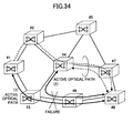
- Fig.36 shows a configuration example of an optical communication network to which the high-speed path switching method of the present embodiment is applied.
- An active optical path (1) keeps a bandwidth in nodes #1 - #3 - #6 - #8, an active optical path (2) keeps a bandwidth in nodes #4 - #3 - #6 - #8, an active optical path (3) keeps a bandwidth in nodes #4 - #5, and an active optical path (4) keeps a bandwidth in nodes #5 - #7.
- link disconnection occurs between nodes #3 - #6
- switching operation occurs in active optical paths (1) and (2) that pass through the link section.
- a switching signaling for the active optical path (1) occurs in nodes #1 - #2 - #4 - #7 - #8, and that a switching signaling for the active optical path (2) occurs in nodes #8 - #7 - #4.
- optical channels of 32 waves are defined in which an optical channel group kept for backup optical path setting has 2 waves.
- backup optical paths are registered for four active optical paths (1) - (4) in total. That is, the optical channel group supports a 2:4 shared restoration method.
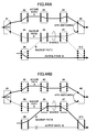
- Fig.37 shows a signaling sequence in the high-speed path switching method of the present embodiment.
- the node #4 and the node #7 that are adjacent to each other share roles of a master node and a slave node as a result of communications using the OSPF or LMP protocol.
- a node having a larger node identification number between the two nodes is determined to be the master node and a node having a smaller node identification number is determined to be a slave node.
- the reverse order may apply.
- the RSVP-TE protocol is used for a signaling sequence.
- Fig.39 is a block diagram of the path switching apparatus of this embodiment. This configuration is the same as that of the path switching apparatus described in the embodiment 1-5. This embodiment is different from the embodiment 1-5 in that the backup optical path activation process part 224 and the like activate backup optical paths using the method described in the embodiment 4-1.
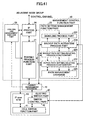
- Fig.40 is a block diagram of the path switching apparatus of the present embodiment.
- the path switching apparatus of this embodiment includes an electrical switch part 30 instead of the optical switch part 10 of the embodiment 4-2.
- the electrical switch part 30 includes an electrical switch function part 31, a switch control part 32 for controlling the electrical switch function part 31, and a digital cross-connect interface (DCC-IF) 33 for exchanging a control signal with the management control function part 20, and realizes a digital cross-connection for 32 ⁇ 32 SONET OC-48 links.
- DCC-IF digital cross-connect interface
- the control link is formed by using the DCC channel of the SONET OC-48.
- the control signals are, for example, an OSPF/IS-IS protocol packet for obtaining a network topology, a RSVP-TE/CR-LDR protocol packet for setting/releasing a path set between packet switches, and a LMP protocol packet for performing failure monitoring of each fiber link.
- the configuration of the management control function part 20 is the same as that of the embodiment 4-2.
- the VC-4 155 Mbit/s defined in SONET instead of the optical channel is managed and controlled.
- Fig.41 is a block diagram of a path switching apparatus in this embodiment.
- the path switching apparatus of this embodiment includes an electrical switch part 40 instead of the optical switch part 10 of the embodiment 4-2.
- the electrical switch part 40 includes a cell switch function part 41, a switch control part 42 for controlling the cell switch function part 41, and a control signal interface (IP over ATM) 43 for exchanging a control signal with the management control function part 20, and can accommodate 32 input/output SONET OC-48 links, and realizes cell switching among them.
- IP over ATM control signal interface
- the control link is formed by using a common signaling network of a communication carrier.
- the control signals are, for example, an OSPF/IS-IS protocol packet for obtaining a network topology, a RSVP-TE/CR-LDR protocol packet for setting/releasing a path set between packet switches, and a LMP protocol packet for performing failure monitoring of each fiber link.
- the configuration of the management control function part 20 is the same as that of the embodiment 4-2.
- the management control function part 20 manages and controls VPIs defined between ATM switches.
- the VPI defined for each link between nodes corresponds to a channel that accommodates an optical path or an electrical path. That is, as shown in the figure, to correlates VPIs between input and output in each node apparatus corresponds to cross-connection operation for optical paths or electrical paths.
- This embodiment can be applied to a label switch router that can provide a virtual path for IP packet traffic by using layer 2.5 MPLS technology, and in the same way, applied to an Ether over MPLS switch that can provide a virtual path for an Ether frame.
- routes for the active path and the backup path are selected such that the routes are different from each other except for a source node and a destination node. Further, bandwidth reservation is performed beforehand for the route of the backup path before a failure of the active path occurs, and the backup path bandwidth is shared with a backup path defined to recover other active paths.
- nodes #1 - #2, nodes #2 - #3, nodes #1 - #4, nodes #2 - #5, nodes #3 - #6, nodes #4 - #5 and nodes #5 - #6, respectively are connected by links of risk classification numbers ⁇ 11 ⁇ , ⁇ 12 ⁇ , ⁇ 13 ⁇ , ⁇ 14 ⁇ , ⁇ 15 ⁇ , ⁇ 16 ⁇ and ⁇ 17 ⁇ .
- a backup optical path A for the active optical path A is set on a route passing through links of risk classification numbers ⁇ 13, 16, 17 ⁇
- a backup optical path B of active optical path B is set in a route passing through links of risk classification numbers ⁇ 14, 17, 15 ⁇
- a backup optical path C of the active optical path C is set in a route passing through links of risk classification numbers ⁇ 12, 15, 17 ⁇ .
- a backup optical channel is shared such that a single failure of any one of links of risk classification numbers ⁇ 11 ⁇ , ⁇ 12 ⁇ , ⁇ 14 ⁇ and ⁇ 15 ⁇ that the active optical path passes through does not hinder recovery.
- the restoration method since a maximum number of active optical paths that pass through the link of the risk classification number ⁇ 12 ⁇ is 2, it is adequate if the paths can be switched to backup optical paths when the failure of the link occurs, so that two is adequate for the number of the backup optical channels.
- the restoration method enables a network facility amount for accommodating backup paths to be largely decreased by making the most of it.
- a first method is a method for flooding the whole network with the failure notification from a node of a failure detected point.
- the failure notification can be sent to each node on a backup path from the node of the failure detected point in the shortest route, so that realization of a quick failure switching operation can be expected.
- this method assumes that the failure notification is sent to the whole network when the failure occurs, so that the failure notification needs to be transferred to nodes for which actual failure switching operation is unnecessary. For this reason and the like, the method includes an inefficient aspect.
- a second method is a method for notifying a switching point node of the active path - backup path of a failure occurrence from a node of the failure detected point (the nodes are the same in the figure), and multicasting the failure notification from the switching point node to each node on the backup path.
- this method it is also assumed that each channel of each link to which the backup path is to be assigned is determined beforehand.
- a third method is a method for notifying a switching point node of the active path - backup path of a failure occurrence from a node of the failure detected point (the nodes are the same in the figure), and transferring the failure notification from the switching point node to each node on the backup path in an order of the route.
- the failure recovery operation is prone to become slow compared with the first method since the failure occurrence needs to be sent from the failure detected point to the switching point node.
- failure detection of a SDH path or an optical path it is not necessarily limited to a node adjacent to the failure occurrence point, so that the detection can be performed at the switching point to the backup path.
- AIS alarm indication signal
- a failure can be detected by the same function or power interruption of an optical path signal itself. Therefore, as to failure recovery for the SDH path and the optical path, switching to the backup path can be performed at a relatively high speed even by the third method.
- the channels to which the backup path is assigned in each link since the channels can be determined in an order from a source-side node to a destination-side node (or the reverse direction) while transferring the failure notification, a flexible operation can be realized.
- the time is a cumulative sum of (1) a transmission delay of the failure notification in the backup path that is determined by transmission speed of an optical signal, and (2) a transferring delay of the failure notification in each node.
- the former delay is accumulated in a ratio of 5 milliseconds per 1000 km, and the latter delay is accumulated about 1-10 milliseconds per 1 node. Therefore, for example, in the restoration method that requires failure recovery within 50 milliseconds, it becomes difficult in effect to make settings such that a route of a backup path includes no less than several nodes, which causes the network scale to be limited. From a viewpoint of this, embodiments on technology to perform switching quickly are described in the following.
- Figs.44A and B are figures for describing the high-speed path switching method of this embodiment.
- an active path A is set between nodes #1 - #2 - #3 - #4 - #8
- a backup path A is set between nodes #1 - #5 - #6 - #7 - #8
- an active path B is set between nodes #9 - #10
- a backup path B is set between nodes #9 - #6 - #7 - #10.
- the backup path A for which a large delay (for example, equal to or greater than 20 milliseconds) is expected in the switching process in transferring the failure notification
- a large delay for example, equal to or greater than 20 milliseconds
- Such a backup path is called "hot state backup path”.
- physical connections are not performed in each node on the route of the backup path B, so that backup path bandwidth is only reserved (shown as dotted lines in the figure).
- the hot state backup path is set when a route length exceeds a predetermined length or when a number of passing nodes exceeds a predetermined number.
- a source node #1 of the backup path A the same data (only a payload part of a SDH frame in the SDH transmission system) as one in the active path A is copied, and the data are transferred to a destination node #8.
- the active path A is switched to the backup path A by APS (Automatic Protection Switching) in the destination node #8.
- the switching from the active path A to the backup path A can be performed quickly and independent of the backup path route length by only performing a switching process in the destination node when a failure occurs in the active path A. This applies to a reverse direction path in which the node #8 is a source and the node #1 is a destination.
- a backup path bandwidth is only reserved, and physical connections are not performed in each node on the route until a failure switching occurs. Therefore, the backup path A and the backup path B share bandwidth between nodes #6 - #7, and are treated equally.
- the present embodiment allows bandwidth allocated to the hot state backup path to be released as means for restoring another active path. That is, when the backup path B is set between nodes #6 - #7, a sharing effect of a backup band can be obtained in the same way as the conventional pre-assign restoration method in that the bandwidth between the nodes #6 - #7 is shared by the backup path A and the backup path B.
- a concrete example is described below.
- the conventional 1+1 protection method since the same data are transmitted in the active path and in the backup path, the conventional 1+1 protection method is the same as the hot state backup path of this embodiment in that failure switching for the active path can be supported by APS switching at an end node. But, the conventional 1+1 protection method is different from the present invention in that, since both the active path and the backup path are used as "active" in effect, bandwidth that is allocated to the backup path cannot be shared with other backup paths.
- copied data of the active path are not transmitted over the backup path, and bandwidth allocated to the backup path is shared by plural backup paths for restoring plural active paths.
- These active paths are assumed to be established between the same start and end nodes. Thus, it is not assumed to share bandwidth between arbitrary sections of the backup path as in the present embodiment.
- Figs. 44A and 44B an operation example of the path switching method of the present invention is provided with reference to Figs. 44A and 44B.
- the backup path A having long route length is set as the hot state backup path that is physically connected.
- the backup path B a bandwidth is only reserved and the path is not physically connected.
- the backup paths A and B share the same optical channel, but only the backup path A is actually connected between the nodes #6 and #7.
- a failure occurs in the active path A in this state, as shown in Fig.44A, switching from the active path A to the backup path A is performed by APS switching. At this time, switching from the active path A to the backup path A ends, so that the backup path A can be used as an active path. At this time, information indicating that the backup path A has been switched to an active path is sent from the start node #1 of the active path A to each node on the route of the backup path A in an order of the nodes on the route.
- This method is the same as the conventional failure notification method shown in Fig.43C. But, since failure switching has already been ended, transfer delay of failure notification does not cause any problem.
- this notification as to the backup path B, use of the bandwidth that the backup path B shares with the backup path A between the nodes #6 and #7 is prevented, and a state in which the active path that is switched from the backup path A is physically connected is kept.
- the failure recovery process is performed by the failure notification, and on the other hand, for a backup path having a long route length, APS switching is realized and backup path bandwidth (optical channel) is shared with the backup path having a short route length. Accordingly, failure recovery can be completed within a predetermined time for all optical paths against any failure occurrence. At the same time, backup path bandwidth sharing effects the same as the effects of the restoration method that does not use the hot state backup path can be expected, so that compatibility between economy and speed of failure recovery can be achieved.
- Fig.46 is a block diagram of the path switching apparatus of the present embodiment.
- the path switching apparatus includes an optical switch part 10 for realizing cross - connection for each optical path, a management control function part 20 for managing it and a channel management database 15.
- the optical switch part 10 includes an optical switch function part 11, a switch control part 12 for controlling the optical switch function part 11, and a control signal interface (IP over OCS) 13 for exchanging a control signal with the management control function part 20.
- IP over OCS control signal interface
- the configuration and the operation of the management control function part 20 are almost the same as those of the embodiment 1-5 excluding the path management part 225.
- the path management part 225 manages backup paths by distinguishing hot state backup paths from backup paths that are not the hot state backup paths.
- the path management part 225 includes means for allowing release of bandwidth occupied by the hot state backup paths as means for restoring other active paths.
- path trunk identification number information and input and output interface numbers are included as attribute information of the hot state backup path, the means indicate that the path is physically connected in each node excluding the start and end nodes, and bandwidth sharing with other backup paths is allowed.
- the path setting management function part 22 includes means for sending and receiving identification information indicating whether a backup path that is set between own node and an adjacent node is a hot state backup path. Accordingly, high speed failure recovery with the above-mentioned method can be performed autonomously and in a distributed manner in the whole network.
- the path setting management function part 22 when the path setting management function part 22 sends or receives, along a route of a backup path, a switching message for switching an active path to a backup path when a failure occurs, the path setting management function part 22 includes means for accessing the path management part 225 to obtain channel bandwidth information accommodating the hot state backup path, and select a switching destination of the backup path to generate a switching message including the channel bandwidth. Accordingly, in the case shown in Fig.44B, the setting of the hot state backup path that is physically connected can be released temporarily, and another backup path to be activated by a failure recovery process can be newly set. This enables the hot state backup path to switch rapidly, and enables bandwidth sharing the same as that of the restoration method that does not use the hot state backup path. In this method, it is assumed that bandwidth sharing between hot state backup paths is not performed.
- the path setting management function part 22 transfers a message, along path switching apparatuses on a route of a hot state backup path that restores the active path, for requesting not to release bandwidth of the hot state backup path for failure recovery for other paths when a failure occurs in the active path. Accordingly, when the hot state backup path is used as an active path, the bandwidth of the hot state backup path can be prevented from being used by other backup paths.
- the path switching method and the path switching apparatus of the present embodiments 5-1 and 5-2 by sharing the backup path bandwidth for plural backup paths (hot state backup path and normal backup path), amount of equipment required for the whole network can be decreased. Further, as to the backup path having a long route length, switching from an active path to the backup path can be performed rapidly, which is difficult by the normal restoration method.
- the bandwidth sharing of the backup paths is performed for achieving 100 % failure recovery for a single link failure.
- contention for bandwidth may occur in a section in which bandwidth sharing of backup paths is performed so that there may be a case where the failure recovery fails.
- a method is proposed in which priority order of failure recovery is provided to every path to be failure-recovered, so that coordination is available even when the conflict occurs during switching to a backup system that shares bandwidth.
- backup paths are switched to the backup system in a descending order of priority when the failure occurs. Accordingly, failure recovery is efficiently performed when multiple failures occur.
- contention control performed when multiple failures occur in the restoration method attaches importance to coordination when contention occurs. For example, a backup path having a higher priority is restored by priority. But, the contention control in the restoration method is not based on a viewpoint of recovering multiple failures as much as possible. In addition, both are controlled by a network management system that performs path management in a concentrated manner, so that there is a problem in speed of the failure recovery process, which leads to limiting the network scale.
- Fig.48 is a block diagram of a path switching apparatus including the path management apparatus of the present embodiment.
- the path switching apparatus includes an optical switch part 10 for realizing cross-connection for each optical path, a management control function part 20 for managing and controlling it and a channel management database 15.
- the optical switch part 10 includes a 64 ⁇ 64 optical switch function part 11, a switch control part 12 for controlling the optical switch function part 11, and a control signal interface (IP over OCS) 13 for exchanging a control signal with the management control function part 20.
- IP over OCS control signal interface
- a switch function part that inputs and outputs 8 SDH links of 2.5 Cbit/s and that can perform cross-connection processes for each VC-4 (150 Mbit/s) can be used.
- the configuration and the operation of the management control function part 20 are almost the same as those of the embodiment 1-5 excluding the path management apparatus 225.
- the path management apparatus 225 of the present embodiment has a function for sending, via the backup path activation process part 224 and the signaling process part 221, a setting state of a backup path to each node which the backup path passes through.
- the path management part 225 detects a backup path that cannot be activated (failure recovery unavailable) due to the fact that an optical channel that accommodates the backup path fails or the optical channel is used by another backup path, the path management part 225 notifies nodes through which the backup path passes with a "backup path activation impossible message".
- the path management apparatus 225 may ascertain the activation possibility for each section of two nodes through which the backup path passes so as to include the information in the "backup path activation impossible message".
- Figs.49A, B and C show methods for transferring the backup path activation impossible message.
- the "backup path activation impossible message" is multicasted from a node that detects the activation impossibility of the backup path to nodes through which the backup path passes.
- the "backup path activation impossible message" is sent from a node that detects the activation impossibility of the backup path to a start node of the backup path, and the "backup path activation impossible message” is multicasted from the start node to each node to an end node of the backup path.
- a backup path management message (Hello message of a standard specification in RSVP-TE protocol in the figure) is used in which the message is transferred periodically from a start node of the backup path to the end node (or reverse of this direction) for normality checking.
- a node that detects the activation impossibility of the backup path adds the "backup path activation impossible message" to the Hello message so that the message can be communicated to every node through which the backup path passes.
- the path management apparatus in a node that receives the "backup path activation impossible message" transferred in the above-mentioned way can ascertain, as management attribute information of the backup path, whether the backup path can be activated, so that performing useless switching processes for a backup path that cannot be activated can be avoided. Accordingly, useless contention in which plural backup paths including the backup path that cannot be activated try to keep bandwidth can be avoided.
- each node through which the backup path passes can know that the backup path cannot be activated when a channel that accommodates the backup path fails or is already used for another backup path in another node section, for example.
- a channel of the backup path can be used for another backup path so that there is a high probability that the other backup path can be restored even when multiple failures occur as described in the following.
- Fig.50 shows a path management example in the path management apparatus of the present embodiment.
- an optical channel 1 is assigned solely to a backup path A of a failure service class 1
- an optical channel 2 is shared by backup paths B, C and D of a failure service class 2.
- the backup path A cannot keep an optical path in another node section due to the fact that a failure occurs or the optical channel is used by another backup path
- the backup path A cannot be activated, so that the optical channel 1 that accommodates the backup path A in the node is not used.
- the backup path A cannot be activated, so that the optical channel 1 that accommodates the backup path A in the node is not used.
- the backup path A cannot be activated, so that the optical channel 1 that accommodates the backup path A in the node is not used.
- multiple failures occur in a section corresponding to the backup paths B and C so that it becomes necessary to keep an optical channel at the same time so that contention for a shared optical channel 2 occurs.
- the optical channel 1 that accommodates the backup path A can be diverted for an optical channel for accommodating the backup path B or the backup path C. Accordingly, simultaneous recover by the backup paths B and C can be performed for multiple failures.
- Fig.51 shows another path management example in the path management apparatus of the present embodiment.
- backup paths A and B of the failure service class 1 share the optical channel 1
- the backup paths C, D and E of the failure service class 2 share the optical channels 2 and 3.
- the backup paths A and B try to keep the optical channel 1 simultaneously due to occurrence of multiple failures.
- the optical channel 2 or the optical channel 3 that accommodates the backup paths C, D and E of a lower failure service class is diverted for an optical channel for accommodating the backup path A or the backup path B. Accordingly, simultaneous recovery by the backup paths A and B can be performed for multiple failures.
- the path management apparatus of the present embodiment for a backup path that cannot keep a channel that accommodates the backup path at another node section, activation of the backup path is made impossible, and the impossibility of activation of the backup path is communicated to nodes through which the backup path passes, so that useless contention between plural backup paths including the backup path that cannot be activated when multiple failures occur is avoided.
- the notification of the activation impossible backup path by performing path management in which the channel for the activation impossible backup path is diverted or a channel for a backup path of a lower failure service class is diverted, it becomes possible to increase activation success probability when multiple failures occur.
- a network using optical routers is configured such that a data plane formed by switch function parts for transferring user information and a control plane formed by control apparatuses for transferring control signals of the communication network are separated.
- the data plane is a highly reliable network based on the SDH or OTN (Optical Transport Network) technique.
- the control plane is a network based on Ether switches or IP routers. Generally, the network configuration of the control plane has higher redundancy than the data plane.
- LMP Link Management Protocol
- a control channel is established between adjacent nodes in the data plane via control apparatuses in the control plane, and a hello packet for communicating only a sequence number is exchanged between the nodes via the control channel.
- the exchange period of the hello packet is 10 ⁇ 100 msec in the standard, so that abnormality detection can be performed rapidly.
- LMP Degraded State in which the control plane is abnormal, it is necessary in each node to prevent the failure of the control plane from adversely affecting the normal data plane. For example, it is necessary to eliminate unnecessary switching operations due to misidentifying disconnection of a path set in the data plane or control channel failure as link disconnection.
- the path of the data plane is set by signaling processes via the control plane shown in Fig.52.
- a path setting state is semipermanently stored in each node unless there is a clear disconnection instruction, and a cross-connection state for opening a path is kept.
- the advantage of the hard state is that maintaining and managing processes for the path state that is once set are unnecessary. Even when a failure occurs in the control plane, disconnection and unnecessary switching operations do not occur. On the other hand, when a large scale disaster that may cause an outage of a node occurs, it becomes difficult to quickly reestablish a network using the remaining normal network apparatuses.
- a failure path disconnection instruction is not provided to the paths of nodes #1-#2 and nodes #3-#6, so that inoperative paths remain and a state in which network resources are uselessly consumed continues.
- normality check for a path that is set is performed by periodic signaling processes via the control plane.
- the hello packet for checking normality of a path is periodically exchanged between path ends.
- a path setting state in each node is deleted, and a cross-connection state for opening the path is released. Accordingly, occurrence of inoperative paths is reduced so that a waste of network resources due to a path registration deleting error can be completely eliminated.
- a soft-hard state is defined as a middle state.
- the soft-hard state is a soft state in which the path setting is not as semipermanent as the hard state but the path setting is not deleted in a failure of several days.
- the soft-hard state is applied to so called legacy services such as the telephone, the digital private line, and the ATM private line.
- the conventional soft state is provided to a line that accommodates public IP traffic of a low quality class.
- a network control apparatus that provides a control function necessary for realizing such path management and that enables control for suppressing disconnection of a normal path set on the data plane and suppressing an unnecessary switching operation as adverse effects due to failure of the control plane.
- a soft state is introduced for deleting path management information registered in the path management database when a normal check elapsed time exceeds a threshold. State transition from the soft state to the hard state is triggered by detecting a state (LMP Degraded State) of an abnormality in the control plane in a node.
- LMP Degraded State a state of an abnormality in the control plane in a node.
- a node that detects the LMP Degrade checks normality of the data link corresponding to the control link. If there is no abnormality in the data link, a path that passes through the data link is changed to the soft-hard state. Further, the event of the state transition is communicated to all nodes through which the path passes for transferring the path from the soft state to the soft-hard state. Accordingly, disconnection of a normal path set on the data plane and an unnecessary switching operation due to failure of the control plane can be suppressed.
- Transition from the soft-hard state to the soft state is performed when recovery of the control link is verified and normality of the data link is verified. Also in this case, in the same way, the transition is communicated to all nodes through which the path passes such that all nodes recognize the transition.
- Fig.54 shows the above-mentioned state transition.
- Fig.55 shows a network control apparatus of the embodiment 7-1.
- the network control apparatus includes an optical switch part 10 for realizing cross-connection for each wavelength path, a management control function part 20 for managing and controlling it, and a channel management database 15.
- the optical switch part 10 includes an optical switch function part 11 and a switch control part 12 for controlling the optical switch function part 11.
- the optical switch part 10 of this embodiment uses a 128 ⁇ 128 switch and has a function for inputting and outputting four fiber links each multiplexing 32 waves of optical paths.
- the transmission speed of each optical path is 2.5 Gbit/s, and is terminated with a SONET OC-48 interface.
- Control links are formed by SONET OC-3 lines each having a transmission speed of 155 Mbit/s.
- the control signals are an OSPF/IS-IS protocol packet for obtaining a network topology of the optical network, a RSVP-TE/CR-LDR protocol packet for setting and releasing an optical path between packet switches, and a LMP protocol packet for performing failure monitoring for each fiber link.
- the management control function part 20 includes a function part for processing the control signal protocols, and includes a routing process function part (OSPF/IS-IS protocol process function) 21 for realizing setting / releasing /switching / routing of an optical path, a path setting management function part (RSVP-TE/CR-LDR protocol process function) 22 for performing setting / releasing signaling for an optical path, a control link management function part (LMP protocol process function) 23 for performing failure monitoring of a control link network in which control signals are transmitted, and an IP process part 24.
- OSPF/IS-IS protocol process function OSPF/IS-IS protocol process function
- RSVP-TE/CR-LDR protocol process function path setting management function part
- LMP protocol process function control link management function part
- the path setting management function part 22 includes a signaling process part 221, an active path setting/deleting process part 222, a backup path setting/deleting process part 223, a backup path activation process part 224 and a path management database 225 for performing setting management for paths that are set on the data network, and a timer process part 226.
- the signaling process part 221 not only performs establishment and deletion of a path, and a switching notification process associated with path failure recovery, but also keeps path setting by exchanging the hello packet periodically between path ends after path setting.
- the signaling process part 221 notifies the timer process part 226 of arrival of the hello packet and a path identification number of a path on which the hello process has been performed, and the timer process part 226 resets the timer process for the path.
- the path setting is kept by periodically exchanging the hello packet for each of an active path and a backup path, and the timer process part 226 generates a process or an instance for the timer process for each path.
- the path management information registered in the path management database 225 is deleted, and the channel management database 15 for managing wavelength channels between optical cross-connects is operated so that a state of a channel occupied by the path to be deleted is changed to an unoccupied state. Further, the cross-connection state of the optical switch part 10 is released.
- the control link management function part 23 detects abnormality of a control link connected to its own node, and verifies normality of a data link corresponding to the control link
- the control link management function part 23 outputs a timer stepping signal to the timer process part 226 that is performing the timer process for the path in which setting maintenance (exchange of hello packet) is performed via the control channel in which the failure has occurred.
- the path for which the timer stopping process is performed is limited to one for which the exchange of the hello packet is performed via the control channel in which the failure occurred.
- the search for the corresponding path is performed by making an inquiry to the active path setting/deleting process part 222 and to the backup path setting/deleting process part 223 from the signaling process part 221.
- the timer process part 226 receives the timer stopping signal so as to stop the timer process of the normality check elapsed time of the set path. Accordingly, an accidental disconnection process of paths associated with the failure of the control link can be avoided. That is, these paths are changed from the soft state to the soft-hard state.
- the signaling process part 221 performs the timer stopping process for a path for which the exchange of the hello packet is performed via the control link.
- the path in which the state is changed from the soft state to the soft-hard state all nodes through which the path passes are notified of the transition. Accordingly, all sections of the path are changed from the soft state to the soft-hard state.
- a signaling protocol such as RSVP-TE or CR-LDP is used.
- Fig.58 shows a block diagram of the network control apparatus of the embodiment 7-2.
- the network control apparatus of this embodiment includes an electrical switch part 30 instead of the optical switch part 10 of the embodiment 7-1.
- the electrical switch part 30 includes a digital cross-connect switch function part 31 of 32 ⁇ 32 for realizing cross-connection for each SDH frame VC-4 (155Mbit/s), a switch control part 32 for controlling it, and a digital cross connect interface (DCC-IF) 33 for exchanging a control signal with the management control function part 20.
- DCC-IF digital cross connect interface
- the control circuit is configured by using a DCC channel of the STM 16 signal.
- the control signals are, for example, an OSPF/IS-IS protocol packet for obtaining a network topology, a RSVP-TE/CR-LDR protocol packet for setting or releasing a path established between packet switches, and a LMP protocol packet for performing failure monitoring of each fiber link.
- the configuration of the management control function part 20 is almost the same as that of the embodiment 7-1, but functions are added to the control link management function part 23, which functions are a function for notifying an adjacent node of abnormality of a control link connected to the own node, and a function for notifying an adjacent node of the abnormality of the control link that is communicated from another adjacent node. Accordingly, the failure of the control link is communicated to the whole control area, so that all paths set in the control area are changed from the soft state to the soft-hard state. At the same time, new establishment of a VC-4 path that passes through the control area is temporarily stopped, so as to realize stable path operation.
- the soft state is introduced to the communication network, and at the same time, disconnection operation and unnecessary switching operation for the VC-4 path associated with the introduction of the soft state are suppressed in a predetermined area, so that stable path operation can be kept.
- the present invention is applied to the digital cross-connect network for realizing a networking of the STS-3/VC-4 path of the SONET/SDH frame
- the present invention can be also applied to management control of virtual paths of the ATM network and label switched paths of the MPLS network.
Landscapes
- Engineering & Computer Science (AREA)
- Computer Networks & Wireless Communication (AREA)
- Signal Processing (AREA)
- Data Exchanges In Wide-Area Networks (AREA)
- Telephonic Communication Services (AREA)
Abstract
Description
wherein each node is connected to the same destination, and channel identification number information of M (M is a natural number equal to or less than L) channels in L (L is a natural number) channels kept as backup path bandwidth are held,
when assuming that n (n is a natural number) indicates a number of backup paths registered in a channel group in a link connecting two nodes, P(r) indicates a number of backup paths to be switched to any of the M channels when a switching operation from an active path to a backup path relating to a switching factor of a risk classification number r occurs, and that Max{P(r)} indicates a maximum value of P(r) for each risk classification number r, the number M of channels to be kept as the backup path bandwidth in the link is set such that M is equal to or greater than Max{P(r)} and equal to or less than n.
wherein each node is connected to the same destination, M (M is a natural number equal to or less than L) channels in L (L is a natural number) channels kept as a backup path bandwidth are defined as a channel group, and identification number information for identifying each channel group are held,
when assuming that n (n is a natural number) indicates a number of backup paths registered in a channel group in a link connecting two nodes, P(r) indicates a number of backup paths to be switched to the channel group when a switching operation from an active path to a backup path relating to a switching factor of a risk classification number r occurs, and that Max{P(r)} indicates a maximum value of the number P(r) for each risk classification number r, the number M of channels forming the channel group in the link is set such that M is equal to or greater than Max{P(r)} and equal to or less than n.
each backup path having the failure service class attribute information f is accommodated in the channel group having the same failure service class attribute information f, and
the number M of channels forming the channel group of the failure service class attribute information f in the link is set to be equal to or greater than a(f)×Max{P(r)} and equal to or less than n when a (f)×Max{P(r)} is equal to or less than n, and is set to be equal to or less than n when a (f)×Max{P(r)} is greater than n.
each backup path having the failure service class attribute information f is accommodated in the channel group having the same failure service class attribute information f,
wherein the path setting management part includes a function for setting the number M of channels forming the channel group of the failure service class attribute information f in the link to be equal to or greater than a(f)×Max{P(r)} and equal to or less than n when a(f)×Max{P(r)} is equal to or less than n, and setting the number M to be equal to or less than n when a(f)×Max{P(r)} is greater than n.
when assuming that b indicates a total sum of backup path bandwidths registered in a VPI group in a link connecting two nodes, P(r) indicates a total sum of backup path bandwidths to be switched to any of the VPI group when a switching operation from an active path to a backup path relating to a switching factor of a risk classification number r occurs, and that Max{P(r)} indicates a maximum value of the backup path bandwidths P(r) for each risk classification number r, the bandwidth M to be kept as the backup path bandwidth in the link is set such that M is equal to or greater than Max{P(r)} and equal to or less than b.
when assuming that b indicates a total sum of backup path bandwidths registered in the VPI group in a link connecting two nodes, P(r) indicates a total sum of backup path bandwidths to be switched to the VPI group when a switching operation from an active path to a backup path related to a switching factor of a risk classification number r occurs, and that Max{P(r)} indicates a maximum value of backup path bandwidths P(r) for each risk classification number r, the backup path bandwidth M forming the VPI group in the link is set such that M is equal to or greater than Max{P(r)} and equal to or less than b.
each backup path having the failure service class attribute information f is accommodated in the VPI group having the same failure service class attribute information f, and
the backup path bandwidth M of the VPI group of the failure service class attribute information f in the link is set to be equal to or greater than a(f)×Max{P(r)} and equal to or less than n when a(f)×Max{P(r)} is equal to or less than n, and is set to be equal to or less than n when a(f)×Max{P(r)} is greater than n.
each backup path having the failure service class attribute information f is accommodated in the VPI group having the same failure service class attribute information f, and the path setting management function part includes:
when the backup path accommodated in the channel group is activated, the master node activates channels in turn from a channel having a small (or large) identification number, and the slave node activates channels in turn to form a channel having a large (or small) identification number.
a function for sending abnormality of a control link information received from an adjacent node to another adjacent node.
The active path setting/deleting
| Node ID | Output IF |
| 10.10.105.1 | IF 1 |
| 10.10.105.2 | IF 2 |
| 10.11.106.2 | IF 1 |
Claims (46)
- A backup path bandwidth keeping method for keeping a bandwidth of a backup path to which an active path is switched when the active path becomes unavailable in nodes of a communication network, wherein each node is connected to the same destination, and the method includes, as to M (M is a natural number equal to or less than L) channels in L (L is a natural number) channels that are kept as a backup path bandwidth:a backup path bandwidth keeping phase, when keeping the bandwidth of the backup path, for sending identification number information of the M channels to be kept and identification information indicating that a path for which the bandwidth is to be kept is a backup path, to destination-side nodes existing in a destination side of the backup path.
- A backup path bandwidth keeping method for keeping a bandwidth of a backup path to which an active path is switched when the active path becomes unavailable in nodes of a communication network, wherein each node is connected to the same destination, M (M is a natural number equal to or less than L) channels in L (L is a natural number) channels kept as a backup path bandwidth are defined as a channel group, and identification number information for identifying the channel group is held, the method includes:a backup path bandwidth keeping phase, when keeping the bandwidth of the backup path, for sending identification number information of the channel group to be kept and identification information indicating that a path for which the bandwidth is to be kept is a backup path, to a destination-side node existing in a destination side of the backup path.
- A backup path bandwidth keeping method for keeping a bandwidth of a backup path to which an active path is switched when the active path becomes unavailable in nodes of a communication network, wherein each node is connected to the same destination, M (M is a natural number equal to or less than L) channels in L (L is a natural number) channels kept as a backup path bandwidth are defined as a channel group, the method includes:a phase for recommending identification number information of each channel that is a candidate of a member of the channel group and identification information indicating that the channel group is a backup resource, to a master node; anda backup channel group keeping phase in which the master node determines each channel to be kept as a member of the channel group and sends the identification number information of the channel to a slave node.
- The backup path bandwidth keeping method as claimed in claim 3, wherein the master node and the slave node are defined between two nodes adjacent to each other, and the method includes a master-slave check phase for determining one of the two nodes as the master node and the other as the slave node according to order of size of a node identification number assigned to each of the two nodes.
- The backup path bandwidth keeping method as claimed in one of claims 1-3, wherein information to be sent includes risk classification number information of links and nodes through which an active path corresponding to the backup path to be set passes.
- The backup path bandwidth keeping method as claimed in claim 3, wherein the identification information indicating that the channel group is the backup resource includes identification information to identify a failure service class.
- A backup path bandwidth keeping method for keeping a bandwidth of a backup path to which an active path is switched when the active path becomes unavailable in nodes of a communication network, wherein each node is connected to the same destination, M (M is a natural number equal to or less than L) channels in L (L is a natural number) channels kept as a backup path bandwidth are defined as a channel group, and identification number information for identifying the channel group is held, the method includes:wherein the backup channel group keeping phase is invoked at the same time as the backup path bandwidth keeping phase, and at that time, the master node is a destination-side node existing at a destination side of the backup path, and the slave node is a source-side node existing at a source side of the backup path.a backup path bandwidth keeping phase, when keeping the bandwidth of the backup path, for sending identification number information of the channel group to be kept and identification information indicating that a path for which the bandwidth is to be kept is a backup path, to a destination-side node existing in a destination side of the backup path;a phase for recommending identification number information of each channel that is a candidate of a member of the channel group and identification information indicating that the channel group is a backup resource, to a master node; anda backup channel group keeping phase in which the master node determines each channel to be kept as a member of the channel group and sends the identification number information of the channel to a slave node,
- The backup path bandwidth keeping method as claimed in any one of claims 1-3, the method including a phase in which, as to the M channels kept as the backup path bandwidth, when it becomes necessary to exchange a channel in the M channels with another channel that is not kept as the backup path bandwidth, at least identification number information of a new channel is recommended to a node at a destination of an opposite side of the channel.
- A path switching apparatus comprising a path setting management function part for keeping a bandwidth of a backup path to which an active path is switched when the active path that is set in a communication network becomes unavailable, wherein the path setting management function part is connected the same destination, the switching apparatus comprising:a backup path setting process part including a function for managing Min (Min is a natural number equal to or less than L) channels in L channels kept as a backup path bandwidth; anda signaling process part for receiving, when keeping the bandwidth of the backup path, identification number information of M channels sent from an adjacent path switching apparatus and identification number information indicating that a path for which the bandwidth is to be kept is a backup path, searching for an output port corresponding to the backup path, and outputting identification number information of Mout channels kept in an output side of the backup path to an adjacent node.
- A path switching apparatus comprising a path setting management function part for keeping a bandwidth of a backup path to which an active path is switched when the active path that is set in a communication network becomes unavailable, wherein the path setting management function part is connected to the same destination, the switching apparatus comprising:a backup path setting process part including a function for collectively managing M (M is a natural number equal to or less than L) channels, as a channel group, in L (L is a natural number) channels kept as a backup path bandwidth; anda signaling process part for receiving, when keeping the bandwidth of the backup path, identification number information of channels or the channel group sent from an adjacent path switching apparatus and identification number information indicating that a path for which the bandwidth is to be kept is the backup path, searching for an output port corresponding to the backup path, and outputting identification number information of the channels or the channel group kept in an output side of the backup path to an adjacent node.
- The path switching apparatus as claimed in claim 10, wherein path switching is performed for each optical path conducting transmission between nodes by the wavelength division multiplexing scheme.
- The path switching apparatus as claimed in claim 10, wherein path switching is performed for each electrical path or each optical path conducting transmission between nodes by the time division multiplexing scheme.
- The path switching apparatus as claimed in claim 10, wherein path switching is performed for each virtual electric path conducting transmission between nodes by cell, frame or packet multiplexing scheme.
- A backup path bandwidth keeping method for keeping a bandwidth of a backup path to which an active path is switched when the active path becomes unavailable in nodes of a communication network,
wherein each node is connected to the same destination, and channel identification number information of M (M is a natural number equal to or less than L) channels in L (L is a natural number) channels kept as a backup path bandwidth are held,
when assuming that n (n is a natural number) indicates a number of backup paths registered in a channel group in a link connecting two nodes, P(r) indicates a number of backup paths to be switched to any of the M channels when a switching operation from an active path to a backup path related to a switching factor of a risk classification number r occurs, and that Max{P(r)} indicates a maximum value of P(r) for each risk classification number r, the number M of channels to be kept as the backup path bandwidth in the link is set such that M is equal to or greater than Max{P(r)} and equal to or less than n. - A backup path bandwidth keeping method for keeping a bandwidth of a backup path to which an active path is switched when the active path becomes unavailable in nodes of a communication network,
wherein each node is connected to the same destination, M (M is a natural number equal to or less than L) channels in L (L is a natural number) channels kept as a backup path bandwidth are defined as a channel group, and identification number information for identifying each channel group is held,
when assuming that n (n is a natural number) indicates a number of backup paths registered in a channel group in a link connecting two nodes, P(r) indicates a number of backup paths to be switched to the channel group when a switching operation from an active path to a backup path relating to a switching factor of a risk classification number r occurs, and that Max{P(r)} indicates a maximum value of the number P(r) for each risk classification number r, the number M of channels forming the channel group in the link is set such that M is equal to or greater than Max{P(r)} and equal to or less than n. - The backup path bandwidth keeping method as claimed in claim 15, wherein failure service class attribute information f is set for each channel group in the link and for each backup path accommodated in the channel group, and a positive value a(f) corresponding to the failure service class attribute information f is defined,
each backup path having the failure service class attribute information f is accommodated in the channel group having the same failure service class attribute information f, and
the number M of channels forming the channel group of the failure service class attribute information f in the link is set to be equal to or greater than a(f)×Max{P(r)} and equal to or less than n when a (f)×Max{P(r)} is equal to or less than n, and is set to be equal to or less than n when a (f)×Max{P(r)} is greater than n. - A path switching apparatus including a path setting management part for keeping a bandwidth of a backup path to which an active path is switched when the active path set in a communication network becomes unavailable, the path setting management function part comprising:a function for holding channel identification number information of M (M is a natural number equal to or less than L) channels in L (L is a natural number) channels kept as a backup path bandwidth; anda function for setting the number M of channels to be kept as the backup path bandwidth in the link such that M is equal to or greater than Max{P(r)} and equal to or less than n, wherein n (n is a natural number) indicates a number of backup paths registered in a channel group in a link connecting two nodes, P(r) indicates a number of backup paths to be switched to any of the M channels when a switching operation from an active path to a backup path related to a switching factor of a risk classification number r occurs, and that Max{P(r)} indicates a maximum value of P(r) for each risk classification number r.
- A path switching apparatus including a path setting management part for keeping a bandwidth of a backup path to which an active path is switched when the active path set in a communication network becomes unavailable, the path setting management function part comprising:a function for defining M (M is a natural number equal to or less than L) channels in L (L is a natural number) channels kept as a backup path bandwidth as a channel group, and holding identification number information for identifying each channel group; anda function for setting the number M of channels forming the channel group in the link such that M is equal to or greater than Max{P(r)} and equal to or less than n, wherein n (n is a natural number) indicates a number of backup paths registered in a channel group in a link connecting two nodes, P(r) indicates a number of backup paths to be switched to the channel group when a switching operation from an active path to a backup path relating to a switching factor of a risk classification number r occurs, and that Max{P(r)} indicates a maximum value of the number P(r) for each risk classification number r.
- The path switching apparatus as claimed in claim 18, wherein failure service class attribute information f is set for each channel group in the link and for each backup path accommodated in the channel group, and a positive value a(f) corresponding to the failure service class attribute information f is defined,
each backup path having the failure service class attribute information f is accommodated in the channel group having the same failure service class attribute information f,
wherein the path setting management part comprises a function for setting the number M of channels forming the channel group of the failure service class attribute information f in the link to be equal to or greater than a(f)×Max{P(r)} and equal to or less than n when a(f)×Max{P(r)} is equal to or less than n, and setting the number M to be equal to or less than n when a(f)×Max{P(r)} is greater than n. - The path switching apparatus as claimed in claim 18 or 19, wherein path switching is performed for each optical path conducting transmission between nodes by the wavelength division multiplexing scheme.
- The path switching apparatus as claimed in claim 18 or 19, wherein path switching is performed for each electrical path or each optical path conducting transmission between nodes by the time division multiplexing scheme.
- A backup path bandwidth keeping method for keeping a bandwidth of a backup path to which an active path is switched when the active path becomes unavailable in nodes of a communication network, wherein each node is connected to the same destination, and holds a backup path bandwidth M (M ≦ L) in a backup path accommodating bandwidth L that is kept beforehand,
when assuming that b indicates a total sum of backup path bandwidths registered in a VPI group in a link connecting two nodes, P(r) indicates a total sum of backup path bandwidths to be switched to any of the VPI group when a switching operation from an active path to a backup path related to a switching factor of a risk classification number r occurs, and that Max{P(r)} indicates a maximum value of the backup path bandwidths P(r) for each risk classification number r, the bandwidth M to be kept as the backup path bandwidth in the link is set such that M is equal to or greater than Max{P(r)} and equal to or less than b. - A backup path bandwidth keeping method for keeping a bandwidth of a backup path to which an active path is switched when the active path becomes unavailable in nodes of a communication network, wherein each node is connected to the same destination, a backup path bandwidth M (M≦L) in a backup path accommodating bandwidth L kept beforehand is defined as a VPI group, and identification number information for identifying each VPI group is held,
when assuming that b indicates a total sum of backup path bandwidths registered in the VPI group in a link connecting two nodes, P(r) indicates a total sum of backup path bandwidths to be switched to the VPI group when a switching operation from an active path to a backup path related to a switching factor of a risk classification number r occurs, and that Max{P(r)} indicates a maximum value of backup path bandwidths P(r) for each risk classification number r, the backup path bandwidth M forming the VPI group in the link is set such that M is equal to or greater than Max{P(r)} and equal to or less than b. - The backup path bandwidth keeping method as claimed in claim 23, wherein failure service class attribute information f is set for each VPI group in the link and for each backup path accommodated in the VPI group, and a positive value a(f) corresponding to the failure service class attribute information f is defined,
each backup path having the failure service class attribute information f is accommodated in the VPI group having the same failure service class attribute information f, and
the backup path bandwidth M of the VPI group of the failure service class attribute information f in the link is set to be equal to or greater than a(f)× Max{P(r)} and equal to or less than n when a (f)×Max{P(r)} is equal to or less than n, and is set to be equal to or less than n when a (f)×Max{P(r)} is greater than n. - A path switching apparatus including a path setting management part for keeping a bandwidth of a backup path to which an active path is switched when the active path set in a communication network becomes unavailable, wherein each path switching apparatus is connected to the same destination, the path setting management function part holds a backup path bandwidth M (M≦L) in a backup path accommodating bandwidth L kept beforehand, the path setting management function part comprising:a function for setting the bandwidth M to be kept as the backup path bandwidth in the link such that M is equal to or greater than Max{P(r)} and equal to or less than b, wherein b indicates a total sum of backup path bandwidths registered in the VPI group in a link connecting two nodes, P(r) indicates a total sum of backup path bandwidths to be switched to any of the VPI group when a switching operation from an active path to a backup path related to a switching factor of a risk classification number r occurs, and that Max{P(r)} indicates a maximum value of backup path bandwidths P(r) for each risk classification number r.
- A path switching apparatus including a path setting management part for keeping a bandwidth of a backup path to which an active path is switched when the active path set in a communication network becomes unavailable, wherein each path switching apparatus is connected to the same destination, the path setting management function part comprising:a function for defining, as a VPI group, a backup path bandwidth M (M≦L) in a backup path accommodating bandwidth L kept beforehand, and holding identification number information for identifying each VPI group; anda function for setting the bandwidth M forming the VPI group in the link such that M is equal to or greater than Max{P(r)} and equal to or less than b, wherein b indicates a total sum of backup path bandwidths registered in the VPI group in a link connecting two nodes, P(r) indicates a total sum of backup path bandwidths to be switched to the VPI group when a switching operation from an active path to a backup path related to a switching factor of a risk classification number r occurs, and that Max{P(r)} indicates a maximum value of the total sum P(r) of the backup path bandwidths for each risk classification number r.
- The path switching apparatus as claimed in claim 26, wherein failure service class attribute information f is set for each VPI group in the link and for each backup path accommodated in the VPI group, and a positive value a(f) corresponding to the failure service class attribute information f is defined,
each backup path having the failure service class attribute information f is accommodated in the VPI group having the same failure service class attribute information f, and the path setting management function part includes:a function for setting the backup path bandwidth M of the VPI group of the failure service class attribute information f in the link to be equal to or greater than a(f)×Max{P(r)} and equal to or less than n when a(f)×Max{P(r)} is equal to or less than n, and setting the backup path bandwidth M to be equal to or less than n when a (f) ×Max{P(r)} is greater than n. - A high-speed path switching method for activating a backup path to be switched from an active path when the active path becomes unavailable in nodes of a communication network, wherein:wherein, between two nodes adjacent to each other, one of the two nodes is determined as a master node and the other is determined as a slave according to size order of node identification numbers assigned to each of the two nodes, andeach node is connected to the same destination, M (M is a natural number equal to or less than L) channels in L (L is a natural number) channels kept as a backup path bandwidth are defined as a channel group, and the backup path is virtually accommodated in the channel group beforehand,
when the backup path accommodated in the channel group is activated, the master node activates channels in turn from a channel having a small (or large) identification number, and the slave node activates channels in turn from a channel having a large (or small) identification number. - A path switching apparatus comprising a path setting management function part for keeping a bandwidth of a backup path to which an active path is switched when the active path that is set in a communication network becomes unavailable, wherein the path setting management function part is connected to the same destination, the switching apparatus comprising:a backup path setting process part including a function for defining M (M is a natural number equal to or less than L) channels as a channel group in L (L is a natural number) channels kept as a backup path bandwidth, and holding an identification number for identifying the channel group;a channel management database for holding the identification number of the channel group and an identification number of a backup path accommodated in the channel group while associating the identification number of the channel group with the identification number of the backup path; anda backup path activation process part for inputting and outputting a backup path activation signal with an adjacent node and driving a switch to perform switching to the backup path.
- The path switching apparatus as claimed in claim 29, the path switching apparatus further comprising:wherein, when activating the backup path accommodated in the channel group, the backup path activation process part in the master node activates channels in turn from a channel having a small (or large) identification number, and the backup path activation process part in the slave node activates channels in turn from a channel having a large (or small) identification number.means for determining one of two nodes adjacent to each other as a master node and the other node as a slave node according to size order of node identification numbers assigned to each of the two nodes,
- The path switching apparatus as claimed in claim 29, wherein path switching is performed for each optical path conducting transmission between nodes by the wavelength division multiplexing scheme.
- The path switching apparatus as claimed in claim 29, wherein path switching is performed for each electrical path or each optical path conducting transmission between nodes by the time division multiplexing scheme.
- The path switching apparatus as claimed in claim 29, wherein path switching is performed for each virtual electric path conducting transmission between nodes by the cell, frame or packet multiplexing scheme.
- A high-speed path switching method, comprising the steps of:setting a path, as an active path, that connects two nodes in a communication network via plural routes, and setting another path as a backup path in which connectivity is ensured via routes between a source and a destination;switching the active path to the backup path by performing switching operations in a node at the source or the destination when a failure of the active path occurs; andreleasing a bandwidth of the backup path as a bandwidth for accommodating a backup path prepared for failure recovery for another active path when a failure of the other active path occurs.
- The high-speed path switching method as claimed in claim 34, wherein the backup path is set when a route length of the backup path exceeds a predetermined length or when a number of nodes through which the backup path passes exceeds a predetermined number, and in other cases, only a bandwidth is kept for the backup path.
- A path switching apparatus for switching an active path set between two nodes in a communication network to a backup path set between the two nodes via a route different from that of the active path when the active path is failed, the path switching apparatus comprising:path management means for managing, as the backup path, a hot state backup path for which connectivity is ensured via the route and a normal backup path for which only a bandwidth is kept while distinguishing between the hot state backup path and the normal backup path; andmeans for sharing a bandwidth occupied by the hot state backup path with a bandwidth kept for the normal backup path.
- The path switching apparatus as claimed in claim 36, the path switching apparatus further comprising:means for sending and receiving identification information indicating whether a backup path set between own node and an adjacent node is the hot state backup path.
- The path switching apparatus as claimed in claim 36, the path switching apparatus further comprising:means for, when sending and receiving a switching message for switching the active path to the backup path via the backup path route at the time of failure of the active path, obtaining channel bandwidth information that accommodates the hot state backup path from the path management means and selecting a switching destination of the backup path so as to generate the switching message including the channel bandwidth.
- The path switching apparatus as claimed in claim 36, the path switching apparatus further comprising:means for transferring a message along path switching apparatuses on the route of the hot state backup path for recovering the active path at the time of failure of the active path, wherein the message is for making settings such that the bandwidth of the hot state backup path is not released for failure recovery for other paths.
- A path management apparatus for keeping a bandwidth (a channel) of a backup path to which an active path set in a communication network is switched when the active path becomes unavailable, and managing path connection and switching, the path management apparatus comprising:notification means for, when detecting that a backup path becomes impossible to activate since a channel accommodating the backup path fails or is used for another backup path, sending activation impossibility of the backup path to nodes through which the backup path passes.
- The path management apparatus as claimed in claim 40, wherein the notification means is configured to perform the notification of the activation impossibility including information of activation impossibility for each node section through which the backup path passes.
- The path management apparatus as claimed in claim 40 or 41, wherein the notification means is configured to add information of the activation impossibility of the backup path to a backup path management message that is transferred periodically for normality verification in a direction from a source node to a destination node of the backup path or in the reverse direction.
- The path management apparatus as claimed in one of claims 40-42, the path management apparatus further comprising:channel diverting means for knowing a backup path that cannot keep a channel in other node section according to the notification of the activation impossibility, and diverting a channel assigned for accommodating the activation-impossible backup path to be a channel for accommodating the other backup path.
- A path management apparatus for keeping a channel of a backup path to which an active path set in a communication network is switched when the active path becomes unavailable, and managing path connection and switching, wherein plural channels for accommodating plural backup path groups are kept and shared, and a priority class is set for each backup path group, the path management apparatus comprising:channel diverting means for, when channels for accommodating a predetermined number of backup paths in the backup path groups are short, diverting a necessary number of channels in a channel group assigned for accommodating backup path groups having a priority lower than that of the backup path groups.
- A network control apparatus for controlling path management in a distributed manner in nodes in a communication network in which a data plane for transferring user information and a control plane for transferring a control signal are separated, the network control apparatus comprising:a control link management function part for performing normality checking for the control plane;a path management database for performing setting management for paths set on the data plane;a signaling process part for performing normality checking for each of the paths; anda timer process part for deleting path management information registered in the path management database when an elapsed time for verifying normality of each path exceeds a threshold; whereinthe control link management function part includes a function for outputting a timer stopping signal to the timer process part when detecting abnormality of a control link connected to own node and when verifying normality of a data link corresponding to the control link,the timer process part includes a function for stopping a timer process for measuring the elapsed time of the normality verification in response to an input of the timer stopping signal, andthe signaling process part includes a function for sending information indicating that the timer stopping process is performed for all nodes through which a path for which the timer stopping process is performed passes.
- The network control apparatus as claimed in claim 45, the control link management function part including:a function for sending abnormality of a control link connected to the own node to an adjacent node; anda function for sending abnormality of a control link communicated from an adjacent node to another adjacent node.
Applications Claiming Priority (15)
| Application Number | Priority Date | Filing Date | Title |
|---|---|---|---|
| JP2003043643 | 2003-02-21 | ||
| JP2003043644 | 2003-02-21 | ||
| JP2003043644 | 2003-02-21 | ||
| JP2003043643 | 2003-02-21 | ||
| JP2003103092 | 2003-04-07 | ||
| JP2003103094 | 2003-04-07 | ||
| JP2003103093 | 2003-04-07 | ||
| JP2003103094 | 2003-04-07 | ||
| JP2003103092 | 2003-04-07 | ||
| JP2003103093 | 2003-04-07 | ||
| JP2003159829 | 2003-06-04 | ||
| JP2003159828 | 2003-06-04 | ||
| JP2003159828 | 2003-06-04 | ||
| JP2003159829 | 2003-06-04 | ||
| PCT/JP2004/001965 WO2004075494A1 (en) | 2003-02-21 | 2004-02-20 | Device and method for correcting a path trouble in a communication network |
Publications (3)
| Publication Number | Publication Date |
|---|---|
| EP1596539A1 true EP1596539A1 (en) | 2005-11-16 |
| EP1596539A4 EP1596539A4 (en) | 2010-03-31 |
| EP1596539B1 EP1596539B1 (en) | 2013-07-17 |
Family
ID=32913395
Family Applications (1)
| Application Number | Title | Priority Date | Filing Date |
|---|---|---|---|
| EP20040713173 Expired - Lifetime EP1596539B1 (en) | 2003-02-21 | 2004-02-20 | A backup path bandwidth keeping method and a path switching apparatus |
Country Status (6)
| Country | Link |
|---|---|
| US (1) | US8134920B2 (en) |
| EP (1) | EP1596539B1 (en) |
| JP (3) | JP3900194B2 (en) |
| CN (1) | CN1754352B (en) |
| CA (6) | CA2744875A1 (en) |
| WO (1) | WO2004075494A1 (en) |
Cited By (8)
| Publication number | Priority date | Publication date | Assignee | Title |
|---|---|---|---|---|
| WO2010069384A1 (en) | 2008-12-18 | 2010-06-24 | Telefonaktiebolaget Lm Ericsson (Publ) | Network node and method for controlling resources in a communication network |
| EP2259505A4 (en) * | 2008-03-25 | 2011-04-06 | Nec Corp | COMMUNICATION NETWORK SYSTEM, COMMUNICATION DEVICE, ROAD DESIGN DEVICE, AND INCIDENT RECOVERY METHOD |
| EP1775868A3 (en) * | 2005-10-13 | 2011-12-14 | Kabushiki Kaisha Toshiba | Transmission protection system and method |
| CN102404409A (en) * | 2011-12-12 | 2012-04-04 | 东南大学 | A peer-to-peer cloud network system based on optical packet switching |
| CN101771465B (en) * | 2008-12-29 | 2013-01-23 | 华为技术有限公司 | Protection switching method, device and system of multi-service transport network |
| US8619551B2 (en) * | 2006-01-11 | 2013-12-31 | Kabushiki Kaisha Toshiba | Protection path reservation method and node unit |
| CN106790332A (en) * | 2015-11-24 | 2017-05-31 | 中国移动通信集团公司 | A kind of resource regulating method, system and host node |
| CN110380916A (en) * | 2019-08-26 | 2019-10-25 | 上海航天测控通信研究所 | The Ethernet crossing redundancy standby system and method adaptively switched |
Families Citing this family (81)
| Publication number | Priority date | Publication date | Assignee | Title |
|---|---|---|---|---|
| WO2003026222A1 (en) * | 2001-09-12 | 2003-03-27 | Fujitsu Limited | Network supervisory control apparatus |
| US20040160895A1 (en) * | 2003-02-14 | 2004-08-19 | At&T Corp. | Failure notification method and system in an ethernet domain |
| US20040165595A1 (en) * | 2003-02-25 | 2004-08-26 | At&T Corp. | Discovery and integrity testing method in an ethernet domain |
| JP4318520B2 (en) * | 2003-09-26 | 2009-08-26 | 富士通株式会社 | Terminal status control system |
| EP1710712B1 (en) * | 2004-01-07 | 2017-10-11 | Panasonic Intellectual Property Management Co., Ltd. | Server, terminal apparatus, device registering system, registering method, registering program, and recording medium |
| US7406032B2 (en) * | 2005-01-06 | 2008-07-29 | At&T Corporation | Bandwidth management for MPLS fast rerouting |
| CN1816035B (en) * | 2005-02-02 | 2010-07-07 | 华为技术有限公司 | Realization method of active and standby transmission paths based on data communication network |
| BRPI0520288A2 (en) * | 2005-06-14 | 2009-09-15 | Ericsson Telefon Ab L M | failure processing method in a tree structure package network, and arrangement in a tree structure package network |
| US9172489B2 (en) * | 2005-06-30 | 2015-10-27 | Infinera Corporation | Discovery of an adjacent network element within a network data plane |
| US7808930B2 (en) * | 2005-10-26 | 2010-10-05 | Cisco Technology, Inc. | Dynamic multipoint tree rearrangement |
| KR100696176B1 (en) | 2005-12-09 | 2007-03-20 | 한국전자통신연구원 | MPS LSP Protection Alternating Device and Method |
| JP4649350B2 (en) * | 2006-03-07 | 2011-03-09 | 日本電信電話株式会社 | Node device and wavelength switching method |
| US7852754B2 (en) * | 2006-03-17 | 2010-12-14 | Tellabs San Jose, Inc. | Method and apparatus for managing faults in a ring network |
| US9083551B2 (en) * | 2006-03-17 | 2015-07-14 | Tellabs Operations, Inc. | Method and apparatus for media distribution using VPLS in a ring topology |
| US8886831B2 (en) * | 2006-04-05 | 2014-11-11 | Cisco Technology, Inc. | System and methodology for fast link failover based on remote upstream failures |
| CN101047700B (en) * | 2006-05-01 | 2010-05-12 | 华为技术有限公司 | A Method and Device for Improving LMP Control Channel Reliability |
| JP4714081B2 (en) * | 2006-06-01 | 2011-06-29 | アラクサラネットワークス株式会社 | Network connection device |
| JP2007325200A (en) * | 2006-06-05 | 2007-12-13 | Nippon Telegr & Teleph Corp <Ntt> | Resource providing method, boundary node device, and network system |
| JP4688757B2 (en) * | 2006-08-23 | 2011-05-25 | 株式会社日立製作所 | Communication path failure recovery method |
| JP4680151B2 (en) * | 2006-08-24 | 2011-05-11 | 富士通株式会社 | Data transmission method and apparatus |
| JP2008061091A (en) * | 2006-09-01 | 2008-03-13 | Hitachi Communication Technologies Ltd | Path setting method and node device |
| WO2008044646A1 (en) * | 2006-10-06 | 2008-04-17 | Nippon Telegraph And Telephone Corporation | Communication node apparatus, communication system, and path resource assigning method |
| CN101163030A (en) * | 2006-10-09 | 2008-04-16 | 华为技术有限公司 | A method of establishing a differentiator mapping table |
| JP5037143B2 (en) * | 2007-01-15 | 2012-09-26 | 富士通株式会社 | Backup path bandwidth management and path bandwidth change |
| JP5066968B2 (en) * | 2007-03-26 | 2012-11-07 | 日本電気株式会社 | Station-side terminator, subscriber-side terminator, communication system, control method for these devices, and program |
| US8400912B2 (en) * | 2007-06-27 | 2013-03-19 | World Wide Packets, Inc. | Activating a tunnel upon receiving a control packet |
| US7889745B2 (en) * | 2008-02-29 | 2011-02-15 | Verizon Patent And Licensing Inc. | Systems and methods for multi-layer interworking |
| JP5072673B2 (en) * | 2008-03-18 | 2012-11-14 | キヤノン株式会社 | Management device, communication path control method, communication path control system, and program |
| JP2009296230A (en) * | 2008-06-04 | 2009-12-17 | Nec Corp | Transmission network, transmission apparatus, channel switching method and program for transmission network |
| JP5020896B2 (en) | 2008-06-17 | 2012-09-05 | 株式会社日立製作所 | Node and communication system |
| US8300523B2 (en) * | 2008-07-28 | 2012-10-30 | Cisco Technology, Inc. | Multi-chasis ethernet link aggregation |
| US8855483B2 (en) * | 2008-09-19 | 2014-10-07 | Telefonaktiebolaget L M Ericsson (Publ) | Restoration scheme for an optical network and method of using such a scheme |
| JP4966947B2 (en) * | 2008-10-16 | 2012-07-04 | 日本電信電話株式会社 | Continuity confirmation method, continuity confirmation program, communication device, and continuity confirmation system |
| US9137849B1 (en) * | 2008-12-09 | 2015-09-15 | Cypress Semiconductor Corporation | Dynamically switching communication modes in multi-standard wireless communication devices |
| JP5163479B2 (en) * | 2008-12-19 | 2013-03-13 | 富士通株式会社 | Path switching method |
| JP5168499B2 (en) * | 2009-01-15 | 2013-03-21 | 日本電気株式会社 | Communication network system and high-reliability method of path |
| US8102883B2 (en) * | 2009-03-04 | 2012-01-24 | Telefonaktiebolaget L M Ericsson (Publ) | LDP IGP synchronization for broadcast networks |
| CN102474446A (en) * | 2009-07-16 | 2012-05-23 | 瑞典爱立信有限公司 | Recovery mechanism for point-to-multipoint traffic |
| JP5640986B2 (en) * | 2009-10-07 | 2014-12-17 | 日本電気株式会社 | COMMUNICATION SYSTEM CONTROL DEVICE, CONTROL METHOD, AND PROGRAM |
| JP5033856B2 (en) * | 2009-10-20 | 2012-09-26 | 株式会社日立製作所 | Devices and systems for network configuration assumptions |
| TWI418182B (en) * | 2009-11-19 | 2013-12-01 | Ind Tech Res Inst | Rerouting and reverse routing information generating method and system, and computer program product thereof |
| CN102104491B (en) * | 2009-12-22 | 2014-09-10 | 中兴通讯股份有限公司 | Rapid protection switching method and device |
| WO2011079394A1 (en) * | 2009-12-31 | 2011-07-07 | Bce Inc. | Method, call processing system, communication device and computer-readable media for conveying an audio element to a source device during an outgoing call |
| US9565217B2 (en) * | 2009-12-31 | 2017-02-07 | Bce Inc. | Method, system, network and computer-readable media for controlling outgoing telephony calls |
| US10602241B2 (en) * | 2009-12-31 | 2020-03-24 | Bce Inc. | Method, system network and computer-readable media for controlling outgoing telephony calls to cause initiation of call features |
| US8531992B2 (en) * | 2009-12-31 | 2013-09-10 | Bce Inc. | Method, system, network and computer-readable media for controlling outgoing telephony calls to convey media messages to source devices |
| JP5604989B2 (en) * | 2010-05-31 | 2014-10-15 | 富士通株式会社 | SEARCH DEVICE, SEARCH METHOD, AND SEARCH PROGRAM |
| JP5630094B2 (en) * | 2010-06-24 | 2014-11-26 | 富士通株式会社 | Communication apparatus and communication method |
| JP5530864B2 (en) * | 2010-08-31 | 2014-06-25 | 株式会社日立製作所 | Network system, management server, and management method |
| US8627137B1 (en) | 2010-09-16 | 2014-01-07 | Cisco Technology, Inc. | Graceful handling of critical traffic blackholing faults |
| US9305747B2 (en) * | 2010-11-13 | 2016-04-05 | Mapper Lithography Ip B.V. | Data path for lithography apparatus |
| JP5470595B2 (en) * | 2010-11-24 | 2014-04-16 | 株式会社日立製作所 | Network control apparatus and path selection method |
| ES2400434B1 (en) * | 2011-01-20 | 2014-04-29 | Telefónica, S.A. | PROCEDURE AND SYSTEM FOR THE SURVIVAL OF AN OPTICAL NETWORK AGAINST MULTIPLE FAILURES |
| JP5566322B2 (en) * | 2011-03-24 | 2014-08-06 | Kddi株式会社 | Communication line sharing system for backup |
| US20130083652A1 (en) * | 2011-09-29 | 2013-04-04 | Electronics And Telecommunications Research Institute | Apparatus and method of shared mesh protection switching |
| US9219614B2 (en) * | 2012-06-14 | 2015-12-22 | Futurewei Technologies, Inc. | mRSVP-TE based fast reroute in detour (1:1) protection mode |
| US9246696B2 (en) * | 2012-06-14 | 2016-01-26 | Futurewei Technologies, Inc. | mRSVP-TE based fast reroute in facility (1:N) protection mode |
| US20140006542A1 (en) * | 2012-06-29 | 2014-01-02 | William M Pitts | Recursive ascent network link failure notifications |
| WO2014020896A1 (en) * | 2012-08-03 | 2014-02-06 | 日本電気株式会社 | Multi-failure resolution optical node, optical communication system using same, and wavelength path switching method |
| WO2014050022A1 (en) * | 2012-09-25 | 2014-04-03 | 日本電気株式会社 | Communication system, and communication method |
| JP6229318B2 (en) | 2013-06-05 | 2017-11-15 | 富士通株式会社 | COMMUNICATION SYSTEM, COMMUNICATION CONTROL METHOD, AND TRANSMISSION DEVICE |
| US9426059B2 (en) * | 2013-06-10 | 2016-08-23 | Fujitsu Limited | Systems and methods for utilizing protection paths |
| JP6274828B2 (en) * | 2013-11-19 | 2018-02-07 | 三菱電機株式会社 | Communication apparatus and communication path redundancy method |
| WO2015097749A1 (en) * | 2013-12-24 | 2015-07-02 | 三菱電機株式会社 | Information processing apparatus, information processing method, and program |
| US9736558B2 (en) | 2014-01-17 | 2017-08-15 | Cisco Technology, Inc. | Optical path fault recovery |
| US10135704B2 (en) * | 2014-06-20 | 2018-11-20 | Microsoft Technology Licensing, Llc | Identification of candidate problem network entities |
| JP6357953B2 (en) | 2014-08-04 | 2018-07-18 | 富士通株式会社 | Transmission apparatus and activation method |
| US9979468B2 (en) * | 2014-09-25 | 2018-05-22 | Nec Corporation | Optical communication system, optical node device, and optical path setting method |
| EP3213584B1 (en) * | 2014-10-30 | 2020-02-26 | Telefonaktiebolaget LM Ericsson (publ) | Handling of backup path in a wireless communication system |
| JP6601232B2 (en) * | 2016-01-21 | 2019-11-06 | 富士通株式会社 | Analysis method, analysis device, and analysis program |
| JP6575393B2 (en) * | 2016-02-22 | 2019-09-18 | 富士通株式会社 | Communication control device and communication system |
| US10628444B1 (en) * | 2016-06-24 | 2020-04-21 | EMC IP Holding Company LLC | Incremental backup operations for on-line availability groups |
| US10490058B2 (en) * | 2016-09-19 | 2019-11-26 | Siemens Industry, Inc. | Internet-of-things-based safety system |
| CN107870832B (en) * | 2016-09-23 | 2021-06-18 | 伊姆西Ip控股有限责任公司 | Multi-path storage device based on multi-dimensional health diagnosis method |
| US10057666B2 (en) * | 2016-12-09 | 2018-08-21 | Facebook, Inc. | Direction-switchable transponders |
| US10256593B2 (en) | 2017-05-26 | 2019-04-09 | Facebook, Inc. | Raman amplifier pumped with residual power in an optical communication system |
| CN109614383B (en) * | 2018-11-21 | 2021-01-15 | 金色熊猫有限公司 | Data copying method and device, electronic equipment and storage medium |
| JP7111755B2 (en) * | 2020-02-17 | 2022-08-02 | 矢崎総業株式会社 | In-vehicle communication system |
| CN111782137A (en) * | 2020-06-17 | 2020-10-16 | 杭州宏杉科技股份有限公司 | Path fault processing method and device |
| US11683348B2 (en) | 2020-07-10 | 2023-06-20 | International Business Machines Corporation | Bypassing security vulnerable and anomalous devices in multi-device workflow |
| CN114520935B (en) * | 2020-11-18 | 2023-04-07 | 华为技术有限公司 | Path selection method and path selection device |
Family Cites Families (41)
| Publication number | Priority date | Publication date | Assignee | Title |
|---|---|---|---|---|
| JPS62214747A (en) | 1986-03-17 | 1987-09-21 | Fujitsu Ltd | Local area network |
| US4887260A (en) | 1987-02-17 | 1989-12-12 | Hewlett-Packard Company | X.25 Wide area network channel status display |
| US5235599A (en) * | 1989-07-26 | 1993-08-10 | Nec Corporation | Self-healing network with distributed failure restoration capabilities |
| JPH06266684A (en) | 1993-03-15 | 1994-09-22 | Toshiba Corp | Interprocessor routing system |
| JPH06311179A (en) | 1993-04-23 | 1994-11-04 | Fujitsu Ltd | Failure recovery method |
| JPH0723105A (en) | 1993-06-30 | 1995-01-24 | Toshiba Corp | Switch system |
| JPH0738953A (en) | 1993-07-19 | 1995-02-07 | Fujitsu Ltd | Call channel allocation method in mobile communication system |
| US5412653A (en) | 1993-10-15 | 1995-05-02 | International Business Machines Corporation | Dynamic switch cascading system |
| JP3080357B2 (en) * | 1995-09-27 | 2000-08-28 | 日本電信電話株式会社 | ATM communication network |
| US5748611A (en) * | 1996-06-27 | 1998-05-05 | Mci Corporation | System and method for restoring a telecommunications network using conservative bandwidth reservation and selective message rebroadcast |
| JP3075190B2 (en) * | 1996-08-23 | 2000-08-07 | 日本電気株式会社 | VP protection management system |
| JP2970573B2 (en) | 1997-01-24 | 1999-11-02 | 日本電気株式会社 | ATM virtual path switching node and failure notification method |
| JP3079070B2 (en) | 1997-08-07 | 2000-08-21 | 日本電信電話株式会社 | ATM communication network |
| CA2333385A1 (en) * | 1998-05-29 | 1999-12-09 | Motorola, Inc. | System, device, and method for registration in a communication network |
| JPH11355310A (en) | 1998-06-12 | 1999-12-24 | Nec Corp | Path switching method and system at fault of atm exchange |
| JP2000151634A (en) | 1998-11-12 | 2000-05-30 | Hitachi Ltd | VP switching method and VP switching node device |
| US7428212B2 (en) * | 1999-01-15 | 2008-09-23 | Cisco Technology, Inc. | Best effort technique for virtual path restoration |
| JP3350926B2 (en) * | 1999-03-30 | 2002-11-25 | 日本電気株式会社 | PON protection switching method and apparatus |
| JP3751473B2 (en) | 1999-05-28 | 2006-03-01 | 富士通株式会社 | Packet relay device |
| JP2001268090A (en) * | 2000-03-17 | 2001-09-28 | Nec Commun Syst Ltd | ATM communication path ISDN public network detour method |
| JP2001326654A (en) * | 2000-05-17 | 2001-11-22 | Nec Corp | Protection switching method for pon, and changeover device |
| JP3583060B2 (en) | 2000-07-13 | 2004-10-27 | 日本電気通信システム株式会社 | ATM communication network and communication rescue method when a failure occurs in the ATM communication network |
| JP3859436B2 (en) | 2000-08-02 | 2006-12-20 | 富士通株式会社 | Communication device |
| US7099327B1 (en) * | 2000-10-12 | 2006-08-29 | Lucent Technologies Inc. | Data communications networks with high performance and reliability |
| JP3633479B2 (en) * | 2000-12-14 | 2005-03-30 | 日本電気株式会社 | High speed communication system and time lending method for communication band |
| US6982951B2 (en) * | 2000-12-21 | 2006-01-03 | At&T Corp. | Method for selecting a restoration path in a mesh network |
| JP3655556B2 (en) | 2001-02-27 | 2005-06-02 | 三菱電機株式会社 | Label switching path setting method |
| JP4433624B2 (en) | 2001-02-28 | 2010-03-17 | 日本電気株式会社 | Communication network, centralized control device, communication node device, and status notification information mutual exchange method used therefor |
| JP3700596B2 (en) | 2001-03-14 | 2005-09-28 | 日本電気株式会社 | Communication network, path setting method, and path setting program |
| JP2002290449A (en) | 2001-03-22 | 2002-10-04 | Mitsubishi Electric Corp | Label switching path setting method |
| US7130263B1 (en) * | 2001-03-31 | 2006-10-31 | Redback Networks Inc. | Heterogeneous connections on a bi-directional line switched ring |
| JP4145025B2 (en) | 2001-05-17 | 2008-09-03 | 富士通株式会社 | Backup path setting method and apparatus |
| JP4398113B2 (en) * | 2001-05-23 | 2010-01-13 | 富士通株式会社 | Layered network management system |
| US6904462B1 (en) * | 2001-07-06 | 2005-06-07 | Ciena Corporation | Method and system for allocating protection path resources |
| JP4759222B2 (en) * | 2001-08-01 | 2011-08-31 | 富士通株式会社 | Communication method and communication apparatus |
| JP3784682B2 (en) * | 2001-09-26 | 2006-06-14 | 富士通株式会社 | Transmission equipment |
| CA2415598A1 (en) * | 2002-01-11 | 2003-07-11 | Nec Corporation | Multiplex communication system and method |
| KR100420956B1 (en) * | 2002-02-09 | 2004-03-02 | 주식회사 케이티 | A method for sharing backup path in MPLS network, a LSR for setting up backup path in MPLS network, a system therefor |
| US7242664B2 (en) * | 2002-05-30 | 2007-07-10 | Lucent Technologies Inc. | Hybrid protection using mesh restoration and 1:1 protection |
| US7436763B1 (en) * | 2002-07-31 | 2008-10-14 | Nortel Networks Limited | Data communication apparatus with a dual mode protection switching system |
| JP4017110B2 (en) | 2003-02-28 | 2007-12-05 | 株式会社Kddi研究所 | How to establish a wireless link |
-
2004
- 2004-02-20 CN CN2004800048503A patent/CN1754352B/en not_active Expired - Fee Related
- 2004-02-20 EP EP20040713173 patent/EP1596539B1/en not_active Expired - Lifetime
- 2004-02-20 CA CA 2744875 patent/CA2744875A1/en not_active Abandoned
- 2004-02-20 WO PCT/JP2004/001965 patent/WO2004075494A1/en not_active Ceased
- 2004-02-20 CA CA2516532A patent/CA2516532C/en not_active Expired - Fee Related
- 2004-02-20 US US10/546,379 patent/US8134920B2/en not_active Expired - Fee Related
- 2004-02-20 CA CA 2744851 patent/CA2744851C/en not_active Expired - Fee Related
- 2004-02-20 JP JP2005502780A patent/JP3900194B2/en not_active Expired - Lifetime
- 2004-02-20 CA CA 2744878 patent/CA2744878A1/en not_active Abandoned
- 2004-02-20 CA CA 2744849 patent/CA2744849A1/en not_active Abandoned
- 2004-02-20 CA CA 2744944 patent/CA2744944A1/en not_active Abandoned
-
2009
- 2009-06-08 JP JP2009137396A patent/JP4663021B2/en not_active Expired - Lifetime
- 2009-06-08 JP JP2009137397A patent/JP4663022B2/en not_active Expired - Lifetime
Cited By (13)
| Publication number | Priority date | Publication date | Assignee | Title |
|---|---|---|---|---|
| EP1775868A3 (en) * | 2005-10-13 | 2011-12-14 | Kabushiki Kaisha Toshiba | Transmission protection system and method |
| US8619551B2 (en) * | 2006-01-11 | 2013-12-31 | Kabushiki Kaisha Toshiba | Protection path reservation method and node unit |
| EP2259505A4 (en) * | 2008-03-25 | 2011-04-06 | Nec Corp | COMMUNICATION NETWORK SYSTEM, COMMUNICATION DEVICE, ROAD DESIGN DEVICE, AND INCIDENT RECOVERY METHOD |
| US8483052B2 (en) | 2008-03-25 | 2013-07-09 | Nec Corporation | Communication network system, communication device, route design device, and failure recovery method |
| US9621366B2 (en) | 2008-12-18 | 2017-04-11 | Telefonaktiebolaget Lm Ericsson (Publ) | Network node and method for controlling resources in a communication network |
| WO2010069384A1 (en) | 2008-12-18 | 2010-06-24 | Telefonaktiebolaget Lm Ericsson (Publ) | Network node and method for controlling resources in a communication network |
| CN101771465B (en) * | 2008-12-29 | 2013-01-23 | 华为技术有限公司 | Protection switching method, device and system of multi-service transport network |
| CN102404409A (en) * | 2011-12-12 | 2012-04-04 | 东南大学 | A peer-to-peer cloud network system based on optical packet switching |
| CN102404409B (en) * | 2011-12-12 | 2015-02-04 | 东南大学 | Equivalent cloud network system based on optical packet switch |
| CN106790332A (en) * | 2015-11-24 | 2017-05-31 | 中国移动通信集团公司 | A kind of resource regulating method, system and host node |
| CN106790332B (en) * | 2015-11-24 | 2020-01-17 | 中国移动通信集团公司 | A resource scheduling method, system and master node |
| CN110380916A (en) * | 2019-08-26 | 2019-10-25 | 上海航天测控通信研究所 | The Ethernet crossing redundancy standby system and method adaptively switched |
| CN110380916B (en) * | 2019-08-26 | 2022-05-27 | 上海航天测控通信研究所 | Self-adaptive switching Ethernet cross redundancy backup system and method |
Also Published As
| Publication number | Publication date |
|---|---|
| EP1596539B1 (en) | 2013-07-17 |
| US8134920B2 (en) | 2012-03-13 |
| CN1754352A (en) | 2006-03-29 |
| CA2744944A1 (en) | 2004-09-02 |
| JP3900194B2 (en) | 2007-04-04 |
| WO2004075494A1 (en) | 2004-09-02 |
| JPWO2004075494A1 (en) | 2006-06-01 |
| CA2744875A1 (en) | 2004-09-02 |
| JP2009201156A (en) | 2009-09-03 |
| CA2744878A1 (en) | 2004-09-02 |
| JP4663021B2 (en) | 2011-03-30 |
| CA2744849A1 (en) | 2004-09-02 |
| EP1596539A4 (en) | 2010-03-31 |
| CN1754352B (en) | 2011-09-21 |
| CA2516532A1 (en) | 2004-09-02 |
| JP2009201155A (en) | 2009-09-03 |
| CA2744851A1 (en) | 2004-09-02 |
| JP4663022B2 (en) | 2011-03-30 |
| CA2516532C (en) | 2011-09-20 |
| US20060256712A1 (en) | 2006-11-16 |
| CA2744851C (en) | 2015-04-14 |
Similar Documents
| Publication | Publication Date | Title |
|---|---|---|
| US8134920B2 (en) | Device and method for correcting a path trouble in a communication network | |
| US7274869B1 (en) | System and method for providing destination-to-source protection switch setup in optical network topologies | |
| KR100462408B1 (en) | A Fast Re-route Method Using GMPLS in Optical Transport Networks | |
| CN101953125B (en) | Communication network system, communication device, route design device, and failure recovery method | |
| JP3744362B2 (en) | Ring formation method and failure recovery method in network, and node address assignment method during ring formation | |
| US8467288B2 (en) | Method of path switching and node apparatus | |
| CN1866806B (en) | Method for realizing shared grid network recovery | |
| EP1890436A1 (en) | Method and apparatus for managing and transmitting fine granularity services | |
| JP4377401B2 (en) | Apparatus for performing path fault relief in a communication network | |
| JP4459973B2 (en) | Apparatus and method for performing path fault relief in a communication network | |
| CN100531092C (en) | Intelligent optical network business re-routing trigging method | |
| Assi et al. | Control and management protocols for survivable optical mesh networks | |
| JP2000078176A (en) | Communication network and communication network node device | |
| JP4237789B2 (en) | Apparatus and method for performing path fault relief in a communication network | |
| JP4446453B2 (en) | Apparatus and method for performing path fault relief in a communication network | |
| JP4704311B2 (en) | Communication system and failure recovery method | |
| JP3351365B2 (en) | Communication network, communication node, and failure recovery method | |
| JP2002009803A (en) | Communication network, communication network node unit, and fault recovery system | |
| SHIMANO et al. | Fast restoration on network control plane established through photonic MPLS routers | |
| KR100416509B1 (en) | Method for controlling switch connection to accomodate the optical network in open switching system | |
| Pehar et al. | Resilience Mechanisms in Optical Transmission Networks | |
| Okamoto et al. | Development of the photonic MPLS router to integrate optical and IP networks | |
| Koike et al. | Intelligent and reliable photonic cross-connect system based on overlay model |
Legal Events
| Date | Code | Title | Description |
|---|---|---|---|
| PUAI | Public reference made under article 153(3) epc to a published international application that has entered the european phase |
Free format text: ORIGINAL CODE: 0009012 |
|
| 17P | Request for examination filed |
Effective date: 20050822 |
|
| AK | Designated contracting states |
Kind code of ref document: A1 Designated state(s): AT BE BG CH CY CZ DE DK EE ES FI FR GB GR HU IE IT LI LU MC NL PT RO SE SI SK TR |
|
| AX | Request for extension of the european patent |
Extension state: AL LT LV MK |
|
| DAX | Request for extension of the european patent (deleted) | ||
| RBV | Designated contracting states (corrected) |
Designated state(s): DE FR GB |
|
| A4 | Supplementary search report drawn up and despatched |
Effective date: 20100225 |
|
| RIC1 | Information provided on ipc code assigned before grant |
Ipc: H04L 12/56 20060101AFI20040909BHEP Ipc: H04J 14/02 20060101ALI20100219BHEP |
|
| 17Q | First examination report despatched |
Effective date: 20100330 |
|
| REG | Reference to a national code |
Ref country code: DE Ref legal event code: R079 Ref document number: 602004042741 Country of ref document: DE Free format text: PREVIOUS MAIN CLASS: H04L0012560000 Ipc: H04L0012707000 |
|
| GRAP | Despatch of communication of intention to grant a patent |
Free format text: ORIGINAL CODE: EPIDOSNIGR1 |
|
| RIC1 | Information provided on ipc code assigned before grant |
Ipc: H04L 12/707 20130101AFI20130130BHEP Ipc: H04J 14/02 20060101ALI20130130BHEP |
|
| GRAS | Grant fee paid |
Free format text: ORIGINAL CODE: EPIDOSNIGR3 |
|
| GRAA | (expected) grant |
Free format text: ORIGINAL CODE: 0009210 |
|
| AK | Designated contracting states |
Kind code of ref document: B1 Designated state(s): DE FR GB |
|
| REG | Reference to a national code |
Ref country code: GB Ref legal event code: FG4D |
|
| REG | Reference to a national code |
Ref country code: DE Ref legal event code: R096 Ref document number: 602004042741 Country of ref document: DE Effective date: 20130912 |
|
| PLBE | No opposition filed within time limit |
Free format text: ORIGINAL CODE: 0009261 |
|
| STAA | Information on the status of an ep patent application or granted ep patent |
Free format text: STATUS: NO OPPOSITION FILED WITHIN TIME LIMIT |
|
| 26N | No opposition filed |
Effective date: 20140422 |
|
| REG | Reference to a national code |
Ref country code: DE Ref legal event code: R097 Ref document number: 602004042741 Country of ref document: DE Effective date: 20140422 |
|
| REG | Reference to a national code |
Ref country code: FR Ref legal event code: PLFP Year of fee payment: 12 |
|
| PGFP | Annual fee paid to national office [announced via postgrant information from national office to epo] |
Ref country code: DE Payment date: 20150218 Year of fee payment: 12 |
|
| PGFP | Annual fee paid to national office [announced via postgrant information from national office to epo] |
Ref country code: GB Payment date: 20150218 Year of fee payment: 12 Ref country code: FR Payment date: 20150210 Year of fee payment: 12 |
|
| REG | Reference to a national code |
Ref country code: DE Ref legal event code: R119 Ref document number: 602004042741 Country of ref document: DE |
|
| GBPC | Gb: european patent ceased through non-payment of renewal fee |
Effective date: 20160220 |
|
| REG | Reference to a national code |
Ref country code: FR Ref legal event code: ST Effective date: 20161028 |
|
| PG25 | Lapsed in a contracting state [announced via postgrant information from national office to epo] |
Ref country code: DE Free format text: LAPSE BECAUSE OF NON-PAYMENT OF DUE FEES Effective date: 20160901 Ref country code: FR Free format text: LAPSE BECAUSE OF NON-PAYMENT OF DUE FEES Effective date: 20160229 Ref country code: GB Free format text: LAPSE BECAUSE OF NON-PAYMENT OF DUE FEES Effective date: 20160220 |