JP5072673B2 - Management device, communication path control method, communication path control system, and program - Google Patents
Management device, communication path control method, communication path control system, and program Download PDFInfo
- Publication number
- JP5072673B2 JP5072673B2 JP2008070052A JP2008070052A JP5072673B2 JP 5072673 B2 JP5072673 B2 JP 5072673B2 JP 2008070052 A JP2008070052 A JP 2008070052A JP 2008070052 A JP2008070052 A JP 2008070052A JP 5072673 B2 JP5072673 B2 JP 5072673B2
- Authority
- JP
- Japan
- Prior art keywords
- communication
- relay
- relay device
- communication path
- communication terminal
- Prior art date
- Legal status (The legal status is an assumption and is not a legal conclusion. Google has not performed a legal analysis and makes no representation as to the accuracy of the status listed.)
- Active
Links
Images


Classifications
-
- H—ELECTRICITY
- H04—ELECTRIC COMMUNICATION TECHNIQUE
- H04L—TRANSMISSION OF DIGITAL INFORMATION, e.g. TELEGRAPHIC COMMUNICATION
- H04L41/00—Arrangements for maintenance, administration or management of data switching networks, e.g. of packet switching networks
- H04L41/08—Configuration management of networks or network elements
- H04L41/0896—Bandwidth or capacity management, i.e. automatically increasing or decreasing capacities
Description
本発明は、通信端末間における中継装置を経由した通信に関する。 The present invention relates to communication between communication terminals via a relay device.
近年、IEEE規格に基づく無線LAN(Local Area Network)製品が広く使用されている。無線LANの接続形態としては、複数のステーション(通信端末装置)及びアクセスポイント(中継装置)で構成されるインフラストラクチャモードと、複数のステーションのみで構成されるアドホックモードとが知られている。この技術に関連して、アクセスポイント間の通信を無線により構成するWDS(Wireless Distribution System)、ステーション間のアドホックな直接通信を複数使用して構成するメッシュネットワークなども知られている。なお、IEEE802.11規格では、WDSについての具体的な中継方法は規定していない。 In recent years, wireless LAN (Local Area Network) products based on the IEEE standard have been widely used. As a wireless LAN connection form, an infrastructure mode composed of a plurality of stations (communication terminal devices) and an access point (relay device) and an ad hoc mode composed of only a plurality of stations are known. In relation to this technique, a WDS (Wireless Distribution System) that configures communication between access points by radio, a mesh network configured by using a plurality of ad hoc direct communications between stations, and the like are also known. Note that the IEEE 802.11 standard does not define a specific relay method for WDS.
通信経路を制御する技術としては、特定の無線基地局へのトラフィックが閾値を超えたことを判定して、トラフィック分散可能であれば、通信経路の切り替えを指示する技術が知られている(特許文献1)。 As a technique for controlling a communication path, a technique is known in which it is determined that traffic to a specific radio base station has exceeded a threshold value, and if the traffic can be distributed, switching of the communication path is instructed (patent) Reference 1).
また、アクセスポイントにパケットを送出する前に、伝送路の帯域を検査した結果に基づいて経路情報における使用アドレスの情報を更新する技術も知られている(特許文献2)。 There is also known a technique for updating used address information in route information based on a result of examining a bandwidth of a transmission path before sending a packet to an access point (Patent Document 2).
また、新規ステーションが接続された場合に、ステーションの接続台数が最大接続台数以上となったり、ステーションの使用通信帯域が最小通信帯域よりも小さくなったりする時は、新規ステーションを接続しないようにする技術も知られている(特許文献3)。 Also, when a new station is connected, do not connect the new station when the number of connected stations exceeds the maximum number of connected stations or when the used communication band of the station becomes smaller than the minimum communication band. Technology is also known (Patent Document 3).
また、無線基地局の混み具合に応じたノードコストと、リンクの無線状態に応じたリンクコストとの計算により得られたコスト情報に基づいて通信経路を決定する技術も知られている(特許文献4)。
上述した特許文献1から特許文献4に代表される従来の技術では、種々の課題があった。例えば、アクセスポイントを経由したステーション間における通信経路上において、経由するアクセスポイント数を減らしたり(通信パス数の削減)、使用する周波数チャネル数を削減したりして、通信リソースの使用を効率化する技術については提案されていない。
The conventional techniques represented by
本発明は、上記課題に鑑みてなされたものであり、通信装置間における中継装置を経由した通信経路を制御して通信装置間における通信を高速化させるようにした技術を提供することを目的とする。 The present invention has been made in view of the above problems, to provide a technique in which the communication in the passage ShinSo置間controlled and through ShinSo置間a communication path via the relay device in so as to speed up For the purpose.
上記目的を達成するため、本発明の一態様は、複数の中継装置と、該中継装置を経由して通信を行なう複数の通信装置との管理を行なう管理装置であって、第1の通信装置と、該第1の通信装置の通信相手の第2の通信装置との間の通信経路上にある中継装置を判定する第1の判定手段と、前記通信経路上の中継装置の通信帯域の空きを判定する第2の判定手段と、前記第1の通信装置と前記第2の通信装置間との通信経路上に複数の中継装置が存在し、前記第1の通信装置が接続する第1の中継装置の通信帯域に所定以上の空きがある場合は、前記第2の通信装置に対して前記第2の通信装置が接続する第2の中継装置から前記第1の中継装置への接続の変更を指示し、前記第1の通信装置と前記第2の通信装置間との通信経路上に複数の中継装置が存在せず、前記第1の通信装置が接続する前記第1の中継装置に接続している第3の通信装置の通信相手である第4の通信装置が接続する第3の中継装置の通信帯域に所定以上の空きがある場合は、前記第3の通信装置に対して前記第1の中継装置から前記第3の中継装置へ接続の変更を指示するように制御する制御手段とを具備することを特徴とする。 In order to achieve the above object, an aspect of the present invention is a management device that manages a plurality of relay devices and a plurality of communication devices that perform communication via the relay device, the first communication device. And a first determination unit that determines a relay device on a communication path between the first communication device and a second communication device that is a communication partner of the first communication device, and an available communication band of the relay device on the communication path A plurality of relay devices on a communication path between the first communication device and the second communication device, and the first communication device is connected to the first determination device; When there is more than a predetermined vacancy in the communication band of the relay device, the connection change from the second relay device to which the second communication device is connected to the second communication device to the first relay device A plurality of communication paths on the communication path between the first communication device and the second communication device. A third relay device to which a fourth communication device that is a communication partner of a third communication device that is connected to the first relay device to which the first communication device is connected is connected without a relay device. Control means for controlling the third communication device to instruct a change of connection from the first relay device to the third relay device when there is a predetermined space or more in the communication band. It is characterized by comprising.
本発明によれば、通信装置間における中継装置を経由した通信経路を制御して中継装置にかかる負荷を軽減させるようにしたため、通信装置間における通信の高速化が図れる。 According to the present invention, since so as to reduce the load on the relay device and controls the communication path via the relay device in the passage ShinSo置間, thereby speeding communication in passing ShinSo置間.
以下、本発明に係わる管理装置、通信経路制御方法、通信経路制御システム及びプログラムの一実施形態について添付図面を参照して詳細に説明する。なお、以下、実施形態においては、無線LANネットワークで構成された通信端末装置間の通信経路の制御を行なう場合を例に挙げて説明するが、本発明は、有線で構成されたネットワークであっても適用可能である。 DESCRIPTION OF EXEMPLARY EMBODIMENTS An embodiment of a management device, a communication path control method, a communication path control system, and a program according to the present invention will be described below in detail with reference to the accompanying drawings. In the following description of the embodiments, the case of controlling the communication path between communication terminal devices configured by a wireless LAN network will be described as an example. However, the present invention is a network configured by wire. Is also applicable.
(実施形態)
図1は、本発明の一実施の形態に係わる通信経路制御システムの全体構成の一例を示す図である。
(Embodiment)
FIG. 1 is a diagram showing an example of the overall configuration of a communication path control system according to an embodiment of the present invention.
通信経路制御システムには、無線LANネットワークを介して複数の通信端末装置(STA1〜STA6)10と、複数の中継装置(AP1〜AP3)20と、管理装置30とが接続されている。
A plurality of communication terminal devices (STA1 to STA6) 10, a plurality of relay devices (AP1 to AP3) 20, and a
通信端末装置(STA1〜STA6)10各々は、中継装置(AP1〜AP3)20のいずれかに接続し、通信端末装置間における通信経路を構築する。管理装置30は、通信経路の構築等に際して用いられる情報を管理し、この情報に基づき通信端末装置間における通信経路の変更を制御する。管理装置30において管理される情報には、例えば、ネットワーク内に存在する中継装置に関する情報(中継装置情報)、通信端末装置による中継装置への接続に関する情報(接続情報)、通信端末装置間の通信に関する情報(通信情報)、等が含まれる。
Each of the communication terminal devices (STA1 to STA6) 10 is connected to one of the relay devices (AP1 to AP3) 20 to establish a communication path between the communication terminal devices. The
図2は、図1に示す中継装置20における機能的な構成の一例を示す図である。
FIG. 2 is a diagram illustrating an example of a functional configuration of the
中継装置20は、CPU21と、ROM22と、RAM23と、無線LANインターフェース24と、中継装置情報登録部25と、中継制御部26とを具備して構成される。ここで、CPU(Central Processing Unit)21は、中継装置20の動作を統括制御する。RAM(Random Access Memory)23は、CPU21のワーク領域として使用され、ROM(Read Only Memory)22は、CPU21により実行される制御プログラムを格納する。無線LANインターフェース24は、無線LAN通信機能を提供し、中継装置情報登録部25は、自装置の無線通信に関する中継装置情報を管理装置30に登録する。中継制御部26は、通信端末装置間における通信の中継動作を司る。
The
図3は、図1に示す通信端末装置10における機能的な構成の一例を示す図である。
FIG. 3 is a diagram illustrating an example of a functional configuration of the
通信端末装置10は、CPU11と、ROM12と、RAM13と、無線LANインターフェース14と、接続情報登録部15と、通信情報登録部16と、通信経路効率化要求部17と、通信制御部18とを具備して構成される。ここで、CPU11は、通信端末装置10の動作を統括制御する。RAM13は、CPU11のワーク領域として使用され、ROM12は、CPU11により実行される制御プログラムを格納する。無線LANインターフェース14は、無線LAN通信機能を提供し、接続情報登録部15は、通信端末装置10と中継装置20との接続に関する接続情報を管理装置30に登録する。通信情報登録部16は、通信端末装置間における通信に関する通信情報を管理装置30に登録する。通信経路効率化要求部17は、通信端末装置間の通信経路の効率化を管理装置30へ要求する。通信制御部18は、通信端末装置10における通信処理を司る。
The
図4は、図1に示す管理装置30における機能的な構成の一例を示す図である。
FIG. 4 is a diagram illustrating an example of a functional configuration of the
管理装置30は、CPU31と、ROM32と、RAM33と、無線LANインターフェース34と、中継装置情報管理部35と、接続情報管理部36と、通信情報管理部37と、通信経路判断部38と、通信経路制御部39とを具備して構成される。ここで、CPU31は、管理装置30の動作を統括制御する。RAM33は、CPU31のワーク領域として使用され、ROM32は、CPU31により実行される制御プログラム(例えば、通信経路制御プログラム)を格納する。無線LANインターフェース34は、無線LAN通信機能を提供し、中継装置情報管理部35は、中継装置20から送られてくる中継装置情報を管理する。接続情報管理部36は、通信端末装置10から送られてくる接続情報を管理する。通信情報管理部37は、通信端末装置間における通信に関する通信情報を管理する。なお、中継装置情報、接続情報及び通信情報は、例えば、RAM33等に記憶して管理される。また、通信経路判断部38は、通信端末装置間における通信経路を変更するか否かの判断を行なう。通信経路判断部38では、例えば、通信端末装置間の通信経路上における、中継装置の台数、中継装置が有するチャネル数、中継装置で使用可能な周波数帯域(以下、通信帯域)、等に基づき経路変更の判断を行なう。なお、通信経路判断部38では、通信経路上における中継装置20で使用されるチャネル数を減らせるか否かの判断等も行なう。通信経路制御部39は、当該判断結果に基づき通信端末装置間における通信経路の変更を制御する(中継装置20で使用されるチャネル数を減らす制御も含む)。
The
以上、図2から図4を用いて、各装置における機能的な構成について説明したが、これら機能的な構成の一部又は全ては、ハードウェアで実現されてもよいし、また、CPUがROM等に記憶されたプログラムやデータを読み出し実行することで実現されてもよい。 The functional configuration of each apparatus has been described above with reference to FIGS. 2 to 4. However, part or all of these functional configurations may be realized by hardware, and the CPU is a ROM. It may be realized by reading and executing a program or data stored in the memory.
ここで、図5から図45を用いて、図1に示す通信経路制御システムにおける通信経路制御処理の動作の流れについていくつか例を挙げて説明する。 Here, using FIG. 5 to FIG. 45, the flow of the operation of the communication path control process in the communication path control system shown in FIG. 1 will be described with some examples.
図5には、通信端末装置(STA1)10と通信端末装置(STA2)10とが中継装置(AP1)20を経由して通信を行う際の処理の流れが示される。なお、ここでは、通信経路が変更されない場合について説明する。 FIG. 5 shows a flow of processing when the communication terminal device (STA1) 10 and the communication terminal device (STA2) 10 communicate via the relay device (AP1) 20. Here, a case where the communication path is not changed will be described.
この処理が開始されると、中継装置(AP1)20は、自装置の無線通信に関する情報、すなわち、中継装置情報を管理装置30に登録する。中継装置情報の登録処理では、中継装置20から管理装置30に向けて中継装置情報登録メッセージが送られる(F501)。この中継装置情報登録メッセージのデータ構成の一例を図6に示す。中継装置情報登録メッセージは、メッセージ種別、中継装置のMACアドレス(中継装置の識別情報)、中継装置における無線通信で使用される周波数チャネル及びSSID、中継装置における無線通信で確保可能な最大帯域等から構成される。図6に示す中継装置情報登録メッセージでは、メッセージ種別に「中継装置情報登録」、中継装置のMACアドレスに「0x000a1b2c3d4e」、周波数チャネルに「1」、SSIDに「AP1_CH1」、最大帯域に「20Mbps」が設定されている。
When this processing is started, the relay device (AP1) 20 registers information related to the wireless communication of the own device, that is, the relay device information, in the
中継装置情報登録メッセージを受けた管理装置30は、中継装置情報管理部35において管理する中継装置情報を当該メッセージに基づき更新する。図6に示す中継装置情報登録メッセージに基づき更新された中継装置情報の一例を図7に示す。中継装置情報は、中継装置のMACアドレス、中継装置における無線通信で使用される周波数チャネル及びSSID、中継装置における無線通信で確保可能な最大帯域等から構成される。中継装置情報には更に、複数の周波数チャネルを有する中継装置を対応付けるための中継装置番号も含まれる。
The
ここで、通信端末装置(STA1及びSTA2)は、中継装置(AP1)20に接続する(F502、F503)。中継装置(AP1)20への接続が済むと、通信端末装置(STA1及びSTA2)各々は、管理装置30へ接続情報を登録する(F504、F505)。接続情報の登録処理では、通信端末装置10から管理装置30に向けて接続情報登録メッセージが送られる。この接続情報登録メッセージのデータ構成の一例を図8に示す。接続情報登録メッセージは、メッセージ種別、通信端末装置のMACアドレス(通信端末装置の識別情報)、接続先中継装置のMACアドレス(接続先中継装置の識別情報)、中継装置における無線通信で使用する周波数チャネル等から構成される。図8に示す接続情報登録メッセージでは、通信端末装置(STA1及びSTA2)の接続情報登録メッセージが示されている。具体的には、通信端末装置(STA1)10の接続情報として、通信端末装置のMACアドレスに「0x0001aabbccdd」、接続先中継装置のMACアドレスに「0x000a1b2c3d4e」、周波数チャネルに「1」が設定されている。また、通信端末装置(STA2)10の接続情報として、通信端末装置のMACアドレスに「0x0002bbccddee」、接続先中継装置のMACアドレスに「0x000a1b2c3d4e」、周波数チャネルに「1」が設定されている。なお、メッセージ種別には、「接続情報登録」がそれぞれ設定されている。
Here, the communication terminal devices (STA1 and STA2) connect to the relay device (AP1) 20 (F502, F503). When the connection to the relay device (AP1) 20 is completed, each of the communication terminal devices (STA1 and STA2) registers connection information in the management device 30 (F504, F505). In the connection information registration process, a connection information registration message is sent from the
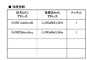
接続情報登録メッセージを受けた管理装置30は、接続情報管理部36において管理する接続情報を当該メッセージに基づき更新する。図8に示す接続情報登録メッセージに基づき更新された接続情報の一例を図9に示す。図9に示すように、接続情報は、通信端末装置のMACアドレス、接続先中継装置のMACアドレス、中継装置における無線通信で使用される周波数チャネル等から構成される。
Upon receiving the connection information registration message, the
続いて、通信端末装置(STA1)10は、通信端末装置(STA2)10との間のデータ通信の開始に先立って、通信経路効率化要求メッセージ(以下、効率化要求メッセージと略する場合もある)を管理装置30に向けて送信する(F506)。この効率化要求メッセージのデータ構成の一例を図10に示す。メッセージは、メッセージ種別、通信端末装置のMACアドレス、通信相手先となる通信端末装置のMACアドレス、通信で使用される通信帯域等から構成される。図10に示す効率化要求メッセージでは、メッセージ種別に「通信経路効率化要求」、通信端末装置(STA1)10のMACアドレスに「0x0001aabbccdd」が設定されている。また、通信相手先となる通信端末装置(STA2)10のMACアドレスには「0x0002bbccddee」、通信帯域には「10Mbps」が設定されている。 Subsequently, prior to the start of data communication with the communication terminal device (STA2) 10, the communication terminal device (STA1) 10 may be abbreviated as a communication path efficiency request message (hereinafter referred to as efficiency request message). ) To the management apparatus 30 (F506). An example of the data structure of this efficiency improvement request message is shown in FIG. The message includes a message type, a MAC address of the communication terminal device, a MAC address of the communication terminal device that is a communication partner, a communication band used for communication, and the like. In the efficiency request message shown in FIG. 10, “communication path efficiency request” is set as the message type, and “0x0001aabbccdd” is set as the MAC address of the communication terminal device (STA1) 10. In addition, “0x0002bbccddee” is set in the MAC address of the communication terminal apparatus (STA2) 10 that is the communication partner, and “10 Mbps” is set in the communication band.
効率化要求メッセージを受けた管理装置30は、通信経路判断処理を行った後、効率化要求メッセージ送信元の通信端末装置(STA1)10に向けて通信経路効率化応答メッセージ(以下、効率化応答メッセージと略する場合もある)を送信する(F507)。効率化応答メッセージのデータ構成の一例を図11に示す。効率化応答メッセージは、メッセージ種別、接続先中継装置の変更有無等から構成される。図11に示す効率化応答メッセージでは、メッセージ種別に「通信経路効率化応答」、接続先中継装置の変更有無に「接続先変更なし」が設定されている。
Upon receiving the efficiency request message, the
ここで、この通信経路判断処理の概要について簡単に説明する。図9で説明した接続情報に示す通り、通信端末装置(STA1及びSTA2)間における通信経路上には中継装置が1台だけ存在する。そして、両通信端末装置間で使用される周波数チャネルも1つだけである。また、図7及び図10で説明した中継装置情報及び効率化要求メッセージに示す通り、通信帯域についても、中継装置20の最大帯域20Mbpsを通信端末装置10における通信帯域(10Mbps)の上り及び下りで満たしている。したがって、この場合は、通信経路の変更が行われず、効率化応答メッセージの接続先変更には「変更なし」が設定される。
Here, an outline of the communication path determination process will be briefly described. As shown in the connection information described with reference to FIG. 9, there is only one relay device on the communication path between the communication terminal devices (STA1 and STA2). And there is only one frequency channel used between both communication terminal apparatuses. Further, as shown in the relay device information and the efficiency request message described in FIG. 7 and FIG. 10, the
通信経路効率化応答を受信した通信端末装置(STA1)10は、接続先となる中継装置の変更がない旨を認識した後、通信端末装置(STA2)10との間でデータ通信を開始する(F508)。 The communication terminal apparatus (STA1) 10 that has received the communication path efficiency response starts data communication with the communication terminal apparatus (STA2) 10 after recognizing that there is no change in the relay device that is the connection destination ( F508).
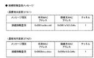
また、管理装置30は、効率化応答メッセージ送信後、通信情報管理部37において管理する通信情報を更新する。この通信情報の一例を図12に示す。図12に示すように、通信情報は、通信端末装置のMACアドレス、通信相手先となる通信端末装置のMACアドレス、使用される通信帯域等から構成される。
Further, the
図13には、通信端末装置(STA1)10と通信端末装置(STA2)10とが中継装置(AP1)20を経由して通信を行う際の処理の流れが示される。なお、ここでは、通信経路が変更されない場合について説明する。 FIG. 13 shows a processing flow when communication terminal apparatus (STA1) 10 and communication terminal apparatus (STA2) 10 communicate via relay apparatus (AP1) 20. Here, a case where the communication path is not changed will be described.
この処理が開始されると、中継装置(AP1)20は、中継装置情報を管理装置30に登録する。中継装置情報の登録処理では、中継装置20から管理装置30に向けて中継装置情報登録メッセージが送られる(F1301)。この中継装置情報登録メッセージのデータ構成の一例を図14に示す。図14には、複数の周波数チャネルを持つ中継装置20における中継装置情報登録メッセージが示される。図14に示す中継装置情報登録メッセージでは、中継装置のMACアドレスに「0x000a1b2c3d4e」、周波数チャネルに「1」、SSIDに「AP1_CH1」、最大帯域に「20Mbps」が設定されている。また、別の周波数チャネルとして、中継装置のMACアドレスに「0x000a1b2c3def」、周波数チャネルに「2」、SSIDに「AP1_CH2」、最大帯域に「20Mbps」が設定されている。
When this process is started, the relay device (AP1) 20 registers the relay device information in the
中継装置情報登録メッセージを受けた管理装置30は、中継装置情報管理部35において管理する中継装置情報を当該メッセージに基づき更新する。図14に示す中継装置情報登録メッセージに基づき更新された中継装置情報の一例を図15に示す。図15に示す中継装置情報では、中継装置(AP1)20が2つの周波数チャネルを有しているので、両情報を対応付けるために同一の中継装置番号が付与されている。
The
ここで、通信端末装置(STA1及びSTA2)は、中継装置(AP1)20に接続する(F1302、F1303)。中継装置20への接続が済むと、通信端末装置(STA1及びSTA2)各々は、管理装置30へ接続情報を登録する(F1304、F1305)。接続情報の登録処理では、通信端末装置10から管理装置30に向けて接続情報登録メッセージが送られる。この接続情報登録メッセージのデータ構成の一例を図16に示す。図16に示す接続情報登録メッセージでは、通信端末装置(STA1及びSTA2)の接続情報登録メッセージが示されている。具体的には、通信端末装置(STA1)10の接続情報として、通信端末装置のMACアドレスに「0x0001aabbccdd」、接続先中継装置のMACアドレスに「0x000a1b2c3d4e」、周波数チャネルに「1」が設定されている。また、通信端末装置(STA2)10の接続情報として、通信端末装置のMACアドレスに「0x0002bbccddee」、接続先中継装置のMACアドレスに「0x000a1b2c3def」、周波数チャネルに「2」が設定されている。
Here, the communication terminal devices (STA1 and STA2) connect to the relay device (AP1) 20 (F1302, F1303). When the connection to the
接続情報登録メッセージを受けた管理装置30は、接続情報管理部36において管理する接続情報を当該メッセージに基づき更新する。図16に示す接続情報登録メッセージに基づき更新された接続情報の一例を図17に示す。上述した通り、接続情報は、通信端末装置のMACアドレス、接続先中継装置のMACアドレス、中継装置における無線通信で使用される周波数チャネル等から構成される。
Upon receiving the connection information registration message, the
続いて、通信端末装置(STA1)10は、通信端末装置(STA2)10との間のデータ通信の開始に先立って、効率化要求メッセージを管理装置30に向けて送信する(F1306)。この効率化要求メッセージのデータ構成の一例を図18に示す。図18に示す効率化要求メッセージでは、通信端末装置(STA1)10からの効率化要求メッセージとして、通信端末装置(STA1)10のMACアドレスに「0x0001aabbccdd」が設定されている。また、通信相手先となる通信端末装置(STA2)10のMACアドレスに「0x0002bbccddee」、通信帯域に「15Mbps」が設定されている。 Subsequently, prior to the start of data communication with the communication terminal device (STA2) 10, the communication terminal device (STA1) 10 transmits an efficiency request message to the management device 30 (F1306). An example of the data structure of this efficiency improvement request message is shown in FIG. In the efficiency request message shown in FIG. 18, “0x0001aabbccdd” is set in the MAC address of the communication terminal apparatus (STA1) 10 as the efficiency request message from the communication terminal apparatus (STA1) 10. Further, “0x0002bbccddee” is set in the MAC address of the communication terminal device (STA2) 10 which is the communication partner, and “15 Mbps” is set in the communication band.
効率化要求メッセージを受けた管理装置30は、通信経路判断処理を行った後、効率化要求メッセージ送信元の通信端末装置(STA1)10に向けて効率化応答メッセージを送信する(F1307)。ここで送信される効率化応答メッセージは、図11同様の内容となり、接続先変更なしが設定される。
Upon receiving the efficiency request message, the
ここで、この通信経路判断処理の概要について簡単に説明する。図15で説明した中継装置情報、図17で説明した接続情報に示す通り、通信端末装置(STA1及びSTA2)間における通信経路上には中継装置が1台だけ存在する。そして、両通信端末装置間では、チャネル1とチャネル2の2つの周波数チャネルが使用される。すなわち、通信端末装置(STA1)10と中継装置20との間をチャネル1で通信し、通信端末装置(STA2)10と中継装置20との間をチャネル2で通信している。通信帯域については、図15で説明した中継装置情報、図18で説明した効率化要求メッセージに示す通り、チャネル1及びチャネル2のそれぞれについて中継装置20の最大帯域20Mbpsで満たされる。したがって、この場合は、通信経路の変更が行われず、効率化応答メッセージの接続先変更には「変更なし」が設定される。
Here, an outline of the communication path determination process will be briefly described. As shown in the relay device information described in FIG. 15 and the connection information described in FIG. 17, there is only one relay device on the communication path between the communication terminal devices (STA1 and STA2). Between the two communication terminal apparatuses, two frequency channels of
通信経路効率化応答を受信した通信端末装置(STA1)10では、接続先となる中継装置の変更がないことを認識した後、通信端末装置(STA2)10との間でデータ通信を開始する(F1308)。 The communication terminal device (STA1) 10 that has received the communication path efficiency response starts data communication with the communication terminal device (STA2) 10 after recognizing that there is no change in the relay device as the connection destination ( F1308).
また、管理装置30は、効率化応答メッセージ送信後、通信情報管理部37において管理する通信情報を更新する。この通信情報の一例を図19に示す。上述した通り、通信情報は、通信端末装置のMACアドレス、通信相手先となる通信端末装置のMACアドレス、使用される通信帯域等から構成される。
Further, the
図20には、通信端末装置(STA1)10と通信端末装置(STA2)10とが中継装置(AP2)20を経由して通信を行う際の処理の流れが示される。なお、ここでは、通信経路が変更される場合について説明する。 FIG. 20 shows a processing flow when communication terminal apparatus (STA1) 10 and communication terminal apparatus (STA2) 10 communicate via relay apparatus (AP2) 20. Here, a case where the communication path is changed will be described.
この処理が開始されると、中継装置(AP1)20は、中継装置情報を管理装置30に登録する。中継装置情報の登録処理では、中継装置20から管理装置30に向けて中継装置情報登録メッセージが送られる(F2001)。このF2001の処理における中継装置情報登録メッセージは、図14同様の内容となる。
When this process is started, the relay device (AP1) 20 registers the relay device information in the
また、中継装置(AP2)20においても、中継装置情報の登録処理が実施される(F2002)。このF2002の処理における中継装置情報登録メッセージのデータ構成の一例を図21に示す。図21に示す中継装置情報登録メッセージでは、中継装置のMACアドレスに「0x000b6f7e8d9c」、周波数チャネルに「2」、SSIDに「AP2_CH2」、最大帯域に「20Mbps」が設定されている。 Also, the relay device information registration process is performed in the relay device (AP2) 20 (F2002). An example of the data structure of the relay device information registration message in the process of F2002 is shown in FIG. In the relay device information registration message shown in FIG. 21, “0x000b6f7e8d9c” is set as the MAC address of the relay device, “2” is set as the frequency channel, “AP2_CH2” is set as the SSID, and “20 Mbps” is set as the maximum bandwidth.
中継装置情報登録メッセージを受けた管理装置30は、中継装置情報管理部35において管理する中継装置情報をこれら中継装置(AP1及びAP2)から送られてきたメッセージに基づき更新する。図14及び図21に示す中継装置情報登録メッセージに基づき更新された中継装置情報の一例を図22に示す。図22に示す中継装置情報では、中継装置(AP1)20が2つの周波数チャネルを有しているので、当該中継装置の各チャネルを対応付けるために同一の中継装置番号が付与されている。
Upon receiving the relay device information registration message, the
ここで、通信端末装置(STA1)10は、中継装置(AP1)20に接続し(F2003)、通信端末装置(STA2)10は、中継装置(AP2)20に接続する(F2004)。中継装置20への接続が済むと、通信端末装置(STA1及びSTA2)各々は、管理装置30へ接続情報を登録する(F2005、F2006)。接続情報の登録処理では、通信端末装置10から管理装置30に向けて接続情報登録メッセージが送られる。この接続情報登録メッセージのデータ構成の一例を図23に示す。図23に示す接続情報登録メッセージでは、通信端末装置(STA1及びSTA2)の接続情報登録メッセージが示されている。具体的には、通信端末装置(STA1)10の接続情報として、通信端末装置のMACアドレスに「0x0001aabbccdd」、接続先中継装置のMACアドレスに「0x000a1b2c3d4e」、周波数チャネルに「1」が設定されている。また、通信端末装置(STA2)10の接続情報として、通信端末装置のMACアドレスに「0x0002bbccddee」、接続先中継装置のMACアドレスに「0x000b6f7e8d9c」、周波数チャネルに「2」が設定されている。
Here, the communication terminal device (STA1) 10 is connected to the relay device (AP1) 20 (F2003), and the communication terminal device (STA2) 10 is connected to the relay device (AP2) 20 (F2004). When the connection to the
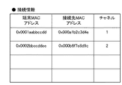
接続情報登録メッセージを受けた管理装置30は、接続情報管理部36において管理する接続情報を当該メッセージに基づき更新する。図23に示す接続情報登録メッセージに基づき更新された接続情報の一例を図24に示す。上述した通り、接続情報は、通信端末装置のMACアドレス、接続先中継装置のMACアドレス、中継装置における無線通信で使用される周波数チャネル等から構成される。
Upon receiving the connection information registration message, the
続いて、通信端末装置(STA1)10は、通信端末装置(STA2)10との間のデータ通信の開始に先立って、効率化要求メッセージを管理装置30に向けて送信する(F2007)。このF2007の処理における効率化要求メッセージは、図10同様の内容となる。 Subsequently, prior to the start of data communication with the communication terminal device (STA2) 10, the communication terminal device (STA1) 10 transmits an efficiency request message to the management device 30 (F2007). The efficiency improvement request message in the processing of F2007 has the same contents as in FIG.
効率化要求メッセージを受けた管理装置30は、通信経路判断処理を行った後、効率化要求メッセージ送信元の通信端末装置(STA1)10に向けて効率化応答メッセージを送信する(F2008)。効率化応答メッセージのデータ構成の一例を図25に示す。図25に示す効率化応答メッセージでは、接続先変更ありが設定されている。
Upon receiving the efficiency request message, the
ここで、この通信経路判断処理の概要について簡単に説明する。図22で説明した中継装置情報、図24で説明した接続情報に示す通り、通信端末装置(STA1及びSTA2)間における通信経路上には中継装置が2台存在する。そして、両通信端末装置間では、チャネル1とチャネル2の2つの周波数チャネルが使用される。そこで、通信端末装置(STA1及びSTA2)間で経由する中継装置が1台になるべく通信経路の変更が行われる。ここで、通信帯域については、図22で説明した中継装置情報、図10で説明した効率化要求メッセージに示す通り、中継装置(AP1及びAP2)のいずれを接続先とした場合であっても、両装置間の通信帯域は中継装置20の最大帯域で満たされる。したがって、チャネル数の少ない中継装置(AP2)20が経由先として選ばれ、効率化要求メッセージ送信元の通信端末装置(STA1)10の接続先となる中継装置が変更される。そのため、効率化応答メッセージの接続先変更には「変更あり」が設定される。なお、チャネル数の少ない中継装置を経由先として優先させて選ぶのは、チャネル数が多い中継装置の場合、チャネル数の少ない中継装置よりもチャネル切替が頻繁に行なわれる可能性が高いためである。チャネル切替時には、中継装置の処理に多大な負荷がかかることが多く、この負荷により通信速度が低下してしまう虞がある。
Here, an outline of the communication path determination process will be briefly described. As shown in the relay device information described in FIG. 22 and the connection information described in FIG. 24, there are two relay devices on the communication path between the communication terminal devices (STA1 and STA2). Between the two communication terminal apparatuses, two frequency channels of
通信経路効率化応答を受信した通信端末装置(STA1)10では、接続先となる中継装置の変更がある旨を認識するとともに、管理装置30から接続変更指示メッセージを受信する(F2009)。この接続変更指示メッセージのデータ構成の一例を図26に示す。接続変更指示メッセージは、メッセージ種別、中継装置のMACアドレス、中継装置の無線通信で使用する周波数チャネル及びSSID等から構成される。図26に示す接続変更指示メッセージでは、メッセージ種別に「接続変更指示」、中継装置のMACアドレスに「0x000b6f7e8d9c」、周波数チャネルに「2」、SSIDに「AP2_CH2」が設定されている。 The communication terminal apparatus (STA1) 10 that has received the communication path efficiency response recognizes that there is a change in the relay apparatus that is the connection destination, and receives a connection change instruction message from the management apparatus 30 (F2009). An example of the data structure of the connection change instruction message is shown in FIG. The connection change instruction message includes a message type, a MAC address of the relay device, a frequency channel used for wireless communication of the relay device, an SSID, and the like. In the connection change instruction message shown in FIG. 26, “connection change instruction” is set as the message type, “0x000b6f7e8d9c” is set as the MAC address of the relay device, “2” is set as the frequency channel, and “AP2_CH2” is set as the SSID.
この接続変更指示メッセージを受けた通信端末装置(STA1)10は、中継装置(AP1)20との通信を切断し(F2010)、中継装置(AP2)20に接続する(F2011)。その後、通信端末装置(STA1)10は、通信端末装置(STA2)10との間でデータ通信を開始する(F2012)。 Receiving this connection change instruction message, the communication terminal device (STA1) 10 disconnects communication with the relay device (AP1) 20 (F2010) and connects to the relay device (AP2) 20 (F2011). Thereafter, the communication terminal apparatus (STA1) 10 starts data communication with the communication terminal apparatus (STA2) 10 (F2012).
また、管理装置30は、効率化応答メッセージ送信後、通信情報管理部37において管理する通信情報を更新する。この通信情報は、図12同様の内容となる。更に、上述した通信経路の変更が行なわれた後、管理装置30の接続情報管理部36において管理される接続情報の一例を図27に示す。図27に示す接続情報では、図24に示す通信経路変更前の接続情報と比べて、接続先となる中継装置のMACアドレスが変更されている。すなわち、通信端末装置(STA1)10の接続先が中継装置(AP1)20から中継装置(AP2)20に変更されている。
Further, the
図28には、通信端末装置(STA1)10と通信端末装置(STA2)10とが中継装置(AP1及びAP2)を経由して通信を行う際の処理の流れが示される。なお、ここでは、通信経路が変更される場合について説明する。 FIG. 28 shows the flow of processing when the communication terminal device (STA1) 10 and the communication terminal device (STA2) 10 communicate via the relay devices (AP1 and AP2). Here, a case where the communication path is changed will be described.
この処理が開始されると、中継装置(AP1)20は、中継装置情報を管理装置30に登録する。中継装置情報の登録処理では、中継装置20から管理装置30に向けて中継装置情報登録メッセージが送られる(F2801)。このF2801の処理における中継装置情報登録メッセージは、図14同様の内容となる。
When this process is started, the relay device (AP1) 20 registers the relay device information in the
また、中継装置(AP2)20においても、中継装置情報の登録処理が実施される(F2802)。このF2802の処理における中継装置情報登録メッセージは、図21同様の内容となる。 Also, the relay device information registration process is performed in the relay device (AP2) 20 (F2802). The relay device information registration message in the process of F2802 has the same contents as in FIG.
中継装置情報登録メッセージを受けた管理装置30は、中継装置情報管理部35において管理する中継装置情報をこれら中継装置(AP1及びAP2)から送られてきたメッセージに基づき更新する。この中継装置情報は、図22同様の内容となる。
Upon receiving the relay device information registration message, the
ここで、通信端末装置(STA1)10は、中継装置(AP1)20に接続し(F2803)、通信端末装置(STA2)10は、中継装置(AP2)20に接続する(F2804)。中継装置20への接続が済むと、通信端末装置(STA1及びSTA2)各々は、管理装置30へ接続情報を登録する(F2805、F2806)。接続情報の登録処理では、通信端末装置10から管理装置30に向けて接続情報登録メッセージが送られる。この接続情報登録メッセージは、図23同様の内容となる。また、接続情報登録メッセージを受けた管理装置30は、接続情報管理部36において管理する接続情報を当該メッセージに基づき更新する。この接続情報は、図24同様の内容となる。
Here, the communication terminal device (STA1) 10 is connected to the relay device (AP1) 20 (F2803), and the communication terminal device (STA2) 10 is connected to the relay device (AP2) 20 (F2804). When the connection to the
続いて、通信端末装置(STA1)10は、通信端末装置(STA2)10との間のデータ通信の開始に先立って、効率化要求メッセージを管理装置30に向けて送信する(F2807)。このF2807の処理における効率化要求メッセージは、図18同様の内容となる。 Subsequently, prior to the start of data communication with the communication terminal apparatus (STA2) 10, the communication terminal apparatus (STA1) 10 transmits an efficiency request message to the management apparatus 30 (F2807). The efficiency improvement request message in the processing of F2807 has the same contents as in FIG.
効率化要求メッセージを受けた管理装置30は、通信経路判断処理を行った後、効率化要求メッセージ送信元の通信端末装置(STA1)10に向けて効率化応答メッセージを送信する(F2808)。ここで送信される効率化応答メッセージは、図11同様の内容となり、接続先変更なしが設定されている。
Upon receiving the efficiency request message, the
ここで、この通信経路判断処理の概要について簡単に説明する。図22で説明した中継装置情報、図24で説明した接続情報に示す通り、通信端末装置(STA1及びSTA2)間における通信経路上には中継装置が2台存在する。そして、両通信端末装置間では、チャネル1とチャネル2の2つの周波数チャネルが使用される。そこで、通信端末装置(STA1及びSTA2)間で経由する中継装置が1台になるべく通信経路の変更が行われる。ここで、通信帯域については、図22で説明した中継装置情報、図18で説明した効率化要求メッセージに示す通り、中継装置(AP2)20を接続先とした場合、両装置間の通信帯域が中継装置20の最大帯域を越えてしまう。したがって、中継装置(AP1)20が経由先として選ばれ、効率化要求メッセージ送信元の通信端末装置(STA1)10の接続先となる中継装置は変更されない。そのため、効率化応答メッセージの接続先変更には「変更なし」が設定される。
Here, an outline of the communication path determination process will be briefly described. As shown in the relay device information described in FIG. 22 and the connection information described in FIG. 24, there are two relay devices on the communication path between the communication terminal devices (STA1 and STA2). Between the two communication terminal apparatuses, two frequency channels of
上述した通信経路判断処理の結果、通信端末装置(STA2)10の接続先が中継装置(AP1)20となるように通信経路の変更が行われる。そこで、管理装置30は、通信端末装置(STA2)10に向けて接続変更指示メッセージを送信する(F2809)。接続変更指示メッセージのデータ構成の一例を図29に示す。図29に示す接続変更指示メッセージでは、メッセージ種別に「接続変更指示」、中継装置のMACアドレスに「0x000a1b2c3def」、周波数チャネルに「2」、SSIDに「AP1_CH2」が設定されている。
As a result of the communication path determination process described above, the communication path is changed so that the connection destination of the communication terminal apparatus (STA2) 10 is the relay apparatus (AP1) 20. Therefore, the
接続変更指示メッセージを受けた通信端末装置(STA2)10は、中継装置(AP2)20との通信を切断し(F2810)、中継装置(AP1)20に接続する(F2811)。その後、通信端末装置(STA2)10は、通信端末装置(STA1)10との間でデータ通信を開始する(F2812)。 Receiving the connection change instruction message, the communication terminal apparatus (STA2) 10 disconnects communication with the relay apparatus (AP2) 20 (F2810) and connects to the relay apparatus (AP1) 20 (F2811). Thereafter, the communication terminal apparatus (STA2) 10 starts data communication with the communication terminal apparatus (STA1) 10 (F2812).
また、管理装置30は、効率化応答メッセージ送信後、通信情報管理部37において管理する通信情報を更新する。この通信情報は、図19同様の内容となる。更に、上述した通信経路の変更が行なわれた後、管理装置30の接続情報管理部36において管理される接続情報は、図17同様となる。
Further, the
図30には、通信端末装置(STA1及びSTA2)が中継装置(AP1及びAP2)を経由して通信を行う際の処理の流れが示される。また、図30では更に、通信端末装置(STA3及びSTA4)も通信を行なうため中継装置(AP1)に接続する。なお、ここでは、通信経路が変更される場合について説明する。 FIG. 30 shows a flow of processing when communication terminal apparatuses (STA1 and STA2) perform communication via relay apparatuses (AP1 and AP2). Further, in FIG. 30, the communication terminal devices (STA3 and STA4) are also connected to the relay device (AP1) for communication. Here, a case where the communication path is changed will be described.
この処理が開始されると、中継装置(AP1)20は、中継装置情報を管理装置30に登録する。中継装置情報の登録処理では、中継装置20から管理装置30に向けて中継装置情報登録メッセージが送られる(F3001)。このF3001の処理における中継装置情報登録メッセージは、図14同様の内容となる。
When this process is started, the relay device (AP1) 20 registers the relay device information in the
また、中継装置(AP2)20においても、中継装置情報の登録処理が実施される(F3002)。このF3002の処理における中継装置情報登録メッセージは、図21同様の内容となる。 Also, the relay device information registration process is performed in the relay device (AP2) 20 (F3002). The relay device information registration message in the process of F3002 has the same contents as in FIG.
中継装置情報登録メッセージを受けた管理装置30は、中継装置情報管理部35において管理する中継装置情報をこれら中継装置(AP1及びAP2)から送られてきたメッセージに基づき更新する。この中継装置情報は、図22同様の内容となる。
Upon receiving the relay device information registration message, the
ここで、通信端末装置(STA1)10は、中継装置(AP1)20に接続し(F3003)、通信端末装置(STA2)10は、中継装置(AP2)20に接続する(F3004)。中継装置20への接続が済むと、通信端末装置(STA1及びSTA2)各々は、管理装置30へ接続情報を登録する(F3005、F3006)。接続情報の登録処理では、通信端末装置10から管理装置30に向けて接続情報登録メッセージが送られる。この接続情報登録メッセージは、図23同様の内容となる。また、接続情報登録メッセージを受けた管理装置30は、接続情報管理部36において管理する接続情報を当該メッセージに基づき更新する。この接続情報は、図24同様の内容となる。
Here, the communication terminal apparatus (STA1) 10 is connected to the relay apparatus (AP1) 20 (F3003), and the communication terminal apparatus (STA2) 10 is connected to the relay apparatus (AP2) 20 (F3004). When the connection to the
接続情報登録メッセージを送信した後、通信端末装置(STA1)10は、通信端末装置(STA2)10との間のデータ通信の開始に先立って、通信経路の効率化要求ではなく、通信情報登録メッセージを管理装置30に向けて送信する(F3007)。通信情報登録メッセージのデータ構成の一例を図31に示す。通信情報登録メッセージは、メッセージ種別、通信端末装置のMACアドレス、通信相手先となる通信端末装置のMACアドレス、通信で使用される通信帯域等から構成される。図31に示す通信情報登録メッセージでは、メッセージ種別に「通信情報登録」、通信端末装置(STA1)10のMACアドレスに「0x0001aabbccdd」が設定されている。また、通信相手先の通信端末装置(STA2)10のMACアドレスには「0x0002bbccddee」、通信帯域には「10Mbps」が設定されている。 After transmitting the connection information registration message, the communication terminal apparatus (STA1) 10 prior to the start of data communication with the communication terminal apparatus (STA2) 10 is not a communication path efficiency request but a communication information registration message. Is transmitted to the management apparatus 30 (F3007). An example of the data structure of the communication information registration message is shown in FIG. The communication information registration message includes a message type, a MAC address of a communication terminal device, a MAC address of a communication terminal device that is a communication partner, a communication band used for communication, and the like. In the communication information registration message shown in FIG. 31, “communication information registration” is set as the message type, and “0x0001aabbccdd” is set as the MAC address of the communication terminal apparatus (STA1) 10. In addition, “0x0002bbccddee” is set in the MAC address of the communication terminal apparatus (STA2) 10 of the communication partner, and “10 Mbps” is set in the communication band.
通信情報を登録した後、通信端末装置(STA1)10は、通信端末装置(STA2)10との間でデータ通信を開始する(F3008)。ここで更に、通信端末装置(STA3及びSTA4)が中継装置(AP1)20に接続する(F3009、F3010)。中継装置20への接続が済むと、通信端末装置(STA3及びSTA4)各々は、管理装置30へ接続情報を登録する(F3011、F3012)。接続情報の登録処理では、通信端末装置10から管理装置30に向けて接続情報登録メッセージが送られる。この接続情報登録メッセージのデータ構成の一例を図32に示す。図32に示す接続情報登録メッセージでは、通信端末装置(STA3及びSTA4)の接続情報登録メッセージが示されている。具体的には、通信端末装置(STA3)10の接続情報として、通信端末装置のMACアドレスに「0x0003ccddeeff」、接続先中継装置のMACアドレスに「0x000a1b2c3d4e」、周波数チャネルに「1」が設定されている。また、通信端末装置(STA4)10の接続情報として、通信端末装置のMACアドレスに「0x0004ddeeffaa」、接続先中継装置のMACアドレスに「0x000a1b2c3def」、周波数チャネルに「2」が設定されている。
After registering the communication information, the communication terminal apparatus (STA1) 10 starts data communication with the communication terminal apparatus (STA2) 10 (F3008). Further, the communication terminal devices (STA3 and STA4) connect to the relay device (AP1) 20 (F3009, F3010). When the connection to the
続いて、通信端末装置(STA3)10は、通信端末装置(STA4)10との間のデータ通信の開始に先立って、効率化要求メッセージを管理装置30に向けて送信する(F3013)。このF3013の処理における効率化要求メッセージのデータ構成の一例を図33に示す。図33に示す効率化要求メッセージでは、通信端末装置(STA3)10のMACアドレスに「0x0003ccddeeff」、通信相手先となる通信端末装置(STA4)10のMACアドレスに「0x0004ddeeffaa」が設定されている。また、通信帯域には「15Mbps」が設定されている。 Subsequently, prior to the start of data communication with the communication terminal device (STA4) 10, the communication terminal device (STA3) 10 transmits an efficiency request message to the management device 30 (F3013). An example of the data structure of the efficiency improvement request message in the processing of F3013 is shown in FIG. In the efficiency improvement request message shown in FIG. 33, “0x0003ccddeeff” is set in the MAC address of the communication terminal device (STA3) 10, and “0x0004ddefeaa” is set in the MAC address of the communication terminal device (STA4) 10 that is the communication partner. In addition, “15 Mbps” is set as the communication band.
効率化要求メッセージを受けた管理装置30は、通信経路判断処理を行った後、効率化要求メッセージ送信元の通信端末装置(STA3)10に向けて効率化応答メッセージを送信する(F3014)。ここで送信される効率化応答メッセージは、図11同様の内容となり、接続先変更なしが設定される。
Upon receiving the efficiency request message, the
ここで、この通信経路判断処理の概要について簡単に説明する。図22で説明した中継装置情報、図32で説明した接続情報登録メッセージに示す通り、通信端末装置(STA3及びSTA4)間の通信経路上に存在する中継装置は1台だけとなる。そのため、当該中継装置(AP1)20に接続される他の通信端末装置10に対して通信経路の変更判断がなされる。この場合、図22で説明した中継装置情報、図24で説明した接続情報に示す通り、通信端末装置(STA1及びSTA2)間における通信経路上には中継装置が2台存在する。そして、両通信端末装置間では、チャネル1とチャネル2の2つの周波数チャネルが使用される。そこで、通信端末装置(STA1及びSTA2)間の通信経路上における中継装置が1台になるべく、またその通信に際して使用される周波数チャネルが1つになるべく通信経路の変更が行われる。ここで、通信帯域については、図22で説明した中継装置情報、図31で説明した通信情報登録メッセージに示す通り、中継装置(AP1及びAP2)のいずれを接続先とした場合であっても、両装置間の通信帯域は中継装置20の最大帯域で満たされる。したがって、チャネル数の少ない中継装置(AP2)20が経由先として選ばれ、効率化要求メッセージ送信元の通信端末装置(STA3)10の接続先となる中継装置は変更されない。そのため、効率化応答メッセージの接続先変更には「変更なし」が設定される。なお、チャネル数の少ない中継装置を経由先として優先させて選ぶのは、上述した通り、チャネル切替による通信速度の低下を避けるためである。
Here, an outline of the communication path determination process will be briefly described. As shown in the relay device information described in FIG. 22 and the connection information registration message described in FIG. 32, only one relay device exists on the communication path between the communication terminal devices (STA3 and STA4). Therefore, the communication path change determination is made for the other
通信経路判断処理の結果、通信端末装置(STA1)10の接続先が中継装置(AP2)20となるように通信経路の変更が行われる。そこで、管理装置30は、通信端末装置(STA1)10に向けて接続変更指示メッセージを送信する(F3015)。この接続変更指示メッセージは、図26同様の内容となる。
As a result of the communication path determination process, the communication path is changed so that the connection destination of the communication terminal apparatus (STA1) 10 becomes the relay apparatus (AP2) 20. Therefore, the
接続変更指示メッセージを受けた通信端末装置(STA1)10は、中継装置(AP1)20との通信を切断し(F3016)、中継装置(AP2)20に接続する(F3017)。その後、通信端末装置(STA1)10は、通信端末装置(STA2)10との間におけるデータ通信を再開する(F3018)。また、通信端末装置(STA3)10と通信端末装置(STA4)10との間におけるデータ通信は、中継装置(AP1)20を経由して開始される(F3019)。 Receiving the connection change instruction message, the communication terminal apparatus (STA1) 10 disconnects the communication with the relay apparatus (AP1) 20 (F3016) and connects to the relay apparatus (AP2) 20 (F3017). Thereafter, the communication terminal apparatus (STA1) 10 resumes data communication with the communication terminal apparatus (STA2) 10 (F3018). Data communication between the communication terminal device (STA3) 10 and the communication terminal device (STA4) 10 is started via the relay device (AP1) 20 (F3019).
また、管理装置30は、効率化応答メッセージ送信後、通信情報管理部37において管理する通信情報を更新する。この通信情報の一例を図34に示す。上述した通り、通信情報は、通信端末装置のMACアドレス、通信相手先となる通信端末装置のMACアドレス、使用される通信帯域等から構成される。ここで、上述した通信経路の変更が行なわれた後、管理装置30の接続情報管理部36において管理される接続情報の一例を図35に示す。上述した通り、接続情報は、通信端末装置のMACアドレス、接続先中継装置のMACアドレス、中継装置における無線通信で使用される周波数チャネル等から構成される。
Further, the
図36には、通信端末装置(STA3及びSTA4)間が中継装置(AP1)20を経由して通信を行い、通信端末装置(STA5及びSTA6)間が中継装置(AP2)20を経由して通信を行なう際の処理の流れが示される。また、図36では、ネットワークの構成に中継装置(AP3)20が含まれる。なお、ここでは、通信経路が変更される場合について説明する。 In FIG. 36, communication terminal apparatuses (STA3 and STA4) communicate with each other via the relay apparatus (AP1) 20, and communication terminal apparatuses (STA5 and STA6) communicate with each other via the relay apparatus (AP2) 20. The flow of processing when performing is shown. In FIG. 36, the relay apparatus (AP3) 20 is included in the network configuration. Here, a case where the communication path is changed will be described.
この処理が開始されると、中継装置(AP1)20は、中継装置情報を管理装置30に登録する。中継装置情報の登録処理では、中継装置20から管理装置30に向けて中継装置情報登録メッセージが送られる(F3601)。このF3601の処理における中継装置情報登録メッセージは、図14同様の内容となる。
When this process is started, the relay device (AP1) 20 registers the relay device information in the
また、中継装置(AP2及びAP3)20においても、中継装置情報の登録処理が実施される(F3602、F3603)。このF3602の処理における中継装置情報登録メッセージは、図21同様の内容となる。ここで、F3603の処理における中継装置情報登録メッセージのデータ構成の一例を図37に示す。図37に示す中継装置情報登録メッセージでは、中継装置のMACアドレスに「0x000c3d4e5f6a」、周波数チャネルに「3」、SSIDに「AP3_CH3」、最大帯域に「20Mbps」が設定されている。 Also, the relay device information registration process is performed in the relay devices (AP2 and AP3) 20 (F3602, F3603). The relay device information registration message in the process of F3602 has the same contents as in FIG. Here, FIG. 37 shows an example of the data configuration of the relay device information registration message in the process of F3603. In the relay device information registration message shown in FIG. 37, “0x000c3d4e5f6a” is set for the MAC address of the relay device, “3” is set for the frequency channel, “AP3_CH3” is set for the SSID, and “20 Mbps” is set for the maximum bandwidth.
中継装置情報登録メッセージを受けた管理装置30は、中継装置情報管理部35において管理する中継装置情報を更新する。中継装置情報の一例を図38に示す。中継装置情報は、上述した通り、中継装置のMACアドレス、中継装置における無線通信で使用される周波数チャネル及びSSID、中継装置における無線通信で確保可能な最大帯域等から構成される。中継装置情報には更に、複数の周波数チャネルを有する中継装置を対応付けるための中継装置番号も含まれる。
The
ここで、通信端末装置(STA1)10は、中継装置(AP1)20へ接続し(F3604)、通信端末装置(STA2)10は、中継装置(AP2)20へ接続する(F3605)。更に、通信端末装置(STA3及びSTA4)は、中継装置(AP1)20へ接続し(F3606)、通信端末装置(STA5及びSTA6)は、中継装置(AP2)20へ接続する(F3607)。 Here, the communication terminal apparatus (STA1) 10 is connected to the relay apparatus (AP1) 20 (F3604), and the communication terminal apparatus (STA2) 10 is connected to the relay apparatus (AP2) 20 (F3605). Further, the communication terminal devices (STA3 and STA4) are connected to the relay device (AP1) 20 (F3606), and the communication terminal devices (STA5 and STA6) are connected to the relay device (AP2) 20 (F3607).
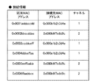
中継装置への接続が済むと、通信端末装置(STA1〜STA6)各々は、管理装置30へ接続情報を登録する(F3608、F3609、F3610、F3611)。接続情報の登録処理では、通信端末装置10から管理装置30に向けて接続情報登録メッセージが送られる。この通信端末装置(STA1〜STA6)各々における接続情報登録メッセージのデータ構成の一例を図39に示す。図39には、通信端末装置(STA1)10の接続情報として、通信端末装置のMACアドレスに「0x0001aabbccdd」、接続先中継装置のMACアドレスに「0x000a1b2c3d4e」、周波数チャネルに「1」が設定されている。また、通信端末装置(STA2)10の接続情報として、通信端末装置のMACアドレスに「0x0002bbccddee」、接続先中継装置のMACアドレスに「0x000b6f7e8d9c」、周波数チャネルに「2」が設定されている。また、通信端末装置(STA3)10の接続情報として、通信端末装置のMACアドレスに「0x0003ccddeeff」、接続先中継装置のMACアドレスに「0x000a1b2c3d4e」、周波数チャネルに「1」が設定されている。また、通信端末装置(STA4)10の接続情報として、通信端末装置のMACアドレスに「0x0004ddeeffaa」、接続先中継装置のMACアドレスに「0x000a1b2c3d4e」、周波数チャネルに「1」が設定されている。また、通信端末装置(STA5)10の接続情報として、通信端末装置のMACアドレスに「0x0005eeffaabb」、接続先中継装置のMACアドレスに「0x000b6f7e8d9c」、周波数チャネルに「2」が設定されている。また、通信端末装置(STA6)10の接続情報として、通信端末装置のMACアドレスに「0x0006ffaabbcc」、接続先中継装置のMACアドレスに「0x000b6f7e8d9c」、周波数チャネルに「2」が設定されている。
When the connection to the relay device is completed, each of the communication terminal devices (STA1 to STA6) registers connection information in the management device 30 (F3608, F3609, F3610, F3611). In the connection information registration process, a connection information registration message is sent from the
接続情報登録メッセージを受けた管理装置30は、接続情報管理部36において管理する接続情報を当該メッセージに基づき更新する。図39に示す接続情報登録メッセージに基づき更新された接続情報の一例を図40に示す。上述した通り、接続情報は、通信端末装置のMACアドレス、接続先中継装置のMACアドレス、中継装置における無線通信で使用される周波数チャネル等から構成される。
Upon receiving the connection information registration message, the
続いて、通信端末装置(STA3)10は、通信端末装置(STA4)10との間のデータ通信の開始に先立って、通信経路の効率化要求ではなく、通信情報登録メッセージを管理装置30に向けて送信する(F3612)。また、通信端末装置(STA5)10も同様に、通信端末装置(STA6)10との間のデータ通信の開始に先立って、通信経路の効率化要求ではなく、通信情報登録メッセージを管理装置30に向けて送信する(F3613)。このF3612及びF3613の処理における通信情報登録メッセージのデータ構成の一例を図41に示す。図41に示す通信情報登録メッセージでは、通信端末装置(STA3及びSTA5)の通信情報登録メッセージが示されている。具体的には、通信端末装置(STA3)10から送信された通信情報登録メッセージとして、通信端末装置(STA3)10のMACアドレスに「0x0003ccddeeff」が設定されている。更に、通信相手先となる通信端末装置(STA4)10のMACアドレスには「0x0004ddeeffaa」、通信帯域には「10Mbps」が設定されている。また、通信端末装置(STA5)10から送信された通信情報登録メッセージとして、通信端末装置(STA5)10のMACアドレスに「0x0005eeffaabb」が設定されている。更に、通信相手先となる通信端末装置(STA6)10のMACアドレスには「0x0006ffaabbcc」、通信帯域には「10Mbps」が設定されている。
Subsequently, prior to the start of data communication with the communication terminal device (STA4) 10, the communication terminal device (STA3) 10 sends a communication information registration message to the
通信情報を登録した後、通信端末装置(STA3及びSTA4)間でデータ通信が開始される(F3614)。また、通信端末装置(STA5及びSTA6)間でもデータ通信が開始される(F3615)。このとき、管理装置30の通信情報管理部37において管理される通信情報の一例を図42に示す。上述した通り、通信情報は、通信端末装置のMACアドレス、通信相手先となる通信端末装置のMACアドレス、使用される通信帯域等から構成される。
After registering the communication information, data communication is started between the communication terminal devices (STA3 and STA4) (F3614). Data communication is also started between the communication terminal devices (STA5 and STA6) (F3615). At this time, an example of communication information managed by the communication
ここで、通信端末装置(STA1)10は、効率化要求メッセージを管理装置30に向けて送信する(F3616)。このF3616の処理における効率化要求メッセージは、図10同様の内容となる。 Here, the communication terminal apparatus (STA1) 10 transmits an efficiency request message to the management apparatus 30 (F3616). The efficiency improvement request message in the processing of F3616 has the same content as FIG.
効率化要求メッセージを受けた管理装置30は、通信経路判断処理を行った後、効率化要求メッセージ送信元の通信端末装置(STA1)10に向けて効率化応答メッセージを送信する(F3617)。ここで送信される効率化応答メッセージは、図25同様の内容となり、接続先変更ありが設定されている。
Upon receiving the efficiency request message, the
ここで、この通信経路判断処理の概要について簡単に説明する。図38で説明した中継装置情報、図40で説明した接続情報に示す通り、通信端末装置(STA1及びSTA2)間における通信経路上には中継装置が2台存在する。そして、両通信端末装置間では、チャネル1とチャネル2の2つの周波数チャネルが使用される。そこで、通信端末装置(STA1及びSTA2)間で経由する中継装置が1台になるべく、またその通信に際して使用される周波数チャネルが1つになるべく通信経路の変更が行われる。ここで、通信端末装置(STA1及びSTA2)間で経由する中継装置(AP1及びAP2)を比較してみると、中継装置(AP2)20の方がチャネル数が少ないため、中継装置(AP2)20が接続先の候補として選ばれる。しかし、中継装置(AP2)20は、通信端末装置(STA5及びSTA6)間の通信に利用されており、通信帯域に余裕(所定以上の空き)がない。したがって、通信帯域に余裕のある中継装置(AP3)20が経由先として選ばれ、効率化要求メッセージ送信元の通信端末装置(STA1)10の接続先となる中継装置が変更される。そのため、効率化応答メッセージの接続先変更には「変更あり」が設定される。
Here, an outline of the communication path determination process will be briefly described. As shown in the relay apparatus information described in FIG. 38 and the connection information described in FIG. 40, there are two relay apparatuses on the communication path between the communication terminal apparatuses (STA1 and STA2). Between the two communication terminal apparatuses, two frequency channels of
通信経路効率化応答の送信後、管理装置30は、通信端末装置(STA1及びSTA2)に向けて接続変更指示メッセージを送信する(F3618、F3619)。この接続変更指示メッセージのデータ構成の一例を図43に示す。図43に示す接続変更指示メッセージでは、メッセージ種別に「接続変更指示」、中継装置のMACアドレスに「0x000c3d4e5f6a」、周波数チャネルに「3」、SSIDに「AP3_CH3」が設定されている。
After transmitting the communication path efficiency response, the
この接続変更指示メッセージを受けた通信端末装置(STA1)10は、中継装置(AP1)20との通信を切断し(F3620)、中継装置(AP3)20に接続する(F3621)。また、同じく接続変更指示メッセージを受けた通信端末装置(STA2)10は、中継装置(AP2)20との通信を切断し(F3622)、中継装置(AP3)20に接続する(F3623)。その後、通信端末装置(STA1及びSTA2)間におけるデータ通信が開始される(F3624)。 Receiving this connection change instruction message, the communication terminal device (STA1) 10 disconnects communication with the relay device (AP1) 20 (F3620) and connects to the relay device (AP3) 20 (F3621). Similarly, the communication terminal apparatus (STA2) 10 that has received the connection change instruction message disconnects the communication with the relay apparatus (AP2) 20 (F3622) and connects to the relay apparatus (AP3) 20 (F3623). Thereafter, data communication between the communication terminal devices (STA1 and STA2) is started (F3624).
また、管理装置30は、効率化応答メッセージ送信後、通信情報管理部37において管理する通信情報を更新する。この通信情報の一例を図44に示す。上述した通り、通信情報は、通信端末装置のMACアドレス、通信相手先となる通信端末装置のMACアドレス、使用される通信帯域等から構成される。更に、上述した通信経路の変更が行なわれた後、管理装置30の接続情報管理部36において管理される接続情報の一例を図45に示す。
Further, the
次に、図46から図53を用いて、図1に示す通信経路制御システムにおける各装置の動作の流れについてフローチャートを用いて説明する。 Next, the operation flow of each device in the communication path control system shown in FIG. 1 will be described using flowcharts with reference to FIGS.
まず、図46を用いて、中継装置20の動作について説明する。
First, the operation of the
この処理が開始されると、中継装置20はまず、中継装置情報登録処理を行なう。この処理では、中継装置情報登録部25において、中継装置情報登録メッセージを管理装置30に向けて送信し、中継装置20の無線通信に関する情報を管理装置30に登録する(S4601)。
When this processing is started, the
通信端末装置10からの接続を受けると中継装置20は、中継制御部26において、通信端末装置間の中継動作を行う(S4602)。その後、中継動作を終了するか否かの判断が行われる。この判断は、中継動作がなされている間継続して行なわれる(S4603でNO)。中継動作を終了する場合は(S4603でYES)、中継装置20は、中継装置情報登録部25において、S4601の処理で登録した中継装置情報の削除を管理装置30に要求した後(S4604)、中継動作を終了する。
When receiving a connection from the
次に、図47を用いて、通信端末装置10の動作について説明する。
Next, operation | movement of the
この処理が開始されると、通信端末装置10はまず、管理装置30や他の通信端末装置10との間で通信を行うために中継装置20に接続する(S4701)。続いて、通信端末装置10は、接続情報登録部15において、接続情報登録メッセージを管理装置30に向けて送信し、S4701の処理で接続した中継装置20との無線通信に関する情報を管理装置30に登録する(S4702)。
When this process is started, the
その後、通信端末装置10は、通信相手先装置との間で通信を開始するか否かの判断を行なう。通信を開始しない場合(S4703でNO)、S4711の処理に進むが、通信相手先装置との間で通信を開始する場合は(S4703でYES)、通信端末装置10は、通信制御部18において、通信経路の効率化を管理装置30に要求するか否かの判断を行なう。効率化の要求は、例えば、装置設定等により要求を行なうか否かが設定されている場合にはその情報に基づき実施される。また、通信速度が所定以下となったこと等を検出し実施するようにしてもよい。
Thereafter, the
通信経路効率化の要求を行なわない場合には(S4704でNO)、通信端末装置10は、通信情報登録部16において、通信情報登録メッセージを管理装置30に向けて送信し、通信端末装置間の通信に関する情報を管理装置30に登録する(S4709)。その後、通信端末装置10は、データ通信を開始する(S4710)。
When the request for improving the communication path efficiency is not made (NO in S4704), the
一方、通信経路の効率化を要求する場合には(S4704でYES)、通信端末装置10は、通信経路効率化要求部17において、効率化要求メッセージを管理装置30に向けて送信する(S4705)。そして、この要求に応じた効率化応答メッセージが管理装置30から送られてくると(S4706)、通信端末装置10は、通信制御部18において、当該メッセージを参照し通信経路に変更があるか否かの判断を行なう。通信経路の変更がない場合には(S4707でNO)、通信端末装置10は、データ通信を開始する(S4710)。一方、通信経路の変更がある場合には(S4707でYES)、詳細は後述するが、接続変更処理を実施し、接続先となる中継装置を変更した後(S4708)、通信端末装置10は、データ通信を開始する(S4710)。
On the other hand, when requesting efficiency improvement of the communication path (YES in S4704), the
データ通信が行なわれた後、また別の動作を行なう場合には(S4711でNO)、通信端末装置10は、再度、S4703の処理に戻る。なお、このデータ通信終了に際して通信端末装置10は、通信情報の削除を管理装置30に要求する。
When another operation is performed after the data communication is performed (NO in S4711),
一方、S4711において、動作を終了すると判断された場合(S4711でYES)、通信端末装置10は、通信制御部18において、中継装置20との接続を切断する(S4712)。そして、接続情報登録部15において、S4702の処理で登録した接続情報の削除を管理装置30に要求した後(S4713)、この処理を終了する。
On the other hand, when it is determined in S4711 that the operation is to be ended (YES in S4711), the
ここで、図48を用いて、図47のS4708における接続変更処理の詳細動作について説明する。 Here, the detailed operation of the connection change process in S4708 of FIG. 47 will be described with reference to FIG.
接続変更処理が開始されると、通信端末装置10はまず、通信制御部18において、管理装置30から接続変更指示メッセージを受信したか否かを判断する。接続変更指示メッセージを受信していない場合には(S4801でNO)、そのままこの処理を終了する。接続変更指示メッセージを受信した場合には(S4801でYES)、通信端末装置10は、通信制御部18において、当該接続変更指示メッセージ内で指示された中継装置20に接続できるか否かの判断を行なう。この判断は、例えば、無線LAN環境の場合には、接続変更指示メッセージ内で指示された中継装置20からビーコンを受信できるか否かに基づき行なわれる。
When the connection change process is started, the
判断の結果、当該指示された中継装置20に接続できない場合(S4802でNO)、通信端末装置10は、通信制御部18において、接続変更不可を示すメッセージを管理装置30に向けて送信した後(S4805)、この処理を終了する。一方で、当該指示された中継装置20に接続できる場合には(S4802でYES)、通信端末装置10は、接続中の中継装置20との接続を切断する(S4803)。そして、接続変更指示メッセージ内で指示された中継装置20に接続変更した後(S4804)、この処理を終了する。
As a result of the determination, if connection to the instructed
次に、図49を用いて、管理装置30の動作について説明する。
Next, the operation of the
この処理が開始されると、管理装置30はまず、中継装置20から中継装置情報の登録又は削除が要求されたか否かの判断を行なう。中継装置情報の登録又は削除が要求された場合には(S4901でYES)、管理装置30は、当該要求に基づき中継装置情報管理部35に管理された中継装置情報を更新した後(S4902)、S4903の処理に進む。
When this process is started, the
また、中継装置情報の登録又は削除が要求されていない場合には(S4901でNO)、管理装置30は、通信端末装置10から接続情報の登録又は削除が要求されたか否かの判断を行なう。接続情報の登録又は削除が要求されていない場合には(S4903でYES)、管理装置30は、当該要求に基づき接続情報管理部36に管理された接続情報を更新した後(S4904)、S4905の処理に進む。
If registration or deletion of relay device information is not requested (NO in S4901), the
また、接続情報の登録又は削除が要求されていない場合には(S4903でNO)、管理装置30は、通信端末装置10から通信経路の効率化が要求されたか否かの判断を行なう。通信経路の効率化が要求されていない場合(S4905でNO)、管理装置30は、通信端末装置10から通信情報の登録又は削除が要求されたか否かの判断を行なう。この結果、通信情報の登録又は削除が要求されていない場合には(S4910でNO)、管理装置30は、再度、S4901の処理に戻る。一方、通信端末装置10から通信情報の登録又は削除が要求された場合には(S4910でYES)、管理装置30は、通信情報管理部37に管理された通信情報を更新した後(S4911)、再度、S4901の処理に戻る。
If registration or deletion of connection information is not requested (NO in S4903), the
S4905において、通信端末装置10から通信経路の効率化が要求された場合には(S4905でYES)、管理装置30は、通信経路判断部38において、詳細は後述するが、通信経路判断処理を実施する(S4906)。この処理の結果、通信端末装置の接続先となる中継装置を変更しない場合には(S4907でNO)、管理装置30は、通信情報管理部37に管理された通信情報を更新した後(S4911)、再度、S4901の処理に戻る。一方、通信端末装置10の接続先となる中継装置を変更する場合には(S4907でYES)、管理装置30は、通信経路制御部39において、通信経路判断処理の結果に基づく通信経路の制御を行なう。すなわち、接続先の変更を要する通信端末装置10に向けて接続変更指示メッセージを送信する(S4908)。
In S4905, when the
当該メッセージの送信が済むと、管理装置30は、接続情報管理部36に管理された接続情報と、通信情報管理部37に管理された通信情報とを更新する(S4909)。なお、接続変更不可のメッセージを通信端末装置10から受信した場合には、当該メッセージ送信元の通信端末装置に関する接続情報は変更されない。
When the transmission of the message is completed, the
その後、管理装置30は、自装置の動作を終了するか否かを判断し、動作を終了する場合には(S4912でYES)、そのままこの処理を終了する。一方、引き続き動作する場合には(S4912でNO)、管理装置30は、再度、S4901の処理に戻る。
Thereafter, the
ここで、図50を用いて、図49のS4906における通信経路判断処理の詳細動作について説明する。 Here, the detailed operation of the communication path determination process in S4906 of FIG. 49 will be described with reference to FIG.
この処理が開始されると、管理装置30はまず、効率化要求メッセージ送信元の通信端末装置と当該要求により指定された通信相手先装置との間に中継装置が所定台数(例えば、2台)以上存在するか否かの判断を行なう。所定台数に達していない場合には(S5001でNO)、管理装置30は、効率化要求メッセージ送信元の通信端末装置10に向けて効率化応答メッセージ(接続先変更なし)を送信する(S5010)。その後、管理装置30は、第3の通信経路判断処理を実施した後(ステップS5011)、この処理を終了する。
When this processing is started, the
また、S5001において、中継装置が所定台数以上であると判断された場合には(S5001でYES)、管理装置30は、当該通信経路上に存在する中継装置20の中にチャネル数が所定数(例えば、1)以下となる中継装置があるか否かの判断を行なう。なお、この判断を行なうのは、上述した通り、チャネル数の多い中継装置よりもチャネル数の少ない中継装置を優先させて経由先として選び、チャネル切替による通信速度の低下を避けるためである。
If it is determined in S5001 that the number of relay devices is equal to or greater than the predetermined number (YES in S5001), the
この判断の結果、チャネル数の少ない、すなわち、チャネル数が所定数以下の中継装置20が存在しなければ(S5002でNO)、管理装置30は、第2の通信経路判断処理を実施した後(ステップS5009)、この処理を終了する。
As a result of this determination, if there is no
また、S5002において、チャネル数が所定以下の中継装置20が存在すると判断された場合(S5002でYES)、管理装置30は、当該チャネル数が所定以下となる中継装置の帯域に所定以上の空きがあるか否かを判断する。なお、中継装置の帯域に所定以上の空きがあるか否かは、例えば、事前に決められた閾値に基づき判断される。帯域に所定以上の空きがあれば(S5003でYES)、管理装置30は、第1の通信経路判断処理を実施した後(ステップS5004)、この処理を終了する。一方で、帯域に所定以上の空きがなければ(S5003でNO)、管理装置30は、効率化要求メッセージ送信元の通信端末装置と当該要求により指定された通信相手先装置との間の通信経路上にない別の中継装置が存在するか否かの判断を行なう。以下、この中継装置のことを第3の中継装置と表現する。第3の中継装置が存在しなければ(S5005でNO)、管理装置30は、第2の通信経路判断処理を実施した後(ステップS5009)、この処理を終了する。
If it is determined in S5002 that there is a
また、S5005において、第3の中継装置が存在すると判断された場合には(ステップS5005でYES)、管理装置30は、当該中継装置の帯域に所定以上の空きがあるか否かの判断を行なう。帯域に所定以上の空きがなければ(S5006でNO)、管理装置30は、第2の通信経路判断処理を実施した後(ステップS5009)、この処理を終了する。また、帯域に所定以上の空きがあれば(S5006でYES)、管理装置30は、効率化要求メッセージ送信元装置に向けて効率化応答メッセージ(接続先変更あり)を送信する(S5007)。その後、管理装置30は、通信経路判断部38において、「効率化要求メッセージ送信元装置と、当該要求により指定された通信相手先装置とを第3の中継装置へ接続変更させる」旨の判断結果を返した後(S5008)、この処理を終了する。
If it is determined in S5005 that the third relay device is present (YES in step S5005), the
次に、図51を用いて、図50のS5004における第1の通信経路判断処理の詳細動作について説明する。なお、この処理では、通信端末装置10の接続先となる中継装置を、チャネル数が所定数以下となる中継装置20に変更させることになる。
Next, the detailed operation of the first communication path determination process in S5004 of FIG. 50 will be described using FIG. In this process, the relay device that is the connection destination of the
この処理が開始されると、管理装置30はまず、効率化要求メッセージ送信元の通信端末装置が、チャネル数が所定数(例えば、1)以下となる中継装置20に接続されているか否かを判断する。チャネル数が所定以下となる中継装置20に接続されている場合には(S5101でYES)、管理装置30は、当該メッセージ送信元装置に向けて効率化応答メッセージ(接続先変更なし)を送信する(S5102)。そして、管理装置30は、通信経路判断部38において、「効率化要求メッセージに指定された通信相手先装置が接続される中継装置を当該メッセージ送信元装置の接続される中継装置に変更させる」旨の判断結果を返す(S5103)。その後、管理装置30は、この処理を終了する。
When this processing is started, the
また、S5101において、効率化要求メッセージ送信元装置が、チャネル数が所定以下となる中継装置に接続されていない場合には(S5101でNO)、管理装置30は、当該メッセージ送信元装置に向けて効率化応答メッセージを送信する(S5104)。なお、この効率化応答メッセージには、接続先変更ありが設定される。そして、管理装置30は、通信経路判断部38において、「効率化要求メッセージ送信元の通信端末装置が接続される中継装置を当該メッセージに指定された通信相手先装置の接続される中継装置に変更させる」旨の判断結果を返す(S5105)。その後、管理装置30は、この処理を終了する。
In S5101, if the efficiency request message transmission source device is not connected to a relay device whose number of channels is equal to or less than a predetermined number (NO in S5101), the
次に、図52を用いて、図50のS5009における第2の通信経路判断処理の詳細動作について説明する。なお、この処理では、通信端末装置10の接続先となる中継装置を、チャネル数が所定数よりも多い中継装置20に変更させることになる。
Next, the detailed operation of the second communication path determination process in S5009 of FIG. 50 will be described using FIG. In this process, the relay device that is the connection destination of the
この処理が開始されると、管理装置30はまず、効率化要求メッセージ送信元の通信端末装置が、チャネル数が所定数(例えば、1)以下となる中継装置20に接続されているか否かを判断する。チャネル数が所定以下となる中継装置20に接続されている場合には(S5201でYES)、管理装置30は、当該メッセージ送信元装置に向けて通信経路効率化応答(接続先の変更あり)のメッセージを送信する(S5202)。そして、管理装置30は、通信経路判断部38において、「効率化要求メッセージ送信元の通信端末装置が接続される中継装置を当該メッセージに指定された通信相手先装置の接続される中継装置に変更させる」旨の判断結果を返す(S5203)。その後、管理装置30は、この処理を終了する。
When this processing is started, the
また、S5201において、効率化要求メッセージ送信元装置が、チャネル数が所定以下となる中継装置に接続されていない場合には(S5201でNO)、当該メッセージ送信元装置に向けて効率化応答メッセージ(接続先変更なし)を送信する(S5204)。そして、管理装置30は、通信経路判断部38において、「効率化要求メッセージに指定された通信相手先装置が接続される中継装置を当該メッセージ送信元装置が接続される中継装置に変更させる」旨の判断結果を返す(S5205)。その後、管理装置30は、この処理を終了する。
Also, in S5201, if the efficiency request message transmission source device is not connected to a relay device whose number of channels is equal to or less than a predetermined number (NO in S5201), an efficiency response message (to the message transmission source device) (No change of connection destination) is transmitted (S5204). Then, the
次に、図53を用いて、図50のS5011における第3の通信経路判断処理の詳細動作について説明する。 Next, the detailed operation of the third communication path determination process in S5011 of FIG. 50 will be described using FIG.
この処理が開始されると、管理装置30はまず、メッセージ送信元の通信端末装置が接続される中継装置に、当該メッセージ送信元の通信端末装置と所定台数以上の中継装置を経由して通信を行う他の通信端末装置が接続されているか否かの判断を行なう。
When this process is started, the
ここで、該当の通信端末装置がない場合(S5301でNO)、管理装置30は、通信経路判断部38において、「通信経路の変更がない」旨の判断結果を返した後(S5304)、この処理を終了する。一方で、該当の通信端末装置がある場合(S5301でYES)、管理装置30は、該当の通信端末装置が接続される中継装置20の中に帯域に所定以上の空きのある中継装置20があるか否かを判断する。帯域に所定以上の空きのある中継装置20がなければ(S5302でNO)、管理装置30は、通信経路判断部38において、「通信経路の変更がない」旨の判断結果を返した後(S5304)、この処理を終了する。帯域に所定以上の空きのある中継装置20があれば(S5302でYES)、管理装置30は、通信経路判断部38において、「該当の通信端末装置の接続先を当該帯域に所定以上の空きのある中継装置へ変更させる」旨の判断結果を返す(S5303)。その後、この処理を終了する。
Here, when there is no corresponding communication terminal device (NO in S5301), the
なお、上記説明した図50〜図53の説明では、中継装置20で使用するチャネル数を減らす処理については言及していないが、この処理は、図5〜図45を用いて説明した通り、通信経路の変更に際して必要に応じて実施される。
In the description of FIGS. 50 to 53 described above, the process of reducing the number of channels used in the
以上が本発明の代表的な実施形態の一例であるが、本発明は、上記及び図面に示す実施形態に限定することなく、その要旨を変更しない範囲内で適宜変形して実施できるものである。 The above is an example of a typical embodiment of the present invention, but the present invention is not limited to the embodiment described above and shown in the drawings, and can be appropriately modified and implemented without departing from the scope of the present invention. .
例えば、図50の説明では、中継装置の台数(S5001)、中継装置に備わるチャネル数(S5002)、中継装置の通信帯域(S5003)を判断して、通信経路の制御を行なっているが、この判断の順番は変更してもよい。また、この判断全てを行なわず、いずれかを選択的に判断するようにしてもよい。 For example, in the description of FIG. 50, the number of relay devices (S5001), the number of channels provided in the relay device (S5002), and the communication bandwidth (S5003) of the relay device are determined to control the communication path. The order of determination may be changed. Alternatively, any of these determinations may not be performed, and either may be selectively determined.
また、上記説明では、チャネル数の少ない中継装置を優先的に経由先として選ぶ場合について説明したが、これは上述した通り、チャネル切替による通信速度の低下を避けるためである。そのため、チャネル切替の少ない、或いはチャネル切替の無い中継装置を選べるのであれば、これ以外の情報を判断するようにしてもよい。 In the above description, a case has been described in which a relay device with a small number of channels is preferentially selected as a destination, but as described above, this is to avoid a decrease in communication speed due to channel switching. For this reason, if it is possible to select a relay device with little channel switching or no channel switching, other information may be determined.
なお、本発明は、例えば、システム、装置、方法、プログラム若しくは記憶媒体等としての実施態様をとることもできる。具体的には、複数の機器から構成されるシステムに適用してもよいし、また、一つの機器からなる装置に適用してもよい。 Note that the present invention can take the form of, for example, a system, apparatus, method, program, or storage medium. Specifically, the present invention may be applied to a system composed of a plurality of devices, or may be applied to an apparatus composed of a single device.
また、本発明は、ソフトウェアのプログラムをシステム或いは装置に直接或いは遠隔から供給し、そのシステム或いは装置に内蔵されたコンピュータが該供給されたプログラムコードを読み出して実行することにより前述した実施形態の機能が達成される場合を含む。この場合、供給されるプログラムは実施形態で図に示したフローチャートに対応したコンピュータプログラムである。 The present invention also provides a function of the above-described embodiment by supplying a software program directly or remotely to a system or apparatus, and a computer built in the system or apparatus reads and executes the supplied program code. Including the case where is achieved. In this case, the supplied program is a computer program corresponding to the flowchart shown in the drawings in the embodiment.
したがって、本発明の機能処理をコンピュータで実現するために、該コンピュータにインストールされるプログラムコード自体も本発明を実現するものである。つまり、本発明は、本発明の機能処理を実現するためのコンピュータプログラム自体も含まれる。その場合、プログラムの機能を有していれば、オブジェクトコード、インタプリタにより実行されるプログラム、OS(Operating System)に供給するスクリプトデータ等の形態であってもよい。 Accordingly, since the functions of the present invention are implemented by computer, the program code installed in the computer also implements the present invention. In other words, the present invention includes a computer program itself for realizing the functional processing of the present invention. In that case, as long as it has the function of a program, it may be in the form of object code, a program executed by an interpreter, script data supplied to an OS (Operating System), or the like.
コンピュータプログラムを供給するためのコンピュータ読み取り可能な記憶媒体としては以下が挙げられる。例えば、フロッピー(登録商標)ディスク、ハードディスク、光ディスク、光磁気ディスク、MO、CD−ROM、CD−R、CD−RW、磁気テープ、不揮発性のメモリカード、ROM、DVD(DVD−ROM,DVD−R)などである。 Examples of the computer-readable storage medium for supplying the computer program include the following. For example, floppy (registered trademark) disk, hard disk, optical disk, magneto-optical disk, MO, CD-ROM, CD-R, CD-RW, magnetic tape, nonvolatile memory card, ROM, DVD (DVD-ROM, DVD- R).
その他、プログラムの供給方法としては、クライアントコンピュータのブラウザを用いてインターネットのホームページに接続し、該ホームページから本発明のコンピュータプログラムをハードディスク等の記録媒体にダウンロードすることが挙げられる。この場合、ダウンロードされるプログラムは、圧縮され自動インストール機能を含むファイルであってもよい。また、本発明のプログラムを構成するプログラムコードを複数のファイルに分割し、それぞれのファイルを異なるホームページからダウンロードすることによっても実現可能である。つまり、本発明の機能処理をコンピュータで実現するためのプログラムファイルを複数のユーザに対してダウンロードさせるWWWサーバも、本発明に含まれるものである。 As another program supply method, a client computer browser is used to connect to a homepage on the Internet, and the computer program of the present invention is downloaded from the homepage to a recording medium such as a hard disk. In this case, the downloaded program may be a compressed file including an automatic installation function. It can also be realized by dividing the program code constituting the program of the present invention into a plurality of files and downloading each file from a different homepage. That is, a WWW server that allows a plurality of users to download a program file for realizing the functional processing of the present invention on a computer is also included in the present invention.
また、本発明のプログラムを暗号化してCD−ROM等の記憶媒体に格納してユーザに配布するという形態をとることもできる。この場合、所定の条件をクリアしたユーザに、インターネットを介してホームページから暗号を解く鍵情報をダウンロードさせ、その鍵情報を使用して暗号化されたプログラムを実行し、プログラムをコンピュータにインストールさせるようにもできる。 Further, the program of the present invention may be encrypted, stored in a storage medium such as a CD-ROM, and distributed to users. In this case, a user who has cleared a predetermined condition is allowed to download key information for decryption from a homepage via the Internet, execute an encrypted program using the key information, and install the program on the computer. You can also.
また、コンピュータが、読み出したプログラムを実行することによって、前述した実施形態の機能が実現される他、そのプログラムの指示に基づき、コンピュータ上で稼動しているOSなどとの協働で実施形態の機能が実現されてもよい。この場合、OSなどが、実際の処理の一部又は全部を行ない、その処理によって前述した実施形態の機能が実現される。 In addition to the functions of the above-described embodiment being realized by the computer executing the read program, the embodiment of the embodiment is implemented in cooperation with an OS or the like running on the computer based on an instruction of the program. A function may be realized. In this case, the OS or the like performs part or all of the actual processing, and the functions of the above-described embodiments are realized by the processing.
更に、記録媒体から読み出されたプログラムが、コンピュータに挿入された機能拡張ボードやコンピュータに接続された機能拡張ユニットに備わるメモリに書き込まれて前述の実施形態の機能の一部或いは全てが実現されてもよい。この場合、機能拡張ボードや機能拡張ユニットにプログラムが書き込まれた後、そのプログラムの指示に基づき、その機能拡張ボードや機能拡張ユニットに備わるCPUなどが実際の処理の一部又は全部を行なう。 Furthermore, the program read from the recording medium is written in a memory provided in a function expansion board inserted into the computer or a function expansion unit connected to the computer, so that part or all of the functions of the above-described embodiments are realized. May be. In this case, after a program is written to the function expansion board or function expansion unit, the CPU or the like provided in the function expansion board or function expansion unit performs part or all of the actual processing based on the instructions of the program.
10 通信端末装置(STA)
11、21、31 CPU
12、22、32 ROM
13、23、33 RAM
14、24、34 無線LANインターフェース
15 接続情報登録部
16 通信情報登録部
17 通信経路効率化要求部
18 通信制御部
20 中継装置(AP)
25 中継装置情報登録部
26 中継制御部
30 管理装置
35 中継装置情報管理部
36 接続情報管理部
37 通信情報管理部
38 通信経路判断部
39 通信経路制御部
10 Communication terminal equipment (STA)
11, 21, 31 CPU
12, 22, 32 ROM
13, 23, 33 RAM
14, 24, 34
25 relay device
Claims (13)
第1の通信装置と、該第1の通信装置の通信相手の第2の通信装置との間の通信経路上にある中継装置を判定する第1の判定手段と、
前記通信経路上の中継装置の通信帯域の空きを判定する第2の判定手段と、
前記第1の通信装置と前記第2の通信装置間との通信経路上に複数の中継装置が存在し、前記第1の通信装置が接続する第1の中継装置の通信帯域に所定以上の空きがある場合は、前記第2の通信装置に対して前記第2の通信装置が接続する第2の中継装置から前記第1の中継装置への接続の変更を指示し、前記第1の通信装置と前記第2の通信装置間との通信経路上に複数の中継装置が存在せず、前記第1の通信装置が接続する前記第1の中継装置に接続している第3の通信装置の通信相手である第4の通信装置が接続する第3の中継装置の通信帯域に所定以上の空きがある場合は、前記第3の通信装置に対して前記第1の中継装置から前記第3の中継装置へ接続の変更を指示するように制御する制御手段と
を具備することを特徴とする管理装置。 A management device that manages a plurality of relay devices and a plurality of communication devices that communicate via the relay devices,
First determination means for determining a relay device on a communication path between the first communication device and a second communication device that is a communication partner of the first communication device;
A second determination unit that determines whether the communication band of the relay device on the communication path is free ;
There are a plurality of relay devices on the communication path between the first communication device and the second communication device, and the communication band of the first relay device to which the first communication device is connected is more than a predetermined amount. If there is, the first communication device is instructed to change the connection from the second relay device to which the second communication device is connected to the first relay device to the second communication device. Of a third communication device connected to the first relay device to which the first communication device is connected, without a plurality of relay devices on the communication path between the first communication device and the second communication device If there is more than a predetermined vacancy in the communication band of the third relay device to which the fourth communication device that is the partner is connected, the third relay device from the first relay device to the third relay device And a control means for controlling the apparatus to instruct a change of connection. Science device.
前記第1の通信装置又は前記第2の通信装置からの要求に応答して、前記第1の通信装置及び前記第2の通信装置の少なくともいずれかが接続する中継装置を変更するか否かを判定する
ことを特徴とする請求項1記載の管理装置。 The control means includes
Whether to change the relay device to which at least one of the first communication device and the second communication device is connected in response to a request from the first communication device or the second communication device. management apparatus according to claim 1, wherein the determining.
前記通信経路上の中継装置の数が所定数以上ある場合、前記通信経路上の中継装置の数が少なくなるように、前記第1の通信装置及び前記第2の通信装置の少なくともいずれかが接続する中継装置を変更するための制御を行なう
ことを特徴とする請求項1又は2記載の管理装置。 The control means includes
When the number of relay devices on the communication path is equal to or greater than a predetermined number, at least one of the first communication device and the second communication device is connected so that the number of relay devices on the communication path is reduced management apparatus according to claim 1 or 2, wherein the performing control for changing the relay device.
前記通信経路上の中継装置の数が所定数以上あり、且つ前記通信経路上の中継装置の通信帯域の空きが所定以上でない場合、前記通信経路上になく、且つ通信帯域の空きが所定以上ある中継装置に対して、前記第1の通信装置又は前記第2の通信装置を接続させるための制御を行なう
ことを特徴とする請求項1から3のいずれか1項に記載の管理装置。 The control means includes
The number of the relay device on the communication path has more than a predetermined number, and wherein when the free of communication bandwidth of the relay apparatus on the communication path is not more than the predetermined amount, not on the communications path, free of且one communication band against more than a predetermined certain relay device, the first communication device or the management device according to any one of claims 1 to 3, the second communication device and performing control for connecting .
前記通信経路の変更を要求する通信装置に対して接続先となる中継装置の変更を指示する
ことを特徴とする請求項1から4のいずれか1項に記載の管理装置。 The control means includes
The management apparatus according to any one of claims 1 to 4 , wherein the management apparatus instructs the communication apparatus requesting the change of the communication path to change a relay apparatus as a connection destination.
前記通信経路の変更に際して、前記通信経路上の中継装置で使用されるチャネル数を減らす
ことを特徴とする請求項1から5のいずれか1項に記載の管理装置。 The control means includes
Upon change of the communication path management device according to any one of claims 1-5, characterized in that to reduce the number of channels used by the relay station on the communication path.
ことを特徴とする請求項1から6のいずれか1項に記載の管理装置。 Identification information of the relay apparatus, a frequency channel and SSID used by the relay device, and according to any one of 6 claim 1, wherein the holding band, at least one of the relay devices Management device.
ことを特徴とする請求項1から7のいずれか1項に記載の管理装置。 Identification information of the communication apparatus, identification information of the connection destination to become the relay apparatus of the communication device, and the channel to be used, of claims 1, characterized in that for holding the at least one of any one of 7 Management device.
第1の通信装置と、該第1の通信装置の通信相手の第2の通信装置との間の通信経路上にある中継装置を判定する第1の判定手段と、 First determination means for determining a relay device on a communication path between the first communication device and a second communication device that is a communication partner of the first communication device;
前記通信経路上の中継装置各々の空き通信帯域を判定する第2の判定手段と、 Second determination means for determining an available communication band of each relay device on the communication path;
前記第1の判定手段により判定された前記通信経路上の中継装置の数と、前記第2の判定手段により判定された前記通信経路上の中継装置各々の空き通信帯域とに応じて、前記第1の通信装置及び前記第2の通信装置の少なくともいずれかが接続する中継装置を変更するための制御を行なう制御手段と According to the number of relay devices on the communication path determined by the first determination unit and the available communication bandwidth of each relay device on the communication path determined by the second determination unit, the first Control means for performing control for changing a relay device to which at least one of the first communication device and the second communication device is connected;
を具備し、 Comprising
前記制御手段は、 The control means includes
前記通信経路上の中継装置の数が所定数以上ある場合、前記通信経路上の中継装置の数が少なくなるように、チャネル数が所定数以下であり、且つ空き通信帯域が所定以上である前記通信経路上の中継装置に対して、前記第1の通信装置又は前記第2の通信装置を接続させるための制御を行なう When the number of relay devices on the communication path is equal to or greater than a predetermined number, the number of channels is equal to or less than a predetermined number and the available communication band is equal to or greater than a predetermined value so that the number of relay devices on the communication path is reduced Control is performed to connect the first communication device or the second communication device to the relay device on the communication path.
ことを特徴とする管理装置。 A management device characterized by that.
第1の判定手段が、第1の通信装置と、該第1の通信装置の通信相手の第2の通信装置との間の通信経路上にある中継装置を判定する工程と、
第2の判定手段が、前記通信経路上の中継装置の通信帯域の空きを判定する工程と、
制御手段が、前記第1の通信装置と前記第2の通信装置間との通信経路上に複数の中継装置が存在し、前記第1の通信装置が接続する第1の中継装置の通信帯域に所定以上の空きがある場合は、前記第2の通信装置に対して前記第2の通信装置が接続する第2の中継装置から前記第1の中継装置への接続の変更を指示し、前記第1の通信装置と前記第2の通信装置間との通信経路上に複数の中継装置が存在せず、前記第1の通信装置が接続する前記第1の中継装置に接続している第3の通信装置の通信相手である第4の通信装置が接続する第3の中継装置の通信帯域に所定以上の空きがある場合は、前記第3の通信装置に対して前記第1の中継装置から前記第3の中継装置へ接続の変更を指示するように制御する工程と
を含むことを特徴とする通信経路制御方法。 A communication path control method in a management device that manages a plurality of relay devices and a plurality of communication devices that communicate via the relay devices,
A step of determining a relay device on a communication path between the first communication device and a second communication device of a communication partner of the first communication device;
A step of determining a vacant communication band of the relay device on the communication path;
The control means includes a plurality of relay devices on a communication path between the first communication device and the second communication device, and a communication band of the first relay device to which the first communication device is connected. If there is a predetermined space or more, the second communication device is instructed to change the connection from the second relay device to which the second communication device is connected to the first relay device, and the second communication device A plurality of relay devices do not exist on a communication path between one communication device and the second communication device, and the third relay device is connected to the first relay device to which the first communication device is connected. When there is more than a predetermined vacancy in the communication band of the third relay device to which the fourth communication device that is the communication partner of the communication device is connected, the first relay device to the third communication device from the first relay device And a step of controlling to instruct the third relay device to change the connection . Communication path control method.
第1の判定手段が、第1の通信装置と、該第1の通信装置の通信相手の第2の通信装置との間の通信経路上にある中継装置を判定する工程と、 A step of determining a relay device on a communication path between the first communication device and a second communication device of a communication partner of the first communication device;
第2の判定手段が、前記通信経路上の中継装置各々の空き通信帯域を判定する工程と、 A step of determining a free communication band of each relay device on the communication path by a second determination unit;
制御手段が、前記第1の判定手段により判定された前記通信経路上の中継装置の数と、前記第2の判定手段により判定された前記通信経路上の中継装置各々の空き通信帯域とに応じて、前記第1の通信装置及び前記第2の通信装置の少なくともいずれかが接続する中継装置を変更するための制御を行なう工程と The control means responds to the number of relay devices on the communication path determined by the first determination means and the available communication bandwidth of each relay device on the communication path determined by the second determination means. And a step of performing control for changing a relay device to which at least one of the first communication device and the second communication device is connected.
を含み、 Including
前記制御手段は、 The control means includes
前記通信経路上の中継装置の数が所定数以上ある場合、前記通信経路上の中継装置の数が少なくなるように、チャネル数が所定数以下であり、且つ空き通信帯域が所定以上である前記通信経路上の中継装置に対して、前記第1の通信装置又は前記第2の通信装置を接続させるための制御を行なう When the number of relay devices on the communication path is equal to or greater than a predetermined number, the number of channels is equal to or less than a predetermined number and the available communication band is equal to or greater than a predetermined value so that the number of relay devices on the communication path is reduced Control is performed to connect the first communication device or the second communication device to the relay device on the communication path.
ことを特徴とする通信経路制御方法。 A communication path control method.
Priority Applications (2)
| Application Number | Priority Date | Filing Date | Title |
|---|---|---|---|
| JP2008070052A JP5072673B2 (en) | 2008-03-18 | 2008-03-18 | Management device, communication path control method, communication path control system, and program |
| US12/399,788 US20090240834A1 (en) | 2008-03-18 | 2009-03-06 | Management apparatus, communication path control method, communication path control system, and computer-readable storage medium |
Applications Claiming Priority (1)
| Application Number | Priority Date | Filing Date | Title |
|---|---|---|---|
| JP2008070052A JP5072673B2 (en) | 2008-03-18 | 2008-03-18 | Management device, communication path control method, communication path control system, and program |
Publications (3)
| Publication Number | Publication Date |
|---|---|
| JP2009225336A JP2009225336A (en) | 2009-10-01 |
| JP2009225336A5 JP2009225336A5 (en) | 2011-05-06 |
| JP5072673B2 true JP5072673B2 (en) | 2012-11-14 |
Family
ID=41089972
Family Applications (1)
| Application Number | Title | Priority Date | Filing Date |
|---|---|---|---|
| JP2008070052A Active JP5072673B2 (en) | 2008-03-18 | 2008-03-18 | Management device, communication path control method, communication path control system, and program |
Country Status (2)
| Country | Link |
|---|---|
| US (1) | US20090240834A1 (en) |
| JP (1) | JP5072673B2 (en) |
Families Citing this family (5)
| Publication number | Priority date | Publication date | Assignee | Title |
|---|---|---|---|---|
| JP4977221B2 (en) * | 2010-02-24 | 2012-07-18 | 株式会社バッファロー | Wireless LAN system, wireless LAN device and program thereof |
| US20110274029A1 (en) * | 2010-05-10 | 2011-11-10 | Comcast Cable Communications, Llc | Wireless Range Extender |
| KR20120071118A (en) * | 2010-12-22 | 2012-07-02 | 한국전자통신연구원 | Path computation apparatus and path computation apparatus method for the same |
| JP5129884B2 (en) * | 2011-12-22 | 2013-01-30 | 株式会社バッファロー | Wireless LAN system, wireless LAN device and program thereof |
| JP4977271B2 (en) * | 2011-12-22 | 2012-07-18 | 株式会社バッファロー | Wireless LAN system, wireless LAN device and program thereof |
Family Cites Families (20)
| Publication number | Priority date | Publication date | Assignee | Title |
|---|---|---|---|---|
| JPH04331333A (en) * | 1991-05-02 | 1992-11-19 | Canon Inc | Wavelength change measuring device |
| JP3672341B2 (en) * | 1993-07-21 | 2005-07-20 | 富士通株式会社 | Communication network separation design method and its management method |
| US7283476B2 (en) * | 1999-01-11 | 2007-10-16 | Hewlett-Packard Development Company, L.P. | Identity negotiation switch protocols |
| EP1249102A2 (en) * | 2000-01-14 | 2002-10-16 | Qariba Limited | Resource allocation |
| US6973229B1 (en) * | 2001-02-28 | 2005-12-06 | Lambda Opticalsystems Corporation | Node architecture for modularized and reconfigurable optical networks, and methods and apparatus therefor |
| US7200144B2 (en) * | 2001-10-18 | 2007-04-03 | Qlogic, Corp. | Router and methods using network addresses for virtualization |
| JP2003258855A (en) * | 2002-02-28 | 2003-09-12 | Nippon Telegr & Teleph Corp <Ntt> | System and method for managing real time communication quality |
| JP3823867B2 (en) * | 2002-04-11 | 2006-09-20 | 日本電気株式会社 | Communication network control system, control method, node and program |
| US7007102B2 (en) * | 2002-04-29 | 2006-02-28 | Harris Corporation | Admission control in a mobile ad hoc network |
| US20050089027A1 (en) * | 2002-06-18 | 2005-04-28 | Colton John R. | Intelligent optical data switching system |
| WO2004056047A1 (en) * | 2002-12-13 | 2004-07-01 | Internap Network Services Corporation | Topology aware route control |
| CA2744851C (en) * | 2003-02-21 | 2015-04-14 | Nippon Telegraph And Telephone Corporation | Device and method for correcting a path trouble in a communication network |
| JP4829474B2 (en) * | 2004-01-30 | 2011-12-07 | 富士通株式会社 | Network control apparatus and path control method thereof |
| JP2005303827A (en) * | 2004-04-14 | 2005-10-27 | Ntt Docomo Inc | Radio base station, method for controlling communication path and method for transferring packet |
| US7957266B2 (en) * | 2004-05-28 | 2011-06-07 | Alcatel-Lucent Usa Inc. | Efficient and robust routing independent of traffic pattern variability |
| JP2006191519A (en) * | 2004-12-07 | 2006-07-20 | Nippon Telegr & Teleph Corp <Ntt> | Communication system and communicating method |
| JP4509885B2 (en) * | 2005-07-20 | 2010-07-21 | 富士通株式会社 | Signaling device |
| JP2007274520A (en) * | 2006-03-31 | 2007-10-18 | Nec Corp | Radio communication system, system control apparatus, radio base station, communication control method, and communication control program |
| JP4860381B2 (en) * | 2006-07-10 | 2012-01-25 | 日本電気通信システム株式会社 | Wireless communication system, system control apparatus, wireless base station, wireless communication terminal, communication control method, and communication control program |
| CN101785257B (en) * | 2007-03-01 | 2014-07-23 | 极进网络有限公司 | Software control plane for switches and routers |
-
2008
- 2008-03-18 JP JP2008070052A patent/JP5072673B2/en active Active
-
2009
- 2009-03-06 US US12/399,788 patent/US20090240834A1/en not_active Abandoned
Also Published As
| Publication number | Publication date |
|---|---|
| JP2009225336A (en) | 2009-10-01 |
| US20090240834A1 (en) | 2009-09-24 |
Similar Documents
| Publication | Publication Date | Title |
|---|---|---|
| US7995468B2 (en) | Communication apparatus and control method thereof | |
| US11395186B2 (en) | Profile-based client steering in multiple access point (AP) networks | |
| JP5072673B2 (en) | Management device, communication path control method, communication path control system, and program | |
| CN110024476B (en) | System and method for car Wi-Fi access and connection | |
| KR102022874B1 (en) | Method and apparatus for scanning and selecting wlan network accessing a user equipment in a cell in mobile communication system | |
| JP6676636B2 (en) | Wireless local area network throughput estimation | |
| US20160366229A1 (en) | Communication device, communication system, and computer program product | |
| CN103248451B (en) | Service rate control method and system and equipment | |
| JP2022531225A (en) | Systems and methods for managing V2X communication between the vehicle and the receiving device | |
| KR102167933B1 (en) | Method and apparatus for scanning access point in wileless system | |
| KR102327904B1 (en) | Quality of service implementations to isolate the user plane | |
| EP3777098A1 (en) | Configuring network slices | |
| US9769742B2 (en) | Devices, methods, and computer readable storage devices for providing application services | |
| US11166171B2 (en) | Global optimization process for link associations | |
| CN110177384B (en) | Access method, device, wireless access point and readable storage medium | |
| KR20150122111A (en) | Control apparatus, representative base station, and method for controlling a base station | |
| KR102182767B1 (en) | Discovery of multi-hop capabilities and routing on a per link basis | |
| US20230034345A1 (en) | Improved switching between physical access points sharing the same virtual access point identifier | |
| KR102003195B1 (en) | Apparatus and method for simultaneously transmitting data in heterogeneous network | |
| WO2023050400A1 (en) | Mobile edge device, connection manager, system, method, apparatus, and medium | |
| KR101369980B1 (en) | Apparatus and method for simultaneously transmitting data in heterogeneous network | |
| EP4228326A1 (en) | Wireless communication device for vehicle, and communication control method | |
| KR101697289B1 (en) | System for integrating multi wireless networks based on software defined network and method therefor | |
| US10285101B2 (en) | Method and apparatus for adjusting data transmission rate between vehicle and access point | |
| US20170078920A1 (en) | Method, apparatus, and system for data exchange between aps in wifi system |
Legal Events
| Date | Code | Title | Description |
|---|---|---|---|
| A521 | Request for written amendment filed |
Free format text: JAPANESE INTERMEDIATE CODE: A523 Effective date: 20110315 |
|
| A621 | Written request for application examination |
Free format text: JAPANESE INTERMEDIATE CODE: A621 Effective date: 20110315 |
|
| A977 | Report on retrieval |
Free format text: JAPANESE INTERMEDIATE CODE: A971007 Effective date: 20111116 |
|
| A131 | Notification of reasons for refusal |
Free format text: JAPANESE INTERMEDIATE CODE: A131 Effective date: 20111216 |
|
| A521 | Request for written amendment filed |
Free format text: JAPANESE INTERMEDIATE CODE: A523 Effective date: 20120210 |
|
| TRDD | Decision of grant or rejection written | ||
| A01 | Written decision to grant a patent or to grant a registration (utility model) |
Free format text: JAPANESE INTERMEDIATE CODE: A01 Effective date: 20120723 |
|
| A01 | Written decision to grant a patent or to grant a registration (utility model) |
Free format text: JAPANESE INTERMEDIATE CODE: A01 |
|
| A61 | First payment of annual fees (during grant procedure) |
Free format text: JAPANESE INTERMEDIATE CODE: A61 Effective date: 20120821 |
|
| R151 | Written notification of patent or utility model registration |
Ref document number: 5072673 Country of ref document: JP Free format text: JAPANESE INTERMEDIATE CODE: R151 |
|
| FPAY | Renewal fee payment (event date is renewal date of database) |
Free format text: PAYMENT UNTIL: 20150831 Year of fee payment: 3 |