EP1596449A2 - Elektrische Verbindung zu einem Bündel von Elektroden-Anschlüssen - Google Patents
Elektrische Verbindung zu einem Bündel von Elektroden-Anschlüssen Download PDFInfo
- Publication number
- EP1596449A2 EP1596449A2 EP04290955A EP04290955A EP1596449A2 EP 1596449 A2 EP1596449 A2 EP 1596449A2 EP 04290955 A EP04290955 A EP 04290955A EP 04290955 A EP04290955 A EP 04290955A EP 1596449 A2 EP1596449 A2 EP 1596449A2
- Authority
- EP
- European Patent Office
- Prior art keywords
- connection
- strips
- electrodes
- folded
- electrochemical
- Prior art date
- Legal status (The legal status is an assumption and is not a legal conclusion. Google has not performed a legal analysis and makes no representation as to the accuracy of the status listed.)
- Granted
Links
Images

Classifications
-
- H—ELECTRICITY
- H01—ELECTRIC ELEMENTS
- H01M—PROCESSES OR MEANS, e.g. BATTERIES, FOR THE DIRECT CONVERSION OF CHEMICAL ENERGY INTO ELECTRICAL ENERGY
- H01M50/00—Constructional details or processes of manufacture of the non-active parts of electrochemical cells other than fuel cells, e.g. hybrid cells
- H01M50/50—Current conducting connections for cells or batteries
- H01M50/531—Electrode connections inside a battery casing
- H01M50/538—Connection of several leads or tabs of wound or folded electrode stacks
-
- H—ELECTRICITY
- H01—ELECTRIC ELEMENTS
- H01M—PROCESSES OR MEANS, e.g. BATTERIES, FOR THE DIRECT CONVERSION OF CHEMICAL ENERGY INTO ELECTRICAL ENERGY
- H01M50/00—Constructional details or processes of manufacture of the non-active parts of electrochemical cells other than fuel cells, e.g. hybrid cells
- H01M50/50—Current conducting connections for cells or batteries
- H01M50/531—Electrode connections inside a battery casing
- H01M50/536—Electrode connections inside a battery casing characterised by the method of fixing the leads to the electrodes, e.g. by welding
-
- H—ELECTRICITY
- H01—ELECTRIC ELEMENTS
- H01M—PROCESSES OR MEANS, e.g. BATTERIES, FOR THE DIRECT CONVERSION OF CHEMICAL ENERGY INTO ELECTRICAL ENERGY
- H01M50/00—Constructional details or processes of manufacture of the non-active parts of electrochemical cells other than fuel cells, e.g. hybrid cells
- H01M50/50—Current conducting connections for cells or batteries
- H01M50/531—Electrode connections inside a battery casing
- H01M50/54—Connection of several leads or tabs of plate-like electrode stacks, e.g. electrode pole straps or bridges
-
- Y—GENERAL TAGGING OF NEW TECHNOLOGICAL DEVELOPMENTS; GENERAL TAGGING OF CROSS-SECTIONAL TECHNOLOGIES SPANNING OVER SEVERAL SECTIONS OF THE IPC; TECHNICAL SUBJECTS COVERED BY FORMER USPC CROSS-REFERENCE ART COLLECTIONS [XRACs] AND DIGESTS
- Y02—TECHNOLOGIES OR APPLICATIONS FOR MITIGATION OR ADAPTATION AGAINST CLIMATE CHANGE
- Y02E—REDUCTION OF GREENHOUSE GAS [GHG] EMISSIONS, RELATED TO ENERGY GENERATION, TRANSMISSION OR DISTRIBUTION
- Y02E60/00—Enabling technologies; Technologies with a potential or indirect contribution to GHG emissions mitigation
- Y02E60/10—Energy storage using batteries
-
- Y—GENERAL TAGGING OF NEW TECHNOLOGICAL DEVELOPMENTS; GENERAL TAGGING OF CROSS-SECTIONAL TECHNOLOGIES SPANNING OVER SEVERAL SECTIONS OF THE IPC; TECHNICAL SUBJECTS COVERED BY FORMER USPC CROSS-REFERENCE ART COLLECTIONS [XRACs] AND DIGESTS
- Y10—TECHNICAL SUBJECTS COVERED BY FORMER USPC
- Y10T—TECHNICAL SUBJECTS COVERED BY FORMER US CLASSIFICATION
- Y10T29/00—Metal working
- Y10T29/49—Method of mechanical manufacture
- Y10T29/49002—Electrical device making
- Y10T29/49108—Electric battery cell making
- Y10T29/49114—Electric battery cell making including adhesively bonding
Definitions
- the present invention relates to a connection system between a connection electrically connected to an output of current and an electrochemical beam. It also extends to the process realization of this connection.
- An electrochemical generator includes a beam electrochemical circuit with alternating positive electrodes and negative enclosing a separator impregnated with electrolyte.
- Each electrode is most often composed of a current collector metallic support on at least one of its faces the material electrochemically active.
- the electrode is electrically connected to a current output which ensures the electrical continuity between the electrode and the external application to which the generator is associated. This current output can be the generator container or a terminal of current output.
- the electrical connection is done by means of a solid disc placed and welded on the slice of winding spiral electrodes.
- document US Pat. No. 4,009,053 describes a generator alkaline electrolyte and with spiral electrodes. It shows a plane connection circular ring with radial slits in the form of punctures, whose folded edges serve to establish electrical contact with the collector of the spiral electrode.
- the electrode holder is a strip in nickel-plated steel about 0.2 mm thick. There are no difficulties particular to weld directly on the edge of the strip one piece electrically connected to the terminal.
- the support of the positive electrode is usually a thin aluminum foil less than 50 ⁇ m thick and that of the negative electrode is a thin copper foil with a thickness of less than 50 ⁇ m. Such slimming do not offer the mechanical strength necessary for the realization of reliable welds on the fringes of the electrodes.
- Document EP 1 102 337 discloses a generator electrochemical circuit comprising alternating positive electrodes and spiral negative elements constituting an electrochemical bundle. Each electrode comprises a metal strip serving as a collector current. The strips of the same polarity project respectively towards the outside of the beam to form a plane base on which is attached a flat connection.
- the portions of the strips projecting from both sides of the electrochemical bundle do not form a flat base continued.
- the strips are bent at 90 ° by a press tool. Such a process does not make it possible to make a metal barrier with folded strips forming a flat and continuous base.
- document FR-2 748 606 proposes example a method of connection by expansion.
- the shores of electrodes are collected in two connected half-beams horizontally to a current output terminal.
- the present invention aims to eliminate the disadvantages of prior art and, in particular, to propose a solution, which is easily industrializable.
- the purpose of the invention is to propose a system of electrical connection by welding a flat connection on the electrode slice of the same polarity in a simpler way than the systems described in the prior art.
- the object of the present invention is a connection system electrical connection to the electrodes of the same polarity an electrochemical bundle comprising an alternation of at least a positive electrode and at least one negative electrode a separator, each electrode comprising a metal strip thickness of less than 50 ⁇ m, serving as a current collector, least one face is coated with electrochemically active material, the strips of electrodes of each polarity comprising a strip uncoated side emerging respectively from opposite ends said beam, characterized in that the lateral bands of the strips of the same polarity are folded in a direction substantially perpendicular to their initial direction by a height at least equal to the distance separating them from adjacent strips of the same polarity of to form a substantially plane and continuous base on which is soldered said plane connection.
- the sidebands are folded from a height of between 3 and 4mm. So the space lying between two successive strips is covered and closed by the part folded, preventing any intrusion of material inside the beam electrochemical.
- the invention therefore has the advantage of reducing considerably the risk of short circuits between the electrodes of opposite polarity.
- strips In order to allow them to bend in the desired manner, strips must not exceed 50 ⁇ m thick. However for reasons of mechanical strength and resistance to handling, the strips preferably have a minimum thickness of between 10 ⁇ m and 15 ⁇ m; a minimum of 10 ⁇ m for a copper strip and a minimum 15 ⁇ m for an aluminum strip.
- connection is connected electrically at a current output.
- connection constitutes an output of current.
- the beam Electrochemical comprises a positive electrode and an electrode negative, flanking a separator, which are spiraled to form a reel.
- the uncoated part of the positive strip is will project out of one of the circular sections and that of the negative strapping symmetrically out of the other section.
- the sideband of the positive electrode has a height between 13mm and 17mm.
- the sideband of the negative electrode has a height between 8mm and 12mm.
- the plane connection is soldered at a distance at least 3 mm from one end of the beam splitter electrochemical
- the sidebands are folded accordion.
- the planar connection is a covering blade not all of the surface of the plane base formed by said bungs lateral folded.
- the present invention also relates to a generator electrochemical system comprising an electrical connection system such as previously described.
- the electrochemical generator according to the invention may comprise planar electrodes or electrodes spiral.
- This generator can also be a lithium generator, especially a rechargeable generator for example of the type "Lithium-ion", or a supercapacitor.
- the electrochemical generator is of the type Lithium-ion, it comprises a negative electrode in which the material active is a carbonaceous material capable of inserting lithium into its structure chosen in particular from graphite, coke, carbon black and vitreous carbon. It also has a positive electrode in which the active ingredient is selected from a metal oxide of transition, a sulphide, a sulphate and their mixtures.
- the electrodes have as active ingredient active carbon.
- the plane connection is welded according to at least one weld line perpendicular to the plane of the electrodes.
- the plane connection is welded according to or less a line of welding tangent to the spiral axis of electrodes.
- the plane connection is laser welded with material supply on the folded strips.
- connection plane is laser welded by transparency on the folded strips.
- the folding of the lateral bands is achieved by repetitive settlement of said strips by small passes successive hammers on the same surface.
- the settlement area of a pass is between 20 and 50 mm 2 .
- the present invention further relates to a method of manufacture of an electrochemical generator comprising the electrical connection of a flat connection to the electrodes of a same polarity of an electrochemical beam previously described.
- the present invention has the advantage of reducing important the duration of the connection step of the connection.
- FIG. 1 represents the end of an electrode 1 of width total L on which we distinguish the layer 2 of active ingredient occupying most of the surface of the electrode and a sideband 3 of height H consisting of the single strip, which has not been covered with active ingredient.
- Electrodes of the type shown in Figure 1 and respectively carrying positive and negative active materials are assembled into a beam.
- An electrochemical beam portion comprising a positive electrode 10 and a negative electrode 11 between which separators 12 are inserted, is shown in FIG. 2.
- the positive electrode 10 comprises a strip 13 covered with a layer 14 containing the active ingredient positive. At one end of the strip 13 has been reserved a side band 15 which does not carry active material. This band 15 protrudes from the beam and has a height H + of between 13mm and 17mm.
- the negative electrode 11 comprises a strip 16 covered with a layer 17 containing the negative active material. At one end of the strip 16 has been reserved a side band 18 which does not carry active material. This band 18 is projected at the end of the beam opposite that where the band 15 is located. It has a height H - between 8mm and 12mm.
- the separators 12 protrude slightly from the portion of the electrodes coated with active material so as to avoid short circuits.
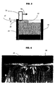
- the electrochemical bundle 30 once constituted is maintained in a centering tool 31, as shown in Figure 3, and the strips uncoated protruding side members 32 are bent with the aid of a tool 33, such as a hammer with a diameter of 15 to 20mm.
- the hammer 33 may advantageously consist of a plurality of small hammers, 5 to 8 mm in diameter, arranged in series.
- the hammer 33 moves up and down with a stroke of 3mm, then moves to the center of the beam in the direction indicated by the arrow 34 after shock rotation of it.
- the aforementioned heights H + and H- of the lateral bungs 15, 18 are such that the unfolded strips exceed from 6 to 7 mm from the ends of the separators 12.
- the ends of the separators are still spaced from the base of the folded strips 35 by at least 3 mm.
- Such a distance between the folded strips and the ends of the separators makes it possible to avoid any risk of burns of the separators during the subsequent step of welding a flat connection on the folded strips.
- the bending of the uncoated side bungs 32 of the strips 15 is obtained by repetitively compressing said strips in small successive passes of the hammer 33 on the same surface of approximately 20 to 50 mm 2 , the hammer 33 effecting a move up and down until you get a flat surface.
- the side strips of strips of the same polarity are thus folded into a kind of "accordion" to form a continuous plane base substantially perpendicular to the original direction of the strip.
- FIG. 4 shows the appearance of the electrode beam 30 after this operation on which we see the folded side strips 35 forming a flat and continuous base.
- the base 35 thus formed constitutes a metallic barrier allowing the welding of a flat connection to the laser.
- This base 35 receives a connection 36 which is laser welded, with contribution of material or transparency, so as to form two parallel beads 37 visible in FIG.
- This welding or laser is performed without drilling the plate of connection 36.
- material of the base 35 is melted by the laser beam which heats the sidebands folded strips. This melt spreads on the base 35 to constitute the weld.
- Such a welding process makes it possible to avoid any risk of welding projection inside the beam.
- the planar connection 36 may be a blade not covering the entire surface of the plane base 35 formed by the lateral bands of the folded strips.
- the gas emissions of the beam electrochemical can be directly discharged through the ends of the beam.
- the continuous plane base formed by the folded strips is not not gas tight.
- the flat connection 36 can also be pierced by a hole 38 in the axis of the electrode beam 30 to allow a good gas evolution through this orifice.
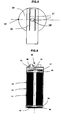
- FIG. 6 represents an electrochemical generator 60 of shape cylindrical hollow shaft 61 having an aluminum container 62 in which a beam 63 comprising an electrode has been introduced positive and a spiral negative electrode.
- the positive connection 64 plane is welded on the 65 strips not coated with the aluminum foil of the electrode negative, previously folded in the manner described previously.
- the positive connection 64 is on the other hand welded to the bottom 66 of the container 62 by laser welding or by electric welding, the two types of welding being waterproof.
- Negative connection 67 hovers, copper or nickel-plated copper, is welded in the same way on the strips 68 not coated with the copper strip of the positive electrode, previously folded in the manner previously described.
- the negative connection 67 is on the other hand soldered to an output terminal 69 of current by laser welding or ultrasonic welding.
- Terminal 69 of negative polarity is attached to a cover 70 which is welded or crimped onto the container 62.
- the terminal 69 is electrically isolated from the cover 70 by an insulating joint 71.
- the plane connection is welded according to at least one welding line tangent to the spiral axis of the electrodes, at the most close to this spiral axis to cover a maximum of strips metal.
- the plane connection is welded according to at least one weld line perpendicular to the plane of the electrodes.
Landscapes
- Chemical & Material Sciences (AREA)
- Chemical Kinetics & Catalysis (AREA)
- Electrochemistry (AREA)
- General Chemical & Material Sciences (AREA)
- Secondary Cells (AREA)
- Connection Of Batteries Or Terminals (AREA)
- Electric Double-Layer Capacitors Or The Like (AREA)
- Battery Electrode And Active Subsutance (AREA)
Applications Claiming Priority (2)
| Application Number | Priority Date | Filing Date | Title |
|---|---|---|---|
| FR0304528A FR2853764B1 (fr) | 2003-04-11 | 2003-04-11 | Raccordement electrique d'une connexion a un faisceau electrochimique |
| FR0304528 | 2003-04-11 |
Publications (3)
| Publication Number | Publication Date |
|---|---|
| EP1596449A2 true EP1596449A2 (de) | 2005-11-16 |
| EP1596449A3 EP1596449A3 (de) | 2007-04-11 |
| EP1596449B1 EP1596449B1 (de) | 2019-05-15 |
Family
ID=33041795
Family Applications (1)
| Application Number | Title | Priority Date | Filing Date |
|---|---|---|---|
| EP04290955.6A Expired - Lifetime EP1596449B1 (de) | 2003-04-11 | 2004-04-09 | Elektrische Verbindung zu einem Bündel von Elektroden-Anschlüssen |
Country Status (3)
| Country | Link |
|---|---|
| US (2) | US20050008933A1 (de) |
| EP (1) | EP1596449B1 (de) |
| FR (1) | FR2853764B1 (de) |
Cited By (10)
| Publication number | Priority date | Publication date | Assignee | Title |
|---|---|---|---|---|
| EP2093820A1 (de) | 2008-02-22 | 2009-08-26 | Saft Groupe S.A. | Elektrische Verbindung für Stromakkumulator |
| FR2974451A1 (fr) * | 2011-04-20 | 2012-10-26 | Accumulateurs Fixes | Connexion electrique pour accumulateur de courant |
| WO2015044820A1 (fr) | 2013-09-25 | 2015-04-02 | Commissariat A L'energie Atomique Et Aux Energies Alternatives | Procédé de réalisation d'un faisceau électrochimique d'un accumulateur au lithium |
| FR3030118A1 (fr) * | 2014-12-15 | 2016-06-17 | Saft Groupe Sa | Procede de connexion dans un accumulateur et accumulateur ainsi connecte |
| FR3037724A1 (fr) * | 2015-06-22 | 2016-12-23 | Commissariat Energie Atomique | Procede de realisation d'un faisceau electrochimique d'accumulateur au lithium avec pliage ou enroulement des extremites de feuillard sur elles-memes |
| WO2016207151A1 (fr) | 2015-06-22 | 2016-12-29 | Commissariat A L'energie Atomique Et Aux Energies Alternatives | Procede de realisation d'un faisceau electrochimique d'accumulateur metal-ion avec mousse metallique aux extremites de feuillards |
| WO2017216021A1 (fr) | 2016-06-15 | 2017-12-21 | Commissariat A L'energie Atomique Et Aux Energies Alternatives | Electrode pour faisceau electrochimique d'un accumulateur metal-ion ou d'un supercondensateur, procede de realisation du faisceau et de l'accumulateur associes |
| WO2018065473A1 (fr) | 2016-10-04 | 2018-04-12 | Saft | Accumulateur |
| FR3059159A1 (fr) * | 2016-11-23 | 2018-05-25 | Commissariat A L'energie Atomique Et Aux Energies Alternatives | Electrode pour faisceau electrochimique d'un accumulateur metal-ion a forte densite d'energie, accumulateur cylindrique ou prismatique associe |
| EP3649683B1 (de) | 2017-07-03 | 2021-10-27 | Monbat New Power GmbH | Verfahren und vorrichtung zur herstellung eines akkumulators und akkumulator |
Families Citing this family (18)
| Publication number | Priority date | Publication date | Assignee | Title |
|---|---|---|---|---|
| KR100627374B1 (ko) * | 2005-07-29 | 2006-09-22 | 삼성에스디아이 주식회사 | 이차 전지 |
| US20080259525A1 (en) * | 2005-11-09 | 2008-10-23 | Maxwell Technologies, Inc. | Energy storage apparatus and article of manufacture |
| KR20090012262A (ko) * | 2006-05-09 | 2009-02-02 | 발렌스 테크놀로지, 인코포레이티드 | 증가된 집전 효율을 갖는 2차 전기화학 전지 |
| JP5054419B2 (ja) * | 2006-07-06 | 2012-10-24 | エナックス株式会社 | シート状二次電池 |
| JP5550805B2 (ja) * | 2006-07-18 | 2014-07-16 | エルジー・ケム・リミテッド | 安定した電極リード−電極タブ結合部を有する電極組立体及びこれを備えた電気化学セル |
| FR2905525B1 (fr) | 2006-09-05 | 2008-10-31 | Accumulateurs Fixes | Dispositif de raccordement electrique pour borne de sortie d'un accumulateur de courant |
| US20080254354A1 (en) * | 2007-04-11 | 2008-10-16 | Saft | Connection system for an electrochemical cell |
| US8883345B2 (en) * | 2007-12-28 | 2014-11-11 | Encell Technology Llc | Prismatic battery |
| US8488301B2 (en) | 2011-02-28 | 2013-07-16 | Corning Incorporated | Ultracapacitor package design having slideably engagable bent tabs |
| CZ2016514A3 (cs) | 2014-01-28 | 2016-10-26 | A123 Systems Llc | Válcovité elektrochemické články a způsob jejich výroby |
| FR3019686B1 (fr) | 2014-04-08 | 2016-05-06 | Commissariat Energie Atomique | Accumulateur electrochimique au lithium avec borne en liaison directe avec le faisceau electrochimique, procedes de realisation associes. |
| GB2575981B (en) | 2018-07-30 | 2022-09-07 | Gp Batteries International Ltd | A battery |
| KR102836930B1 (ko) | 2018-11-05 | 2025-07-22 | 테슬라, 인크. | 탭리스 전극을 구비한 전지 |
| WO2022158857A2 (ko) | 2021-01-19 | 2022-07-28 | 주식회사 엘지에너지솔루션 | 전극 조립체, 배터리 및 이를 포함하는 배터리 팩 및 자동차 |
| US12132227B2 (en) | 2021-01-19 | 2024-10-29 | Lg Energy Solution, Ltd. | Battery, and battery pack and vehicle comprising the same |
| US12537229B2 (en) | 2021-02-19 | 2026-01-27 | Lg Energy Solution, Ltd. | Riveting structure of electrode terminal, and cylindrical battery cell, battery pack and vehicle including the same |
| JP7675188B2 (ja) | 2021-02-19 | 2025-05-12 | エルジー エナジー ソリューション リミテッド | 電極組立体、バッテリー、それを含むバッテリーパック及び自動車 |
| EP4618169A1 (de) | 2024-03-14 | 2025-09-17 | Wyon AG | Batterie mit einem elektrodenstapel sowie verfahren zur herstellung einer batterie mit einem elektrodenstapel |
Family Cites Families (4)
| Publication number | Priority date | Publication date | Assignee | Title |
|---|---|---|---|---|
| FR2094491A5 (de) * | 1970-06-23 | 1972-02-04 | Accumulateurs Fixes | |
| KR100417560B1 (ko) * | 1995-09-27 | 2004-04-28 | 소니 가부시끼 가이샤 | 젤리롤형고용량2차전지 |
| US5972532A (en) * | 1998-05-04 | 1999-10-26 | Saft America, Inc. | Current collection through the ends of a spirally wound electrochemical cell |
| JP4866496B2 (ja) * | 1999-04-08 | 2012-02-01 | パナソニック株式会社 | 二次電池の製造方法 |
-
2003
- 2003-04-11 FR FR0304528A patent/FR2853764B1/fr not_active Expired - Lifetime
-
2004
- 2004-04-09 EP EP04290955.6A patent/EP1596449B1/de not_active Expired - Lifetime
- 2004-04-09 US US10/820,788 patent/US20050008933A1/en not_active Abandoned
-
2008
- 2008-11-17 US US12/272,146 patent/US8007549B2/en not_active Expired - Lifetime
Cited By (16)
| Publication number | Priority date | Publication date | Assignee | Title |
|---|---|---|---|---|
| EP2093820A1 (de) | 2008-02-22 | 2009-08-26 | Saft Groupe S.A. | Elektrische Verbindung für Stromakkumulator |
| FR2974451A1 (fr) * | 2011-04-20 | 2012-10-26 | Accumulateurs Fixes | Connexion electrique pour accumulateur de courant |
| US9859546B2 (en) | 2013-09-25 | 2018-01-02 | Commissariat À L'energie Atomique Et Aux Energies Alernatives | Method for producing an electrochemical bundle of a lithium battery |
| WO2015044820A1 (fr) | 2013-09-25 | 2015-04-02 | Commissariat A L'energie Atomique Et Aux Energies Alternatives | Procédé de réalisation d'un faisceau électrochimique d'un accumulateur au lithium |
| US10062893B2 (en) | 2014-12-15 | 2018-08-28 | Saft Groupe Sa | Connection method in an accumulator and accumulator thus connected |
| EP3035411A1 (de) | 2014-12-15 | 2016-06-22 | Saft Groupe S.A. | Verbindungsverfahren in einem akkumulator, und so verbundener akkumulator |
| FR3030118A1 (fr) * | 2014-12-15 | 2016-06-17 | Saft Groupe Sa | Procede de connexion dans un accumulateur et accumulateur ainsi connecte |
| FR3037724A1 (fr) * | 2015-06-22 | 2016-12-23 | Commissariat Energie Atomique | Procede de realisation d'un faisceau electrochimique d'accumulateur au lithium avec pliage ou enroulement des extremites de feuillard sur elles-memes |
| WO2016207151A1 (fr) | 2015-06-22 | 2016-12-29 | Commissariat A L'energie Atomique Et Aux Energies Alternatives | Procede de realisation d'un faisceau electrochimique d'accumulateur metal-ion avec mousse metallique aux extremites de feuillards |
| WO2016207154A1 (fr) | 2015-06-22 | 2016-12-29 | Commissariat A L'energie Atomique Et Aux Energies Alternatives | Procede de realisation d'un faisceau electrochimique d'accumulateur metal-ion avec pliage ou enroulement des extremites de feuillard sur elles-memes |
| US10516150B2 (en) | 2015-06-22 | 2019-12-24 | Commissariat A L'energie Atomique Et Aux Energies Alternatives | Method for producing an electrochemical bundle for a metal-ion accumulator comprising folding or coiling the foil ends around themselves |
| WO2017216021A1 (fr) | 2016-06-15 | 2017-12-21 | Commissariat A L'energie Atomique Et Aux Energies Alternatives | Electrode pour faisceau electrochimique d'un accumulateur metal-ion ou d'un supercondensateur, procede de realisation du faisceau et de l'accumulateur associes |
| WO2018065473A1 (fr) | 2016-10-04 | 2018-04-12 | Saft | Accumulateur |
| FR3059159A1 (fr) * | 2016-11-23 | 2018-05-25 | Commissariat A L'energie Atomique Et Aux Energies Alternatives | Electrode pour faisceau electrochimique d'un accumulateur metal-ion a forte densite d'energie, accumulateur cylindrique ou prismatique associe |
| EP3649683B1 (de) | 2017-07-03 | 2021-10-27 | Monbat New Power GmbH | Verfahren und vorrichtung zur herstellung eines akkumulators und akkumulator |
| US11502380B2 (en) | 2017-07-03 | 2022-11-15 | Monbat New Power GmbH | Producing a rechargeable battery |
Also Published As
| Publication number | Publication date |
|---|---|
| US20090139082A1 (en) | 2009-06-04 |
| FR2853764B1 (fr) | 2009-06-05 |
| US8007549B2 (en) | 2011-08-30 |
| FR2853764A1 (fr) | 2004-10-15 |
| EP1596449A3 (de) | 2007-04-11 |
| US20050008933A1 (en) | 2005-01-13 |
| EP1596449B1 (de) | 2019-05-15 |
Similar Documents
| Publication | Publication Date | Title |
|---|---|---|
| EP1596449B1 (de) | Elektrische Verbindung zu einem Bündel von Elektroden-Anschlüssen | |
| EP0822605B1 (de) | Zylindrischer elektrochemischer Generator mit spiralförmig gewickelten Elektroden | |
| EP1898481B1 (de) | Vorrichtung mit elektrischem Anschluss für Ausgangsklemme eines Stromakkumulators | |
| JP5135368B2 (ja) | 角形電池およびその製造方法 | |
| EP3050138B1 (de) | Verfahren zur herstellung eines elektrochemischen bündels einer lithiumbatterie | |
| EP2093820B1 (de) | Elektrische Verbindung für Stromakkumulator | |
| EP3130020A1 (de) | Elektrochemischer lithium-ionen-akku mit direkt an die elektrodenanordnung angeschlossenem anschluss und zugehöriges herstellungsverfahren | |
| FR3125172A1 (fr) | Pièce de connexion pour élément électrochimique de format prismatique | |
| EP3035411B1 (de) | Verbindungsverfahren in einem akkumulator, und so verbundener akkumulator | |
| FR3037725A1 (fr) | Procede de realisation d'un faisceau electrochimique d'accumulateur au lithium avec mousse metallique aux extremites de feuillards | |
| FR2824667A1 (fr) | Connectique interne pour generateur electrochimique de forte puissance | |
| EP2812935B1 (de) | Verfahren zur herstellung einer anordnung für die speicherung elektrischer energie | |
| EP3316350B1 (de) | Elektrisches anschlussstück für akkumulator | |
| EP2239802B1 (de) | Batterie und Hestellungsverfahren | |
| FR3052917A1 (fr) | Electrode pour faisceau electrochimique d'un accumulateur metal-ion ou d'un supercondensateur, procede de realisation du faisceau et de l'accumulateur associes | |
| FR2771218A1 (fr) | Generateur electrochimique cylindrique au lithium a raccordement electrique ameliore du faisceau electrochimique spirale | |
| EP1026760B1 (de) | Spiralförmig gewickelter dreidimensionaler Elektroden-Support | |
| EP1465266B1 (de) | Elektrischer Anschlussverbinder | |
| FR2860103A1 (fr) | Procede de raccordement electrique d'une connexion sur une sortie de courant |
Legal Events
| Date | Code | Title | Description |
|---|---|---|---|
| PUAI | Public reference made under article 153(3) epc to a published international application that has entered the european phase |
Free format text: ORIGINAL CODE: 0009012 |
|
| AK | Designated contracting states |
Kind code of ref document: A2 Designated state(s): AT BE BG CH CY CZ DE DK EE ES FI FR GB GR HU IE IT LI LU MC NL PL PT RO SE SI SK TR |
|
| AX | Request for extension of the european patent |
Extension state: AL HR LT LV MK |
|
| PUAL | Search report despatched |
Free format text: ORIGINAL CODE: 0009013 |
|
| AK | Designated contracting states |
Kind code of ref document: A3 Designated state(s): AT BE BG CH CY CZ DE DK EE ES FI FR GB GR HU IE IT LI LU MC NL PL PT RO SE SI SK TR |
|
| AX | Request for extension of the european patent |
Extension state: AL HR LT LV MK |
|
| RAP1 | Party data changed (applicant data changed or rights of an application transferred) |
Owner name: SAFT, SA |
|
| 17P | Request for examination filed |
Effective date: 20071011 |
|
| AKX | Designation fees paid |
Designated state(s): DE FR GB |
|
| 17Q | First examination report despatched |
Effective date: 20071127 |
|
| GRAP | Despatch of communication of intention to grant a patent |
Free format text: ORIGINAL CODE: EPIDOSNIGR1 |
|
| INTG | Intention to grant announced |
Effective date: 20181116 |
|
| RIC1 | Information provided on ipc code assigned before grant |
Ipc: H01M 2/26 20060101AFI20050914BHEP |
|
| GRAJ | Information related to disapproval of communication of intention to grant by the applicant or resumption of examination proceedings by the epo deleted |
Free format text: ORIGINAL CODE: EPIDOSDIGR1 |
|
| GRAR | Information related to intention to grant a patent recorded |
Free format text: ORIGINAL CODE: EPIDOSNIGR71 |
|
| GRAS | Grant fee paid |
Free format text: ORIGINAL CODE: EPIDOSNIGR3 |
|
| GRAA | (expected) grant |
Free format text: ORIGINAL CODE: 0009210 |
|
| INTC | Intention to grant announced (deleted) | ||
| REG | Reference to a national code |
Ref country code: DE Ref legal event code: R081 Ref document number: 602004053969 Country of ref document: DE Owner name: SAFT, SA, FR Free format text: FORMER OWNER: SAFT, S.A., 93170 BAGNOLET, FR |
|
| INTG | Intention to grant announced |
Effective date: 20190322 |
|
| AK | Designated contracting states |
Kind code of ref document: B1 Designated state(s): DE FR GB |
|
| REG | Reference to a national code |
Ref country code: GB Ref legal event code: FG4D Free format text: NOT ENGLISH |
|
| REG | Reference to a national code |
Ref country code: DE Ref legal event code: R096 Ref document number: 602004053969 Country of ref document: DE |
|
| REG | Reference to a national code |
Ref country code: DE Ref legal event code: R097 Ref document number: 602004053969 Country of ref document: DE |
|
| PLBE | No opposition filed within time limit |
Free format text: ORIGINAL CODE: 0009261 |
|
| STAA | Information on the status of an ep patent application or granted ep patent |
Free format text: STATUS: NO OPPOSITION FILED WITHIN TIME LIMIT |
|
| 26N | No opposition filed |
Effective date: 20200218 |
|
| REG | Reference to a national code |
Ref country code: DE Ref legal event code: R079 Ref document number: 602004053969 Country of ref document: DE Free format text: PREVIOUS MAIN CLASS: H01M0002260000 Ipc: H01M0050531000 |
|
| PGFP | Annual fee paid to national office [announced via postgrant information from national office to epo] |
Ref country code: FR Payment date: 20210412 Year of fee payment: 18 |
|
| PGFP | Annual fee paid to national office [announced via postgrant information from national office to epo] |
Ref country code: GB Payment date: 20210430 Year of fee payment: 18 |
|
| PGFP | Annual fee paid to national office [announced via postgrant information from national office to epo] |
Ref country code: DE Payment date: 20220429 Year of fee payment: 19 |
|
| GBPC | Gb: european patent ceased through non-payment of renewal fee |
Effective date: 20220409 |
|
| PG25 | Lapsed in a contracting state [announced via postgrant information from national office to epo] |
Ref country code: GB Free format text: LAPSE BECAUSE OF NON-PAYMENT OF DUE FEES Effective date: 20220409 Ref country code: FR Free format text: LAPSE BECAUSE OF NON-PAYMENT OF DUE FEES Effective date: 20220430 |
|
| REG | Reference to a national code |
Ref country code: DE Ref legal event code: R119 Ref document number: 602004053969 Country of ref document: DE |
|
| PG25 | Lapsed in a contracting state [announced via postgrant information from national office to epo] |
Ref country code: DE Free format text: LAPSE BECAUSE OF NON-PAYMENT OF DUE FEES Effective date: 20231103 |