EP1596400A2 - Methods of repairing leaking elongate hollow members in boiling water reactors - Google Patents
Methods of repairing leaking elongate hollow members in boiling water reactors Download PDFInfo
- Publication number
- EP1596400A2 EP1596400A2 EP05252908A EP05252908A EP1596400A2 EP 1596400 A2 EP1596400 A2 EP 1596400A2 EP 05252908 A EP05252908 A EP 05252908A EP 05252908 A EP05252908 A EP 05252908A EP 1596400 A2 EP1596400 A2 EP 1596400A2
- Authority
- EP
- European Patent Office
- Prior art keywords
- lower portion
- weld
- stub tube
- bottom head
- pressure vessel
- Prior art date
- Legal status (The legal status is an assumption and is not a legal conclusion. Google has not performed a legal analysis and makes no representation as to the accuracy of the status listed.)
- Ceased
Links
Images


Classifications
-
- G—PHYSICS
- G21—NUCLEAR PHYSICS; NUCLEAR ENGINEERING
- G21C—NUCLEAR REACTORS
- G21C13/00—Pressure vessels; Containment vessels; Containment in general
- G21C13/02—Details
- G21C13/032—Joints between tubes and vessel walls, e.g. taking into account thermal stresses
- G21C13/036—Joints between tubes and vessel walls, e.g. taking into account thermal stresses the tube passing through the vessel wall, i.e. continuing on both sides of the wall
-
- F—MECHANICAL ENGINEERING; LIGHTING; HEATING; WEAPONS; BLASTING
- F16—ENGINEERING ELEMENTS AND UNITS; GENERAL MEASURES FOR PRODUCING AND MAINTAINING EFFECTIVE FUNCTIONING OF MACHINES OR INSTALLATIONS; THERMAL INSULATION IN GENERAL
- F16L—PIPES; JOINTS OR FITTINGS FOR PIPES; SUPPORTS FOR PIPES, CABLES OR PROTECTIVE TUBING; MEANS FOR THERMAL INSULATION IN GENERAL
- F16L5/00—Devices for use where pipes, cables or protective tubing pass through walls or partitions
- F16L5/02—Sealing
- F16L5/022—Sealing by welding
-
- G—PHYSICS
- G21—NUCLEAR PHYSICS; NUCLEAR ENGINEERING
- G21C—NUCLEAR REACTORS
- G21C17/00—Monitoring; Testing ; Maintaining
- G21C17/017—Inspection or maintenance of pipe-lines or tubes in nuclear installations
-
- Y—GENERAL TAGGING OF NEW TECHNOLOGICAL DEVELOPMENTS; GENERAL TAGGING OF CROSS-SECTIONAL TECHNOLOGIES SPANNING OVER SEVERAL SECTIONS OF THE IPC; TECHNICAL SUBJECTS COVERED BY FORMER USPC CROSS-REFERENCE ART COLLECTIONS [XRACs] AND DIGESTS
- Y02—TECHNOLOGIES OR APPLICATIONS FOR MITIGATION OR ADAPTATION AGAINST CLIMATE CHANGE
- Y02E—REDUCTION OF GREENHOUSE GAS [GHG] EMISSIONS, RELATED TO ENERGY GENERATION, TRANSMISSION OR DISTRIBUTION
- Y02E30/00—Energy generation of nuclear origin
- Y02E30/30—Nuclear fission reactors
Definitions
- This present invention relates, in general, to repairing or sealing leaking elongate hollow members such as control rod drive housings and in-core monitor housings in a reactor pressure vessel of a nuclear reactor such as a boiling water reactor.
- Boiling water nuclear reactors typically may include a reactor core located within a reactor pressure vessel (RPV).
- RPV reactor pressure vessel
- a known RPV may include a substantially cylindrical shell.
- the shell for example, can be about twenty feet in diameter and about seven inches thick.
- the cylindrical shell may be closed at its top end by a removable top head.
- the top head may be removable so that components, such a fuel bundles, located in the RPV can be accessed.
- the RPV cylindrical shell may be closed at its bottom end by a dome shaped bottom head assembly welded to the shell.
- a plurality of openings may be formed in the bottom head dome so that components, such as control rod drive assemblies, can extend within the RPV.
- a substantially cylindrical stub tube having a bore extending there through may be welded to the bottom head dome so that the tube bore aligns with an opening in the bottom head dome.
- the cylindrical stub tube may typically be fabricated from a corrosion resistant material such as stainless steel or Ni--Cr--Fe.
- the control rod drive housing e.g., a tube
- the housing may extend into the RPV.
- the control rod drive (CRD) housing may be welded to the stub tube to maintain the housing in a desired position.
- the stub tube thus may serve as a transition piece between the bottom head dome, which typically may be fabricated from low alloy steel , and the CRD housing, which typically may be fabricated from stainless steel such as 304 stainless steel with a high carbon content.
- Inter-granular stress corrosion cracking is a known phenomenon occurring adjacent to stub tube welds connecting the bottom head dome to the stub tube and connecting the stub tube to the CRD housing.
- the stub tube welds may be subject to a variety of stresses associated with, for example, differences in thermal expansion, the operating pressure needed for the containment of the reactor cooling water, and other sources such as residual stresses from welding, cold working and other inhomogeneous metal treatments. Such stresses may, at times, cause cracks adjacent the stub tube welds.
- Type 304 stainless steel stub tubes in some plants have become furnace sensitized as a result of vessel post weld heat treatment. This has left the stub tube in an inter-granular stress corrosion cracking (IGSCC) susceptible state, and has led to leaking cracks. Cracking has been observed in the heat affected zone of the stub tube at the CRD housing attachment weld of this susceptible material. This results in a reactor coolant leakage path to the under-vessel area. Restoration of the defective area is virtually impossible due to the location of the stub tubes and the existing material condition.
- IGSCC inter-granular stress corrosion cracking
- One known method of repairing or re-sealing CRD housings within the bottom head dome includes completely replacing the stub tube and CRD housing. This method, however, is time consuming, tedious, and expensive. Particularly, the housing and associated stub tube are partially cut-off and removed from the bottom head dome, and the material remaining in the bottom head assembly is inspected to ensure that such material can be welded without damaging the bottom head. A weld build-up may then be formed over the remaining material and machined so that a new stub tube can be welded to the weld build-up. Several weeks can be required to perform the replacement process of just one penetration tube. Moreover, much of the replacement work must be performed within the RPV, which requires completely unloading the RPV and is undesirable.
- Another known method of repairing or re-sealing a CRD housing within the bottom head dome includes welding a sleeve to the CRD housing and the stub. This method, however, only addresses stress corrosion cracks adjacent the interface between the stub tube and the CRD housing. Moreover, installing the sleeve must be performed entirely within the RPV which, as explained above, is undesirable.
- Another known method of repairing or re-sealing a CRD housing within the bottom head dome includes rolling the CRD housing into the bottom head dome. While this method may be quicker than replacing the stub tube and CRD housing, rolling the CRD housing into the bottom head dome does not create as tight a seal as a weld between the CRD housing and the dome. Moreover, the rolled CRD housing may become separated from the bottom head dome after continued RPV operation, and must then be re-rolled. Re-rolling a CRD housing, however, often is neither desirable nor practical.
- Another known method of repairing or re-sealing a CRD housing within the bottom head dome includes removing and replacing a lower portion of the CRD housing within the bottom head dome. Particularly, a lower portion of the CRD housing is cut-off and removed so that an upper portion of the CRD housing remains inserted in an opening in the bottom head dome and welded to the stub tube. The bottom head dome is then cleaned, and the lower end of the remaining CRD housing upper portion is machined so that a replacement bottom portion of CRD housing can be welded to the remaining upper portion.
- the replacement bottom portion of CRD housing is similarly machined so that it can be welded to the remaining upper portion.
- the replacement bottom portion of CRD housing is then inserted into the bottom head dome opening and positioned beneath the remaining upper portion.
- the replacement bottom portion and the remaining upper portion of CRD housing are temper bead welded to each other and to the bottom head dome.
- Temper bead welding the remaining upper portion to the replacement lower portion and the bottom head dome may have the undesirable effect of causing high stresses because of thermal growth mismatch between the CRD housing and the bottom head dome, which are fabricated from different materials. Such temper bead welding also has the undesirable potential effect of trapping water within a leakage path and in contact with the weld between the remaining upper portion and the bottom head dome.
- An exemplary embodiment of the present invention is directed to a method for sealing a hollow, elongate member within a reactor pressure vessel of a nuclear reactor.
- a section of the elongate member may be removed to separate the elongate member into an upper portion and a lower portion with an opening there between.
- the lower portion may be attached to a surface of the reactor pressure vessel in-situ, so as to seal off a potential leakage path through the elongate member.
- Another exemplary embodiment of the present invention is directed to an in-situ repair method to seal a hollow, elongate hollow member within a reactor pressure vessel of a nuclear reactor.
- the elongate member may be cut at a given location to remove a section of the elongate member so as to form an upper portion and a lower portion with an opening between the upper and lower portions.
- a weld may be applied to attach the lower portion to the reactor pressure vessel so as to seal off potential leakage paths between the upper portion and lower portion.
- the reactor pressure vessel includes a bottom head dome, a stub tube, and the elongate hollow member.
- the bottom head dome may have at least one opening therein
- the stub tube may have first and second ends with a bore there between
- the elongate member may extend through the stub tube bore and may be secured to the stub tube adjacent the stub tube first end with an upper stub tube attachment weld.
- a section of the elongate member may be cut out at a location below the upper stub tube weld to separate the elongate member into an upper portion and a lower portion.
- the lower portion may be attached to a different location at the bottom head dome opening than where the elongate member was cut with a weld.
- the weld may be formed on an interior surface of the bottom head dome opening at an upper end of the lower portion, with application of the weld forming a heat affected zone.
- a corrosion resistant material may be applied on the heat-affected zone.
- control rod drive housing within a reactor pressure vessel of a nuclear reactor.
- the control rod drive housing is inserted within a stub tube through a bottom head dome of the reactor pressure vessel, and at least part of the control rod drive housing may be fixedly secured to the bottom head dome via the stub tube.
- the control road drive housing may include an upper portion and a lower portion. The lower portion may be formed by cutting the control rod drive housing to remove a section of the control rod drive housing below the stub tube. The lower portion may be subjected to an in-situ repair to seal potential leakage paths in the control rod drive housing.
- Another exemplary embodiment of the present invention is directed to an in-core monitor housing within a reactor pressure vessel of a nuclear reactor.
- the in-core monitor housing is inserted within a stub tube weld buildup through a bottom head dome of the reactor pressure vessel, and at least part of the in-core monitor housing may be fixedly secured to the bottom head dome via the stub tube weld buildup.
- the in-core monitor housing may include an upper portion and a lower portion.
- the lower portion may be formed by cutting the in-core monitor housing to remove a section of the in-core monitor housing below the stub tube weld buildup.
- the lower portion may be subjected to an in-situ repair to seal potential leakage paths in the in-core monitor housing.
- Fig. 1 is a schematic illustration of a reactor pressure vessel (RPV) 10.
- RPV 10 includes a top head 12, four substantially cylindrical shell courses 14, 16, 18 and 20, and a bottom head assembly 22.
- Top head 12 includes a head flange 24.
- First shell course 14 includes a vessel flange (not shown).
- Top head 12 is bolted to first shell course 14 by bolts 26 which extend through head flange 24.
- Top head 12 also includes a head spray and vent nozzle 28 and lifting flanges 30 used when lifting top head 12 from first shell course 14.
- First shell course 14 includes main steam nozzles 32 through which steam flows out of the RPV 10. Stabilizer brackets 34 also are formed on first shell course 14. Second shell course 16 has a number of nozzles 36, 38 and 40 formed therein. Fourth shell course 20 includes a support skirt 42 welded thereto. Support skirt 42 is utilized to support RPV 10 within the reactor housing (not shown).
- Bottom head assembly 22 includes a bottom head dome 44 having a plurality of stub tubes 46 welded thereto.
- Stub tubes 46 are substantially cylindrical and each stub tube 46 has a bore (not shown in Fig. 1) extending there through. The bore of each stub tube 46 is aligned with an opening (not shown in Fig. 1) in bottom head dome 44.
- Components such as control rod drives, in-core instruments, pressure instrument nozzles, and drain nozzles extend through such bottom head dome openings and stub tube bores and penetrate into RPV 10.
- Fig. 1 is provided primarily for illustrative purposes to show a typical bottom head assembly 22.
- the present invention as described below in the exemplary embodiments, can be used in many RPV configurations other than RPV 10.
- Fig. 2 is a partial cross-sectional view of a control rod drive housing, a stub tube, and a bottom head of a reactor pressure vessel to illustrate a potential leakage path to be sealed and/or repaired, in accordance with an exemplary embodiment of the present invention.
- bottom head dome 44 may be fabricated from low alloy steel, may have a thickness TBH and a stainless steel cladding 48 and may include a substantially cylindrical opening 52 therein defined by a sidewall 54, for receiving a control rod drive (CRD) housing 50 and a stub tube 46.
- CRD housing 50 may be fabricated of compatible corrosion resistant materials such as Type 304 stainless steel of Ni-Cr-Fe, and stub tube 46 of Type 304 stainless steel that is furnace sensitized and overlaid, for example.
- Stub tube 46 may include a first end 56 and a second end 58, with a stub tube bore 60 extending between first and second ends 56 and 58.
- Stub tube 46 may be positioned concentric to bottom head dome opening 52 so that the stub tube bore 60 may be substantially aligned with bottom head dome opening 52, for example.
- Stub tube 46 may be secured to bottom head dome 44 with a lower stub tube attachment weld 62.
- An outer surface 64 of stub tube sidewall 66 proximate second end 58 may be welded to bottom head dome 44 with lower stub tube attachment weld 62.
- CRD housing 50 may include a first end (not shown), a second end (not shown), and a bore 68 extending between the first and second ends.
- Control rod drive housing 50 may have a substantially hollow cylindrical geometric shape including a sidewall 70 having an outer surface 72 and an inner surface 74 which defines bore 68.
- CRD housing 50 may be positioned so that it extends through bottom head dome opening 52 and stub tube bore 60.
- An upper portion 76 of CRD housing 50 may be secured to stub tube 46 with an upper stub tube attachment weld 78 adjacent stub tube first end 56 so that CRD housing 50 may be substantially concentrically and fixedly secured within stub tube 46.
- the positioning and welding of CRD housing 50 within stub tube 46 and bottom head dome 44 is well known.
- annulus leakage path 82 may be formed between an inner surface 84 of stub tube sidewall 66 and outer surface 72 of CRD housing 50, as shown in FIG. 2.
- annulus leakage path 85 may be formed between outer surface 72 of CRD housing 50 and sidewall 54 of bottom head dome opening 52.
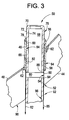
- Fig. 3 is a modification of the partial cross-sectional view of FIG. 2 to describe an intermediate step of removing a section of the CRD housing, in accordance with an exemplary embodiment of the present invention.
- the CRD housing 50 may require repair.
- the repair work can be performed from the under-vessel with a water tight (temporary) seal placed over the stub tube from inside the vessel, for example.
- the reactor vessel remains flooded to provide radiation shielding and reduce overall outage time.
- CRD housing 50 may be cut at a location 86 below upper stub tube attachment weld 78.
- CRD housing 50 may be cut at location 86 at a desired point below stub tube second end 58 to remove a section of CRD housing 50, so as to separate upper portion 76 of CRD housing 50 from a lower portion 92 of CRD housing 50, forming an opening 80, as shown in FIG. 3.
- the lower portion 92 is not removed, but remains in place for an in-situ repair.
- the width (or height) of the sectional cut out may be based on providing sufficient clearance for a weld help of a welding apparatus to apply a weld to attach lower portion 92 to RPV 10, as will be described in further detail below.
- the opening 80 may be of a size that is about 2-3 times the weld thickness of an eventual weld applied by the weld head, so as to provide sufficient room for the weld head.
- the bottom head dome opening 52 may be cleaned.
- a grinder (not shown) may be extended into bottom head dome opening 52, through bore 68 into lower portion 92 within opening 80, and utilized to grind sidewall 54 of bottom head dome opening 52 between a lower end 88 of upper portion 76 and a bottom end 90 of bottom head dome 44 to form a weld passage (e.g., area over which a weld may be applied) between lower end 88 and bottom end 90.
- bottom head dome opening 52 may be cleaned with a flapper wheel or by honing. Methods for cleaning bottom head dome opening 52 are known and are not described herein for reasons of brevity.
- Fig. 4 is a modification of the partial cross-sectional view of FIG. 3 to describe an intermediate step of applying a temper bead weld to attach a lower portion of the CRD housing to a surface of the reactor pressure vessel, in accordance with an exemplary embodiment of the present invention.
- the existing lower portion 92 that remains in place for the repair may then be attached to a surface of the RPV 10, such as at the sidewall 54 of the bottom head dome opening 52, so that it may be substantially aligned with and adjacent to upper portion 76.
- Existing lower portion 92 may be a substantially hollow member having a substantially cylindrical geometric shape.
- Existing lower portion 92 includes an upper end 94, a lower end (not shown), and through bore 96 extending between the upper end 94 and the lower end.
- the upper end 94 of existing lower portion 92 may include a weld prep 98 for welding upper end 94 to sidewall 54 of bottom head dome opening 52.
- the upper end 94 of existing lower portion 92 may be cleaned in accordance with known methods so that upper end 94 has a substantially frusto-conical geometric shape. This may provide a clean oxide-free surface to form weld prep 98.
- a grinder may be used to grind upper end 94.
- upper end 94 may be cleaned with a flapper wheel or by honing.
- Existing lower portion 92 may be attached, in-situ, to sidewall 54 bottom head dome opening 52 so that upper end 94 is proximate lower end 88 of remaining upper portion 76, and so that control rod housing bore 68 remains substantially aligned with through bore 96. As shown in Fig. 4, upper end 94 of existing lower portion 92 may be spaced from lower end 88 of remaining upper portion 76, with opening 80 there between. The pressure seal weld has thus been moved from the upper stub tube attachment weld 78 to the weld prep 98 at opening 80.
- upper stub tube attachment weld 78 is no longer a pressure weld and the annulus leakage path 82 between the inner surface 84 of stub tube sidewall 66 and the outer surface 72 of CRD housing 50 (or alternatively annulus leakage path 85 between outer surface 72 and sidewall 54) are no longer leak paths since the pressure in these paths equals the pressure in bore 68.
- the lower portion 92 within bottom head dome opening 52 may be attached to sidewall 54 of bottom head dome opening 52 without also being secured to lower end 88 of remaining portion 76.
- the existing lower portion 92 may be attached at a point or location that is different from the location where it was initially cut, e.g., lower than where lower portion 92 was cut initially at location 86 below the stub tube second end 58, to separate upper portion 76 of CRD housing 50 from lower portion 92.
- Upper end 94 of lower portion 92 may be bead welded to provide a weld 97 at upper end 94 (partially filling opening 80, as shown in FIG. 4), using known welding methods such as temper bead welding techniques, for example, at sidewall 54 of bottom head dome opening 52.
- the weld 97 may be provided at a location that is below potential differential leakage paths in the CRD 50.
- this location may be at a point that is lower than annulus leakage path 82 between inner surface 84 of stub tube sidewall 66 and outer surface 72 of CRD 50; and/or below annulus leakage path 85 formed between outer surface 72 of CRD housing 50 and sidewall 54 of bottom head dome opening 52, as shown in Fig. 2.
- an automatic welding machine may be inserted in through bore 96 so that a welding head is substantially adjacent to weld prep 98.
- the automatic welding machine then may be used to apply a temper bead weld 97 to sidewall 54 of bottom head dome opening 52, as is known.
- a UT machine for example, may then be inserted in through bore 96 to ascertain the quality of the bead weld.
- Fig. 5 is a modification of the partial cross-sectional view of FIG. 4 to describe a step of applying an overlay corrosion resistant material at a heat affected zone on the lower portion of the control rod drive housing, in accordance with an exemplary embodiment of the present invention.
- the welding of existing lower portion 92 in-situ to attach it to the bottom head dome 44 at bottom head dome opening 52 may introduce a new heat affected zone 99 in the high carbon stainless steel at weld 97, which ordinarily may be susceptible to IGSCC.
- the heat affected zone 99 may be covered with a corrosion resistant material, which may be a cladding 89 that is applied over the heat affected zone 99 of weld 97.
- the application of corrosion resistant cladding 89 may thus reduce the probability of introducing a new potential failure mechanism, for example.
- the CRD housing 50 may be sealed at the top, near upper section 76 to provide a dry environment inside.
- the outside of the CRD housing 50 remains wet.
- an apparatus or tool such as a weld head may be inserted from a bottom end (not shown) of the CRD housing 50.
- the weld head may be as much as 13 feet in length or longer.
- the weld head may include a gas-tungsten arc welding head near the top of the weld head.
- the gas-tungsten arc welding head may include a torch and a weld wire feeder, and rotates and moves up or down, in a slow manner in order to apply a thin cladding layer.
- the cladding 89 is corrosion resistant due to its fine ferrite structure.
- the cladding material typically may consist of a metal alloy, such as Alloy 82, Type 308L stainless steel or Type 316L stainless steel; however, the cladding applicable to the exemplary embodiments of the present invention is not limited to these alloys.
- cladding 89 may be alloyed with a noble metal to provide additional mitigation to stress corrosion cracking.
- a welding apparatus and technique used to apply the cladding with alloyed noble metal is described in commonly assigned U.S. Patent Application Serial No. 09/416,943 to OFFER et al., entitled APPARATUS AND METHOD FOR CORROSION RESISTANT CLADDING, the contents of which are hereby incorporated by reference in their entirety. Briefly described, the welding technique joins the cladding 89 to the heat affected zone 99, which is a region susceptible to stress corrosion cracking.
- the cladding 89 may be applied under conditions of low heat input to achieve reduced or no thermal sensitization at the edges of the newly clad region.
- the welding apparatus may apply a cladding that includes a filler material comprised of nickel-base alloys or iron-base stainless steels such as the aforementioned Inconel 82, Stainless 308L or Stainless 316L, for example, which may be alloyed with a low concentration of a noble metal element (e.g., palladium, platinum, rhodium, or combinations thereof) to act as a catalyst for improved recombination rates of oxygen with hydrogen, at reduced hydrogen addition levels.
- the concentration of noble metal in the filler material may be in the region of about 1% by weight or less, such as within a range of about 0.25 to 0.75% by weight after dilution by base metal. Recombination of the oxygen and hydrogen peroxide with hydrogen may reduce the effective electrochemical potential, in order to reduce the susceptibility to IGSCC.
- the welding apparatus may remotely apply the cladding 89 at a significant distance from the end of the apparatus, as noted above.
- the welding apparatus may have the ability to provide a substantially stable arc voltage (and corresponding arc length control) even though the torch is positioned far from weld head drive mechanisms.
- the welding apparatus may include a rotating wire feeder which produces a wire pool substantially far downstream of the distal end of the wire feeder. Weldability at substantially low, yet stable, wire feed rates (e.g., approximately 60-80 cm/min) may therefore be improved, enabling substantially thin cladding to be reliably deposited, with a cladding thickness in a range of about 0.3-0.6 mm, and more preferably between about 0.36 to 0.45 mm thick.
- the welding torch of the welding apparatus may use a sufficiently low heat input (in a range of about 0.6-1.0 kJ/cm, for example) so that a required through-wall temperature gradient for far-wall stress improvement may be obtained, even without liquid cooling on a far wall.
- the reduced heat input to apply the cladding 89 may be produced in part by a travel speed (torch speed) in excess of about 10 inches per minute, for example 15 to 40 inches per minute, more usually about 15-30 inches per minute, so that the time in the sensitizing temperature range during cooling of the applied cladding 89 is insufficient to allow carbides to precipitate on the grain boundaries.
- travel speed in excess of about 10 inches per minute, for example 15 to 40 inches per minute, more usually about 15-30 inches per minute
- Sensitization control may be effected utilizing dual controls on welding parameters: (1) heat input (controlled as a function of the heat input per unit length of bead), and (2) heat affected zone cooling rate (controlled as a function of the welding linear speed in the forward direction).
- Undesirable cross-bead arc oscillation may be avoided, since it is counterproductive with respect to maintaining both the required low heat input and high travel speed.
- electric-arc based cladding processes may be applied to the heat affected zone 99 even with very low resistance to thermal sensitization, and without high risk of sensitization.
- the method of permanently repairing or sealing an elongate hollow member such as CRD housing/stub tube may also be applied to in-core monitor housings (ICMH).
- ICMH is smaller diameter vessel penetration than the CRD housing/stub tube located in a reactor pressure vessel bottom head region. There are typically between about 29-70 ICMH's, depending upon the size of the reactor pressure vessel.
- the method may be applied to ICMHs that do not contain a stub tube but include a stub tube weld buildup that approximates the functions and structure of a stub tube.
- the welding apparatus described above for applying cladding 89 over the heat affected zone 99 in the exemplary embodiments directed to the CRD housing 50 may also be used to apply a weld and cladding over desired surfaces of the ICMH's, as to be described further below.
- the weld may be a metal that may be alloyed with a noble metal to reduce susceptibility to IGSCC, for example.
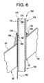
- Fig. 6 is a partial cross-sectional view of an in-core monitor housing, a stub tube weld buildup, and a bottom head of a reactor pressure vessel to illustrate a potential leakage path to be sealed and/or repaired, in accordance with another exemplary embodiment of the present invention.
- ICMH 150 may be fabricated of compatible corrosion resistant materials such as Type 304 stainless steel of Ni-Cr-Fe, and may be secured through a bottom head dome opening 52 of bottom head dome 44 with a stub tube weld buildup 146 that is attached to vessel cladding 48 (or directly to the bottom head dome 44) at one end and to a J-weld 178 at another end.
- Stub tube weld buildup 146 may be of a corrosion resistant material such as Type 304 stainless steel that is furnace sensitized and overlaid, for example.
- ICMH 150 may include a first end (not shown), a second end (not shown), and a bore 168 extending between the first and second ends.
- ICMH 150 may have a substantially hollow cylindrical geometric shape including a sidewall 170 having an outer surface 172 and an inner surface 174 which defines bore 168.
- ICMH 150 may be positioned so that it extends through bottom head dome opening 52.
- An upper portion 176 of ICMH 150 may be secured to stub tube weld buildup 146 with a J-weld 178, so that ICMH 150 may be substantially concentrically and fixedly secured within stub tube weld buildup 146.
- J-weld 178 stress corrosion cracks sometimes may occur adjacent J-weld 178.
- the process of applying J-weld 178 may create a heat affected zone (no shown) that is susceptible to IGSCC, and which could cause a crack above or below J-weld 178.
- an annulus leakage path 182 may be formed between an inner surface 184 of stub tube buildup 146 and outer surface 172 of ICMH 150, as shown in FIG. 6.
- only one leakage path 182 is shown, it being understood that a leakage path may be formed between outer surface 172 of ICMH 150 and sidewall 54 of bottom head dome opening 52.
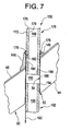
- Fig. 7 is a modification of the partial cross-sectional view of FIG. 6 to describe an intermediate step of removing a section of the in-core monitor housing, in accordance with an exemplary embodiment of the present invention.
- the ICMH 150 may require repair similar to as described above with respect to CRD housing 50.
- the repair work can be performed from the under-vessel with a water tight (temporary) seal, and the reactor vessel remains flooded to provide radiation shielding and reduce overall outage time.
- ICMH 150 may be cut at a location 186 below J-weld 178 and/or stub tube weld buildup 146, as shown in FIG. 7, and a section may be removed from ICMH 150 so as to separate upper portion 176 of ICMH 150 from a lower portion 192 of ICMH 150, forming an opening 180.
- the ICMH 150 may be cut below the lowest elevation of weld buildup 146, so that the region encompassing opening 180 is adjacent the sidewall 54 of the bottom head dome opening 52, as shown in FIG. 7.
- the lower portion 192 is not removed, but remains in place for an in-situ repair. After cutting the lower portion 192, the bottom head dome opening 52 may be cleaned as described above and thus not repeated herein for reasons of brevity.
- Fig. 8 is a modification of the partial cross-sectional view of FIG. 7 to describe an intermediate step of applying a temper bead weld to attach a lower portion of the in-core monitor housing to a surface of the reactor pressure vessel, in accordance with an exemplary embodiment of the present invention.
- the existing lower portion 192 that remains in place for the repair may then be attached to a surface of the RPV 10, such as at the sidewall 54 of the bottom head dome opening 52, so that it may be substantially aligned with and adjacent to upper portion 176.
- Existing lower portion 192 may be a substantially hollow member having a substantially cylindrical geometric shape.
- Existing lower portion 192 includes an upper end 194, a lower end (not shown), and a through bore 196 extending between the upper end 194 and the lower end.
- the upper end 194 of existing lower portion 192 may include a weld prep 198 for welding upper end 194 to sidewall 54 of bottom head dome opening 52.
- the upper end 194 of existing lower portion 192 may be cleaned in accordance with known methods, such as described above, so that upper end 194 has a substantially frusto-conical geometric shape. This may provide a clean oxide-free surface to form weld prep 198.
- Existing lower portion 192 may be attached, in-situ, to sidewall 54 of bottom head dome opening 52 so that upper end 194 is proximate lower end 188 of remaining upper portion 176, and so that ICMH bore 168 remains substantially aligned with through bore 196. As shown in Fig. 8, upper end 194 of existing lower portion 192 may be spaced from lower end 188 of remaining upper portion 176, with opening 180 there between.
- J-weld 178 is no longer a pressure weld and the annulus leakage path 182 between inner surface 184 of stub tube buildup 146 and the outer surface 172 of ICMH 150 (or alternatively annulus leakage path 185 between outer surface 172 and sidewall 54) are no longer leak paths since the pressure in these paths equals the pressure in bore 168.
- the lower portion 192 within bottom head dome opening 52 may be attached to sidewall 54 of bottom head dome opening 52 without also being secured to lower end 188 of remaining upper portion 176.
- the existing lower portion 192 may be attached at a point or location that is different from the location where it was initially cut, e.g., lower than where lower portion 192 was cut at location 186 to separate upper portion 176 of ICMH 150 from lower portion 192.
- Upper end 194 of lower portion 192 may be bead welded to provide a weld 197, using known welding methods such as described above, at sidewall 54 of bottom head dome opening 52.
- the weld 197 may be provided at a location that is below potential differential leakage paths in the ICMH 150, such as at a point lower than annulus leakage path 182 between inner surface 184 of stub tube buildup 146 and outer surface 172 of ICMH 50; and/or below a leakage path that is formed between outer surface 172 and sidewall 54 of bottom head dome opening 52.
- the weld may be formed by techniques as described above, thus a detailed explanation is omitted here for reasons of brevity.
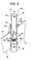
- Fig. 9 is a modification of the partial cross-sectional view of FIG. 8 to describe a step of applying an overlay corrosion resistant material at a heat affected zone on the lower portion of the in-core monitor housing, in accordance with an exemplary embodiment of the present invention.
- the welding of existing lower portion 192 in-situ to attach it to the bottom head dome 44 at bottom head dome opening 52 may introduce the aforementioned heat affected zone 199 in the high carbon stainless steel at weld 197, which ordinarily may be susceptible to IGSCC.
- the heat affected zone 199 may be covered with a corrosion resistant material, which may be a cladding 189 that is applied over the heat affected zone 199 of weld 197.
- the application of corrosion resistant cladding 189 may thus reduce the probability of introducing a new potential failure mechanism, for example.
- the cladding may be applied as described above with respect to FIG. 5, thus a detailed explanation is omitted here for reasons of brevity.
- the cladding 189 is corrosion resistant due to its fine ferrite structure, and may consist of a metal alloy, such as Alloy 82, Type 308L stainless steel or Type 316L stainless steel; however, the cladding applicable to this exemplary embodiment is not limited to these alloys. Further as describe above, cladding 189 may be alloyed with a noble metal to provide additional mitigation to stress corrosion cracking, such as is described in the commonly assigned application '943 to OFFER et al.
- FIGS. 6-9 may also be applicable to ICMHs which may have potential through wall cracks in what is known as a 'low-profile stub tube weld buildup' due to IGSCC, which may cause leakage paths between an inner surface of the low-profile stub tube weld buildup and an outer surface of the ICMH, down through the bottom head dome opening 52, similar to as shown in FIG. 6.
- a low-profile stub tube weld buildup has a substantially small weld height as compared to the weld buildup 178 shown in FIG. 6, for example.
- the above-described methods in accordance with the exemplary embodiments may facilitate permanent repairs of stress corrosion cracks adjacent the upper stub tube weld and the lower stub tube weld of a CRD housing, and/or adjacent a J-weld and stub tube weld buildup of an ICMH, more quickly and more easily than known methods.
- the repair may be performed in-situ, without having to remove a substantial portion of an elongate member such as CRD housing 50 or ICMH 150 and associated hydraulic lines.
- such repairs may be substantially completed in-situ from below the bottom head dome, and may significantly reduce stresses typically caused by thermal growth mismatches between the CRD and/or ICMH and the bottom head dome.
- the attachment weld does not affect the existing stub tube and the upper housing section, so there are no additional stresses induced from the process of attaching the existing lower portion 92/192 to the bottom head dome opening 52 at sidewall 54, which remains in place for the in-situ repair, to the CRD 50.
- the exemplary methodologies may permanently mitigate the potential damage due to leaking CRD stub tubes or ICMH stub tube weld buildups, regardless of origin, without adversely affecting the remaining CRD/ICMH. Additionally, since the existing lower portion remains in place for the in-situ repair, there are minimal alignment issues, and existing hydraulic lines are unaffected. Moreover, overall implementation time may be shorter than current permanent repair options, reducing critical path outage time and reducing the dose received by maintenance personnel during the repair.
- the cladding techniques may be applied to attachment weld in repairs where a lower portion member such as a replacement lower portion of a CRD housing or ICMH is inserted in place of a defective lower portion and welded to an upper portion of a CRD housing/ICMH and/or a sidewall of a bottom head dome opening in a reactor pressure vessel.
Landscapes
- Engineering & Computer Science (AREA)
- Physics & Mathematics (AREA)
- General Engineering & Computer Science (AREA)
- Plasma & Fusion (AREA)
- High Energy & Nuclear Physics (AREA)
- Mechanical Engineering (AREA)
- Butt Welding And Welding Of Specific Article (AREA)
- Pressure Vessels And Lids Thereof (AREA)
Abstract
Description
- This present invention relates, in general, to repairing or sealing leaking elongate hollow members such as control rod drive housings and in-core monitor housings in a reactor pressure vessel of a nuclear reactor such as a boiling water reactor.
- Boiling water nuclear reactors typically may include a reactor core located within a reactor pressure vessel (RPV). A known RPV may include a substantially cylindrical shell. The shell, for example, can be about twenty feet in diameter and about seven inches thick.
- The cylindrical shell may be closed at its top end by a removable top head. The top head may be removable so that components, such a fuel bundles, located in the RPV can be accessed. The RPV cylindrical shell may be closed at its bottom end by a dome shaped bottom head assembly welded to the shell.
- A plurality of openings may be formed in the bottom head dome so that components, such as control rod drive assemblies, can extend within the RPV. Typically, a substantially cylindrical stub tube having a bore extending there through may be welded to the bottom head dome so that the tube bore aligns with an opening in the bottom head dome. The cylindrical stub tube may typically be fabricated from a corrosion resistant material such as stainless steel or Ni--Cr--Fe.
- As an example, for a control rod drive assembly, the control rod drive housing, e.g., a tube, may be inserted through the bottom head dome opening and stub tube bore, and the housing may extend into the RPV. The control rod drive (CRD) housing may be welded to the stub tube to maintain the housing in a desired position. The stub tube thus may serve as a transition piece between the bottom head dome, which typically may be fabricated from low alloy steel , and the CRD housing, which typically may be fabricated from stainless steel such as 304 stainless steel with a high carbon content.
- Inter-granular stress corrosion cracking (IGSCC) is a known phenomenon occurring adjacent to stub tube welds connecting the bottom head dome to the stub tube and connecting the stub tube to the CRD housing. Particularly, the stub tube welds may be subject to a variety of stresses associated with, for example, differences in thermal expansion, the operating pressure needed for the containment of the reactor cooling water, and other sources such as residual stresses from welding, cold working and other inhomogeneous metal treatments. Such stresses may, at times, cause cracks adjacent the stub tube welds.
- If stress corrosion cracks adjacent stub tube welds are not sealed, such cracks may cause potential leakage paths between the stub tube and the bottom head dome, and the stub tube and the CRD housing, respectively, which is undesirable. Accordingly, upon detection of any such cracks, it may be desirable to re-seal the control rod drive housing, for example, to the bottom head dome.
- Type 304 stainless steel stub tubes in some plants have become furnace sensitized as a result of vessel post weld heat treatment. This has left the stub tube in an inter-granular stress corrosion cracking (IGSCC) susceptible state, and has led to leaking cracks. Cracking has been observed in the heat affected zone of the stub tube at the CRD housing attachment weld of this susceptible material. This results in a reactor coolant leakage path to the under-vessel area. Restoration of the defective area is virtually impossible due to the location of the stub tubes and the existing material condition.
- One known method of repairing or re-sealing CRD housings within the bottom head dome includes completely replacing the stub tube and CRD housing. This method, however, is time consuming, tedious, and expensive. Particularly, the housing and associated stub tube are partially cut-off and removed from the bottom head dome, and the material remaining in the bottom head assembly is inspected to ensure that such material can be welded without damaging the bottom head. A weld build-up may then be formed over the remaining material and machined so that a new stub tube can be welded to the weld build-up. Several weeks can be required to perform the replacement process of just one penetration tube. Moreover, much of the replacement work must be performed within the RPV, which requires completely unloading the RPV and is undesirable.
- Another known method of repairing or re-sealing a CRD housing within the bottom head dome includes welding a sleeve to the CRD housing and the stub. This method, however, only addresses stress corrosion cracks adjacent the interface between the stub tube and the CRD housing. Moreover, installing the sleeve must be performed entirely within the RPV which, as explained above, is undesirable.
- Another known method of repairing or re-sealing a CRD housing within the bottom head dome includes rolling the CRD housing into the bottom head dome. While this method may be quicker than replacing the stub tube and CRD housing, rolling the CRD housing into the bottom head dome does not create as tight a seal as a weld between the CRD housing and the dome. Moreover, the rolled CRD housing may become separated from the bottom head dome after continued RPV operation, and must then be re-rolled. Re-rolling a CRD housing, however, often is neither desirable nor practical.
- Another known method of repairing or re-sealing a CRD housing within the bottom head dome includes removing and replacing a lower portion of the CRD housing within the bottom head dome. Particularly, a lower portion of the CRD housing is cut-off and removed so that an upper portion of the CRD housing remains inserted in an opening in the bottom head dome and welded to the stub tube. The bottom head dome is then cleaned, and the lower end of the remaining CRD housing upper portion is machined so that a replacement bottom portion of CRD housing can be welded to the remaining upper portion.
- The replacement bottom portion of CRD housing is similarly machined so that it can be welded to the remaining upper portion. The replacement bottom portion of CRD housing is then inserted into the bottom head dome opening and positioned beneath the remaining upper portion. The replacement bottom portion and the remaining upper portion of CRD housing are temper bead welded to each other and to the bottom head dome.
- Temper bead welding the remaining upper portion to the replacement lower portion and the bottom head dome may have the undesirable effect of causing high stresses because of thermal growth mismatch between the CRD housing and the bottom head dome, which are fabricated from different materials. Such temper bead welding also has the undesirable potential effect of trapping water within a leakage path and in contact with the weld between the remaining upper portion and the bottom head dome.
- An exemplary embodiment of the present invention is directed to a method for sealing a hollow, elongate member within a reactor pressure vessel of a nuclear reactor. In the method, a section of the elongate member may be removed to separate the elongate member into an upper portion and a lower portion with an opening there between. The lower portion may be attached to a surface of the reactor pressure vessel in-situ, so as to seal off a potential leakage path through the elongate member.
- Another exemplary embodiment of the present invention is directed to an in-situ repair method to seal a hollow, elongate hollow member within a reactor pressure vessel of a nuclear reactor. In the method, the elongate member may be cut at a given location to remove a section of the elongate member so as to form an upper portion and a lower portion with an opening between the upper and lower portions. A weld may be applied to attach the lower portion to the reactor pressure vessel so as to seal off potential leakage paths between the upper portion and lower portion.
- Another exemplary embodiment of the present invention is directed to a method for sealing an elongate hollow member in-situ within a reactor pressure vessel of a nuclear reactor. The reactor pressure vessel includes a bottom head dome, a stub tube, and the elongate hollow member. The bottom head dome may have at least one opening therein, the stub tube may have first and second ends with a bore there between, and the elongate member may extend through the stub tube bore and may be secured to the stub tube adjacent the stub tube first end with an upper stub tube attachment weld. A section of the elongate member may be cut out at a location below the upper stub tube weld to separate the elongate member into an upper portion and a lower portion. The lower portion may be attached to a different location at the bottom head dome opening than where the elongate member was cut with a weld. The weld may be formed on an interior surface of the bottom head dome opening at an upper end of the lower portion, with application of the weld forming a heat affected zone. A corrosion resistant material may be applied on the heat-affected zone.
- Another exemplary embodiment of the present invention is directed to a control rod drive housing within a reactor pressure vessel of a nuclear reactor. The control rod drive housing is inserted within a stub tube through a bottom head dome of the reactor pressure vessel, and at least part of the control rod drive housing may be fixedly secured to the bottom head dome via the stub tube. The control road drive housing may include an upper portion and a lower portion. The lower portion may be formed by cutting the control rod drive housing to remove a section of the control rod drive housing below the stub tube. The lower portion may be subjected to an in-situ repair to seal potential leakage paths in the control rod drive housing.
- Another exemplary embodiment of the present invention is directed to an in-core monitor housing within a reactor pressure vessel of a nuclear reactor. The in-core monitor housing is inserted within a stub tube weld buildup through a bottom head dome of the reactor pressure vessel, and at least part of the in-core monitor housing may be fixedly secured to the bottom head dome via the stub tube weld buildup. The in-core monitor housing may include an upper portion and a lower portion. The lower portion may be formed by cutting the in-core monitor housing to remove a section of the in-core monitor housing below the stub tube weld buildup. The lower portion may be subjected to an in-situ repair to seal potential leakage paths in the in-core monitor housing.
- The invention will now be described in greater detail, by way of example, with reference to the drawings, in which:-
- Fig. 1 is a schematic illustration of a reactor pressure vessel.
- Fig. 2 is a partial cross-sectional view of a control rod drive housing, a stub tube, and a bottom head of a reactor pressure vessel to illustrate a potential leakage path to be sealed and/or repaired, in accordance with an exemplary embodiment of the present invention.
- Fig. 3 is a modification of the partial cross-sectional view of FIG. 2 to describe an intermediate step of removing a section of the control rod drive housing, in accordance with an exemplary embodiment of the present invention.
- Fig. 4 is a modification of the partial cross-sectional view of FIG. 3 to describe an intermediate step of applying a temper bead weld to attach a lower portion of the control rod drive housing to a surface of the reactor pressure vessel, in accordance with an exemplary embodiment of the present invention.
- Fig. 5 is a modification of the partial cross-sectional view of FIG. 4 to describe a step of applying an overlay corrosion resistant material at a heat affected zone on the lower portion of the control road drive housing, in accordance with an exemplary embodiment of the present invention.
- Fig. 6 is a partial cross-sectional view of an in-core monitor housing, a stub tube weld buildup, and a bottom head of a reactor pressure vessel to illustrate a potential leakage path to be sealed and/or repaired, in accordance with another exemplary embodiment of the present invention.
- Fig. 7 is a modification of the partial cross-sectional view of FIG. 6 to describe an intermediate step of removing a section of the in-core monitor housing, in accordance with an exemplary embodiment of the present invention.
- Fig. 8 is a modification of the partial cross-sectional view of FIG. 7 to describe an intermediate step of applying a temper bead weld to attach a lower portion of the in-core monitor housing to a surface of the reactor pressure vessel, in accordance with an exemplary embodiment of the present invention.
- Fig. 9 is a modification of the partial cross-sectional view of FIG. 8 to describe a step of applying an overlay corrosion resistant material at a heat affected zone on the lower portion of the in-core monitor housing, in accordance with an exemplary embodiment of the present invention.
-
- Fig. 1 is a schematic illustration of a reactor pressure vessel (RPV) 10.
RPV 10 includes atop head 12, four substantiallycylindrical shell courses bottom head assembly 22.Top head 12 includes ahead flange 24.First shell course 14 includes a vessel flange (not shown).Top head 12 is bolted tofirst shell course 14 bybolts 26 which extend throughhead flange 24.Top head 12 also includes a head spray and vent nozzle 28 and liftingflanges 30 used when liftingtop head 12 fromfirst shell course 14. -
First shell course 14 includesmain steam nozzles 32 through which steam flows out of theRPV 10.Stabilizer brackets 34 also are formed onfirst shell course 14.Second shell course 16 has a number ofnozzles Fourth shell course 20 includes asupport skirt 42 welded thereto.Support skirt 42 is utilized to supportRPV 10 within the reactor housing (not shown). -
Bottom head assembly 22 includes abottom head dome 44 having a plurality ofstub tubes 46 welded thereto.Stub tubes 46 are substantially cylindrical and eachstub tube 46 has a bore (not shown in Fig. 1) extending there through. The bore of eachstub tube 46 is aligned with an opening (not shown in Fig. 1) inbottom head dome 44. Components such as control rod drives, in-core instruments, pressure instrument nozzles, and drain nozzles extend through such bottom head dome openings and stub tube bores and penetrate intoRPV 10. - Fig. 1 is provided primarily for illustrative purposes to show a typical
bottom head assembly 22. The present invention, as described below in the exemplary embodiments, can be used in many RPV configurations other thanRPV 10. - Fig. 2 is a partial cross-sectional view of a control rod drive housing, a stub tube, and a bottom head of a reactor pressure vessel to illustrate a potential leakage path to be sealed and/or repaired, in accordance with an exemplary embodiment of the present invention.
- Referring to FIG. 2,
bottom head dome 44 may be fabricated from low alloy steel, may have a thickness TBH and astainless steel cladding 48 and may include a substantiallycylindrical opening 52 therein defined by asidewall 54, for receiving a control rod drive (CRD)housing 50 and astub tube 46.CRD housing 50 may be fabricated of compatible corrosion resistant materials such as Type 304 stainless steel of Ni-Cr-Fe, andstub tube 46 of Type 304 stainless steel that is furnace sensitized and overlaid, for example.Stub tube 46 may include afirst end 56 and asecond end 58, with a stub tube bore 60 extending between first and second ends 56 and 58.Stub tube 46 may be positioned concentric to bottomhead dome opening 52 so that the stub tube bore 60 may be substantially aligned with bottomhead dome opening 52, for example. -
Stub tube 46 may be secured tobottom head dome 44 with a lower stubtube attachment weld 62. Anouter surface 64 ofstub tube sidewall 66 proximatesecond end 58 may be welded tobottom head dome 44 with lower stubtube attachment weld 62. -
CRD housing 50 may include a first end (not shown), a second end (not shown), and abore 68 extending between the first and second ends. Controlrod drive housing 50 may have a substantially hollow cylindrical geometric shape including asidewall 70 having anouter surface 72 and aninner surface 74 which defines bore 68. -
CRD housing 50 may be positioned so that it extends through bottomhead dome opening 52 and stub tube bore 60. Anupper portion 76 ofCRD housing 50 may be secured to stubtube 46 with an upper stubtube attachment weld 78 adjacent stub tubefirst end 56 so thatCRD housing 50 may be substantially concentrically and fixedly secured withinstub tube 46. The positioning and welding ofCRD housing 50 withinstub tube 46 andbottom head dome 44 is well known. - Stress corrosion cracks sometimes may occur adjacent upper stub
tube attachment weld 78 or lower stubtube attachment weld 62. If such a crack occurs adjacentupper weld 78, anannulus leakage path 82 may be formed between aninner surface 84 ofstub tube sidewall 66 andouter surface 72 ofCRD housing 50, as shown in FIG. 2. Similarly, if such a crack occurs adjacentlower weld 62, anannulus leakage path 85 may be formed betweenouter surface 72 ofCRD housing 50 andsidewall 54 of bottomhead dome opening 52. - Fig. 3 is a modification of the partial cross-sectional view of FIG. 2 to describe an intermediate step of removing a section of the CRD housing, in accordance with an exemplary embodiment of the present invention. To seal these leakage paths, the
CRD housing 50 may require repair. The repair work can be performed from the under-vessel with a water tight (temporary) seal placed over the stub tube from inside the vessel, for example. The reactor vessel remains flooded to provide radiation shielding and reduce overall outage time. - To seal
annulus leakage paths CRD housing 50 may be cut at alocation 86 below upper stubtube attachment weld 78. For example,CRD housing 50 may be cut atlocation 86 at a desired point below stub tubesecond end 58 to remove a section ofCRD housing 50, so as to separateupper portion 76 ofCRD housing 50 from alower portion 92 ofCRD housing 50, forming anopening 80, as shown in FIG. 3. Thelower portion 92 is not removed, but remains in place for an in-situ repair. - The width (or height) of the sectional cut out may be based on providing sufficient clearance for a weld help of a welding apparatus to apply a weld to attach
lower portion 92 toRPV 10, as will be described in further detail below. For example, theopening 80 may be of a size that is about 2-3 times the weld thickness of an eventual weld applied by the weld head, so as to provide sufficient room for the weld head. - After cutting the
lower portion 92, the bottomhead dome opening 52 may be cleaned. For example, a grinder (not shown) may be extended into bottomhead dome opening 52, throughbore 68 intolower portion 92 withinopening 80, and utilized to grindsidewall 54 of bottomhead dome opening 52 between alower end 88 ofupper portion 76 and abottom end 90 ofbottom head dome 44 to form a weld passage (e.g., area over which a weld may be applied) betweenlower end 88 andbottom end 90. Alternatively, bottomhead dome opening 52 may be cleaned with a flapper wheel or by honing. Methods for cleaning bottomhead dome opening 52 are known and are not described herein for reasons of brevity. - Fig. 4 is a modification of the partial cross-sectional view of FIG. 3 to describe an intermediate step of applying a temper bead weld to attach a lower portion of the CRD housing to a surface of the reactor pressure vessel, in accordance with an exemplary embodiment of the present invention. The existing
lower portion 92 that remains in place for the repair may then be attached to a surface of theRPV 10, such as at thesidewall 54 of the bottomhead dome opening 52, so that it may be substantially aligned with and adjacent toupper portion 76. Existinglower portion 92 may be a substantially hollow member having a substantially cylindrical geometric shape. Existinglower portion 92 includes anupper end 94, a lower end (not shown), and throughbore 96 extending between theupper end 94 and the lower end. - The
upper end 94 of existinglower portion 92 may include aweld prep 98 for weldingupper end 94 to sidewall 54 of bottomhead dome opening 52. Theupper end 94 of existinglower portion 92 may be cleaned in accordance with known methods so thatupper end 94 has a substantially frusto-conical geometric shape. This may provide a clean oxide-free surface to formweld prep 98. For example, a grinder may be used to grindupper end 94. Alternatively,upper end 94 may be cleaned with a flapper wheel or by honing. - Existing
lower portion 92 may be attached, in-situ, to sidewall 54 bottomhead dome opening 52 so thatupper end 94 is proximatelower end 88 of remainingupper portion 76, and so that control rod housing bore 68 remains substantially aligned with throughbore 96. As shown in Fig. 4,upper end 94 of existinglower portion 92 may be spaced fromlower end 88 of remainingupper portion 76, with opening 80 there between. The pressure seal weld has thus been moved from the upper stubtube attachment weld 78 to theweld prep 98 atopening 80. In other words, after application ofweld prep 98 and aneventual attachment weld 97 at opening 80, upper stubtube attachment weld 78 is no longer a pressure weld and theannulus leakage path 82 between theinner surface 84 ofstub tube sidewall 66 and theouter surface 72 of CRD housing 50 (or alternativelyannulus leakage path 85 betweenouter surface 72 and sidewall 54) are no longer leak paths since the pressure in these paths equals the pressure inbore 68. - Thus, the
lower portion 92 within bottomhead dome opening 52 may be attached to sidewall 54 of bottomhead dome opening 52 without also being secured tolower end 88 of remainingportion 76. For example, the existinglower portion 92 may be attached at a point or location that is different from the location where it was initially cut, e.g., lower than wherelower portion 92 was cut initially atlocation 86 below the stub tubesecond end 58, to separateupper portion 76 ofCRD housing 50 fromlower portion 92.Upper end 94 oflower portion 92 may be bead welded to provide aweld 97 at upper end 94 (partially fillingopening 80, as shown in FIG. 4), using known welding methods such as temper bead welding techniques, for example, atsidewall 54 of bottomhead dome opening 52. - The
weld 97 may be provided at a location that is below potential differential leakage paths in theCRD 50. For example, this location may be at a point that is lower thanannulus leakage path 82 betweeninner surface 84 ofstub tube sidewall 66 andouter surface 72 ofCRD 50; and/or belowannulus leakage path 85 formed betweenouter surface 72 ofCRD housing 50 andsidewall 54 of bottomhead dome opening 52, as shown in Fig. 2. - To form the
weld 97, an automatic welding machine may be inserted in throughbore 96 so that a welding head is substantially adjacent toweld prep 98. The automatic welding machine then may be used to apply atemper bead weld 97 to sidewall 54 of bottomhead dome opening 52, as is known. A UT machine, for example, may then be inserted in throughbore 96 to ascertain the quality of the bead weld. - Fig. 5 is a modification of the partial cross-sectional view of FIG. 4 to describe a step of applying an overlay corrosion resistant material at a heat affected zone on the lower portion of the control rod drive housing, in accordance with an exemplary embodiment of the present invention. The welding of existing
lower portion 92 in-situ to attach it to thebottom head dome 44 at bottomhead dome opening 52 may introduce a new heat affectedzone 99 in the high carbon stainless steel atweld 97, which ordinarily may be susceptible to IGSCC. As shown in Fig. 5, the heat affectedzone 99 may be covered with a corrosion resistant material, which may be acladding 89 that is applied over the heat affectedzone 99 ofweld 97. The application of corrosionresistant cladding 89 may thus reduce the probability of introducing a new potential failure mechanism, for example. - To apply the cladding, the
CRD housing 50 may be sealed at the top, nearupper section 76 to provide a dry environment inside. The outside of theCRD housing 50 remains wet. In general, an apparatus or tool such as a weld head may be inserted from a bottom end (not shown) of theCRD housing 50. The weld head may be as much as 13 feet in length or longer. As described in further detail below, the weld head may include a gas-tungsten arc welding head near the top of the weld head. The gas-tungsten arc welding head may include a torch and a weld wire feeder, and rotates and moves up or down, in a slow manner in order to apply a thin cladding layer. - The
cladding 89 is corrosion resistant due to its fine ferrite structure. The cladding material typically may consist of a metal alloy, such asAlloy 82, Type 308L stainless steel or Type 316L stainless steel; however, the cladding applicable to the exemplary embodiments of the present invention is not limited to these alloys. - Additionally, cladding 89 may be alloyed with a noble metal to provide additional mitigation to stress corrosion cracking. A welding apparatus and technique used to apply the cladding with alloyed noble metal is described in commonly assigned U.S. Patent Application Serial No. 09/416,943 to OFFER et al., entitled APPARATUS AND METHOD FOR CORROSION RESISTANT CLADDING, the contents of which are hereby incorporated by reference in their entirety. Briefly described, the welding technique joins the
cladding 89 to the heat affectedzone 99, which is a region susceptible to stress corrosion cracking. Thecladding 89 may be applied under conditions of low heat input to achieve reduced or no thermal sensitization at the edges of the newly clad region. - The welding apparatus may apply a cladding that includes a filler material comprised of nickel-base alloys or iron-base stainless steels such as the
aforementioned Inconel 82, Stainless 308L or Stainless 316L, for example, which may be alloyed with a low concentration of a noble metal element (e.g., palladium, platinum, rhodium, or combinations thereof) to act as a catalyst for improved recombination rates of oxygen with hydrogen, at reduced hydrogen addition levels. The concentration of noble metal in the filler material may be in the region of about 1% by weight or less, such as within a range of about 0.25 to 0.75% by weight after dilution by base metal. Recombination of the oxygen and hydrogen peroxide with hydrogen may reduce the effective electrochemical potential, in order to reduce the susceptibility to IGSCC. - The welding apparatus may remotely apply the
cladding 89 at a significant distance from the end of the apparatus, as noted above. The welding apparatus may have the ability to provide a substantially stable arc voltage (and corresponding arc length control) even though the torch is positioned far from weld head drive mechanisms. The welding apparatus may include a rotating wire feeder which produces a wire pool substantially far downstream of the distal end of the wire feeder. Weldability at substantially low, yet stable, wire feed rates (e.g., approximately 60-80 cm/min) may therefore be improved, enabling substantially thin cladding to be reliably deposited, with a cladding thickness in a range of about 0.3-0.6 mm, and more preferably between about 0.36 to 0.45 mm thick. - The welding torch of the welding apparatus may use a sufficiently low heat input (in a range of about 0.6-1.0 kJ/cm, for example) so that a required through-wall temperature gradient for far-wall stress improvement may be obtained, even without liquid cooling on a far wall.
- The reduced heat input to apply the
cladding 89 may be produced in part by a travel speed (torch speed) in excess of about 10 inches per minute, for example 15 to 40 inches per minute, more usually about 15-30 inches per minute, so that the time in the sensitizing temperature range during cooling of the appliedcladding 89 is insufficient to allow carbides to precipitate on the grain boundaries. - Sensitization control may be effected utilizing dual controls on welding parameters: (1) heat input (controlled as a function of the heat input per unit length of bead), and (2) heat affected zone cooling rate (controlled as a function of the welding linear speed in the forward direction). Undesirable cross-bead arc oscillation may be avoided, since it is counterproductive with respect to maintaining both the required low heat input and high travel speed. Thus, electric-arc based cladding processes may be applied to the heat affected
zone 99 even with very low resistance to thermal sensitization, and without high risk of sensitization. - In another exemplary embodiment, the method of permanently repairing or sealing an elongate hollow member such as CRD housing/stub tube may also be applied to in-core monitor housings (ICMH). An ICMH is smaller diameter vessel penetration than the CRD housing/stub tube located in a reactor pressure vessel bottom head region. There are typically between about 29-70 ICMH's, depending upon the size of the reactor pressure vessel. In an alternative embodiment, the method may be applied to ICMHs that do not contain a stub tube but include a stub tube weld buildup that approximates the functions and structure of a stub tube. The welding apparatus described above for applying
cladding 89 over the heat affectedzone 99 in the exemplary embodiments directed to theCRD housing 50 may also be used to apply a weld and cladding over desired surfaces of the ICMH's, as to be described further below. The weld may be a metal that may be alloyed with a noble metal to reduce susceptibility to IGSCC, for example. - Fig. 6 is a partial cross-sectional view of an in-core monitor housing, a stub tube weld buildup, and a bottom head of a reactor pressure vessel to illustrate a potential leakage path to be sealed and/or repaired, in accordance with another exemplary embodiment of the present invention.
-
ICMH 150 may be fabricated of compatible corrosion resistant materials such as Type 304 stainless steel of Ni-Cr-Fe, and may be secured through a bottom head dome opening 52 ofbottom head dome 44 with a stubtube weld buildup 146 that is attached to vessel cladding 48 (or directly to the bottom head dome 44) at one end and to a J-weld 178 at another end. Stubtube weld buildup 146 may be of a corrosion resistant material such as Type 304 stainless steel that is furnace sensitized and overlaid, for example. -
ICMH 150 may include a first end (not shown), a second end (not shown), and abore 168 extending between the first and second ends.ICMH 150 may have a substantially hollow cylindrical geometric shape including asidewall 170 having anouter surface 172 and aninner surface 174 which defines bore 168. -
ICMH 150 may be positioned so that it extends through bottomhead dome opening 52. Anupper portion 176 ofICMH 150 may be secured to stubtube weld buildup 146 with a J-weld 178, so thatICMH 150 may be substantially concentrically and fixedly secured within stubtube weld buildup 146. - As discussed above, stress corrosion cracks sometimes may occur adjacent J-
weld 178. The process of applying J-weld 178 may create a heat affected zone (no shown) that is susceptible to IGSCC, and which could cause a crack above or below J-weld 178. If such a crack occurs adjacent J-weld 178, anannulus leakage path 182 may be formed between aninner surface 184 ofstub tube buildup 146 andouter surface 172 ofICMH 150, as shown in FIG. 6. For reasons of brevity, only oneleakage path 182 is shown, it being understood that a leakage path may be formed betweenouter surface 172 ofICMH 150 andsidewall 54 of bottomhead dome opening 52. - Fig. 7 is a modification of the partial cross-sectional view of FIG. 6 to describe an intermediate step of removing a section of the in-core monitor housing, in accordance with an exemplary embodiment of the present invention. To seal these leakage paths, the
ICMH 150 may require repair similar to as described above with respect toCRD housing 50. The repair work can be performed from the under-vessel with a water tight (temporary) seal, and the reactor vessel remains flooded to provide radiation shielding and reduce overall outage time. - To seal
annulus leakage path 182 in accordance with another exemplary embodiment of the present invention,ICMH 150 may be cut at alocation 186 below J-weld 178 and/or stubtube weld buildup 146, as shown in FIG. 7, and a section may be removed fromICMH 150 so as to separateupper portion 176 ofICMH 150 from alower portion 192 ofICMH 150, forming anopening 180. For example, theICMH 150 may be cut below the lowest elevation ofweld buildup 146, so that the region encompassing opening 180 is adjacent thesidewall 54 of the bottomhead dome opening 52, as shown in FIG. 7. Thelower portion 192 is not removed, but remains in place for an in-situ repair. After cutting thelower portion 192, the bottomhead dome opening 52 may be cleaned as described above and thus not repeated herein for reasons of brevity. - Fig. 8 is a modification of the partial cross-sectional view of FIG. 7 to describe an intermediate step of applying a temper bead weld to attach a lower portion of the in-core monitor housing to a surface of the reactor pressure vessel, in accordance with an exemplary embodiment of the present invention. The existing
lower portion 192 that remains in place for the repair may then be attached to a surface of theRPV 10, such as at thesidewall 54 of the bottomhead dome opening 52, so that it may be substantially aligned with and adjacent toupper portion 176. Existinglower portion 192 may be a substantially hollow member having a substantially cylindrical geometric shape. Existinglower portion 192 includes anupper end 194, a lower end (not shown), and a throughbore 196 extending between theupper end 194 and the lower end. - The
upper end 194 of existinglower portion 192 may include aweld prep 198 for weldingupper end 194 to sidewall 54 of bottomhead dome opening 52. Theupper end 194 of existinglower portion 192 may be cleaned in accordance with known methods, such as described above, so thatupper end 194 has a substantially frusto-conical geometric shape. This may provide a clean oxide-free surface to formweld prep 198. - Existing
lower portion 192 may be attached, in-situ, to sidewall 54 of bottomhead dome opening 52 so thatupper end 194 is proximatelower end 188 of remainingupper portion 176, and so that ICMH bore 168 remains substantially aligned with throughbore 196. As shown in Fig. 8,upper end 194 of existinglower portion 192 may be spaced fromlower end 188 of remainingupper portion 176, with opening 180 there between. After application ofweld prep 198 and aneventual attachment weld 197 at opening 180, J-weld 178 is no longer a pressure weld and theannulus leakage path 182 betweeninner surface 184 ofstub tube buildup 146 and theouter surface 172 of ICMH 150 (or alternatively annulus leakage path 185 betweenouter surface 172 and sidewall 54) are no longer leak paths since the pressure in these paths equals the pressure inbore 168. - Thus, the
lower portion 192 within bottomhead dome opening 52 may be attached to sidewall 54 of bottomhead dome opening 52 without also being secured tolower end 188 of remainingupper portion 176. For example, the existinglower portion 192 may be attached at a point or location that is different from the location where it was initially cut, e.g., lower than wherelower portion 192 was cut atlocation 186 to separateupper portion 176 ofICMH 150 fromlower portion 192.Upper end 194 oflower portion 192 may be bead welded to provide aweld 197, using known welding methods such as described above, atsidewall 54 of bottomhead dome opening 52. - The
weld 197 may be provided at a location that is below potential differential leakage paths in theICMH 150, such as at a point lower thanannulus leakage path 182 betweeninner surface 184 ofstub tube buildup 146 andouter surface 172 ofICMH 50; and/or below a leakage path that is formed betweenouter surface 172 andsidewall 54 of bottomhead dome opening 52. The weld may be formed by techniques as described above, thus a detailed explanation is omitted here for reasons of brevity. - Fig. 9 is a modification of the partial cross-sectional view of FIG. 8 to describe a step of applying an overlay corrosion resistant material at a heat affected zone on the lower portion of the in-core monitor housing, in accordance with an exemplary embodiment of the present invention. The welding of existing
lower portion 192 in-situ to attach it to thebottom head dome 44 at bottomhead dome opening 52 may introduce the aforementioned heat affectedzone 199 in the high carbon stainless steel atweld 197, which ordinarily may be susceptible to IGSCC. As shown in Fig. 9, the heat affectedzone 199 may be covered with a corrosion resistant material, which may be acladding 189 that is applied over the heat affectedzone 199 ofweld 197. The application of corrosionresistant cladding 189 may thus reduce the probability of introducing a new potential failure mechanism, for example. - The cladding may be applied as described above with respect to FIG. 5, thus a detailed explanation is omitted here for reasons of brevity. The
cladding 189 is corrosion resistant due to its fine ferrite structure, and may consist of a metal alloy, such asAlloy 82, Type 308L stainless steel or Type 316L stainless steel; however, the cladding applicable to this exemplary embodiment is not limited to these alloys. Further as describe above, cladding 189 may be alloyed with a noble metal to provide additional mitigation to stress corrosion cracking, such as is described in the commonly assigned application '943 to OFFER et al. - The methodologies described in FIGS. 6-9 may also be applicable to ICMHs which may have potential through wall cracks in what is known as a 'low-profile stub tube weld buildup' due to IGSCC, which may cause leakage paths between an inner surface of the low-profile stub tube weld buildup and an outer surface of the ICMH, down through the bottom
head dome opening 52, similar to as shown in FIG. 6. A low-profile stub tube weld buildup has a substantially small weld height as compared to theweld buildup 178 shown in FIG. 6, for example. - Accordingly, the above-described methods in accordance with the exemplary embodiments may facilitate permanent repairs of stress corrosion cracks adjacent the upper stub tube weld and the lower stub tube weld of a CRD housing, and/or adjacent a J-weld and stub tube weld buildup of an ICMH, more quickly and more easily than known methods. The repair may be performed in-situ, without having to remove a substantial portion of an elongate member such as
CRD housing 50 orICMH 150 and associated hydraulic lines. In addition, such repairs may be substantially completed in-situ from below the bottom head dome, and may significantly reduce stresses typically caused by thermal growth mismatches between the CRD and/or ICMH and the bottom head dome. - The attachment weld does not affect the existing stub tube and the upper housing section, so there are no additional stresses induced from the process of attaching the existing
lower portion 92/192 to the bottomhead dome opening 52 atsidewall 54, which remains in place for the in-situ repair, to theCRD 50. The exemplary methodologies may permanently mitigate the potential damage due to leaking CRD stub tubes or ICMH stub tube weld buildups, regardless of origin, without adversely affecting the remaining CRD/ICMH. Additionally, since the existing lower portion remains in place for the in-situ repair, there are minimal alignment issues, and existing hydraulic lines are unaffected. Moreover, overall implementation time may be shorter than current permanent repair options, reducing critical path outage time and reducing the dose received by maintenance personnel during the repair. - The exemplary embodiments of the present invention being thus described, it will be obvious that the same may be varied in many ways. For example, the cladding techniques may be applied to attachment weld in repairs where a lower portion member such as a replacement lower portion of a CRD housing or ICMH is inserted in place of a defective lower portion and welded to an upper portion of a CRD housing/ICMH and/or a sidewall of a bottom head dome opening in a reactor pressure vessel.
Claims (12)
- A method for sealing a hollow, elongate member within a reactor pressure vessel of a nuclear reactor, comprising
removing a section of the elongate member to separate the elongate member into an upper portion and a lower portion with an opening there between; and
attaching the lower portion to a surface of the reactor pressure vessel in-situ, so as to seal off a potential leakage path through the elongate member. - An in-situ repair method to seal a hollow, elongate hollow member within a reactor pressure vessel of a nuclear reactor, comprising:cutting the elongate member at a given location to remove a section of the elongate member so as to form an upper portion and a lower portion with an opening between the upper and lower portions, andapplying a weld to attach the lower portion to the reactor pressure vessel so as to seal off potential leakage paths between the upper portion and lower portion.
- A method for sealing an elongate hollow member in-situ within a reactor pressure vessel of a nuclear reactor, the reactor pressure vessel including a bottom head dome, a stub tube, and the elongate hollow member, the bottom head dome having at least one opening therein, the stub tube having first and second ends with a bore there between, the elongate member extending through the stub tube bore and secured to the stub tube adjacent the stub tube first end with an upper stub tube attachment weld, the method comprising:cutting out a section of the elongate member at a location below the upper stub tube weld to separate the elongate member into an upper portion and a lower portion;attaching the lower portion to a different location at the bottom head dome opening than where the elongate member was cut with a weld that is formed on an interior surface of the bottom head dome opening at an upper end of the lower portion, application of the weld forming a heat affected zone; andapplying a corrosion resistant material on the heat-affected zone.
- The method of claim 1, wherein removing includes cutting the elongate member at a given location to remove the section.
- The method of any of claims 1 to 3, wherein attaching includes attaching the lower portion to a different location than the location where the elongate member was cut, the different location being at a point below potential differential leakage paths in the elongate member.
- The method of any of claims 1 to 3, wherein
the lower portion includes an upper end, and
attaching further includes:forming a weld on an interior surface of the reactor pressure vessel at the upper end, application of the weld forming a heat affected zone. - The method of claim 6, further comprising applying a corrosion resistant material so as to substantially cover the heat affected zone.
- The method of claim 7, wherein applying further includes applying a corrosion resistant cladding alloyed with a noble metal so as to substantially cover the heat-affected zone.
- The method of claim 7, wherein the applied corrosion resistant material is at a thickness in a range of at least about 0.3 to 0.6 mm.
- The method of claim 9, wherein the applied corrosion resistant material is at a thickness in a range of 0.36 to 0.45 mm.
- A control rod drive housing (50) within a reactor pressure vessel (10) of a nuclear reactor that is inserted within a stub tube (46) through a bottom head dome (44) of the reactor pressure vessel, at least part of the control rod drive housing fixedly secured to the bottom head dome via the stub tube, comprising:an upper portion (76); anda lower portion (92), the lower portion formed by cutting the control rod drive housing to remove a section of the control rod drive housing below the stub tube, the lower portion subjected to an in-situ repair to seal potential leakage paths in the control rod drive housing.
- An in-core monitor housing (50) within a reactor pressure vessel (10) of a nuclear reactor that is inserted within a stub tube weld buildup (146) through a bottom head dome (44) of the reactor pressure vessel, at least part of the in-core monitor housing fixedly secured to the bottom head dome via the stub tube weld buildup, comprising:an upper portion (176); anda lower portion (192), the lower portion formed by cutting the in-core monitor housing to remove a section of the in-core monitor housing below the stub tube weld buildup, the lower portion subjected to an in-situ repair to seal potential leakage paths in the in-core monitor housing.
Applications Claiming Priority (2)
| Application Number | Priority Date | Filing Date | Title |
|---|---|---|---|
| US10/845,318 US7206372B2 (en) | 2002-07-15 | 2004-05-14 | Methods of repairing leaking elongate hollow members in boiling water reactors |
| US845318 | 2004-05-14 |
Publications (2)
| Publication Number | Publication Date |
|---|---|
| EP1596400A2 true EP1596400A2 (en) | 2005-11-16 |
| EP1596400A3 EP1596400A3 (en) | 2010-02-17 |
Family
ID=34941255
Family Applications (1)
| Application Number | Title | Priority Date | Filing Date |
|---|---|---|---|
| EP05252908A Ceased EP1596400A3 (en) | 2004-05-14 | 2005-05-11 | Methods of repairing leaking elongate hollow members in boiling water reactors |
Country Status (3)
| Country | Link |
|---|---|
| US (1) | US7206372B2 (en) |
| EP (1) | EP1596400A3 (en) |
| JP (1) | JP2005326417A (en) |
Families Citing this family (9)
| Publication number | Priority date | Publication date | Assignee | Title |
|---|---|---|---|---|
| US9281085B2 (en) * | 2005-03-29 | 2016-03-08 | Azz Wsi Llc | Method of providing and evaluating a mid-wall repair |
| JP5570995B2 (en) * | 2008-10-03 | 2014-08-13 | 株式会社東芝 | Reactor bottom repair method |
| US20100325859A1 (en) * | 2009-06-26 | 2010-12-30 | Areva Np Inc. | Method for Repairing Primary Nozzle Welds |
| FR2986299B1 (en) * | 2012-01-27 | 2014-02-21 | Areva Np | SEALING DEVICE FOR REALIZING A SEAL AROUND A ROD MAKING A SURFACE AND METHOD USING SAID SEALING DEVICE |
| DE102012216833B3 (en) * | 2012-09-19 | 2013-10-24 | Areva Gmbh | Device for closing a drive housing tube |
| US9180557B1 (en) | 2014-04-21 | 2015-11-10 | Areva Inc. | Two-piece replacement nozzle |
| DK3355022T3 (en) * | 2017-01-31 | 2020-02-10 | Alfa Laval Corp Ab | DEVICE AND PROCEDURE FOR PROTECTING A SYNGAS CYLINDER SKULL PIPE PLATE |
| CN112045328B (en) * | 2020-08-18 | 2022-10-18 | 上海核工程研究设计院有限公司 | J-shaped welding seam repair method for pressure boundary of penetration piece of nuclear-grade pressure-bearing equipment |
| CN112045364A (en) * | 2020-08-25 | 2020-12-08 | 上海核工程研究设计院有限公司 | Method for repairing J-shaped welding seam of pressure boundary of nuclear-grade small-diameter penetration piece |
Citations (4)
| Publication number | Priority date | Publication date | Assignee | Title |
|---|---|---|---|---|
| US4440339A (en) * | 1980-06-19 | 1984-04-03 | Hitachi, Ltd. | Method of repairing housing of control rod driving system |
| US5796797A (en) * | 1997-02-14 | 1998-08-18 | General Electric Company | Method for sealing a stub tube in a nuclear reactor |
| US5809098A (en) * | 1997-03-10 | 1998-09-15 | General Electric Company | Method for sealing a stub tube in a nuclear reactor |
| EP1383136A2 (en) * | 2002-07-15 | 2004-01-21 | General Electric Company | Method of repairing leaking elongate hollow members in boiling water reactors |
Family Cites Families (18)
| Publication number | Priority date | Publication date | Assignee | Title |
|---|---|---|---|---|
| US3723742A (en) | 1968-04-11 | 1973-03-27 | Trw Inc | Radioisotope capsule protection structure |
| US4432824A (en) | 1980-07-31 | 1984-02-21 | Raychem Corporation | Method for internal pipe protection |
| US4510171A (en) | 1981-09-11 | 1985-04-09 | Monsanto Company | Clad metal joint closure |
| US4444555A (en) | 1982-04-26 | 1984-04-24 | Koppers Company, Inc. | Method for reducing stress corrosion cracking in high-temperature regenerative air heaters |
| US4480841A (en) | 1982-10-13 | 1984-11-06 | Combustion Engineering, Inc. | Apparatus and method for sealing a tube joint |
| US4611813A (en) | 1984-09-28 | 1986-09-16 | Combustion Engineering Co., Inc. | Method of and apparatus for providing an annular seal |
| US4647749A (en) | 1985-01-17 | 1987-03-03 | Joy Manufacturing Company | Apparatus and method for weld cladding cylindrical objects |
| US4826217A (en) | 1986-03-31 | 1989-05-02 | Combustion Engineering, Inc. | Apparatus and method for sealing a tube joint |
| SE457029B (en) | 1987-03-30 | 1988-11-21 | Asea Atom Ab | NUCLEAR REPLACEMENT BY NUCLEAR POWER REACTOR |
| SE466370B (en) | 1990-06-27 | 1992-02-03 | Asea Atom Ab | METHOD FOR SEALING LEAKAGE FROM A DRIVE DRIVE IN A NUCLEAR POWER REACTOR |
| US5274683A (en) | 1993-04-27 | 1993-12-28 | B&W Nuclear Service Company | Method for replacing a nozzle |
| US5494539A (en) * | 1993-08-30 | 1996-02-27 | Hitachi, Ltd. | Metal member quality improving method by spot welding |
| US5608766A (en) * | 1993-10-29 | 1997-03-04 | General Electric Company | Co-deposition of palladium during oxide film growth in high-temperature water to mitigate stress corrosion cracking |
| US5805656A (en) * | 1996-04-08 | 1998-09-08 | General Electric Company | Fuel channel and fabrication method therefor |
| US5719369A (en) * | 1996-04-08 | 1998-02-17 | General Electric Company | Stress corrosion crack repair by plasma arc welding underwater welding |
| US5780804A (en) * | 1996-11-27 | 1998-07-14 | General Electric Company | Apparatus and method for making structural fillet welds |
| JP2981184B2 (en) | 1997-02-21 | 1999-11-22 | トーカロ株式会社 | Boiler heat transfer tube and method for producing boiler heat transfer tube with excellent effect of suppressing deposit adhesion on inner surface of tube |
| US7031779B2 (en) | 2000-06-14 | 2006-04-18 | General Electric Company | Method and apparatus for automated crack behavior prediction determination |
-
2004
- 2004-05-14 US US10/845,318 patent/US7206372B2/en not_active Expired - Lifetime
-
2005
- 2005-05-11 EP EP05252908A patent/EP1596400A3/en not_active Ceased
- 2005-05-13 JP JP2005140768A patent/JP2005326417A/en active Pending
Patent Citations (4)
| Publication number | Priority date | Publication date | Assignee | Title |
|---|---|---|---|---|
| US4440339A (en) * | 1980-06-19 | 1984-04-03 | Hitachi, Ltd. | Method of repairing housing of control rod driving system |
| US5796797A (en) * | 1997-02-14 | 1998-08-18 | General Electric Company | Method for sealing a stub tube in a nuclear reactor |
| US5809098A (en) * | 1997-03-10 | 1998-09-15 | General Electric Company | Method for sealing a stub tube in a nuclear reactor |
| EP1383136A2 (en) * | 2002-07-15 | 2004-01-21 | General Electric Company | Method of repairing leaking elongate hollow members in boiling water reactors |
Also Published As
| Publication number | Publication date |
|---|---|
| US20040218708A1 (en) | 2004-11-04 |
| JP2005326417A (en) | 2005-11-24 |
| US7206372B2 (en) | 2007-04-17 |
| EP1596400A3 (en) | 2010-02-17 |
Similar Documents
| Publication | Publication Date | Title |
|---|---|---|
| EP1596400A2 (en) | Methods of repairing leaking elongate hollow members in boiling water reactors | |
| WO2011040096A1 (en) | Nozzle welding method, nozzle part repairing method, and nozzle welded structure | |
| JPS6318714B2 (en) | ||
| US6834092B2 (en) | Method of repairing leaking elongate hollow members in boiling water reactors | |
| US9180557B1 (en) | Two-piece replacement nozzle | |
| US6888908B1 (en) | Reactor head with integral nozzles | |
| US5796797A (en) | Method for sealing a stub tube in a nuclear reactor | |
| US5809098A (en) | Method for sealing a stub tube in a nuclear reactor | |
| JP3679823B2 (en) | How to replace the core shroud | |
| KR20060051542A (en) | Welding of vessel internals with noble metal technology | |
| US9978467B2 (en) | Excavation and weld repair methodology for pressurized water reactor piping and vessel nozzles | |
| JP3660770B2 (en) | How to replace in-furnace structures | |
| JPH0886896A (en) | Shroud in nuclear reactor, and method for installing and replacing it | |
| US20050220250A1 (en) | Pad-around-nozzle welding technique | |
| JPH02105097A (en) | Repairing method for neutron flux monitor housing | |
| US20030121956A1 (en) | Apparatus and method for corrosion resistant cladding | |
| JPH10153682A (en) | Method for exchanging reactor core shroud | |
| JP3456783B2 (en) | How to replace core shroud | |
| JPH06289183A (en) | Repair of structure in nuclear reactor | |
| KR102503724B1 (en) | Method for fully replacing nozzle | |
| JP3425217B2 (en) | Sealing device for repairing pressure vessel penetration housing | |
| US20130294566A1 (en) | Control rod drive (crd) tubes, method of manufacture, and installation thereof | |
| JP4316130B2 (en) | Core spray system piping replacement method | |
| JPH07218678A (en) | Repair method for pressure vessel penetration housing | |
| JP2000230996A (en) | Repair method for nuclear reactor structure |
Legal Events
| Date | Code | Title | Description |
|---|---|---|---|
| PUAI | Public reference made under article 153(3) epc to a published international application that has entered the european phase |
Free format text: ORIGINAL CODE: 0009012 |
|
| AK | Designated contracting states |
Kind code of ref document: A2 Designated state(s): AT BE BG CH CY CZ DE DK EE ES FI FR GB GR HU IE IS IT LI LT LU MC NL PL PT RO SE SI SK TR |
|
| AX | Request for extension of the european patent |
Extension state: AL BA HR LV MK YU |
|
| PUAL | Search report despatched |
Free format text: ORIGINAL CODE: 0009013 |
|
| AK | Designated contracting states |
Kind code of ref document: A3 Designated state(s): AT BE BG CH CY CZ DE DK EE ES FI FR GB GR HU IE IS IT LI LT LU MC NL PL PT RO SE SI SK TR |
|
| AX | Request for extension of the european patent |
Extension state: AL BA HR LV MK YU |
|
| 17P | Request for examination filed |
Effective date: 20100817 |
|
| 17Q | First examination report despatched |
Effective date: 20100908 |
|
| AKX | Designation fees paid |
Designated state(s): CH DE ES FI LI SE |
|
| STAA | Information on the status of an ep patent application or granted ep patent |
Free format text: STATUS: THE APPLICATION HAS BEEN REFUSED |
|
| 18R | Application refused |
Effective date: 20110930 |