EP1595993A1 - Wäschetrockner - Google Patents
Wäschetrockner Download PDFInfo
- Publication number
- EP1595993A1 EP1595993A1 EP04292298A EP04292298A EP1595993A1 EP 1595993 A1 EP1595993 A1 EP 1595993A1 EP 04292298 A EP04292298 A EP 04292298A EP 04292298 A EP04292298 A EP 04292298A EP 1595993 A1 EP1595993 A1 EP 1595993A1
- Authority
- EP
- European Patent Office
- Prior art keywords
- exhaust
- cabinet
- drum
- clothes dryer
- panel
- Prior art date
- Legal status (The legal status is an assumption and is not a legal conclusion. Google has not performed a legal analysis and makes no representation as to the accuracy of the status listed.)
- Granted
Links
- 238000007599 discharging Methods 0.000 claims abstract description 12
- 238000004519 manufacturing process Methods 0.000 abstract description 9
- 238000000034 method Methods 0.000 abstract description 9
- 238000009833 condensation Methods 0.000 description 3
- 230000005494 condensation Effects 0.000 description 3
- 238000001035 drying Methods 0.000 description 3
- 230000001965 increasing effect Effects 0.000 description 3
- 230000003247 decreasing effect Effects 0.000 description 2
- 238000010438 heat treatment Methods 0.000 description 2
- 238000009434 installation Methods 0.000 description 2
- 238000005406 washing Methods 0.000 description 2
- 230000002708 enhancing effect Effects 0.000 description 1
- 238000001914 filtration Methods 0.000 description 1
- 239000000463 material Substances 0.000 description 1
- 238000012986 modification Methods 0.000 description 1
- 230000004048 modification Effects 0.000 description 1
- 238000003756 stirring Methods 0.000 description 1
- XLYOFNOQVPJJNP-UHFFFAOYSA-N water Substances O XLYOFNOQVPJJNP-UHFFFAOYSA-N 0.000 description 1
Images


Classifications
-
- D—TEXTILES; PAPER
- D06—TREATMENT OF TEXTILES OR THE LIKE; LAUNDERING; FLEXIBLE MATERIALS NOT OTHERWISE PROVIDED FOR
- D06F—LAUNDERING, DRYING, IRONING, PRESSING OR FOLDING TEXTILE ARTICLES
- D06F58/00—Domestic laundry dryers
- D06F58/02—Domestic laundry dryers having dryer drums rotating about a horizontal axis
-
- D—TEXTILES; PAPER
- D06—TREATMENT OF TEXTILES OR THE LIKE; LAUNDERING; FLEXIBLE MATERIALS NOT OTHERWISE PROVIDED FOR
- D06F—LAUNDERING, DRYING, IRONING, PRESSING OR FOLDING TEXTILE ARTICLES
- D06F58/00—Domestic laundry dryers
- D06F58/20—General details of domestic laundry dryers
Definitions
- the present invention relates to a clothes dryer, and more particularly, to a clothes dryer capable of reducing a fabrication cost and enhancing operation efficiency.
- a clothes dryer is separately installed from a washing machine thereby to automatically dry wet clothes that has completed a washing operation.
- the clothes dryer can be divided into a condensation type and an exhaust type.
- the condensation type clothes dryer is provided with a heat exchanger for condensing moisture included in air that has passed through a drum therein.
- the condensation type clothes dryer circulates air therein thus to discharge condensed water outwardly, and heats dry air by a heater thus to supply into the drum, thereby drying clothes inside the drum.
- the exhaust type clothes dryer sucks external air, heats the sucked air by a heater thus to introduce into a drum, and discharges air that has passed through the drum outwardly, thereby drying clothes inside the drum.
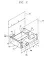
- the conventional exhaust type clothes dryer comprises: a cabinet 100 having an inlet 101 for introducing clothes and a door 11 for opening and closing the inlet 101 at a front side thereof; a drum 12 rotatably installed in the cabinet 100 and for accommodating clothes; a drum rotation device 14 for rotating the drum 12; an air circulation device 15 for sucking external air into the cabinet 100 and thereby introducing into the drum 12, and discharging air that has passed through the drum 12 outwardly; and a heater 16 for heating air introduced into the drum 12.
- the drum rotation device 14 includes: a driving motor 13 arranged at one side of the drum 12 and generating a rotational force; a pulley 14a installed at a rotational shaft of the driving motor 13; and a belt 14b installed to cover outer circumferences of the drum 12 and the pulley 14a, for transmitting a rotational force of the driving motor 13 to the drum 12.
- the air circulation device 15 includes: a suction port 15a formed at a rear panel of the cabinet 100, for sucking external air into the cabinet 100; a suction duct 15b respectively connected to inside of the cabinet 100 and an opening portion 12b formed at a rear side of the drum 12, for introducing air that has been sucked into the cabinet 100 into the drum 12; a fan 15c installed in the suction duct 15b and connected to the driving motor 13 thus to be rotated, for sucking external air and thereby introducing into the drum 12; an exhaust duct 15d connected to an opening portion 12a formed at a front side of the drum 12, for discharging air that has passed through the drum 12; and an exhaust port 150 connected to the exhaust duct 15d, for discharging air that has passed through the exhaust duct 15d to outside of the dryer.
- the exhaust port 150 is composed of: an exhaust chamber 152 connected to the exhaust duct 15d; first and second exhaust pipes 154 and 156 respectively diverged to the left side and the right side of the cabinet 100 from the exhaust chamber 152; and a third exhaust pipe 158 diverged to the rear side of the cabinet 100.
- Exits 154a and 156a of the first and second exhaust pipes 154 and 156 are arranged at positions linearly symmetric to each other with respect to a horizontal center axis H of the cabinet 100.
- the exits 154a and 156a are connected to exhaust holes 102a and 104a formed at a left panel 102 and a right panel 104 constituting the left wall and the right wall of the cabinet 100.
- the first and second exhaust pipes 154 and 156 guide air that has passed through the exhaust duct 15d and the exhaust chamber 152 to the left side or the right side of the cabinet 100.
- the first, second, and third exhaust pipes 154, 156, and 158 are respectively opened or closed according to an installation position of the clothes dryer, and thereby a direction of air discharged to outside of the dryer is set.
- the left panel 102 where the exhaust hole 102a is formed can not be assembled to the right side of the cabinet 100, and the right panel 104 where the exhaust hole 104a is formed can not be assembled to the left side of the cabinet 100. Therefore, even if the left panel 102 and the right panel 104 are formed as similar shapes to each other, a process for forming the exhaust hole 102a at the left panel 102 and a process for forming the exhaust hole 104a at the right panel 104 have to be individually performed. According to this, the number of fabrication processes is increased thus to lower an operation efficiency and to increase a fabrication cost.
- an object of the present invention is to provide a clothes dryer capable of reducing the number of fabrication processes and a fabrication cost by installing exhaust holes at the same position of lateral panels of a cabinet that forms an appearance.
- a clothes dryer comprising: a cabinet; a drum rotatably installed within the cabinet; and an exhaust port for discharging air having passed through the drum, wherein the exhaust port includes first and second exhaust pipes respectively diverged to both sides of the cabinet, and exits of the first and second exhaust pipes are arranged at positions rotationally symmetric to each other by 180° with respect to a vertical axis passing through the center of the cabinet.
- a clothes dryer comprising: a cabinet having a space therein as at least two panels are coupled to a periphery thereof; a drum rotatably installed within the cabinet; and at least two exhaust pipes connected to the drum, for discharging air having passed through the drum, wherein each panel is provided with an exhaust hole connected to the exhaust pipe, and the exhaust hole is arranged at the same position of each panel.
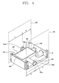
- the clothes dryer comprises: a cabinet 200 having an inlet 201 for introducing clothes and a door 21 for opening and closing the inlet 201 at a front side thereof; a drum 22 rotatably installed in the cabinet 200 and for accommodating clothes; a drum rotation device 24 for rotating the drum 22; an air circulation device 25 for sucking external air into the cabinet 200 and thereby introducing into the drum 22, and discharging air that has passed through the drum 22 outwardly; and a heater 26 for heating air introduced into the drum 22.
- the cabinet 200 has a structure that a left panel 202 and a right panel 204 that have the same width and height each other are coupled to the left side and the right side thereof (Refer to FIG. 4).
- the drum rotation device 24 includes: a driving motor 23 arranged at one side of the drum 22 and generating a rotational force; a pulley 24a installed at a rotational shaft of the driving motor 23; and a belt 24b installed to cover outer circumferences of the drum 22 and the pulley 24a, for transmitting a rotational force of the driving motor 23 to the drum 22.
- the air circulation device 25 includes: a suction port 25a formed at a rear panel of the cabinet 200, for sucking external air into the cabinet 200; a suction duct 25b respectively connected to inside of the cabinet 200 and an opening portion 22b formed at a rear side of the drum 22, for introducing air that has been sucked into the cabinet 200 into the drum 22; a fan 25c installed at the suction duct 25b and connected to the driving motor 23 thus to be rotated, for providing a suction force for sucking external air; an exhaust duct 25d connected to an opening portion 22a formed at a front side of the drum 22, for discharging air that has passed through the drum 22; a filter 27 installed at the opening portion 22a of the drum 22, for filtering foreign materials included in the air discharged from the drum 22 such as thread, etc.; and an exhaust port 250 connected to the exhaust duct 25d, for discharging air that has passed through the exhaust duct 25d to outside of the dryer.
- the exhaust port 250 includes: an exhaust chamber 252 connected to the exhaust duct 25d and having an expanded space therein; first and second exhaust pipes 254 and 256 respectively extended to the left side and the right side of the cabinet 200 from the exhaust chamber 252; and a third exhaust pipe 258 extended to a perpendicular direction to the extension direction of the first and second exhaust pipes 254 and 256, that is, extended to a rear side of the cabinet 200.
- the first and second exhaust pipes 254 and 256 guide air that has passed through the exhaust duct 25d and the exhaust chamber 252 to the right side or the left side of the cabinet 200.
- the third exhaust pipe 258 guides air that has passed through the exhaust chamber 252 to the rear side of the cabinet 200.
- the first, second, and third exhaust pipes 254, 256, and 258 are opened or closed according to an installation position of the clothes dryer. According to the open or close state of the first, second, and third exhaust pipes 254, 256, and 258, a discharge direction of air to outside of the dryer is set.
- the first, second, and third exhaust pipes 254, 256, and 258 are respectively connected to an additional connection duct (not shown). Through the connection duct, air introduced into the first, second, and third exhaust pipes 254, 256, and 258 is discharged to outside of the cabinet 200.
- Exits 254a and 256a of the first and second exhaust pipes 254 and 256 are connected to exhaust holes 202a and 204a respectively formed at the left panel 202 and the right panel 204 forming the left wall and the right wall of the cabinet 200.
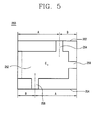
- the exits 254a and 256a of the first and second exhaust pipes 254 and 256 are arranged at positions rotationally symmetric to each other by 180° on the basis of a vertical axis passing through the center C of the cabinet 200. Also, the exhaust holes 202a and 204a respectively connected to the exits 254a and 256a of the first and second exhaust pipes 254 and 256 are arranged at positions rotationally symmetric to each other by 180° on the basis of the vertical axis passing through the center C of the cabinet 200.
- the exhaust holes 202a and 204a are formed at the same position of the left panel 202 and the right panel 204.
- the left panel 202 and the right panel 204 can be commonly used as the left wall or the right wall of the cabinet 200. Since the left panel 202 and the right panel 204 can be simultaneously fabricated through a single process, productivity and efficiency can be increased and a fabrication cost can be reduced.
- the exits 254a and 256a of the first and second exhaust pipes 254 and 256 are respectively formed at positions eccentric to the center ((A+B)/2) in a width direction of the cabinet 200.
- the exhaust holes 202a and 204a are also respectively formed at positions eccentric to the center ((A+B)/2) in the width direction of the left panel 202 and the right panel 204.
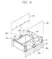
- the exits 254a and 256a of the first and second exhaust pipes 254 and 256 at the center ((A+B)/2) in the width direction of the cabinet 200.
- the exhaust holes 202a and 204a are also positioned at the center in the width direction of the left panel 202 and the right panel 204.
- the drum 22 connected to the driving motor 23, the pulley 24a, and the belt 24b is rotated thus to stir clothes accommodated in the drum 22.
- the driving motor 23 is operated, the fan 25c is operated and thereby external air is sucked into the cabinet 200 through the suction port 25a.
- the sucked air is introduced into the drum 22 through the suction duct 25b.
- the air introduced into the drum 22 is heated by the heater 26 installed in the suction duct 25b.
- the air of high temperature that has been introduced into the drum 22 deprives moisture of the clothes inside the drum 22, and the air including the moisture flows to the exhaust chamber 252 of the exhaust port 250 through the exhaust duct 25d.
- the air that has flown to the exhaust chamber 252 is discharged to outside of the dryer through the first, second, or the third exhaust pipes 254, 256, and 258 selectively opened and closed. By said process, the wet clothes inside the drum 22 are dried.
- a plurality of exhaust holes connected to a plurality of exhaust pipes for selectively discharging air that has passed through the drum are formed at a plurality of panels constituting the outer wall of the cabinet, and the exhaust holes are formed at the same position.
- the plurality of panels are fabricated as the same shape thus to be used to constitute the outer wall of the cabinet, thereby decreasing the number of fabrication processes, decreasing a fabrication cost, and increasing a productivity.
Landscapes
- Engineering & Computer Science (AREA)
- Textile Engineering (AREA)
- Detail Structures Of Washing Machines And Dryers (AREA)
Applications Claiming Priority (2)
| Application Number | Priority Date | Filing Date | Title |
|---|---|---|---|
| KR1020040033176A KR100556805B1 (ko) | 2004-05-11 | 2004-05-11 | 의류 건조기 |
| KR2004033176 | 2004-05-11 |
Publications (2)
| Publication Number | Publication Date |
|---|---|
| EP1595993A1 true EP1595993A1 (de) | 2005-11-16 |
| EP1595993B1 EP1595993B1 (de) | 2010-09-15 |
Family
ID=34931413
Family Applications (1)
| Application Number | Title | Priority Date | Filing Date |
|---|---|---|---|
| EP04292298A Expired - Lifetime EP1595993B1 (de) | 2004-05-11 | 2004-09-24 | Wäschetrockner |
Country Status (5)
| Country | Link |
|---|---|
| US (1) | US7069669B2 (de) |
| EP (1) | EP1595993B1 (de) |
| KR (1) | KR100556805B1 (de) |
| CN (1) | CN100540794C (de) |
| DE (1) | DE602004029139D1 (de) |
Families Citing this family (15)
| Publication number | Priority date | Publication date | Assignee | Title |
|---|---|---|---|---|
| KR100556804B1 (ko) * | 2004-05-11 | 2006-03-10 | 엘지전자 주식회사 | 의류 건조기용 배기챔버 |
| DE102004055942A1 (de) * | 2004-11-19 | 2006-05-24 | BSH Bosch und Siemens Hausgeräte GmbH | Wäschetrockner |
| KR100662369B1 (ko) * | 2004-11-30 | 2007-01-02 | 엘지전자 주식회사 | 열풍공급용 옷걸이가 구비된 복합식 건조장치 |
| WO2006062262A1 (en) * | 2004-12-06 | 2006-06-15 | Lg Electronics Inc. | Clothes dryer |
| DE102005013052A1 (de) * | 2005-03-18 | 2006-09-21 | BSH Bosch und Siemens Hausgeräte GmbH | Wäschetrockenmaschine |
| KR100638936B1 (ko) * | 2005-03-31 | 2006-10-25 | 엘지전자 주식회사 | 건조기의 캐비닛 구조 |
| KR100697083B1 (ko) * | 2005-04-06 | 2007-03-20 | 엘지전자 주식회사 | 건조 겸용 세탁기 |
| DE102006023389A1 (de) * | 2006-05-17 | 2007-11-22 | Herbert Kannegiesser Gmbh | Verfahren und Vorrichtung zum Behandeln, vorzugsweise Waschen, Schleudern und/oder Trocknen, von Wäsche |
| CA2554497C (en) * | 2006-07-28 | 2010-02-16 | Mabe Canada Inc. | Blower wheel attachment for clothes dryer |
| US20090000139A1 (en) * | 2007-06-29 | 2009-01-01 | Hodges Timothy M | Clothes dryer air intake system |
| KR101308510B1 (ko) * | 2007-11-05 | 2013-09-12 | 동부대우전자 주식회사 | 히터 내장형 흡기관을 구비하는 건조기 |
| KR101256145B1 (ko) * | 2007-11-05 | 2013-04-23 | 동부대우전자 주식회사 | 히터 내장형 흡기관을 구비하는 건조기 |
| US7665228B2 (en) * | 2007-12-19 | 2010-02-23 | Electrolux Home Products, Inc. | Flow enhancing air duct and grill for laundry dryer |
| KR20180136763A (ko) * | 2017-06-15 | 2018-12-26 | 주식회사 대우전자 | 벽걸이형 드럼 세탁기 |
| CN109402986A (zh) * | 2017-08-18 | 2019-03-01 | 青岛海尔洗衣机有限公司 | 烘干机及洗衣机 |
Citations (2)
| Publication number | Priority date | Publication date | Assignee | Title |
|---|---|---|---|---|
| US4753018A (en) * | 1986-10-29 | 1988-06-28 | Whirlpool Corporation | Multivent system for dryer exhaust |
| US4875298A (en) * | 1988-10-14 | 1989-10-24 | Wright Robert L | Preheater for clothes dryer |
Family Cites Families (6)
| Publication number | Priority date | Publication date | Assignee | Title |
|---|---|---|---|---|
| US2617203A (en) * | 1948-10-13 | 1952-11-11 | Orval D Murray | Drier |
| US3364585A (en) * | 1965-06-07 | 1968-01-23 | Gen Motors Corp | Dryer sprinkle system |
| JPS5679294U (de) | 1979-11-21 | 1981-06-27 | ||
| JPS6443895U (de) | 1987-09-09 | 1989-03-16 | ||
| US5042172A (en) * | 1987-12-29 | 1991-08-27 | Whirlpool Corporation | Clothes dryer with flexible exhaust duct system |
| KR100451742B1 (ko) * | 2002-08-13 | 2004-10-08 | 엘지전자 주식회사 | 의류건조기 |
-
2004
- 2004-05-11 KR KR1020040033176A patent/KR100556805B1/ko not_active Expired - Fee Related
- 2004-09-24 DE DE602004029139T patent/DE602004029139D1/de not_active Expired - Lifetime
- 2004-09-24 EP EP04292298A patent/EP1595993B1/de not_active Expired - Lifetime
- 2004-10-06 US US10/958,330 patent/US7069669B2/en not_active Expired - Fee Related
-
2005
- 2005-01-11 CN CNB2005100039981A patent/CN100540794C/zh not_active Expired - Fee Related
Patent Citations (2)
| Publication number | Priority date | Publication date | Assignee | Title |
|---|---|---|---|---|
| US4753018A (en) * | 1986-10-29 | 1988-06-28 | Whirlpool Corporation | Multivent system for dryer exhaust |
| US4875298A (en) * | 1988-10-14 | 1989-10-24 | Wright Robert L | Preheater for clothes dryer |
Also Published As
| Publication number | Publication date |
|---|---|
| CN1696388A (zh) | 2005-11-16 |
| CN100540794C (zh) | 2009-09-16 |
| DE602004029139D1 (de) | 2010-10-28 |
| KR20050108115A (ko) | 2005-11-16 |
| US20050252030A1 (en) | 2005-11-17 |
| KR100556805B1 (ko) | 2006-03-10 |
| US7069669B2 (en) | 2006-07-04 |
| EP1595993B1 (de) | 2010-09-15 |
Similar Documents
| Publication | Publication Date | Title |
|---|---|---|
| AU2006241367B2 (en) | A single body washing machine and dryer device and a method for controlling the same | |
| EP1595993B1 (de) | Wäschetrockner | |
| US8266816B2 (en) | Clothes dryer and door thereof | |
| US8844163B2 (en) | Laundry treating machine with basement portion providing airflow paths | |
| KR102052373B1 (ko) | 의류처리장치 | |
| CN113355841A (zh) | 堆叠式衣物处理装置 | |
| US20120049705A1 (en) | Laundry Treating Machine with Bottom-Side Air Passage | |
| KR20100034077A (ko) | 의류건조기 | |
| KR20180066742A (ko) | 의류 건조기 | |
| US12139844B2 (en) | Clothing dryer | |
| US20050132603A1 (en) | Dryer | |
| EP1584732B1 (de) | Wäschetrockner | |
| CN1936158A (zh) | 衣物干燥装置 | |
| US20250263878A1 (en) | Washing machine with drying function | |
| KR101156706B1 (ko) | 의류건조기 | |
| CN114096708A (zh) | 烘干机 | |
| CN209958110U (zh) | 衣物处理设备 | |
| CN111748985B (zh) | 衣物处理设备 | |
| EP1595994A1 (de) | Wäschetrockner | |
| EP3943656B1 (de) | Wäschebehandlungsvorrichtung | |
| KR100701181B1 (ko) | 끼움 결합방식의 프레임 탑이 구비되는 건조기 | |
| EP3674474B1 (de) | Wäschebehandlungsvorrichtung | |
| KR20230102913A (ko) | 건조 겸용 세탁기 | |
| US20260125843A1 (en) | Drying Air Return Duct For A Laundry Appliance | |
| KR20040045114A (ko) | 빨래건조기의 프론트 캐비닛과 프론트 서포트간의 조립구조 |
Legal Events
| Date | Code | Title | Description |
|---|---|---|---|
| PUAI | Public reference made under article 153(3) epc to a published international application that has entered the european phase |
Free format text: ORIGINAL CODE: 0009012 |
|
| 17P | Request for examination filed |
Effective date: 20041001 |
|
| AK | Designated contracting states |
Kind code of ref document: A1 Designated state(s): AT BE BG CH CY CZ DE DK EE ES FI FR GB GR HU IE IT LI LU MC NL PL PT RO SE SI SK TR |
|
| AX | Request for extension of the european patent |
Extension state: AL HR LT LV MK |
|
| AKX | Designation fees paid |
Designated state(s): DE FR GB |
|
| 17Q | First examination report despatched |
Effective date: 20070529 |
|
| GRAP | Despatch of communication of intention to grant a patent |
Free format text: ORIGINAL CODE: EPIDOSNIGR1 |
|
| GRAS | Grant fee paid |
Free format text: ORIGINAL CODE: EPIDOSNIGR3 |
|
| GRAA | (expected) grant |
Free format text: ORIGINAL CODE: 0009210 |
|
| AK | Designated contracting states |
Kind code of ref document: B1 Designated state(s): DE FR GB |
|
| REG | Reference to a national code |
Ref country code: GB Ref legal event code: FG4D |
|
| REF | Corresponds to: |
Ref document number: 602004029139 Country of ref document: DE Date of ref document: 20101028 Kind code of ref document: P |
|
| PLBE | No opposition filed within time limit |
Free format text: ORIGINAL CODE: 0009261 |
|
| STAA | Information on the status of an ep patent application or granted ep patent |
Free format text: STATUS: NO OPPOSITION FILED WITHIN TIME LIMIT |
|
| 26N | No opposition filed |
Effective date: 20110616 |
|
| REG | Reference to a national code |
Ref country code: DE Ref legal event code: R097 Ref document number: 602004029139 Country of ref document: DE Effective date: 20110616 |
|
| PGFP | Annual fee paid to national office [announced via postgrant information from national office to epo] |
Ref country code: GB Payment date: 20120816 Year of fee payment: 9 |
|
| PGFP | Annual fee paid to national office [announced via postgrant information from national office to epo] |
Ref country code: FR Payment date: 20120822 Year of fee payment: 9 Ref country code: DE Payment date: 20120815 Year of fee payment: 9 |
|
| GBPC | Gb: european patent ceased through non-payment of renewal fee |
Effective date: 20130924 |
|
| REG | Reference to a national code |
Ref country code: DE Ref legal event code: R119 Ref document number: 602004029139 Country of ref document: DE Effective date: 20140401 |
|
| REG | Reference to a national code |
Ref country code: FR Ref legal event code: ST Effective date: 20140530 |
|
| PG25 | Lapsed in a contracting state [announced via postgrant information from national office to epo] |
Ref country code: GB Free format text: LAPSE BECAUSE OF NON-PAYMENT OF DUE FEES Effective date: 20130924 |
|
| PG25 | Lapsed in a contracting state [announced via postgrant information from national office to epo] |
Ref country code: DE Free format text: LAPSE BECAUSE OF NON-PAYMENT OF DUE FEES Effective date: 20140401 Ref country code: FR Free format text: LAPSE BECAUSE OF NON-PAYMENT OF DUE FEES Effective date: 20130930 |