EP1595966A1 - Steel pipe for bearing elements, and methods for producing and cutting the same - Google Patents
Steel pipe for bearing elements, and methods for producing and cutting the same Download PDFInfo
- Publication number
- EP1595966A1 EP1595966A1 EP04705918A EP04705918A EP1595966A1 EP 1595966 A1 EP1595966 A1 EP 1595966A1 EP 04705918 A EP04705918 A EP 04705918A EP 04705918 A EP04705918 A EP 04705918A EP 1595966 A1 EP1595966 A1 EP 1595966A1
- Authority
- EP
- European Patent Office
- Prior art keywords
- steel
- steel tube
- cutting
- less
- bearing element
- Prior art date
- Legal status (The legal status is an assumption and is not a legal conclusion. Google has not performed a legal analysis and makes no representation as to the accuracy of the status listed.)
- Granted
Links
Images


Classifications
-
- C—CHEMISTRY; METALLURGY
- C22—METALLURGY; FERROUS OR NON-FERROUS ALLOYS; TREATMENT OF ALLOYS OR NON-FERROUS METALS
- C22C—ALLOYS
- C22C38/00—Ferrous alloys, e.g. steel alloys
- C22C38/02—Ferrous alloys, e.g. steel alloys containing silicon
-
- C—CHEMISTRY; METALLURGY
- C21—METALLURGY OF IRON
- C21D—MODIFYING THE PHYSICAL STRUCTURE OF FERROUS METALS; GENERAL DEVICES FOR HEAT TREATMENT OF FERROUS OR NON-FERROUS METALS OR ALLOYS; MAKING METAL MALLEABLE, e.g. BY DECARBURISATION OR TEMPERING
- C21D8/00—Modifying the physical properties of ferrous metals or ferrous alloys by deformation combined with, or followed by, heat treatment
- C21D8/10—Modifying the physical properties of ferrous metals or ferrous alloys by deformation combined with, or followed by, heat treatment during manufacturing of tubular bodies
-
- C—CHEMISTRY; METALLURGY
- C22—METALLURGY; FERROUS OR NON-FERROUS ALLOYS; TREATMENT OF ALLOYS OR NON-FERROUS METALS
- C22C—ALLOYS
- C22C38/00—Ferrous alloys, e.g. steel alloys
- C22C38/04—Ferrous alloys, e.g. steel alloys containing manganese
-
- C—CHEMISTRY; METALLURGY
- C22—METALLURGY; FERROUS OR NON-FERROUS ALLOYS; TREATMENT OF ALLOYS OR NON-FERROUS METALS
- C22C—ALLOYS
- C22C38/00—Ferrous alloys, e.g. steel alloys
- C22C38/18—Ferrous alloys, e.g. steel alloys containing chromium
-
- C—CHEMISTRY; METALLURGY
- C22—METALLURGY; FERROUS OR NON-FERROUS ALLOYS; TREATMENT OF ALLOYS OR NON-FERROUS METALS
- C22C—ALLOYS
- C22C38/00—Ferrous alloys, e.g. steel alloys
- C22C38/18—Ferrous alloys, e.g. steel alloys containing chromium
- C22C38/22—Ferrous alloys, e.g. steel alloys containing chromium with molybdenum or tungsten
-
- C—CHEMISTRY; METALLURGY
- C21—METALLURGY OF IRON
- C21D—MODIFYING THE PHYSICAL STRUCTURE OF FERROUS METALS; GENERAL DEVICES FOR HEAT TREATMENT OF FERROUS OR NON-FERROUS METALS OR ALLOYS; MAKING METAL MALLEABLE, e.g. BY DECARBURISATION OR TEMPERING
- C21D1/00—General methods or devices for heat treatment, e.g. annealing, hardening, quenching or tempering
- C21D1/26—Methods of annealing
- C21D1/32—Soft annealing, e.g. spheroidising
-
- Y—GENERAL TAGGING OF NEW TECHNOLOGICAL DEVELOPMENTS; GENERAL TAGGING OF CROSS-SECTIONAL TECHNOLOGIES SPANNING OVER SEVERAL SECTIONS OF THE IPC; TECHNICAL SUBJECTS COVERED BY FORMER USPC CROSS-REFERENCE ART COLLECTIONS [XRACs] AND DIGESTS
- Y10—TECHNICAL SUBJECTS COVERED BY FORMER USPC
- Y10S—TECHNICAL SUBJECTS COVERED BY FORMER USPC CROSS-REFERENCE ART COLLECTIONS [XRACs] AND DIGESTS
- Y10S148/00—Metal treatment
- Y10S148/902—Metal treatment having portions of differing metallurgical properties or characteristics
- Y10S148/909—Tube
-
- Y—GENERAL TAGGING OF NEW TECHNOLOGICAL DEVELOPMENTS; GENERAL TAGGING OF CROSS-SECTIONAL TECHNOLOGIES SPANNING OVER SEVERAL SECTIONS OF THE IPC; TECHNICAL SUBJECTS COVERED BY FORMER USPC CROSS-REFERENCE ART COLLECTIONS [XRACs] AND DIGESTS
- Y10—TECHNICAL SUBJECTS COVERED BY FORMER USPC
- Y10S—TECHNICAL SUBJECTS COVERED BY FORMER USPC CROSS-REFERENCE ART COLLECTIONS [XRACs] AND DIGESTS
- Y10S384/00—Bearings
- Y10S384/90—Cooling or heating
- Y10S384/912—Metallic
Definitions
- the present invention relates to steel tubes having excellent machinability to be used for bearing element parts, and relates to a method of manufacturing as well as machining the same. More specifically, it relates to steel tubes having excellent machinability that is suitable for use of bearing element parts such as races, shafts and rollers, and relates to a method of manufacturing as well as machining the same.
- high Cr (chromium) bearing steel such as SUJ2, specified in JIS G 4805 Standard is widely used in general.
- bearing steel is subjected to processing by means of hot rolling and the like, and then to spheroidizing annealing for the purpose of softening, followed by processing such as cold rolling, cold drawing, cold forging and machining, which finally undergoes the heat treatment comprising quenching and tempering at low temperature, thus resulting in having desired mechanical properties.
- a free-cutting metal element (a metal element to act for enhancing machinability) such as Pb and S is well known to improve machinability when it is added independently or in combination with the other(s).
- bearings to be used for industrial machineries, automobiles or the like are subjected to repetitively high surface pressure.
- the addition of above free-cutting element(s) will cause a fatigue life in rolling contact to substantially decrease.
- the above free-cutting metal element generally causes hot workability to decrease, thereby becoming more of an issue that surface cracking and defects are likely to be generated during hot working process such as hot rolling for bearing steels.
- the bearing steel having a B content which is specified in the above Japanese Patent Application Publication No. 03-56641, namely 0.004 - 0.020% in weight, is not commercially and reliably processed to be bearing
- Japanese Patent No. 3245045 a bearing steel having excellent machinability as well as cold workability and a method for manufacturing the same is disclosed, wherein the number of carbides in the metal structure and the hardness are adjusted by the heat treatment to be applied under specific condition.
- a slow heating or an isothermally holding in its heat-up step is required. In this regard, the annealing time becomes longer, thus reducing the productivity.
- the disclosed technologies above could at least provide a bearing steel tube having excellent machinability to be used for bearing element parts. But, as afore-mentioned, the productivity as well as quality will potentially become more of an issue.
- the present invention was made in view of above status quo, and its object is to provide a steel tube having excellent machinability which is suitable for use of bearing element parts such as races, rollers and shafts, without particularly adding free-cutting metal elements or without reducing productivity by applying an ordinary annealing time of 10 - 20 hours or so which is similar to the conventional case. Further, it is also an object to provide a method of manufacturing as well as machining said steel tube.
- the present inventors to achieve the above object, have intensively investigated and studied on the microstructure, especially texture, as well as machinability of a steel tube for bearing element parts to be subjected to cutting-machining process, thereby ending up in findings described in (a) - (f) as below.
- the present invention is consummated based on the above findings, and the gist resides in a steel tube for bearing element parts described in following (1) - (3), a method of manufacturing the same described in following (4), and a method of machining the same described in following (5).
- Fig. 1 is a diagram explaining "a plane in parallel with the circumferential direction of the steel tube".
- the "plane in parallel with the circumferential direction of the steel tube” according to the present invention is defined to be “a plane in parallel with the plane forming outer surface of steel tube in the specimen 2 that is flattened out for correcting the curvature of the halved steel tube 1 which is obtained by longitudinally splitting a ring-like steel tube, which is made by ring-cutting, and a plane positioned at 0.3 mm or more away from either plane forming outer surface or inner surface of the steel tube”.
- the region less than 0.3 mm away from with either plane which forms an outer surface or inner surface is excluded for the reason that an anomalous layer such as a decarburized layer occasionally exists in that region.
- an accumulation intensity of ⁇ 211 ⁇ face designates the quotient of an integrated reflection intensity of ⁇ 211 ⁇ face divided by 1700 (cps), wherein the intensity is measured for the plane in parallel with the circumferential direction of steel tube as defined above by X-ray diffraction method with the parameters described in (i) - (vi) as below (hereinafter referred to as "the specific X-ray diffraction method"):
- the divisor 1700 (cps) set forth as above is the value of the integrated reflection intensity of ⁇ 211 ⁇ face obtained by measurement in accordance with the above specific X-ray diffraction method for a polished specimen (hereinafter referred to as "Standard Specimen") which is made in such a way that a hot forged bar of 60 mm in diameter made of Steel D shown in Table 1, described later on, is heated at 1200°C for 30 min followed by cooling in the open air down to room temperature, heated again at 780°C for 4 hours followed by step cooling comprising first stage cooling down to 660°C with cooling rate of 10°C /hr and an immediate second cooling down to room temperature in the open air, and then the in-process bar is subjected to cutting and polishing for the cross-section of the round bar to be provided for measurement.
- Desired mechanical properties are given to bearing steel materials (bearing element parts) by applying quenching and tempering at low temperature, but in case that C content is less than 0.6%, the obtained hardness after above quenching/tempering becomes low so that the required hardness for bearing element parts, that is, Rockwell C Hardness to be not less than 58, can not be achieved.
- C content exceeds 1.1%, the melting startup temperature of the steel decreases, thereby causing cracking and defects during hot tube making process to generate frequently.
- C content is specified to be in the range of 0.6 - 1.1%.
- Si is an effective element for enhancing a fatigue life in rolling contact and also an important element as a deoxidizer. Si has an effect to enhance quench hardenability of steel too. However, in case that the content thereof is less than 0.1%, the above effect can not be expected. On the other hand, in case that the content of Si exceeds 1.5%, it takes long time to descale after hot working process or spheroidizing annealing, thereby incurring substantial fall of productivity. Thus, Si content is specified to be in the range of 0.1 - 1.5%. Mn: 0.2 - 1.5%
- Mn serves to enhance quench hardenability of steel and is a required element to prevent hot embrittlement due to S element.
- Mn content shall be 0.2% or more.
- Mn content exceeds 1.0% the center segregation of not only Mn but also C is induced to generate.
- Mn content exceeding 1.5% results in notable center segregation of Mn as well as C, which causes the melting startup temperature of steel to decrease, thereby ending up in frequent generation of cracking and defects during hot tube making process.
- Mn content is specified to be in the range of 0.2 - 1.5%. It is further preferable that Mn content is limited in the range of 0.2 - 1.0%.
- Cr has an effect to enhance quench hardenability of steel. And Cr is very likely to be enriched in cementite, which thus causes cementite to be hardened by the Cr enrichment, thereby serving to enhance the machinability. However, Cr content below 0.2% is ineffective for the above aspect. On the other hand, in case the content exceeds 1.6%, the center segregation of not only Cr but also C is induced to generate. In particular, Cr content exceeding 2.0% results in marked center segregation of Cr as well as C, which causes the melting startup temperature of steel to decrease, thereby ending up in frequent generation of cracking and defects during hot tube making process. Thus, Cr content is specified to be in the range of 0.2 - 2.0%. S: 0.003 - 0.020%
- S combines with Mn to form MnS, wherein said MnS plays the role of lubrication in cutting-machining process, thereby enhancing a tool life.
- S content is 0.003% or more.
- S content is specified to be in the range of 0.003 - 0.020%.
- Al has a strong deoxidizing effect, it is an effective element to reduce oxygen content in steel. To that end, it is necessary that Al content is 0.005% or more. On the other hand, Al tends to form non-metallic inclusions, which causes a fatigue life in rolling-contact to decrease. In particular, in case the content exceeds 0.05%, significantly large non-metallic inclusions are likely to be formed, thereby resulting in marked reduction of a fatigue life in rolling-contact. Thus, Al content is specified to be in the range of 0.005 - 0.05%. Mo: 0 - 0.5%
- Mo content is 0.03% or more. Nonetheless, in case the content exceeds 0.5%, an excessive quench hardenability is obtained, which causes martensite to easily be formed after hot rolling process, namely after hot tube making process, thereby becoming a cause of generation of cracking.
- Mo content is specified to be in the range of 0 - 0.5%
- Mo content is specified to be in the range of 0.03 - 0.5%.
- Ti, P, N and O which are deemed as impurities according to the present invention, are specified as below. Ti: 0.003% or less
- Ti combines with N to form TiN, which reduces a fatigue life in rolling contact.
- Ti content is specified to be 0.003% or less.
- it is much more preferable for Ti content is 0.002% or less.
- P segregates at grain boundaries and reduces the melting point of metal in the vicinity of grain boundaries.
- the content exceeds 0.02%, the melting point of metal in the vicinity of grain boundaries decreases significantly, thereby causing cracking and defects during hot tube making process to frequently generate. Therefore, P content is specified to be 0.02% or less. It is much more preferable for the P content to be 0.01% or less. N: 0.012% or less
- N likely combines with Ti and Al to form TiN and AlN.
- O (oxygen) forms oxide-type inclusions, which reduces a fatigue life in rolling contact.
- the content exceeds 0.0015%, the fatigue life in rolling contact reduces markedly. Therefore, O content is specified to be 0.0015% or less. It is desirable for O content to be as low as possible, thus it is preferable for the content to be 0.0010% or less.
- the chemical compositions besides above metal elements could comprises, for example, Ni: 1% or less, Cu: 0.5% or less, V: 0.1% or less, Nb: 0.05% or less, Ca: 0.003% or less and Mg: 0.003% or less so as to ensure a required feature as a finished product as well as to make it possible to obtain steel tubes having excellent machinability.
- these elements are supplementarily added into the chemical compositions in order to enhance the feature as finished products or to enhance the machinability of steel tubes, it is preferable for these elements to be respectively limited as specified by Ni: 0.1 - 1%, Cu: 0.05 - 0.5%, V: 0.02 - 0.1%, Nb: 0.005 - 0.05%, Ca: 0.0003 - 0.003% and Mg: 0.0003 - 0.003%.
- Ni, Cu, V and Nb can be added in combination, not to mention independently.
- Ca and Mg can be added in combination, not to mention independently.
- at least one element out of Ni, Cu, V and Nb can be added in combination with either or both of Ca and Mg.
- An accumulation intensity of ⁇ 211 ⁇ face in the plane in parallel with the circumferential direction of steel tube correlates with a tool life in cutting-machining, and a satisfactory tool life can be assured when the above accumulation intensity of ⁇ 211 ⁇ face in the plane in parallel with the circumferential direction becomes 1.5 or more.
- the present inventors cut steel tubes having various chemical compositions into rings of 20 mm in length, split these rings into halves on the plane in parallel with longitudinal direction, and then make these halves flattened to prepare flat specimens. Further, each surface of these specimens corresponding to the outer surface of steel tube is polished taking off the metal of about 0.5 mm depth to obtain a mirror finished surface, namely "a plane in parallel with the circumferential direction of steel tube", which is subsequently measured by use of an ordinary X-ray diffraction method to obtain each pole figure of (200) and (110), thereby determining face orientation of texture.
- Fig. 2 is a diagram showing a relationship between a tool life and an accumulation intensity of ⁇ 211 ⁇ face in the plane in parallel with the circumferential direction of steel tube. Based on the relationship in Fig. 2, in case of "A First Steel Tube" according to the present invention, an accumulation intensity of ⁇ 211 ⁇ face in the plane in parallel with the circumferential direction of steel tube is specified to be 1.5 or more. Further, it is preferable for above accumulation intensity to be 2.0 or more.
- the upper limit of the accumulation intensity of ⁇ 211 ⁇ face is not specifically set forth, but it costs a lot to achieve 4.0 or more under conditions for commercial mass production. For that reason, it is preferable for the accumulation intensity of ⁇ 211 ⁇ face to be less than 4.0.
- the impact value at ambient temperature is specified to be 10 J/cm 2 or less in addition to making the texture of ⁇ 211 ⁇ face grow in the plane in parallel with the circumferential direction of steel tube.
- Spheroidizing annealing is carried out for softening purpose after hot-rolling process, and a common spheroidizing annealing can be applied.
- a common spheroidizing annealing can be applied.
- the present inventors applied a common spheroidizing annealing after hot-rolling process for steel tubes having various chemical compositions, and then applied cold working process and heat treatment under various conditions to investigate the texture by the procedure described in (B) as above.
- Figs. 4 and 5 are obtained from the collation of some examples of the results by above investigation.
- Fig. 4 is a diagram showing how the cross-section area reduction rate of steel tube as well as the wall thickness reduction rate of steel tube affect the growth of ⁇ 211 ⁇ texture.
- steps comprising a common spheroidizing annealing after hot-rolling process of steel tubes having chemical compositions conforming to the provisions described in above (A), cold working under various conditions, and subsequent heat treatment consisting of heating at 680°C - A 1 point and holding for 5 - 40 minutes, the extent how the cross-section area reduction rate of steel tube as well as the wall thickness reduction rate of steel tube affect the growth of ⁇ 211 ⁇ texture is collated.
- a symbol o denotes the case that an obtained accumulation intensity of ⁇ 211 ⁇ face is 1.5 or more
- a symbol ⁇ denotes the case other than that (namely, an accumulation intensity of ⁇ 211 ⁇ face is less than 1.5) in above category.
- the case the obtained accumulation intensity of ⁇ 211 ⁇ face is 1.5 or more is simply represented by ⁇ 211 ⁇ 1.5 or more.
- the cross-section reduction rate of steel tube (cross-section area reduction rate) has only to be 50% or more and the wall thickness reduction rate of steel tube has only to be 30% or more as a condition of cold working after spheroidizing annealing.
- the upper limits of both cross-section reduction rate of steel tube and wall thickness reduction rate of steel tube are preferably specified to be 80% and 70% respectively.
- Fig. 5 is a diagram showing how the heat treatment temperature (heating temperature) and its holding time affect the growth of ⁇ 211 ⁇ texture.
- a cold working process in such a way as described before that the cross-section reduction rate of steel tube is 50 - 80% and the wall thickness reduction rate of steel tube is 30 - 70%, and subsequent heat treatment under various conditions, the extent how the heat treatment conditions, namely the heat treatment temperature and its holding time affect the growth of ⁇ 211 ⁇ texture is collated.
- a symbol o denotes the case that an obtained accumulation intensity of ⁇ 211 ⁇ face is 1.5 or more
- a symbol ⁇ denotes the case other than that (namely, an accumulation intensity of ⁇ 211 ⁇ face is less than 1.5) in above category.
- the numbers appearing on the top of o and ⁇ in case that the heating temperature is 740 - 780°C and its holding time is 10 - 20 minutes denote A 1 points (°C).
- the method comprises the steps of spheroidizing annealing after hot-rolling process, cold working in such a way that the cross-section reduction rate of steel tube is 50 - 80% and the wall thickness reduction rate of steel tube is 30 - 70%, and subsequent heating at 680°C - A 1 point for 5 - 40 minutes in duration.
- the present inventors applied hot-rolling process for steel having chemical compositions conforming to the provisions described in above (A), a common spheroidizing annealing after that, and then cold working process along with heat treatment with conditions conforming to the provisions described in above (D) to investigate the texture by the procedure described in above (B).
- the steel tube thus obtained is subjected to groove-cutting with same parameters as above (B) except the variation of a coating layer on the chip in order to measure a tool life.
- a coating layer onto relief face only of above cemented carbide chip which are TiN, TiAlN, and a multi-laminated coating layer by depositing TiN and AlN alternately with a cycle of 2.5 nm, wherein each Vicker's Hardness is 2200, 3100 and 3900 respectively.
- Fig. 6 is a diagram showing a relationship between a tool life and Vicker's Hardness of coating layer on a cemented carbide chip. From this diagram, it turns out that the cemented carbide chip having a coating layer with 3000 or more in Vicker's Hardness has only to be used in order to extend a tool life.
- the cemented carbide chip having a coating layer with 3000 or more in Vicker's Hardness be used for cutting-machining. Further, in case the Vicker's Hardness is 3800 or more, the tool life can be increasingly enhanced. Thus, it is more preferable that the cemented carbide chip having a coating layer with 3800 or more in Vicker's Hardness be used for cutting-machining.
- the upper limit of the Vicker's Hardness is not specified in particular, it is costlier to form a coating layer with 4500 or more in Vicker's Hardness. For that reason, it is preferable that the Vicker's Hardness of the coating layer be less than 4500.
- Steels B - D, Steel F, Steel H, Steel K and Steel M shown in above Tables 1 and 2 conform to the claimed ranges of chemical compositions according to the present invention.
- Steel A, Steel E, Steel G, Steel I, Steel J, Steel L and Steels N - T represent comparative examples, wherein any element(s) in chemical compositions falls out of the claimed ranges according to the present invention.
- each ingot of above Steels A ⁇ C and E ⁇ T that were made by 180 kg furnace was hot forged by an ordinary method to be a bar of 60 mm in diameter.
- the ingot of Steel D that was melted by a 70-ton converter was subjected to breakdown and hot forging processes to be a billet of 178 mm in diameter, followed by an ordinary hot forging process to produce a bar of 60 mm in diameter.
- a 60 mm diameter bar was cut into pieces of 300 mm in length, which were then subjected to spheroidizing annealing with various conditions.
- the conditions of spheroidizng annealing in case that Cr content is 0.8% or more, the bars were heated at 780°C for four hours, while in case that Cr content is less than 0.8%, those were heated at 760°C for four hours. In either case, after heating for four hours, the bars were cooled at a rate of 10°C/hr down to 660°C and then released to the open air.
- the bars thus treated by spheroidizing annealing were subjected to machining to produce test specimens of 58 mm diameter by 5.2 mm thickness, which were heated at 820°C for 30 min followed by immediate oil quenching and subsequent tempering at 160°C for one hour.
- test specimens (58 mm diameter, 5.2 mm thickness) that were subjected to quenching and tempering as above were mirror polished and underwent a fatigue test in rolling contact.
- the conditions of the fatigue test in rolling contact are shown in (i) ⁇ (v) as below.
- Table 3 shows the result of rolling contact fatigue tests.
- Classification Test No. Steel Fatigue Life in Rolling Contact (cycles) C 1 *A # 4.5 x 10 6 I 2 B 1.3 x 10 7 I 3 C 1.9 x 10 7 I 4 D 3.7 x 10 7 C 5 *E 2.3 x 10 7 I 6 F 4.6 x 10 7 C 7 *G 5.1 x 10 7 I 8 H 1.2 x 10 7 C 9 *I 3.2 x 10 7 C 10 *J 3.5 x 10 7 I 11 K 4.9 x 10 7 C 12 *L 6.0 x 10 7 I 13 M 1.8 x 10 7 C 14 *N # 8.4 x 10 6 C 15 *O # 6.3 x 10 6 C 16 *P 1.9 x 10 7 C 17 *Q 4.1 x 10 7 C 18 *R 2.7 x 10 7 C 19 *S # 7.5 x 10 6 C 20 *T # 5.3 x 10 6 C and I denote "Comparative Example” and "Inventive Example” respectively.
- a symbol * denote
- Test No. 1 of Steel A having C content below the specified value and Test Nos. 14, 15, 19 and 20 which are conducted for Steels N, O, S and T respectively where Al, Ti, N and O exceed the specified limit by the present invention respectively, do not satisfy the target of L 10 endurance limit, 1 x 10 7 , thereby proving to have an inferior fatigue life in rolling contact.
- the round bar of 60 mm in diameter as hot forged is heated at 1200°C for 20 minutes and subjected to hot tube making process with finishing temperature of 850 - 950°C to obtain 39.1 mm diameter by 5.90 mm wall thickness, finally being cooled down in the open air after hot tube making process.
- the temperature thereof rises by heat generation by deformation itself during hot tube making process, and likely exceeds the melting point locally, which is attributed to likely generation of defects.
- the inside surface of the obtained steel tube of 39.1 mm diameter by 5.90 mm wall thickness is inspected visually for defects. Furthermore, the visual inspection is also carried out to check whether or not cracking generate on both outside and inside surface.
- Table 4 shows the inspection results of inside surface for defects as well as of both outside diameter and inside diameter for the presence of cracking.
- steel tubes made of Steels B - D, F, G, H, K, M and Q, where neither any inside surface defect nor any cracking on both outside and inside surfaces are detected are subjected to descaling treatment by an ordinary acid pickling, to check whether or not any scale remains.
- descaling treatment by an ordinary acid pickling, to check whether or not any scale remains.
- Table 4 the presence of remaining scale is also listed.
- Steel tubes thus obtained are subjected to spheroidizing annealing and successive descaling by an ordinary acid pickling, followed by cold drawing or cold rolling with cold pilger mill to obtain steel tubes of 30.0 mm in diameter by 3.0 mm in wall thickness.
- the above spheroidizing annealing is carried out in heating at 780°C for 4 hours in case of Steel whose Cr content is 0.8% or more, and at 760°C for 4 hours in case of Steel whose Cr content is less than 0.8%.
- the cooling rate in both cases is 10°C/hour down to 660°C and then released in the open air.
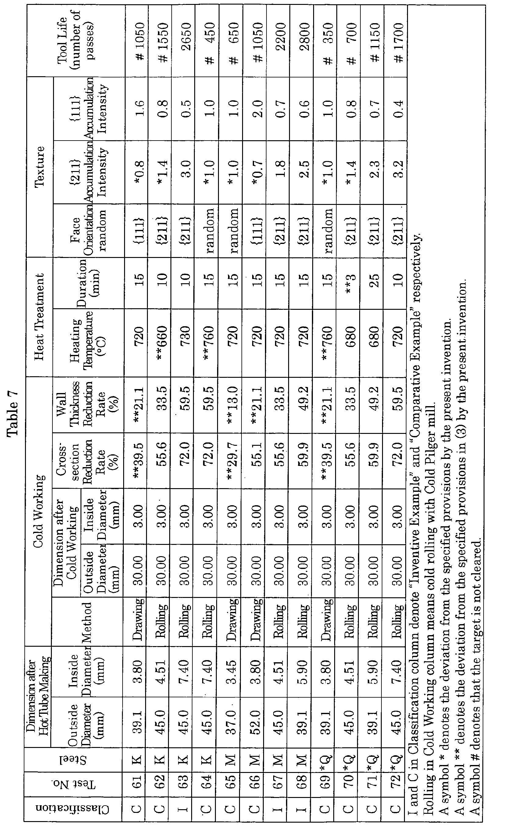
- the heat treatment at 650 - 780°C for 3 - 50 minutes duration by a common method is carried out and the measurement of texture as well as cutting-machining test is performed.
- the texture of steel tube is measured by following procedure. Namely, steel tubes after heat treatment are cut into rings of 20 mm in length, which are successively split into halves on the plane in parallel with longitudinal direction. Then these halves are corrected to prepare flat test specimens (refer to Fig. 1), wherein the plane composing outside surface of steel tube is polished taking off the metal of about 0.5 mm depth to obtain a mirror finished surface, namely "a plane in parallel with the circumferential direction of steel tube", which is subsequently measured by use of an ordinary X-ray diffraction method to obtain each pole figure of (200) and (110), thereby determining face orientation of texture.
- an integrated reflection intensity is measured by afore-mentioned "Specific X-ray Diffraction Method”, and the intensity thus measured is to be divided by the integrated reflection intensity for the same face orientation in case of "Standard Specimen", thereby obtaining an accumulation intensity of the relevant face.
- Standard Specimen denotes the specimen which is made in such a way that a hot forged bar of 60 mm in diameter made from Steel D shown in Table 1 is heated at 1200°C for 30 min followed by cooling in the open air down to the room temperature, heated again at 780°C for 4 hours followed by step cooling comprising first stage cooling down to 660°C with cooling rate of 10°C/hr and an immediate second cooling down to the room temperature in the open air, and then the in-process bar is subjected to cutting and polishing for the cross-section of the round bar to be provided for measurement.
- the steel tubes after heat treatment are subjected to cutting-machining test for measuring the tool life in terms of groove-cutting under the conditions that a chip shown in (i) below is used and machining parameters shown in (ii) below are applied.
- a chip shown in (i) below is used and machining parameters shown in (ii) below are applied.
- the target of the tool life is set to be 2000 passes or more in terms of a number of passes.
- Fig. 2 is a diagram showing a relationship between a tool life and an accumulation intensity of ⁇ 211 ⁇ face in the plane in parallel with the circumferential direction of steel tube.
- Fig. 3 is a diagram showing a relationship between a tool life and an accumulation intensity of ⁇ 111 ⁇ face onto the plane in parallel with the circumferential direction of steel tube.
- the steel tubes after heat treatment are prepared. Namely, the steel tubes of 45.0 mm in diameter by 4.51 mm in thickness after hot tube making, are subjected to afore-mentioned spheroidizing annealing, descaling by acid pickling, and then cold rolling with Cold Pilger mill to obtain the dimension of 30.0 mm in diameter by 3.0 mm in thickness, which are subsequently followed by heat treatment at 700°C for 30 min duration, thus being prepared as the steel tubes for Steels D and H.
- a cutting-machining test for a tool life in terms of groove-cutting onto the outer surface under the same conditions for Example 1, except the change of coating layer onto the "chip" is carried out.
- Table 8 and Fig. 6 show a tool life in machinability test.
- ⁇ 211 ⁇ accumulation intensity and ⁇ 111 ⁇ accumulation intensity denote an accumulation intensity of ⁇ 211 ⁇ face and that of ⁇ 111 ⁇ face respectively.
- the steel with chemical compositions shown in Table 9 is melted and the seamless tubing material for cold working is prepared by Mannesmann process.
- the tubing material thus made is subjected to spheroidizing annealing and then cold working. After cold working, straightening is performed either without heat treatment or subsequent to heat treatment to prepare steel tubes for testing.
- the steel tubes thus obtained are subjected to cutting-machining test to measure a tool life.
- Mannesmann Mandrel mill is utilized to make tubes of 60 mm in diameter by 7.0 mm in thickness, which are subsequently cooled in the open air after hot tube making process.
- the steel tubes thus made are subjected to spheroidizing annealing, subsequent descaling by acid pickling and lubrication treatment by an ordinary method, and then cold drawing with cross-section area reduction rate of 29% to the dimension of 50 mm in diameter by 6.0 mm in thickness.
- the condition of soft annealing comprises the heating temperature at 640°C and holding time of 10 min. and a 2-2-2-1 cross roll type straightening machine is used for straightening.
- Example 1 the steel tubes thus straightened are subjected to cutting-machining test for measuring a tool life in terms of groove-cutting under the conditions that a chip shown in (i) below is used and machining parameters shown in (ii) below are applied.
- the pass when the amount of wear on relief face of the chip reaches no less than 100 ⁇ m or the tip of the chip comes off is sentenced to be the tool life.
- the target of tool life is set to be 2000 passes or more in terms of a number of passes.
- test specimens (10 mm x 2.5 mm) for Charpy Impact test are prepared from the steel tubes after straightening, having 2 mm V notch placed in L direction (longitudinal direction of the tube), and the impact properties at ambient temperature is measured. At the same time, the texture is measured under the same conditions with that for Example 1, which is listed in Table 10 along with above impact properties.
- Steel tubes for bearing element parts according to the present invention wherein the specific compositions are limited and an accumulation intensity of ⁇ 211 ⁇ face along with an impact property at ambient temperature in the longitudinal direction of steel tube are specified, can be provided as a source material for bearing element parts, which have excellent machinability and fatigue life in rolling contact, being incorporated without adding a free-cutting element specifically nor without reducing productivity since the spheroidizing for the same annealing duration with that of conventional spheroidizing treatment can be applied. Accordingly, by applying a manufacturing method or a cutting-machining method according to the present invention, bearing element parts such as races, rollers and shafts can be produced with less cost and efficiently. Thus, the present invention can be widely applied in many fields for use of bearing in various industrial machineries, automobiles and the like.
Landscapes
- Chemical & Material Sciences (AREA)
- Engineering & Computer Science (AREA)
- Materials Engineering (AREA)
- Mechanical Engineering (AREA)
- Metallurgy (AREA)
- Organic Chemistry (AREA)
- Manufacturing & Machinery (AREA)
- Physics & Mathematics (AREA)
- Thermal Sciences (AREA)
- Crystallography & Structural Chemistry (AREA)
- Heat Treatment Of Steel (AREA)
- Heat Treatment Of Articles (AREA)
- Rolling Contact Bearings (AREA)
Abstract
Description
Ti: 0.003% or less
P: 0.02% or less
N: 0.012% or less
O (oxygen): 0.0015% or less


| Classification | Test No. | Steel | Fatigue Life in Rolling Contact (cycles) |
| | 1 | *A | # 4.5 x 10⁶ |
| I | 2 | B | 1.3 x 10⁷ |
| I | 3 | C | 1.9 x 10⁷ |
| I | 4 | D | 3.7 x 10⁷ |
| C | 5 | *E | 2.3 x 10⁷ |
| I | 6 | F | 4.6 x 10⁷ |
| C | 7 | *G | 5.1 x 10⁷ |
| I | 8 | H | 1.2 x 10⁷ |
| C | 9 | *I | 3.2 x 10⁷ |
| C | 10 | *J | 3.5 x 10⁷ |
| I | 11 | K | 4.9 x 10⁷ |
| C | 12 | *L | 6.0 x 10⁷ |
| I | 13 | M | 1.8 x 10⁷ |
| C | 14 | *N | # 8.4 x 10⁶ |
| C | 15 | *O | # 6.3 x 10⁶ |
| C | 16 | *P | 1.9 x 10⁷ |
| C | 17 | *Q | 4.1 x 10⁷ |
| C | 18 | *R | 2.7 x 10⁷ |
| C | 19 | *S | # 7.5 x 10⁶ |
| | 20 | *T | # 5.3 x 10⁶ |
| C and I denote "Comparative Example" and "Inventive Example" respectively. A symbol * denotes the steel whose chemical compositions deviate from the claimed ranges according to the present invention. A symbol # denotes that the target is not cleared. |
| Classification | Test No. | Steel | Presence of Defects in Inside Surface of Steel Tube | Presence of Cracking in Outside and Inside Surfaces | Remaining Scale after Acid Pickling |
| I | 21 | B | No | No | No |
| I | 22 | C | No | No | No |
| I | 23 | D | No | No | No |
| C | 24 | *E | # Yes | No | - |
| I | 25 | F | No | No | No |
| C | 26 | *G | No | No | # Yes |
| I | 27 | H | No | No | No |
| C | 28 | *I | # Yes | No | - |
| C | 29 | *J | # Yes | No | - |
| I | 30 | K | No | No | No |
| C | 31 | *L | No | # Yes | - |
| I | 32 | M | No | No | No |
| C | 33 | *P | # Yes | No | - |
| C | 34 | *Q | No | No | No |
| C | 35 | *R | # Yes | No | - |
| I and C denote "Inventive Example" and "Comparative Example" respectively. " - " in the column of Remaining Scale after Acid Pickling denotes that descaling by acid pickling is not performed. A symbol * denotes the deviation from the claimed ranges of chemical compositions according to the present invention. A symbol # denotes that the target is not cleared. |



| Chemical Compositions (mass %) | Balance; Fe and Impurities | |||||||||
| C | Si | Mn | Cr | Mo | Al | Ti | P | S | N | O |
| 1.00 | 0.23 | 0.33 | 1.38 | 0.03 | 0.022 | 0.0014 | 0.008 | 0.005 | 0.0055 | 0.0007 |
| Test No. | Cold Working | Measurement Result | |||
| Dimension after Cold Working | Heat Treatment after Cold Working | {211} Accumulation Intensity | Impact Value at Ambient Temperature (J/cm2) | Tool Life (number of passes) | |
| 77 | 50 x 6.0 | No | 1.8 | 6 | 3,200 |
| 78 | 50 x 6.0 | Yes | 1.4 | 22 | 1,400 |
Claims (5)
- A steel tube for bearing element parts, characterized by including, in mass %, C: 0.6 - 1.1%, Si: 0.1 - 1.5%, Mn: 0.2 -1.5%, Cr: 0.2 - 2.0%, S: 0.003 - 0.020%, Al: 0.005 - 0.05%, Mo: 0 - 0.5%, and the balance of Fe and impurities that are consisted of Ti: 0.003% or less, P: 0.02% or less, N: 0.012% or less and O (oxygen): 0.0015% or less, wherein the accumulation intensity of {211} face is 1.5 or more in the plane in parallel with the circumferential direction thereof.
- A steel tube for bearing element parts according to claim 1, characterized by including Mo: 0.03 - 0.5 mass%.
- A steel tube for bearing element parts according to above claim 1 or claim 2, characterized in that an impact value in the longitudinal direction thereof at ambient temperature is 10 J/cm2 or less.
- A method of manufacturing said steel tube for bearing element parts according to above claim 1 or claim 3, characterized by containing the steps of
spheroidizing annealing after hot rolling process;
successive cold working in such a way that the cross-section area reduction rate of steel tube is in the range of 50 - 80% and the wall thickness reduction rate thereof is in the range of 30 - 50%; and
heat treating where heating temperature is in the range of 680°C and A1 point and the duration is 5 - 40 minutes.
Here, A1 point designates the value expressed by the formula as below, where the symbol of the metal element in it means the content, mass %, in the steel. - A method of machining the steel tube for bearing element parts according to any one of claims 1 - 3, characterized in that a cemented carbide chip with a coating layer having 3000 or more in Vicker's Hardness is applied.
Applications Claiming Priority (3)
| Application Number | Priority Date | Filing Date | Title |
|---|---|---|---|
| JP2003022111 | 2003-01-30 | ||
| JP2003022111 | 2003-01-30 | ||
| PCT/JP2004/000786 WO2004067790A1 (en) | 2003-01-30 | 2004-01-28 | Steel pipe for bearing elements, and methods for producing and cutting the same |
Publications (3)
| Publication Number | Publication Date |
|---|---|
| EP1595966A1 true EP1595966A1 (en) | 2005-11-16 |
| EP1595966A4 EP1595966A4 (en) | 2006-06-14 |
| EP1595966B1 EP1595966B1 (en) | 2012-02-22 |
Family
ID=32820681
Family Applications (1)
| Application Number | Title | Priority Date | Filing Date |
|---|---|---|---|
| EP04705918A Expired - Lifetime EP1595966B1 (en) | 2003-01-30 | 2004-01-28 | Steel pipe for bearing elements, and methods for producing and cutting the same |
Country Status (7)
| Country | Link |
|---|---|
| US (1) | US7393420B2 (en) |
| EP (1) | EP1595966B1 (en) |
| JP (1) | JP4274177B2 (en) |
| CN (1) | CN100344784C (en) |
| AT (1) | ATE546557T1 (en) |
| BR (1) | BRPI0406697B1 (en) |
| WO (1) | WO2004067790A1 (en) |
Cited By (8)
| Publication number | Priority date | Publication date | Assignee | Title |
|---|---|---|---|---|
| FR2935988A1 (en) * | 2008-09-12 | 2010-03-19 | Ascometal Sa | Steel composition, useful in steel roll, comprises carbon, silicon, manganese, chromium, nickel, molybdenum, sulfur, phosphorus, aluminum, nitrogen, niobium, and titanium, optionally bismuth, lead, tellurium, selenium and/or calcium |
| EP2159294A4 (en) * | 2007-06-28 | 2012-04-04 | Kobe Steel Ltd | Steel for mechanical structure excelling in machinability and process for producing the same |
| EP2647734A4 (en) * | 2010-11-29 | 2014-04-30 | Jfe Steel Corp | ROLLER STEEL HAVING EXCELLENT MACHINING CAPABILITY AFTER SPHERERIZATION RESTRAINT AND EXCELLENT FATIGUE RESISTANCE DUE TO HYDROGEN AFTER TEMPERING / REVENUE |
| EP1826286A3 (en) * | 2006-02-28 | 2014-12-24 | JFE Steel Corporation | Steel part having long rolling contact fatigue life and method for producing the same |
| US9034120B2 (en) | 2010-11-29 | 2015-05-19 | Jfe Steel Corporation | Bearing steel being excellent both in workability after spheroidizing-annealing and in hydrogen fatigue resistance property after quenching and tempering |
| EP2617848A4 (en) * | 2010-09-15 | 2015-07-01 | Kobe Steel Ltd | Bearing steel |
| EP2832893A4 (en) * | 2012-03-30 | 2015-09-02 | Kobe Steel Ltd | Bearing steel material having superior rolling fatigue characteristics and a method for producing same |
| EP2832892A4 (en) * | 2012-03-30 | 2015-09-02 | Kobe Steel Ltd | STEEL FOR BEARINGS HAVING SUPERIOR COLD MACHINABILITY AND PRODUCTION METHOD THEREFOR |
Families Citing this family (15)
| Publication number | Priority date | Publication date | Assignee | Title |
|---|---|---|---|---|
| CA2514493C (en) * | 2004-09-17 | 2013-01-29 | Sulzer Metco Ag | A spray powder |
| CN103547696A (en) * | 2011-05-17 | 2014-01-29 | Skf公司 | Improved bearing steel |
| CN102352466B (en) * | 2011-11-02 | 2013-07-24 | 承德建龙特殊钢有限公司 | High-carbon chromium bearing steel GCr15 and production method thereof |
| DE102013104806A1 (en) * | 2013-05-08 | 2014-11-13 | Sandvik Materials Technology Deutschland Gmbh | belt furnace |
| CN104451452B (en) * | 2013-09-13 | 2016-09-28 | 宝钢特钢有限公司 | A kind of bearing steel for wind power equipment and preparation method thereof |
| CN103484758A (en) * | 2013-09-29 | 2014-01-01 | 苏州市凯业金属制品有限公司 | Easily-welded metal pipe |
| CN104073724B (en) * | 2014-06-30 | 2016-02-03 | 北京科技大学 | A kind of preparation method of rod mill rod iron |
| CN104294156B (en) * | 2014-09-05 | 2016-06-08 | 武汉钢铁(集团)公司 | A kind of economy the excellent high-carbon wear-resistant steel pipe of processing characteristics and production method |
| GB2532761A (en) * | 2014-11-27 | 2016-06-01 | Skf Ab | Bearing steel |
| CN105568134A (en) * | 2016-01-05 | 2016-05-11 | 江阴兴澄特种钢铁有限公司 | Steel for carbon hub bearing of microalloying car and production method thereof |
| CN108929997B (en) * | 2017-05-26 | 2021-08-17 | 宝山钢铁股份有限公司 | A kind of bearing steel for automobile wheel hub and its manufacturing method |
| CN107130181A (en) * | 2017-06-22 | 2017-09-05 | 合肥力和机械有限公司 | A kind of household electrical appliances special bearing steel ball and preparation method thereof |
| WO2019171624A1 (en) * | 2018-03-09 | 2019-09-12 | 日新製鋼株式会社 | Steel pipe and production method for steel pipe |
| CN113423516B (en) * | 2019-02-13 | 2023-06-02 | 日本制铁株式会社 | Steel pipe for fuel injection pipe and fuel injection pipe using same |
| CN111763889A (en) * | 2020-06-02 | 2020-10-13 | 钢铁研究总院 | A kind of high carbon bearing steel and preparation method thereof |
Family Cites Families (9)
| Publication number | Priority date | Publication date | Assignee | Title |
|---|---|---|---|---|
| JPH01255651A (en) | 1988-04-04 | 1989-10-12 | Kawasaki Steel Corp | High si-low cr bearing steel excellent in machinability |
| JPH0356641A (en) | 1989-07-26 | 1991-03-12 | Daido Steel Co Ltd | Bearing steel having superior machinability |
| JP3245045B2 (en) | 1996-02-22 | 2002-01-07 | 山陽特殊製鋼株式会社 | Bearing steel excellent in machinability and cold workability and its annealing method |
| JP3340927B2 (en) * | 1996-12-19 | 2002-11-05 | 山陽特殊製鋼株式会社 | Steel tube for medium carbon bearings having both machinability and cold forgeability, and method of manufacturing the same |
| FR2761699B1 (en) * | 1997-04-04 | 1999-05-14 | Ascometal Sa | STEEL AND METHOD FOR MANUFACTURING A BEARING PART |
| JP3405277B2 (en) * | 1999-08-03 | 2003-05-12 | 住友金属工業株式会社 | Steel wire rod, steel bar and steel pipe for bearing element parts with excellent machinability |
| SE9903089D0 (en) * | 1999-09-01 | 1999-09-01 | Sandvik Ab | Coated grooving or parting insert |
| JP3463651B2 (en) * | 2000-04-18 | 2003-11-05 | 住友金属工業株式会社 | Bearing steel |
| JP3614113B2 (en) * | 2001-03-16 | 2005-01-26 | 住友金属工業株式会社 | Steel material for bearing element parts with excellent machinability |
-
2004
- 2004-01-28 BR BRPI0406697A patent/BRPI0406697B1/en active IP Right Grant
- 2004-01-28 EP EP04705918A patent/EP1595966B1/en not_active Expired - Lifetime
- 2004-01-28 AT AT04705918T patent/ATE546557T1/en active
- 2004-01-28 CN CNB200480003332XA patent/CN100344784C/en not_active Expired - Lifetime
- 2004-01-28 JP JP2005504734A patent/JP4274177B2/en not_active Expired - Fee Related
- 2004-01-28 WO PCT/JP2004/000786 patent/WO2004067790A1/en not_active Ceased
-
2005
- 2005-07-29 US US11/191,914 patent/US7393420B2/en not_active Expired - Lifetime
Cited By (10)
| Publication number | Priority date | Publication date | Assignee | Title |
|---|---|---|---|---|
| EP1826286A3 (en) * | 2006-02-28 | 2014-12-24 | JFE Steel Corporation | Steel part having long rolling contact fatigue life and method for producing the same |
| EP2159294A4 (en) * | 2007-06-28 | 2012-04-04 | Kobe Steel Ltd | Steel for mechanical structure excelling in machinability and process for producing the same |
| FR2935988A1 (en) * | 2008-09-12 | 2010-03-19 | Ascometal Sa | Steel composition, useful in steel roll, comprises carbon, silicon, manganese, chromium, nickel, molybdenum, sulfur, phosphorus, aluminum, nitrogen, niobium, and titanium, optionally bismuth, lead, tellurium, selenium and/or calcium |
| EP2208804A1 (en) * | 2008-09-12 | 2010-07-21 | Ascometal | Steel, in particular for bearings and mechanical elements suitable for carburisation or carbonitridation, and parts made using this steel |
| EP2617848A4 (en) * | 2010-09-15 | 2015-07-01 | Kobe Steel Ltd | Bearing steel |
| EP2647734A4 (en) * | 2010-11-29 | 2014-04-30 | Jfe Steel Corp | ROLLER STEEL HAVING EXCELLENT MACHINING CAPABILITY AFTER SPHERERIZATION RESTRAINT AND EXCELLENT FATIGUE RESISTANCE DUE TO HYDROGEN AFTER TEMPERING / REVENUE |
| US8894779B2 (en) | 2010-11-29 | 2014-11-25 | Jfe Steel Corporation | Bearing steel being excellent both in post spheroidizing-annealing workability and in post quenching-tempering hydrogen fatigue resistance property |
| US9034120B2 (en) | 2010-11-29 | 2015-05-19 | Jfe Steel Corporation | Bearing steel being excellent both in workability after spheroidizing-annealing and in hydrogen fatigue resistance property after quenching and tempering |
| EP2832893A4 (en) * | 2012-03-30 | 2015-09-02 | Kobe Steel Ltd | Bearing steel material having superior rolling fatigue characteristics and a method for producing same |
| EP2832892A4 (en) * | 2012-03-30 | 2015-09-02 | Kobe Steel Ltd | STEEL FOR BEARINGS HAVING SUPERIOR COLD MACHINABILITY AND PRODUCTION METHOD THEREFOR |
Also Published As
| Publication number | Publication date |
|---|---|
| BRPI0406697B1 (en) | 2016-06-14 |
| US20050279431A1 (en) | 2005-12-22 |
| CN100344784C (en) | 2007-10-24 |
| ATE546557T1 (en) | 2012-03-15 |
| EP1595966A4 (en) | 2006-06-14 |
| JPWO2004067790A1 (en) | 2006-05-18 |
| EP1595966B1 (en) | 2012-02-22 |
| JP4274177B2 (en) | 2009-06-03 |
| CN1745188A (en) | 2006-03-08 |
| BRPI0406697A (en) | 2005-12-20 |
| US7393420B2 (en) | 2008-07-01 |
| WO2004067790A1 (en) | 2004-08-12 |
Similar Documents
| Publication | Publication Date | Title |
|---|---|---|
| US7393420B2 (en) | Steel tube for bearing element parts and method of manufacturing as well as machining the same | |
| JP4751224B2 (en) | High strength seamless steel pipe for machine structure with excellent toughness and weldability and method for producing the same | |
| JP5655986B2 (en) | Steel wire rod or bar | |
| KR101369113B1 (en) | Steel for machine structural use, manufacturing method for same, case hardened steel components, and manufacturing method for same | |
| EP2135962A1 (en) | Case-hardened steel pipe excellent in workability and process for production thereof | |
| EP2204463A1 (en) | Martensitic non-heat-treated steel for hot forging and non-heat-treated steel hot forgings | |
| US20040099355A1 (en) | Method of producing high-carbon steel pipe having superior cold workability and induction hardenability | |
| JP6652019B2 (en) | Machine structural steel and induction hardened steel parts for induction hardening | |
| JP7555080B2 (en) | Manufacturing method of cold rolled steel sheet and manufacturing method of steel parts | |
| JP3405277B2 (en) | Steel wire rod, steel bar and steel pipe for bearing element parts with excellent machinability | |
| US20140363329A1 (en) | Rolled steel bar or wire rod for hot forging | |
| CN111742076B (en) | High carbon cold rolled steel sheet and method for manufacturing same | |
| JP2002275584A (en) | Steel material for bearing element parts with excellent machinability | |
| JP2012177154A (en) | High-carbon steel pipe excellent in cold workability, machinability and hardenability, and method for producing the same | |
| JP5472063B2 (en) | Free-cutting steel for cold forging | |
| JP4500246B2 (en) | Steel pipe for machine structural member and manufacturing method thereof | |
| JP7417058B2 (en) | Induction hardened ropes and induction hardened parts | |
| JP7626165B2 (en) | Manufacturing method for steel parts | |
| JP5020689B2 (en) | Machine structure steel pipe with excellent machinability | |
| EP1001043B1 (en) | Martensitic stainless steel parts and method for producing the same | |
| JP7469596B2 (en) | Bearing Steel | |
| JP7417059B2 (en) | Induction hardened nitrided steel and induction hardened nitrided parts | |
| JP3913088B2 (en) | Manufacturing method for medium and high carbon steel sheets with excellent deep drawability | |
| JP7748018B2 (en) | steel plate | |
| JP7323850B2 (en) | Steel and carburized steel parts |
Legal Events
| Date | Code | Title | Description |
|---|---|---|---|
| PUAI | Public reference made under article 153(3) epc to a published international application that has entered the european phase |
Free format text: ORIGINAL CODE: 0009012 |
|
| 17P | Request for examination filed |
Effective date: 20050817 |
|
| AK | Designated contracting states |
Kind code of ref document: A1 Designated state(s): AT BE BG CH CY CZ DE DK EE ES FI FR GB GR HU IE IT LI LU MC NL PT RO SE SI SK TR |
|
| AX | Request for extension of the european patent |
Extension state: AL LT LV MK |
|
| DAX | Request for extension of the european patent (deleted) | ||
| A4 | Supplementary search report drawn up and despatched |
Effective date: 20060424 |
|
| 17Q | First examination report despatched |
Effective date: 20080723 |
|
| GRAP | Despatch of communication of intention to grant a patent |
Free format text: ORIGINAL CODE: EPIDOSNIGR1 |
|
| GRAS | Grant fee paid |
Free format text: ORIGINAL CODE: EPIDOSNIGR3 |
|
| GRAA | (expected) grant |
Free format text: ORIGINAL CODE: 0009210 |
|
| AK | Designated contracting states |
Kind code of ref document: B1 Designated state(s): AT BE BG CH CY CZ DE DK EE ES FI FR GB GR HU IE IT LI LU MC NL PT RO SE SI SK TR |
|
| REG | Reference to a national code |
Ref country code: GB Ref legal event code: FG4D |
|
| REG | Reference to a national code |
Ref country code: CH Ref legal event code: EP |
|
| REG | Reference to a national code |
Ref country code: AT Ref legal event code: REF Ref document number: 546557 Country of ref document: AT Kind code of ref document: T Effective date: 20120315 |
|
| REG | Reference to a national code |
Ref country code: IE Ref legal event code: FG4D |
|
| REG | Reference to a national code |
Ref country code: SE Ref legal event code: TRGR |
|
| REG | Reference to a national code |
Ref country code: DE Ref legal event code: R096 Ref document number: 602004036586 Country of ref document: DE Effective date: 20120419 |
|
| REG | Reference to a national code |
Ref country code: NL Ref legal event code: VDEP Effective date: 20120222 |
|
| PG25 | Lapsed in a contracting state [announced via postgrant information from national office to epo] |
Ref country code: NL Free format text: LAPSE BECAUSE OF FAILURE TO SUBMIT A TRANSLATION OF THE DESCRIPTION OR TO PAY THE FEE WITHIN THE PRESCRIBED TIME-LIMIT Effective date: 20120222 |
|
| PG25 | Lapsed in a contracting state [announced via postgrant information from national office to epo] |
Ref country code: GR Free format text: LAPSE BECAUSE OF FAILURE TO SUBMIT A TRANSLATION OF THE DESCRIPTION OR TO PAY THE FEE WITHIN THE PRESCRIBED TIME-LIMIT Effective date: 20120523 Ref country code: FI Free format text: LAPSE BECAUSE OF FAILURE TO SUBMIT A TRANSLATION OF THE DESCRIPTION OR TO PAY THE FEE WITHIN THE PRESCRIBED TIME-LIMIT Effective date: 20120222 Ref country code: BE Free format text: LAPSE BECAUSE OF FAILURE TO SUBMIT A TRANSLATION OF THE DESCRIPTION OR TO PAY THE FEE WITHIN THE PRESCRIBED TIME-LIMIT Effective date: 20120222 Ref country code: PT Free format text: LAPSE BECAUSE OF FAILURE TO SUBMIT A TRANSLATION OF THE DESCRIPTION OR TO PAY THE FEE WITHIN THE PRESCRIBED TIME-LIMIT Effective date: 20120622 |
|
| REG | Reference to a national code |
Ref country code: AT Ref legal event code: MK05 Ref document number: 546557 Country of ref document: AT Kind code of ref document: T Effective date: 20120222 |
|
| PG25 | Lapsed in a contracting state [announced via postgrant information from national office to epo] |
Ref country code: CY Free format text: LAPSE BECAUSE OF FAILURE TO SUBMIT A TRANSLATION OF THE DESCRIPTION OR TO PAY THE FEE WITHIN THE PRESCRIBED TIME-LIMIT Effective date: 20120222 |
|
| PG25 | Lapsed in a contracting state [announced via postgrant information from national office to epo] |
Ref country code: CZ Free format text: LAPSE BECAUSE OF FAILURE TO SUBMIT A TRANSLATION OF THE DESCRIPTION OR TO PAY THE FEE WITHIN THE PRESCRIBED TIME-LIMIT Effective date: 20120222 Ref country code: DK Free format text: LAPSE BECAUSE OF FAILURE TO SUBMIT A TRANSLATION OF THE DESCRIPTION OR TO PAY THE FEE WITHIN THE PRESCRIBED TIME-LIMIT Effective date: 20120222 Ref country code: SI Free format text: LAPSE BECAUSE OF FAILURE TO SUBMIT A TRANSLATION OF THE DESCRIPTION OR TO PAY THE FEE WITHIN THE PRESCRIBED TIME-LIMIT Effective date: 20120222 Ref country code: RO Free format text: LAPSE BECAUSE OF FAILURE TO SUBMIT A TRANSLATION OF THE DESCRIPTION OR TO PAY THE FEE WITHIN THE PRESCRIBED TIME-LIMIT Effective date: 20120222 Ref country code: EE Free format text: LAPSE BECAUSE OF FAILURE TO SUBMIT A TRANSLATION OF THE DESCRIPTION OR TO PAY THE FEE WITHIN THE PRESCRIBED TIME-LIMIT Effective date: 20120222 |
|
| PG25 | Lapsed in a contracting state [announced via postgrant information from national office to epo] |
Ref country code: SK Free format text: LAPSE BECAUSE OF FAILURE TO SUBMIT A TRANSLATION OF THE DESCRIPTION OR TO PAY THE FEE WITHIN THE PRESCRIBED TIME-LIMIT Effective date: 20120222 |
|
| PLBE | No opposition filed within time limit |
Free format text: ORIGINAL CODE: 0009261 |
|
| STAA | Information on the status of an ep patent application or granted ep patent |
Free format text: STATUS: NO OPPOSITION FILED WITHIN TIME LIMIT |
|
| RAP2 | Party data changed (patent owner data changed or rights of a patent transferred) |
Owner name: NIPPON STEEL & SUMITOMO METAL CORPORATION |
|
| 26N | No opposition filed |
Effective date: 20121123 |
|
| PG25 | Lapsed in a contracting state [announced via postgrant information from national office to epo] |
Ref country code: AT Free format text: LAPSE BECAUSE OF FAILURE TO SUBMIT A TRANSLATION OF THE DESCRIPTION OR TO PAY THE FEE WITHIN THE PRESCRIBED TIME-LIMIT Effective date: 20120222 |
|
| REG | Reference to a national code |
Ref country code: DE Ref legal event code: R097 Ref document number: 602004036586 Country of ref document: DE Effective date: 20121123 |
|
| PG25 | Lapsed in a contracting state [announced via postgrant information from national office to epo] |
Ref country code: ES Free format text: LAPSE BECAUSE OF FAILURE TO SUBMIT A TRANSLATION OF THE DESCRIPTION OR TO PAY THE FEE WITHIN THE PRESCRIBED TIME-LIMIT Effective date: 20120602 |
|
| PG25 | Lapsed in a contracting state [announced via postgrant information from national office to epo] |
Ref country code: BG Free format text: LAPSE BECAUSE OF FAILURE TO SUBMIT A TRANSLATION OF THE DESCRIPTION OR TO PAY THE FEE WITHIN THE PRESCRIBED TIME-LIMIT Effective date: 20120522 |
|
| PG25 | Lapsed in a contracting state [announced via postgrant information from national office to epo] |
Ref country code: MC Free format text: LAPSE BECAUSE OF NON-PAYMENT OF DUE FEES Effective date: 20130131 |
|
| REG | Reference to a national code |
Ref country code: CH Ref legal event code: PL |
|
| REG | Reference to a national code |
Ref country code: IE Ref legal event code: MM4A |
|
| PG25 | Lapsed in a contracting state [announced via postgrant information from national office to epo] |
Ref country code: CH Free format text: LAPSE BECAUSE OF NON-PAYMENT OF DUE FEES Effective date: 20130131 Ref country code: LI Free format text: LAPSE BECAUSE OF NON-PAYMENT OF DUE FEES Effective date: 20130131 |
|
| REG | Reference to a national code |
Ref country code: GB Ref legal event code: 732E Free format text: REGISTERED BETWEEN 20131010 AND 20131016 |
|
| PG25 | Lapsed in a contracting state [announced via postgrant information from national office to epo] |
Ref country code: IE Free format text: LAPSE BECAUSE OF NON-PAYMENT OF DUE FEES Effective date: 20130128 |
|
| REG | Reference to a national code |
Ref country code: DE Ref legal event code: R082 Ref document number: 602004036586 Country of ref document: DE Representative=s name: RECHTS- UND PATENTANWAELTE LORENZ SEIDLER GOSS, DE |
|
| REG | Reference to a national code |
Ref country code: DE Ref legal event code: R082 Ref document number: 602004036586 Country of ref document: DE Representative=s name: LORENZ SEIDLER GOSSEL RECHTSANWAELTE PATENTANW, DE Effective date: 20140402 Ref country code: DE Ref legal event code: R082 Ref document number: 602004036586 Country of ref document: DE Representative=s name: RECHTS- UND PATENTANWAELTE LORENZ SEIDLER GOSS, DE Effective date: 20140402 Ref country code: DE Ref legal event code: R081 Ref document number: 602004036586 Country of ref document: DE Owner name: NIPPON STEEL & SUMITOMO METAL CORPORATION, JP Free format text: FORMER OWNER: SUMITOMO METAL INDUSTRIES, LTD., OSAKA, JP Effective date: 20140402 Ref country code: DE Ref legal event code: R081 Ref document number: 602004036586 Country of ref document: DE Owner name: NIPPON STEEL & SUMITOMO METAL CORPORATION, JP Free format text: FORMER OWNER: SUMITOMO METAL INDUSTRIES, LTD., OSAKA, JP Effective date: 20120227 |
|
| PG25 | Lapsed in a contracting state [announced via postgrant information from national office to epo] |
Ref country code: TR Free format text: LAPSE BECAUSE OF FAILURE TO SUBMIT A TRANSLATION OF THE DESCRIPTION OR TO PAY THE FEE WITHIN THE PRESCRIBED TIME-LIMIT Effective date: 20120222 |
|
| PG25 | Lapsed in a contracting state [announced via postgrant information from national office to epo] |
Ref country code: LU Free format text: LAPSE BECAUSE OF NON-PAYMENT OF DUE FEES Effective date: 20130128 Ref country code: HU Free format text: LAPSE BECAUSE OF FAILURE TO SUBMIT A TRANSLATION OF THE DESCRIPTION OR TO PAY THE FEE WITHIN THE PRESCRIBED TIME-LIMIT; INVALID AB INITIO Effective date: 20040128 |
|
| REG | Reference to a national code |
Ref country code: FR Ref legal event code: PLFP Year of fee payment: 13 |
|
| REG | Reference to a national code |
Ref country code: FR Ref legal event code: PLFP Year of fee payment: 14 |
|
| REG | Reference to a national code |
Ref country code: FR Ref legal event code: PLFP Year of fee payment: 15 |
|
| REG | Reference to a national code |
Ref country code: DE Ref legal event code: R082 Ref document number: 602004036586 Country of ref document: DE Representative=s name: LORENZ SEIDLER GOSSEL RECHTSANWAELTE PATENTANW, DE Ref country code: DE Ref legal event code: R081 Ref document number: 602004036586 Country of ref document: DE Owner name: NIPPON STEEL CORP., JP Free format text: FORMER OWNER: NIPPON STEEL & SUMITOMO METAL CORPORATION, TOKYO, JP |
|
| PGFP | Annual fee paid to national office [announced via postgrant information from national office to epo] |
Ref country code: SE Payment date: 20221212 Year of fee payment: 20 Ref country code: GB Payment date: 20221208 Year of fee payment: 20 Ref country code: FR Payment date: 20221208 Year of fee payment: 20 |
|
| PGFP | Annual fee paid to national office [announced via postgrant information from national office to epo] |
Ref country code: IT Payment date: 20221213 Year of fee payment: 20 Ref country code: DE Payment date: 20221207 Year of fee payment: 20 |
|
| REG | Reference to a national code |
Ref country code: DE Ref legal event code: R071 Ref document number: 602004036586 Country of ref document: DE |
|
| REG | Reference to a national code |
Ref country code: GB Ref legal event code: PE20 Expiry date: 20240127 |
|
| REG | Reference to a national code |
Ref country code: SE Ref legal event code: EUG |
|
| PG25 | Lapsed in a contracting state [announced via postgrant information from national office to epo] |
Ref country code: GB Free format text: LAPSE BECAUSE OF EXPIRATION OF PROTECTION Effective date: 20240127 |