EP1595404B1 - Bilddecodierungsverfahren - Google Patents
Bilddecodierungsverfahren Download PDFInfo
- Publication number
- EP1595404B1 EP1595404B1 EP04711623.1A EP04711623A EP1595404B1 EP 1595404 B1 EP1595404 B1 EP 1595404B1 EP 04711623 A EP04711623 A EP 04711623A EP 1595404 B1 EP1595404 B1 EP 1595404B1
- Authority
- EP
- European Patent Office
- Prior art keywords
- transmission unit
- transmission
- decoding order
- picture
- packet
- Prior art date
- Legal status (The legal status is an assumption and is not a legal conclusion. Google has not performed a legal analysis and makes no representation as to the accuracy of the status listed.)
- Expired - Lifetime
Links
Images


Classifications
-
- H—ELECTRICITY
- H04—ELECTRIC COMMUNICATION TECHNIQUE
- H04N—PICTORIAL COMMUNICATION, e.g. TELEVISION
- H04N21/00—Selective content distribution, e.g. interactive television or video on demand [VOD]
- H04N21/60—Network structure or processes for video distribution between server and client or between remote clients; Control signalling between clients, server and network components; Transmission of management data between server and client, e.g. sending from server to client commands for recording incoming content stream; Communication details between server and client
- H04N21/63—Control signaling related to video distribution between client, server and network components; Network processes for video distribution between server and clients or between remote clients, e.g. transmitting basic layer and enhancement layers over different transmission paths, setting up a peer-to-peer communication via Internet between remote STB's; Communication protocols; Addressing
- H04N21/647—Control signaling between network components and server or clients; Network processes for video distribution between server and clients, e.g. controlling the quality of the video stream, by dropping packets, protecting content from unauthorised alteration within the network, monitoring of network load, bridging between two different networks, e.g. between IP and wireless
- H04N21/64784—Data processing by the network
- H04N21/64792—Controlling the complexity of the content stream, e.g. by dropping packets
-
- H—ELECTRICITY
- H04—ELECTRIC COMMUNICATION TECHNIQUE
- H04N—PICTORIAL COMMUNICATION, e.g. TELEVISION
- H04N19/00—Methods or arrangements for coding, decoding, compressing or decompressing digital video signals
- H04N19/10—Methods or arrangements for coding, decoding, compressing or decompressing digital video signals using adaptive coding
- H04N19/102—Methods or arrangements for coding, decoding, compressing or decompressing digital video signals using adaptive coding characterised by the element, parameter or selection affected or controlled by the adaptive coding
- H04N19/132—Sampling, masking or truncation of coding units, e.g. adaptive resampling, frame skipping, frame interpolation or high-frequency transform coefficient masking
-
- H—ELECTRICITY
- H04—ELECTRIC COMMUNICATION TECHNIQUE
- H04N—PICTORIAL COMMUNICATION, e.g. TELEVISION
- H04N19/00—Methods or arrangements for coding, decoding, compressing or decompressing digital video signals
- H04N19/10—Methods or arrangements for coding, decoding, compressing or decompressing digital video signals using adaptive coding
- H04N19/169—Methods or arrangements for coding, decoding, compressing or decompressing digital video signals using adaptive coding characterised by the coding unit, i.e. the structural portion or semantic portion of the video signal being the object or the subject of the adaptive coding
- H04N19/17—Methods or arrangements for coding, decoding, compressing or decompressing digital video signals using adaptive coding characterised by the coding unit, i.e. the structural portion or semantic portion of the video signal being the object or the subject of the adaptive coding the unit being an image region, e.g. an object
- H04N19/172—Methods or arrangements for coding, decoding, compressing or decompressing digital video signals using adaptive coding characterised by the coding unit, i.e. the structural portion or semantic portion of the video signal being the object or the subject of the adaptive coding the unit being an image region, e.g. an object the region being a picture, frame or field
-
- H—ELECTRICITY
- H04—ELECTRIC COMMUNICATION TECHNIQUE
- H04N—PICTORIAL COMMUNICATION, e.g. TELEVISION
- H04N19/00—Methods or arrangements for coding, decoding, compressing or decompressing digital video signals
- H04N19/30—Methods or arrangements for coding, decoding, compressing or decompressing digital video signals using hierarchical techniques, e.g. scalability
- H04N19/31—Methods or arrangements for coding, decoding, compressing or decompressing digital video signals using hierarchical techniques, e.g. scalability in the temporal domain
-
- H—ELECTRICITY
- H04—ELECTRIC COMMUNICATION TECHNIQUE
- H04N—PICTORIAL COMMUNICATION, e.g. TELEVISION
- H04N19/00—Methods or arrangements for coding, decoding, compressing or decompressing digital video signals
- H04N19/44—Decoders specially adapted therefor, e.g. video decoders which are asymmetric with respect to the encoder
-
- H—ELECTRICITY
- H04—ELECTRIC COMMUNICATION TECHNIQUE
- H04N—PICTORIAL COMMUNICATION, e.g. TELEVISION
- H04N19/00—Methods or arrangements for coding, decoding, compressing or decompressing digital video signals
- H04N19/50—Methods or arrangements for coding, decoding, compressing or decompressing digital video signals using predictive coding
- H04N19/587—Methods or arrangements for coding, decoding, compressing or decompressing digital video signals using predictive coding involving temporal sub-sampling or interpolation, e.g. decimation or subsequent interpolation of pictures in a video sequence
-
- H—ELECTRICITY
- H04—ELECTRIC COMMUNICATION TECHNIQUE
- H04N—PICTORIAL COMMUNICATION, e.g. TELEVISION
- H04N19/00—Methods or arrangements for coding, decoding, compressing or decompressing digital video signals
- H04N19/60—Methods or arrangements for coding, decoding, compressing or decompressing digital video signals using transform coding
- H04N19/61—Methods or arrangements for coding, decoding, compressing or decompressing digital video signals using transform coding in combination with predictive coding
-
- H—ELECTRICITY
- H04—ELECTRIC COMMUNICATION TECHNIQUE
- H04N—PICTORIAL COMMUNICATION, e.g. TELEVISION
- H04N21/00—Selective content distribution, e.g. interactive television or video on demand [VOD]
- H04N21/60—Network structure or processes for video distribution between server and client or between remote clients; Control signalling between clients, server and network components; Transmission of management data between server and client, e.g. sending from server to client commands for recording incoming content stream; Communication details between server and client
- H04N21/63—Control signaling related to video distribution between client, server and network components; Network processes for video distribution between server and clients or between remote clients, e.g. transmitting basic layer and enhancement layers over different transmission paths, setting up a peer-to-peer communication via Internet between remote STB's; Communication protocols; Addressing
- H04N21/643—Communication protocols
- H04N21/6437—Real-time Transport Protocol [RTP]
Definitions
- the present invention relates to a method for ordering encoded pictures.
- the invention also relates to a system, an encoder, a decoder, a device, a signal and a computer program product.
- Published video coding standards include ITU-T H.261, ITU-T H.263, ISO/IEC MPEG-1, ISO/IEC MPEG-2, and ISO/IEC MPEG-4 Part 2. These standards are herein referred to as conventional video coding standards.
- the European patent application EP1069777 describes a system for video coding where time stamps are added to the packetized elementary stream (PES) header data in order to reduce delays in packetizing.
- PES packetized elementary stream
- Video communication systems can be divided into conversational and non-conversational systems.
- Conversational systems include video conferencing and video telephony. Examples of such systems include ITU-T Recommendations H.320, H.323, and H.324 that specify a video conferencing/telephony system operating in ISDN, IP, and PSTN networks respectively.
- Conversational systems are characterized by the intent to minimize the end-to-end delay (from audio-video capture to the far-end audio-video presentation) in order to improve the user experience.
- Non-conversational systems include playback of stored content, such as Digital Versatile Disks (DVDs) or video files stored in a mass memory of a playback device, digital TV, and streaming.
- DVDs Digital Versatile Disks
- video files stored in a mass memory of a playback device, digital TV, and streaming.
- MPEG-2 A dominant standard in digital video consumer electronics today is MPEG-2, which includes specifications for video compression, audio compression, storage, and transport.
- the storage and transport of coded video is based on the concept of an elementary stream.
- An elementary stream consists of coded data from a single source (e.g. video) plus ancillary data needed for synchronization, identification and characterization of the source information.
- An elementary stream is packetized into either constant-length or variable-length packets to form a Packetized Elementary Stream (PES).
- PES Packetized Elementary Stream
- Each PES packet consists of a header followed by stream data called the payload.
- PES packets from various elementary streams are combined to form either a Program Stream (PS) or a Transport Stream (TS).
- PS Program Stream
- TS Transport Stream
- PS is aimed at applications having negligible transmission errors, such as store-and-play type of applications.
- TS is aimed at applications that are susceptible of transmission errors.
- TS
- JVT Joint Video Team
- H.26L An earlier standardization project in ITU-T
- H.26L An earlier standardization project in ITU-T
- the goal of the JVT standardization is to release the same standard text as ITU-T Recommendation H.264 and ISO/IEC International Standard 14496-10 (MPEG-4 Part 10).
- the draft standard is referred to as the JVT coding standard in this paper, and the codec according to the draft standard is referred to as the JVT codec.
- the codec specification itself distinguishes conceptually between a video coding layer (VCL), and a network abstraction layer (NAL).
- VCL contains the signal processing functionality of the codec, things such as transform, quantization, motion search/compensation, and the loop filter. It follows the general concept of most of today's video codecs, a macroblock-based coder that utilizes inter picture prediction with motion compensation, and transform coding of the residual signal.
- the output of the VCL encoder are slices: a bit string that contains the macroblock data of an integer number of macroblocks, and the information of the slice header (containing the spatial address of the first macroblock in the slice, the initial quantization parameter, and similar).
- Macroblocks in slices are ordered consecutively in scan order unless a different macroblock allocation is specified, using the so-called Flexible Macroblock Ordering syntax.
- In-picture prediction such as intra prediction and motion vector prediction, is used only within a slice.
- NAL Network Abstraction Layer Units
- NALUs Network Abstraction Layer Units
- JVT's Annex B defines an encapsulation process to transmit such NALUs over byte-stream oriented networks.
- the optional reference picture selection mode of H.263 and the NEWPRED coding tool of MPEG-4 Part 2 enable selection of the reference frame for motion compensation per each picture segment, e.g., per each slice in H.263. Furthermore, the optional Enhanced Reference Picture Selection mode of H.263 and the JVT coding standard enable selection of the reference frame for each macroblock separately.
- FIG. 1 shows an example of a temporal scalability scheme, which is herein referred to as recursive temporal scalability.
- the example scheme can be decoded with three constant frame rates.
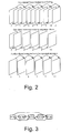
- Figure 2 depicts a scheme referred to as Video Redundancy Coding, where a sequence of pictures is divided into two or more independently coded threads in an interleaved manner.
- the arrows in these and all the subsequent figures indicate the direction of motion compensation and the values under the frames correspond to the relative capturing and displaying times of the frames.
- One fundamental design concept of the JVT codec is to generate self-contained packets, to make mechanisms such as the header duplication unnecessary.
- the way how this was achieved is to decouple information that is relevant to more than one slice from the media stream.
- This higher layer meta information should be sent reliably, asynchronously and in advance from the RTP packet stream that contains the slice packets.
- This information can also be sent in-band in such applications that do not have an out-of-band transport channel appropriate for the purpose.
- the combination of the higher level parameters is called a Parameter Set.
- the Parameter Set contains information such as picture size, display window, optional coding modes employed, macroblock allocation map, and others.
- the encoder and decoder can maintain a list of more than one Parameter Set.
- Each slice header contains a codeword that indicates the Parameter Set to be used.
- This mechanism allows to decouple the transmission of the Parameter Sets from the packet stream, and transmit them by external means, e.g. as a side effect of the capability exchange, or through a (reliable or unreliable) control protocol. It may even be possible that they get never transmitted but are fixed by an application design specification.
- the decoding order of pictures is the same as the display order except for B pictures.
- a block in a conventional B picture can be bi-directionally temporally predicted from two reference pictures, where one reference picture is temporally preceding and the other reference picture is temporally succeeding in display order. Only the latest reference picture in decoding order can succeed the B picture in display order (exception: interlaced coding in H.263 where both field pictures of a temporally subsequent reference frame can precede a B picture in decoding order).
- a conventional B picture cannot be used as a reference picture for temporal prediction, and therefore a conventional B picture can be disposed without affecting the decoding of any other pictures.
- the JVT coding standard includes the following novel technical features compared to earlier standards:
- Decoupling of display order from decoding order can be beneficial from compression efficiency and error resiliency point of view.
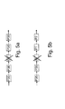
- FIG. 3 An example of a prediction structure potentially improving compression efficiency is presented in Figure 3 .
- Boxes indicate pictures, capital letters within boxes indicate coding types, numbers within boxes are picture numbers according to the JVT coding standard, and arrows indicate prediction dependencies.
- picture B17 is a reference picture for pictures B18.
- Compression efficiency is potentially improved compared to conventional coding, because the reference pictures for pictures B18 are temporally closer compared to conventional coding with PBBP or PBBBP coded picture patterns.
- Compression efficiency is potentially improved compared to conventional PBP coded picture pattern, because part of reference pictures are bi-directionally predicted.
- Figure 4 presents an example of the intra picture postponement method that can be used to improve error resiliency.
- an intra picture is coded immediately after a scene cut or as a response to an expired intra picture refresh period, for example.
- an intra picture is not coded immediately after a need to code an intra picture arises, but rather a temporally subsequent picture is selected as an intra picture.
- Each picture between the coded intra picture and the conventional location of an intra picture is predicted from the next temporally subsequent picture.
- the intra picture postponement method generates two independent inter picture prediction chains, whereas conventional coding algorithms produce a single inter picture chain. It is intuitively clear that the two-chain approach is more robust against erasure errors than the one-chain conventional approach. If one chain suffers from a packet loss, the other chain may still be correctly received. In conventional coding, a packet loss always causes error propagation to the rest of the inter picture prediction chain.
- decoding and presentation order Two types of ordering and timing information have been conventionally associated with digital video: decoding and presentation order. A closer look at the related technology is taken below.
- a decoding timestamp indicates the time relative to a reference clock that a coded data unit is supposed to be decoded. If DTS is coded and transmitted, it serves for two purposes: First, if the decoding order of pictures differs from their output order, DTS indicates the decoding order explicitly. Second, DTS guarantees a certain predecoder buffering (buffering of coded data units for a decoder) behavior provided that the reception rate is close to the transmission rate at any moment. In networks where the end-to-end latency varies, the second use of DTS plays no or little role. Instead, received data is decoded as fast as possible provided that there is room in the post-decoder buffer (for buffering of decoded pictures) for uncompressed pictures.
- DTS decoding timestamp
- DTS Downlink Transport Stream
- DTS Downlink Transport Stream
- SEI Supplemental Enhancement Information
- ISO Base Media File Format DTS is dedicated its own box type, Decoding Time to Sample Box.
- DTS is not carried at all, because decoding order is assumed to be the same as transmission order and exact decoding time does not play an important role.
- H.263 optional Annex U and Annex W.6.12 specify a picture number that is incremented by 1 relative to the previous reference picture in decoding order.
- the frame_num syntax element also referred to as frame number hereinafter
- the JVT coding standard specifies a particular type of an intra picture, called an instantaneous decoding refresh (IDR) picture. No subsequent picture can refer to pictures that are earlier than the IDR picture in decoding order.
- IDR picture is often coded as a response to a scene change.
- H.263 picture number can be used to recover the decoding order of reference pictures.
- the JVT frame number can be used to recover the decoding order of frames between an IDR picture (inclusive) and the next IDR picture (exclusive) in decoding order.
- the complementary reference field pairs consistecutive pictures coded as fields that are of different parity
- the H.263 picture number or JVT frame number of a non-reference picture is specified to be equal to the picture or frame number of the previous reference picture in decoding order plus 1. If several non-reference pictures are consecutive in decoding order, they share the same picture or frame number. The picture or frame number of a non-reference picture is also the same as the picture or frame number of the following reference picture in decoding order.
- the decoding order of consecutive non-reference pictures can be recovered using the Temporal Reference (TR) coding element in H.263 or the Picture Order Count (POC) concept of the JVT coding standard.
- TR Temporal Reference
- POC Picture Order Count
- a presentation timestamp indicates the time relative to a reference clock when a picture is supposed to be displayed.
- a presentation timestamp is also called a display timestamp, output timestamp, and composition timestamp.
- PTS Carriage of PTS depends on the communication system and video coding standard in use.
- PTS can optionally be transmitted as one item in the header of a PES packet.
- PTS can optionally be carried as a part of Supplemental Enhancement Information (SEI), and it is used in the operation of the Hypothetical Reference Decoder.
- SEI Supplemental Enhancement Information
- PTS is dedicated its own box type, Composition Time to Sample Box where the presentation timestamp is coded relative to the corresponding decoding timestamp.
- RTP the RTP timestamp in the RTP packet header corresponds to PTS.
- TR Temporal Reference
- MPEG-2 video TR is reset to zero at the beginning of a Group of Pictures (GOP).
- GOP Group of Pictures
- POC Picture Order Count
- POC is specified for each frame and field and it is used similarly to TR in direct temporal prediction of B slices, for example. POC is reset to 0 at an IDR picture.
- the RTP sequence number is normally a 16-bit unsigned value in the RTP header that is incremented by one for each RTP data packet sent, and may be used by the receiver to detect packet loss and to restore packet sequence.
- a multimedia streaming system consists of a streaming server and a number of players, which access the server via a network.
- the network is typically packet-oriented and provides little or no means to guaranteed quality of service.
- the players fetch either pre-stored or live multimedia content from the server and play it back in real-time while the content is being downloaded.
- the type of communication can be either point-to-point or multicast.
- point-to-point streaming the server provides a separate connection for each player.
- multicast streaming the server transmits a single data stream to a number of players, and network elements duplicate the stream only if it is necessary.
- Initial buffering helps to maintain pauseless playback, because, in case of occasional increased transmission delays or network throughput drops, the player can decode and play buffered data.
- RTP and RTCP protocols can be used on top of UDP to control real-time communications.
- RTP provides means to detect losses of transmission packets, to reassemble the correct order of packets in the receiving end, and to associate a sampling time-stamp with each packet.
- RTCP conveys information about how large a portion of packets were correctly received, and, therefore, it can be used for flow control purposes.
- Bit errors are typically associated with a circuit-switched channel, such as a radio access network connection in mobile communications, and they are caused by imperfections of physical channels, such as radio interference. Such imperfections may result into bit inversions, bit insertions and bit deletions in transmitted data.
- Packet errors are typically caused by elements in packet-switched networks. For example, a packet router may become congested; i.e. it may get too many packets as input and cannot output them at the same rate. In this situation, its buffers overflow, and some packets get lost. Packet duplication and packet delivery in different order than transmitted are also possible but they are typically considered to be less common than packet losses.
- Packet errors may also be caused by the implementation of the used transport protocol stack. For example, some protocols use checksums that are calculated in the transmitter and encapsulated with source-coded data. If there is a bit inversion error in the data, the receiver cannot end up into the same checksum, and it may have to discard the received packet.
- Second (2G) and third generation (3G) mobile networks including GPRS, UMTS, and CDMA-2000, provide two basic types of radio link connections, acknowledged and non-acknowledged.
- An acknowledged connection is such that the integrity of a radio link frame is checked by the recipient (either the Mobile Station, MS, or the Base Station Subsystem, BSS), and, in case of a transmission error, a retransmission request is given to the other end of the radio link. Due to link layer retransmission, the originator has to buffer a radio link frame until a positive acknowledgement for the frame is received. In harsh radio conditions, this buffer may overflow and cause data loss. Nevertheless, it has been shown that it is beneficial to use the acknowledged radio link protocol mode for streaming services.
- a non-acknowledged connection is such that erroneous radio link frames are typically discarded.
- Loss correction refers to the capability to restore lost data perfectly as if no losses had ever been introduced.
- Loss concealment refers to the capability to conceal the effects of transmission losses so that they should not be visible in the reconstructed video sequence.
- a player When a player detects a packet loss, it may request for a packet retransmission. Because of the initial buffering, the retransmitted packet may be received before its scheduled playback time.
- Some commercial Internet streaming systems implement retransmission requests using proprietary protocols. Work is going on in IETF to standardize a selective retransmission request mechanism as a part of RTCP.
- Point-to-point streaming systems may also benefit from non-interactive error control techniques.
- some systems may not contain any interactive error control mechanism or they prefer not to have any feedback from players in order to simplify the system.
- Streaming servers have to ensure that interactive error control methods do not reserve a major portion of the available network throughput. In practice, the servers may have to limit the amount of interactive error control operations.
- transmission delay may limit the number of interactions between the server and the player, as all interactive error control operations for a specific data sample should preferably be done before the data sample is played back.
- Non-interactive packet loss control mechanisms can be categorized to forward error control and loss concealment by post-processing.
- Forward error control refers to techniques in which a transmitter adds such redundancy to transmitted data that receivers can recover at least part of the transmitted data even if there are transmission losses.
- Error concealment by post-processing is totally receiver-oriented. These methods try to estimate the correct representation of erroneously received data.
- Video communication systems can either conceal the loss in displayed images or freeze the latest correct picture onto the screen until a frame which is independent from the corrupted frame is received.
- the decoding order is coupled with the output order.
- the decoding order of I and P pictures is the same as their output order, and the decoding order of a B picture immediately follows the decoding order of the latter reference picture of the B picture in output order. Consequently, it is possible to recover the decoding order based on known output order.
- the output order is typically conveyed in the elementary video bitstream in the Temporal Reference (TR) field and also in the system multiplex layer, such as in the RTP header.
- the JVT coding standard also includes a sub-sequence concept, which can enhance temporal scalability compared to the use of non-reference picture so that inter-predicted chains of pictures can be disposed as a whole without affecting the decodability of the rest of the coded stream.
- a sub-sequence is a set of coded pictures within a sub-sequence layer.
- a picture resides in one sub-sequence layer and in one sub-sequence only.
- a sub-sequence does not depend on any other sub-sequence in the same or in a higher sub-sequence layer.
- a sub-sequence in layer 0 can be decoded independently of any other sub-sequences and previous long-term reference pictures.
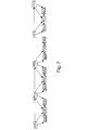
- Fig. 6a discloses an example of a picture stream containing sub-sequences at layer 1.
- a sub-sequence layer contains a subset of the coded pictures in a sequence.
- Sub-sequence layers are numbered with non-negative integers.
- a layer having a larger layer number is a higher layer than a layer having a smaller layer number.
- the layers are ordered hierarchically based on their dependency on each other so that a layer does not depend on any higher layer and may depend on lower layers.
- layer 0 is independently decodable
- pictures in layer 1 may be predicted from layer
- pictures in layer 2 may be predicted from layers 0 and 1, etc.
- the subjective quality is expected to increase along with the number of decoded layers.
- the sub-sequence concept is included in the JVT coding standard as follows:
- the required_frame_num_update_behaviour_flag equal to 1 in the sequence parameter set signals that the coded sequence may not contain all sub-sequences.
- the usage of the required_frame_num_update_behaviour_flag releases the requirement for the frame number increment of 1 for each reference frame. Instead, gaps in frame numbers are marked specifically in the decoded picture buffer. If a "missing" frame number is referred to in inter prediction, a loss of a picture is inferred. Otherwise, frames corresponding to "missing" frame numbers are handled as if they were normal frames inserted to the decoded picture buffer with the sliding window buffering mode. All the pictures in a disposed sub-sequence are consequently assigned a "missing" frame number in the decoded picture buffer, but they are never used in inter prediction for other sub-sequences.
- the JVT coding standard also includes optional sub-sequence related SEI messages.
- the sub-sequence information SEI message is associated with the next slice in decoding order. It signals the sub-sequence layer and sub-sequence identifier (sub_seq_id) of the sub-seuqence to which the slice belongs.
- the slice header of each IDR picture contains an identifier (idr_pic_id). If two IDR pictures are consecutive in decoding order, without any intervening picture, the value of idr_pic_id shall change from the first IDR picture to the other one. If the current picture resides in a sub-sequence whose first picture in decoding order is an IDR picture, the value of sub_seq_id shall be the same as the value of idr_pic_id of the IDR picture.
- Decoding order of coded pictures in the JVT coding standard cannot generally be reconstructed based on frame numbers and sub-sequence identifiers. If transmission order differed from decoding order and coded pictures resided in sub-sequence layer 1, their decoding order relative to pictures in sub-sequence layer 0 could not be concluded based on sub-sequence identifiers and frame numbers. For example, consider the following coding scheme presented on Fig. 6b where output order runs from left to right, boxes indicate pictures, capital letters within boxes indicate coding types, numbers within boxes are frame numbers according to the JVT coding standard, underlined characters indicate non-reference pictures, and arrows indicate prediction dependencies.
- independent GOP is a group of pictures which can be decoded correctly without any other pictures from other group of pictures.
- a primary coded picture is a primary coded representation of a picture.
- the decoded primary coded picture covers the entire picture area, i.e., the primary coded picture contains all slices and macroblocks of the picture.
- a redundant coded picture is a redundant coded representation of a picture or a part of a picture that is not used for decoding unless the primary coded picture is missing or corrupted. The redundant coded picture is not required contain all macroblocks in the primary coded picture.
- Streaming clients typically have a receiver buffer that is capable of storing a relatively large amount of data. Initially, when a streaming session is established, a client does not start playing the stream back immediately, but rather it typically buffers the incoming data for a few seconds. This buffering helps to maintain continuous playback, because, in case of occasional increased transmission delays or network throughput drops, the client can decode and play buffered data. Otherwise, without initial buffering, the client has to freeze the display, stop decoding, and wait for incoming data. The buffering is also necessary for either automatic or selective retransmission in any protocol level. If any part of a picture is lost, a retransmission mechanism may be used to resend the lost data. If the retransmitted data is received before its scheduled decoding or playback time, the loss is perfectly recovered.
- Coded pictures can be ranked according to their importance in the subjective quality of the decoded sequence. For example, non-reference pictures, such as conventional B pictures, are subjectively least important, because their absence does not affect decoding of any other pictures. Subjective ranking can also be made on data partition or slice group basis. Coded slices and data partitions that are subjectively the most important can be sent earlier than their decoding order indicates, whereas coded slices and data partitions that are subjectively the least important can be sent later than their natural coding order indicates. Consequently, any retransmitted parts of the most important slice and data partitions are more likely to be received before their scheduled decoding or playback time compared to the least important slices and data partitions.
- the invention enables reordering of video data from transmission order to decoding order in video communication schemes where it is advantageous to transmit data out of decoding order.
- in-band signalling of decoding order is conveyed from the transmitter to the receiver.
- the signalling may be complementary or substitutive to any signalling, such as frame numbers in the JVT coding standard, within the video bitstream that can be used to recover decoding order.
- an independent GOP consists of pictures from an IDR picture (inclusive) to the next IDR picture (exclusive) in decoding order.
- Each NAL unit in the bitstream includes or is associated with a video sequence ID that remains unchanged for all NAL units within an independent GOP.
- Video sequence ID of an independent GOP shall differ from the video sequence ID of the previous independent GOP in decoding order freely or it shall be incremented compared to the previous video sequence ID (in modulo arithmetic).
- the decoding order of independent GOPs is determined by their reception order. For example, the independent GOP starting with the IDR picture that has the smallest RTP sequence number is decoded first. In the latter case, the independent GOPs are decoded in ascending order of video sequence IDs.
- the stored video signals can be either uncoded signals stored before encoding, as encoded signals stored after encoding, or as decoded signals stored after encoding and decoding process.
- an encoder produces bitstreams in decoding order.
- a file system receives audio and/or video bitstreams which are encapsulated e.g. in decoding order and stored as a file.
- the encoder and the file system can produce metadata which informs subjective importance of the pictures and NAL units, contains information on sub-sequences, inter alia.
- the file can be stored into a database from which a direct playback server can read the NAL units and encapsulate them into RTP packets.
- the direct playback server can modify the transmission order of the packets different from the decoding order, remove sub-sequences, decide what SEI-messages will be transmitted, if any, etc.
- the RTP packets are received and buffered.
- the NAL units are first reordered into correct order and after that the NAL units are delivered to the decoder.
- NAL unit types 1 to 5 are defined as follows:
- a Decoding Order Number indicates the decoding order of NAL units, in other the delivery order of the NAL units to the decoder.
- DON is assumed to be a 16-bit unsigned integer without the loss of generality.
- NAL unit delivery order of NAL units having the same value of DON can, for example, be the following:
- the present invention improves the reliability of the coding systems.
- the correct decoding order of the pictures can be more reliably determined than in prior art systems even if some packets of a video stream are not available in the decoder.
- the pictures to be encoded can be, for example, pictures of a video stream from a video source 3, e.g. a camera, a video recorder, etc.
- the pictures (frames) of the video stream can be divided into smaller portions such as slices.
- the slices can further be divided into blocks.
- the video stream is encoded to reduce the information to be transmitted via a transmission channel 4, or to a storage media (not shown).
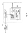
- Pictures of the video stream are input to the encoder 1.
- the encoder has an encoding buffer 1.1 ( Fig.
- the encoder 1 also includes a memory 1.3 and a processor 1.2 in which the encoding tasks according to the invention can be applied.
- the memory 1.3 and the processor 1.2 can be common with the transmitting device 6 or the transmitting device 6 can have another processor and/or memory (not shown) for other functions of the transmitting device 6.
- the encoder 1 performs motion estimation and/or some other tasks to compress the video stream. In motion estimation similarities between the picture to be encoded (the current picture) and a previous and/or latter picture are searched. If similarities are found the compared picture or part of it can be used as a reference picture for the picture to be encoded.
- the display order and the decoding order of the pictures are not necessarily the same, wherein the reference picture has to be stored in a buffer (e.g. in the encoding buffer 1.1) as long as it is used as a reference picture.
- the encoder 1 also inserts information on display order of the pictures into the transmission stream. In practice, either the timing information SEI message or timestamps external to the JVT syntax (such as RTP timestamps) can be used.
- the encoded pictures are moved to an encoded picture buffer 1.2, if necessary.
- the encoded pictures are transmitted from the encoder 1 to the decoder 2 via the transmission channel 4.
- the encoded pictures are decoded to form uncompressed pictures corresponding as much as possible to the encoded pictures.
- Each decoded picture is buffered in the decoded picture buffer (DPB) 2.1 of the decoder 2 unless it is displayed substantially immediately after the decoding and is not used as a reference picture.
- DPB decoded picture buffer
- both the reference picture buffering and the display picture buffering are combined and they use the same decoded picture buffer 2.1. This eliminates the need for storing the same pictures in two different places thus reducing the memory requirements of the decoder 2.
- the decoder 1 also includes a memory 2.3 and a processor 2.2 in which the decoding tasks according to the invention can be applied.
- the memory 2.3 and the processor 2.2 can be common with the receiving device 8 or the receiving device 8 can have another processor and/or memory (not shown) for other functions of the receiving device 8.
- the payload format of RTP packets is defined as a number of different payload structures depending on need. However, which structure a received RTP packet contains is evident from the first byte of the payload. This byte will always be structured as a NAL unit header.
- the NAL unit type field indicates which structure is present.
- the possible structures are: Single NAL Unit Packet, Aggregation packet and Fragmentation unit.
- the Single NAL Unit Packet contains only a single NAL unit in the payload.
- the NAL header type field will be equal to the original NAL unit type, i.e., in the range of 1 to 23, inclusive.
- the Aggregation packet type is used to aggregate multiple NAL units into a single RTP payload.
- This packet exists in four versions, the Single-Time Aggregation Packet type A (STAP-A), the Single-Time Aggregation Packet type B (STAP-B), Multi-Time Aggregation Packet (MTAP) with 16 bit offset (MTAP16), and Multi-Time Aggregation Packet (MTAP) with 24 bit offset (MTAP24).
- the NAL unit type numbers assigned for STAP-A, STAP-B, MTAP16, and MTAP24 are 24, 25, 26, and 27 respectively.
- the Fragmentation unit is used to fragment a single NAL unit over multiple RTP packets. It exists with two versions identified with the NAL unit type numbers 28 and 29.
- the single NAL unit mode is targeted for conversational systems that comply with ITU-T Recommendation H.241.
- the non-interleaved mode is targeted for conversational systems that may not comply with ITU-T Recommendation H.241.
- NAL units are transmitted in NAL unit decoding order.
- the interleaved mode is targeted for systems that do not require very low end-to-end latency.
- the interleaved mode allows transmission of NAL units out of NAL unit decoding order.
- the packetization mode in use may be signaled by the value of the optional packetization-mode MIME parameter or by external means.
- the used packetization mode governs which NAL unit types are allowed in RTP payloads.
- Decoding order number is a field in the payload structure or a derived variable that indicates the NAL unit decoding order.
- the coupling of transmission and decoding order is controlled by the optional interleaving-depth MIME parameter as follows.
- the value of the optional interleaving-depth MIME parameter is equal to 0 and transmission of NAL units out of their decoding order is disallowed, the transmission order of NAL units conforms to the NAL unit decoding order.
- the value of the optional interleaving-depth MIME parameter is greater than 0 or transmission of NAL units out of their decoding order is allowed, in particular,
- the RTP payload structures for a single NAL unit packet, an STAP-A, and an FU-A do not include DON.
- STAP-B and FU-B structures include DON, and the structure of MTAPs enables derivation of DON.
- STAP-B packet type can be used.
- the transmission order of NAL units is the same as their NAL unit decoding order.
- the transmission order of NAL units in single NAL unit packets and STAP-As, and FU-As is the same as their NAL unit decoding order.
- the NAL units within a STAP appear in the NAL unit decoding order.
- values of RTP timestamps may not be monotonically non-decreasing as a function of RTP sequence numbers.
- the DON value of the first NAL unit in transmission order may be set to any value. Values of DON are in the range of 0 to 65535, inclusive. After reaching the maximum value, the value of DON wraps around to 0.
- D1 ⁇ D2 and D2 - D1 > 32768, or if D1 > D2 and D1 - D2 ⁇ 32768, then the NAL unit having a value of DON equal to D2 precedes the NAL unit having a value of DON equal to D1 in NAL unit decoding order.
- Values of DON related fields are such that the decoding order determined by the values of DON as specified above conforms to the NAL unit decoding order. If the order of two consecutive NAL units in the NAL unit stream is switched and the new order still conforms to the NAL unit decoding order, the NAL units may have the same value of DON.
- Receivers should not expect that the absolute difference of values of DON for two consecutive NAL units in the NAL unit decoding order is equal to one even in case of error-free transmission.
- An increment by one is not required, because at the time of associating values of DON to NAL units, it may not be known, whether all NAL units are delivered to the receiver.
- a gateway may not forward coded slice NAL units of non-reference pictures or SEI NAL units, when there is a shortage of bitrate in the network to which the packets are forwarded.
- SEI NAL units a live broadcast is interrupted by pre-encoded content such as commercials from time to time. The first intra picture of a pre-encoded clip is transmitted in advance to ensure that it is readily available in the receiver.
- the originator does not exactly know how many NAL units are going to be encoded before the first intra picture of the pre-encoded clip follows in decoding order.
- the values of DON for the NAL units of the first intra picture of the pre-encoded clip have to be estimated at the time of transmitting them and gaps in values of DON may occur.
- Pictures from the video source 3 are entered to the encoder 1 and advantageously stored in the pre-encoding buffer 1.1.
- the encoding process is not necessarily started immediately after the first picture is entered to the encoder, but after a certain amount of pictures are available in the encoding buffer 1.1.
- the encoder 1 tries to find suitable candidates from the pictures to be used as the reference frames.
- the encoder 1 then performs the encoding to form encoded pictures.
- the encoded pictures can be, for example, predicted pictures (P), bi-predictive pictures (B), and/or intra-coded pictures (I).
- the intra-coded pictures can be decoded without using any other pictures, but other type of pictures need at least one reference picture before they can be decoded. Pictures of any of the above mentioned picture types can be used as a reference picture.
- the encoder advantageously attaches two time stamps to the pictures: a decoding time stamp (DTS) and output time stamp (OTS).
- DTS decoding time stamp
- OTS output time stamp
- the decoder can use the time stamps to determine the correct decoding time and time to output (display) the pictures.
- those time stamps are not necessarily transmitted to the decoder or it does not use them.
- the encoder also forms sub-sequences on one or more layers above the lowest layer 0.
- the sub-sequences on layer 0 are independently decodable, but the pictures on higher layers may depend on pictures on some lower layer or layers.
- layer 0 there are two layers: layer 0 and layer 1.
- the pictures 10, P6 and P12 belong to the layer 0 while other pictures P1-P5, P7-P11 shown on Fig. 6a belong to the layer 1.
- the encoder forms groups of pictures (GOP) so that each picture of one GOP can be reconstructed by using only the pictures in the same GOP.
- GOP groups of pictures
- one GOP contains at least one independently decodable picture and all the other pictures for which the independently decodable picture is a reference picture or a first reference picture in the chain of reference pictures.
- the first independent group of pictures includes the pictures I0(0), P1(0), P3(0) on layer 0, and pictures B2(0), 2xB3(0), B4(0), 2xB5(0), B6(0), P5(0), P6(0) on layer 1.
- the second independent group of pictures includes the pictures I0(1), and P1 (1) on layer 0, and pictures 2xB3(1) and B2(1) on layer 1.
- the pictures on layer 1 of each independent group of pictures are further arranged as sub-sequences.
- the first sub-sequence of the first independent group of pictures contains pictures B3(0), B2(0), B3(0)
- the second sub-sequence contains pictures B5(0), B4(0), B5(0)
- the third sub-sequence contains pictures B6(0), P5(0), P6(0).
- the sub-sequence of the second independent group of pictures contains pictures B3(1), B2(1), B3(1).
- the numbers in brackets indicate the video sequence ID defined for the independent group of pictures in which the picture belongs.
- the video sequence ID is transferred for each picture. It can be conveyed within the video bitstream, such as in the Supplemental Enhancement Information data.
- the video sequence ID can also be transmitted in the header fields of the transport protocol, such as within the RTP payload header of the JVT coding standard.
- the video sequence ID according to the presented partitioning to independent GOPs can be stored in the metadata of the video file format, such as in the MPEG-4 AVC file format.
- the encoder initialises a decoding order number (DON) to an appropriate starting value, e.g. 0.
- DON decoding order number
- An increasing numbering scheme with wrap around is assumed here, having a certain maximum value. If, for example, the decoding order number is 16-bit unsigned integer, the maximum value is 65535.
- the encoder forms one or more NAL units from each primary encoded picture.
- the encoder can define the same decoding order number for each NAL unit of the same picture, and if redundant coded pictures (sub-sequences on higher layers) exist, the encoder can assign a different DON for NAL units of those redundant coded pictures.
- the encoder When the whole primary encoded picture and its possible redundant encoded pictures are encoded, the encoder begins to handle the next primary coded picture in decoding order.
- the encoder increments the decoding order number preferably by one, if the value of the decoding order number is smaller than said maximum value. If the decoding order number has the maximum value, the encoder sets the decoding order value to the minimum value which preferably is 0. Then, the encoder forms NAL units from said next primary encoded picture and assigns them the current value of the decoding order number. Respectively, if there exists any redundant encoded pictures of the same primary encoded picture, those are also transformed into NAL units. The operation continues until all the primary encoded pictures and respective redundant encoded pictures, if any, are handled. The transmitting device can begin to transmit the NAL units before all pictures are handled.
- the encoder should assign an ascending value of DON for each slice of a primary coded picture in raster scan order. That is, if a slice is transmitted in a single NAL unit each successive NAL unit has a different value of DON. If a slice is transmitted as data partition NAL units, each data partition NAL unit of a slice can share the same value of DON. For a slice of a redundant coded picture, the encoder assigns a value of DON that is larger than the value of DON of the corresponding slice in the corresponding primary coded picture.
- the decoding order numbers can be used to determine the correct decoding order of the encoded pictures.
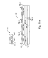
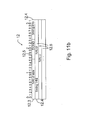
- Figs. 11 a and 11 b disclose examples of the NAL packet formats which can be used with the present invention.
- the packet contains a header 11 and a payload part 12.
- the header 11 contains advantageously an error indicator field 11.1 (F, Forbidden), a priority field 11.2, and a type field 11.3.
- the error indicator field 11.1 indicates a bit error free NAL unit.
- the decoder is advised that bit errors may be present in the payload or in the NALU type octet. Decoders that are incapable of handling bit errors can then discard such packets.
- the priority field 11.2 is used for indicating the importance of the picture encapsulated in the payload part 12 of the packet.
- the priority field can have four different values as follows.
- a value of 00 indicates that the content of the NALU is not used to reconstruct reference pictures (that can be used for future reference). Such NALUs can be discarded without risking the integrity of the reference pictures.
- Values above 00 indicate that the decoding of the NALU is required to maintain the integrity of the reference pictures.
- values above 00 indicate the relative transport priority, as determined by the encoder. Intelligent network elements can use this information to protect more important NALUs better than less important NALUs. 11 is the highest transport priority, followed by 10, then by 01 and, finally, 00 is the lowest.
- the payload part 12 of the NALU contains at least a video sequence ID field 12.1, a field indicator 12.2, size field 12.3, timing info 12.4 and the encoded picture information 12.5.
- the video sequence ID field 12.1 is used for storing the number of the video sequence in which the picture belongs to.
- the field indicator 12.2 is used to signal whether the picture is a first or a second frame when two-frame picture format is used. Both frames may be coded as separate pictures.
- the first field indicator equal to 1 advantageously signals that the NALU belongs to a coded frame or a coded field that precedes the second coded field of the same frame in decoding order.
- the first field indicator equal to 0 signals that the NALU belongs to a coded field that succeeds the first coded field of the same frame in decoding order.
- the timing info field 11.3 is used for transforming time related information, if necessary.
- the NAL units can be delivered in different kinds of packets.
- the different packet formats include simple packets and aggregation packets.
- the aggregation packets can further be divided into single-time aggregation packets and multi-time aggregation packets.
- a simple packet according to this invention consists of one NALU.
- a NAL unit stream composed by decapsulating Simple Packets in RTP sequence number order should conform to the NAL unit delivery order.
- Aggregation packets are the packet aggregation scheme of this payload specification. The scheme is introduced to reflect the dramatically different MTU sizes of two different type of networkswireline IP networks (with an MTU size that is often limited by the Ethernet MTU size -- roughly 1500 bytes), and IP or non-IP (e.g. H.324/M) based wireless networks with preferred transmission unit sizes of 254 bytes or less.
- a packet aggregation scheme is introduced.
- Single-Time Aggregation Packet aggregate NALUs with identical NALU-time.
- Multi-Time Aggregation Packets aggregate NALUs with potentially differing NALU-time.
- Two different MTAPs are defined that differ in the length of the NALU timestamp offset.
- NALU-time is defined as the value the RTP timestamp would have if that NALU would be transported in its own RTP packet.
- the RTP timestamp must be set to the minimum of the NALU times of all the NALUs to be aggregated.
- the Type field of the NALU type octet must be set to the appropriate value as indicated in table 1.
- the error indicator field 11.1 must be cleared if all error indicator fields of the aggregated NALUs are zero, otherwise it must be set.
- the NALU Payload of an aggregation packet consists of one or more aggregation units.
- An aggregation packet can carry as many aggregation units as necessary, however the total amount of data in an aggregation packet obviously must fit into an IP packet, and the size should be chosen such that the resulting IP packet is smaller than the MTU size.
- Single-Time Aggregation Packet should be used whenever aggregating NALUs that share the same NALU-time.
- the NALU payload of an STAP consists of the video sequence ID field 12.1 (e.g. 7 bits) and the field indicator 12.2 followed by Single-Picture Aggregation Units (SPAU).
- SPAU Single-Picture Aggregation Units
- STAP-B Single-Time Aggregation Packet type B includes also the DON.
- a video sequence according to this specification can be any part of NALU stream that can be decoded independently from other parts of the NALU stream.
- a frame consists of two fields that may be coded as separate pictures.
- the first field indicator equal to 1 signals that the NALU belongs to a coded frame or a coded field that precedes the second coded field of the same frame in decoding order.
- the first field indicator equal to 0 signals that the NALU belongs to a coded field that succeeds the first coded field of the same frame in decoding order.
- a Single-Picture Aggregation Unit consists of e.g. 16-bit unsigned size information that indicates the size of the following NALU in bytes (excluding these two octets, but including the NALU type octet of the NALU), followed by the NALU itself including its NALU type byte.
- a Multi-Time Aggregation Packet has a similar architecture as an STAP. It consists of the NALU header byte and one or more Multi-Picture Aggregation Units. The choice between the different MTAP fields is application dependent -- the larger the timestamp offset is the higher is the flexibility of the MTAP, but the higher is also the overhead.
- Two different Multi-Time Aggregation Units are defined in this specification. Both of them consist of e.g . 16 bits unsigned size information of the following NALU (same as the size information of in the STAP). In addition to these 16 bits there are also the video sequence ID field 12.1 ( e.g. 7 bits), the field indicator 12.2 and n bits of timing information for this NALU, whereby n can e.g. be 16 or 24.
- the timing information field has to be set so that the RTP timestamp of an RTP packet of each NALU in the MTAP (the NALU-time) can be generated by adding the timing information from the RTP timestamp of the MTAP.
- the Multi-Time Aggregation Packet consists of the NALU header byte, a decoding order number base (DONB) field 12.1 (e.g. 16 bits), and one or more Multi-Picture Aggregation Units.
- the two different Multi-Time Aggregation Units are in this case defined as follows. Both of them consist of e.g. 16 bits unsigned size information of the following NALU (same as the size information of in the STAP).
- the decoding order number delta (DOND) field 12.5 e.g. 7 bits
- n bits of timing information for this NAL whereby n can e.g. be 16 or 24.
- DON of the following NALU is equal to DONB + DOND.
- the timing information field has to be set so that the RTP timestamp of an RTP packet of each NALU in the MTAP (the NALU-time) can be generated by adding the timing information from the RTP timestamp of the MTAP.
- DONB may contain the smallest value of DON among the NAL units of the MTAP.
- the transmission and/or storing of the encoded pictures (and the optional virtual decoding) can be started immediately after the first encoded picture is ready.
- This picture is not necessarily the first one in decoder output order because the decoding order and the output order may not be the same.
- the transmission can be started.
- the encoded pictures are optionally stored to the encoded picture buffer 1.2.
- the transmission can also start at a later stage, for example, after a certain part of the video stream is encoded.
- the decoder 2 should also output the decoded pictures in correct order, for example by using the ordering of the picture order counts, and hence the reordering process need be defined clearly and normatively.
- de-packetization process is implementation dependent. Hence, the following description is a non-restrictive example of a suitable implementation. Other schemes may be used as well. Optimizations relative to the described algorithms are likely possible.
- the receiver 8 collects all packets belonging to a picture, bringing them into a reasonable order. The strictness of the order depends on the profile employed.
- the received packets are advantageously stored into the receiving buffer 9.1 (pre-decoding buffer).
- the receiver 8 discards anything that is unusable, and passes the rest to the decoder 2.
- Aggregation packets are handled by unloading their payload into individual RTP packets carrying NALUs. Those NALUs are processed as if they were received in separate RTP packets, in the order they were arranged in the Aggregation Packet.
- the RTP sequence number of the packet that contained the NAL unit is advantageously stored and associated with the stored NAL unit.
- the packet type (Simple Packet or Aggregation Packet) that contained the NAL unit is stored and associated with each stored NAL unit.
- N the value of the optional num-reorder-VCL-NAL-units parameter (interleaving-depth parameter) which specifies the maximum amount of VCL NAL units that precede any VCL NAL unit in the packet stream in NAL unit delivery order and follow the VCL NAL unit in RTP sequence number order or in the composition order of the aggregation packet containing the VCL NAL unit. If the parameter is not present, a 0 value number could be implied.
- the receiver buffers at least N pieces of VCL NAL units into the receiving buffer 9.1 before passing any packet to the decoder 2.
- NAL units are removed from the receiver buffer 9.1 and passed to the decoder 2 in the order specified below until the buffer contains N-1 VCL NAL units.
- PVSID the video sequence ID (VSID) of the latest NAL unit passed to the decoder. All NAL units in a STAP share the same VSID.
- the order in which NAL units are passed to the decoder is specified as follows: If the oldest RTP sequence number in the buffer corresponds to a Simple Packet, the NALU in the Simple Packet is the next NALU in the NAL unit delivery order. If the oldest RTP sequence number in the buffer corresponds to an Aggregation Packet, the NAL unit delivery order is recovered among the NALUs conveyed in Aggregation Packets in RTP sequence number order until the next Simple Packet (exclusive). This set of NALUs is hereinafter referred to as the candidate NALUs. If no NALUs conveyed in Simple Packets reside in the buffer, all NALUs belong to candidate NALUs.
- a VSID distance is calculated as follows. If the VSID of the NAL unit is larger than PVSID, the VSID distance is equal to VSID - PVSID. Otherwise, the VSID distance is equal to 2 ⁇ (number of bits used to signal VSID) - PVSID + VSID. NAL units are delivered to the decoder in ascending order of VSID distance. If several NAL units share the same VSID distance, the order to pass them to the decoder shall conform to the NAL unit delivery order defined in this specification. The NAL unit delivery order can be recovered as described in the following.
- PVSID the decoding order number of the previous NAL unit of an aggregation packet in NAL unit delivery order
- DON decoding order number
- slices and data partitions are associated with pictures according to their frame numbers, RTP timestamps and first field flags: all NALUs sharing the same values of the frame number, the RTP timestamp and the first field flag belong to the same picture.
- SEI NALUs, sequence parameter set NALUs, picture parameter set NALUs, picture delimiter NALUs, end of sequence NALUs, end of stream NALUs, and filler data NALUs belong to the picture of the next VCL NAL unit in transmission order.
- the delivery order of the pictures is concluded based on nal_ref_idc, the frame number, the first field flag, and the RTP timestamp of each picture.
- the delivery order of pictures is in ascending order of frame numbers (in modulo arithmetic). If several pictures share the same value of frame number, the picture(s) that have nal-ref-idc equal to 0 are delivered first. If several pictures share the same value of frame number and they all have nal_ref_idc equal to 0, the pictures are delivered in ascending RTP timestamp order. If two pictures share the same RTP timestamp, the picture having first field flag equal to 1 is delivered first. Note that a primary coded picture and the corresponding redundant coded pictures are herein considered as one coded picture.
- the delivery order of slices and A data partitions is in ascending order of the first_mb_in_slice syntax element in the slice header. Moreover, B and C data partitions immediately follow the corresponding A data partition in delivery order.
- NALUs are presented to the JVT decoder in the order of the RTP sequence number.
- NALUs carried in an Aggregation Packet are presented in their order in the Aggregation packet. All NALUs of the Aggregation packet are processed before the next RTP packet is processed.
- Intelligent RTP receivers may identify lost DPAs. If a lost DPA is found, the Gateway MAY decide not to send the DPB and DPC partitions, as their information is meaningless for the JVT Decoder. In this way a network element can reduce network load by discarding useless packets, without parsing a complex bit stream.
- Intelligent receivers may discard all packets that have a NAL Reference Idc of 0. However, they should process those packets if possible, because the user experience may suffer if the packets are discarded.
- the DPB 2.1 contains memory places for storing a number of pictures. Those places are also called as frame stores in the description.
- the decoder 2 decodes the received pictures in correct order. To do so the decoder examines the video sequence ID information of the received pictures. If the encoder has selected the video sequence ID for each independent group of pictures freely, the decoder decodes the pictures of the independent group of pictures in the order in which they are received. If the encoder has defined for each independent group of pictures the video sequence ID by using incrementing (or decrementing) numbering scheme, the decoder decodes the independent group of pictures in the order of video sequence IDs. In other words, the independent group of pictures having the smallest (or biggest) video sequence ID is decoded first.
- the present invention can be applied in many kind of systems and devices.
- the transmitting device 6 including the encoder 1 and optionally the HRD 5 advantageously include also a transmitter 7 to transmit the encoded pictures to the transmission channel 4.
- the receiving device 8 include the receiver 9 to receive the encoded pictures, the decoder 2, and a display 10 on which the decoded pictures can be displayed.
- the transmission channel can be, for example, a landline communication channel and/or a wireless communication channel.
- the transmitting device and the receiving device include also one or more processors 1.2, 2.2 which can perform the necessary steps for controlling the encoding/decoding process of video stream according to the invention. Therefore, the method according to the present invention can mainly be implemented as machine executable steps of the processors.
- the buffering of the pictures can be implemented in the memory 1.3, 2.3 of the devices.
- the program code 1.4 of the encoder can be stored into the memory 1.3.
- the program code 2.4 of the decoder can be stored into the memory 2.3.
Landscapes
- Engineering & Computer Science (AREA)
- Multimedia (AREA)
- Signal Processing (AREA)
- Computer Networks & Wireless Communication (AREA)
- Computer Security & Cryptography (AREA)
- Compression Or Coding Systems Of Tv Signals (AREA)
- Compression, Expansion, Code Conversion, And Decoders (AREA)
- Two-Way Televisions, Distribution Of Moving Picture Or The Like (AREA)
- Detection And Prevention Of Errors In Transmission (AREA)
Claims (11)
- Verfahren zum Ordnen von codierten Bildern, die ein erstes und ein zweites codiertes Bild umfassen, wobei sich eine Übertragungsreihenfolge von Daten von einer Decodierungsreihenfolge unterscheidet, mindestens eine erste Übertragungseinheit auf der Grundlage des ersten codierten Bilds gebildet wird und mindestens eine zweite Übertragungseinheit auf der Grundlage des zweiten codierten Bilds gebildet wird, so dass die erste Übertragungseinheit eine erste Scheibe des ersten codierten Bilds enthält und die zweite Übertragungseinheit eine zweite Scheibe des zweiten codierten Bilds enthält, wobei die erste und zweite Übertragungseinheit Netzwerkabstraktionsschichteinheiten von codierten Bildinformationen aufweisen, wobei die erste und zweite Übertragungseinheit im selben Multi-Time Aggregation Real-Time Transport Protocol(RTP)-Paket enthalten sind, wobei die erste und zweite Übertragungseinheit Timing-Informationen in dem Multi-Time Aggregation-Paket zum Festlegen des Präsentationstimings der ersten und zweiten Übertragungseinheit aufweisen, und wobei das RTP-Paket eine RTP-Sequenznummer aufweist, wobei zusätzlich zu den Timing-Informationen und der RTP-Sequenznummer eine erste Kennung für die erste Übertragungseinheit definiert wird, eine zweite Kennung für die zweite Übertragungseinheit definiert wird, wobei die erste und die zweite Kennung die jeweilige Decodierungsreihenfolge von Informationen, die in der ersten Übertragungseinheit enthalten sind, und Informationen anzeigen, die in der zweiten Übertragungseinheit enthalten sind, wobei die erste und die zweite Kennung in dem Multi-Time Aggregation-Paket mittels einer gemeinsamen Decodierungsreihenfolgenzahlenbasis und einer ersten bzw. zweiten Decodierungsreihenfolgenzahldifferenz codiert werden.
- Verfahren nach Anspruch 1, wobei die erste und die zweite Kennung als ganze Zahlen definiert sind, die die Decodierungsreihenfolge der Netzwerkabstraktionsschichteinheiten anzeigen.
- Vorrichtung zum Ordnen von codierten Bildern, die ein erstes und ein zweites codiertes Bild umfassen, wobei sich eine Übertragungsreihenfolge von Daten von einer Decodierungsreihenfolge unterscheidet, wobei die Vorrichtung eine Anordnungseinrichtung zur Bildung mindestens einer ersten Übertragungseinheit auf der Grundlage des ersten codierten Bilds und mindestens einer zweiten Übertragungseinheit auf der Grundlage des zweiten codierten Bilds aufweist, so dass die erste Übertragungseinheit eine erste Scheibe des ersten codierten Bilds enthält und die zweite Übertragungseinheit eine zweite Scheibe des zweiten codierten Bilds enthält, wobei die erste und zweite Übertragungseinheit Netzwerkabstraktionsschichteinheiten von codierten Bildinformationen aufweisen, wobei die erste und zweite Übertragungseinheit im selben Multi-Time Aggregation Real-Time Transport Protocol(RTP)-Paket enthalten sind, wobei die erste und zweite Übertragungseinheit Timing-Informationen in dem Multi-Time Aggregation-Paket zum Festlegen des Präsentationstimings der ersten und zweiten Übertragungseinheit aufweisen, und wobei das RTP-Paket eine RTP-Sequenznummer aufweist, wobei die Vorrichtung ferner eine Definitionseinrichtung aufweist, um zusätzlich zu den Timing-Informationen und der RTP-Sequenznummer eine erste Kennung für die erste Übertragungseinheit und eine zweite Kennung für die zweite Übertragungseinheit zu definieren, wobei die erste und die zweite Kennung die jeweilige Decodierungsreihenfolge von Informationen, die in der ersten Übertragungseinheit enthalten sind, und Informationen anzeigen, die in der zweiten Übertragungseinheit enthalten sind, wobei die erste und die zweite Kennung in dem Multi-Time Aggregation-Paket mittels einer gemeinsamen Decodierungsreihenfolgenzahlenbasis und einer ersten bzw. zweiten Decodierungsreihenfolgenzahldifferenz codiert werden.
- Vorrichtung nach Anspruch 3, wobei es eine Gateway-Vorrichtung, eine Mobilkommunikationsvorrichtung oder ein Streaming-Server ist.
- Encoder zur Codierung von Bildern und zum Ordnen von codierten Bildern, die ein erstes und ein zweites codiertes Bild umfassen, wobei sich eine Übertragungsreihenfolge von Daten von einer Decodierungsreihenfolge unterscheidet, wobei der Encoder eine Anordnungseinrichtung zur Bildung mindestens einer ersten Übertragungseinheit auf der Grundlage des ersten codierten Bilds und mindestens einer zweiten Übertragungseinheit auf der Grundlage des zweiten codierten Bilds aufweist, so dass die erste Übertragungseinheit eine erste Scheibe des ersten codierten Bilds enthält und die zweite Übertragungseinheit eine zweite Scheibe des zweiten codierten Bilds enthält, wobei die erste und zweite Übertragungseinheit Netzwerkabstraktionsschichteinheiten von codierten Bildinformationen aufweisen, wobei die erste und zweite Übertragungseinheit im selben Multi-Time Aggregation Real-Time Transport Protocol(RTP)-Paket enthalten sind, wobei die erste und zweite Übertragungseinheit Timing-Informationen in dem Multi-Time Aggregation-Paket zum Festlegen des Präsentationstimings der ersten und zweiten Übertragungseinheit aufweisen, und wobei das RTP-Paket eine RTP-Sequenznummer aufweist, wobei der Encoder ferner eine Definitionseinrichtung aufweist, um zusätzlich zu den Timing-Informationen und der RTP-Sequenznummer eine erste Kennung für die erste Übertragungseinheit und eine zweite Kennung für die zweite Übertragungseinheit zu definieren, wobei die erste und die zweite Kennung die jeweilige Decodierungsreihenfolge von Informationen, die in der ersten Übertragungseinheit enthalten sind, und Informationen anzeigen, die in der zweiten Übertragungseinheit enthalten sind, wobei die erste und die zweite Kennung in dem Multi-Time Aggregation-Paket mittels einer gemeinsamen Decodierungsreihenfolgenzahlenbasis und einer ersten bzw. zweiten Decodierungsreihenfolgenzahldifferenz codiert werden.
- Encoder nach Anspruch 5, wobei die erste und die zweite Kennung als ganze Zahlen definiert sind, die die Decodierungsreihenfolge der Netzwerkabstraktionsschichteinheiten anzeigen.
- Decoder zur Decodierung der codierten Bilder zur Bildung decodierter Bilder, wobei sich eine Übertragungsreihenfolge von Daten von einer Decodierungsreihenfolge unterscheidet, wobei die codierten Bilder ein erstes und ein zweites codiertes Bild umfassen, die in mindestens einer ersten Übertragungseinheit, die auf der Grundlage des ersten codierten Bilds gebildet wird, und in mindestens einer zweiten Übertragungseinheit übertragen werden, die auf der Grundlage des zweiten codierten Bilds gebildet wird, so dass die erste Übertragungseinheit eine erste Scheibe des ersten codierten Bilds enthält und die zweite Übertragungseinheit eine zweite Scheibe des zweiten codierten Bilds enthält, wobei die erste und zweite Übertragungseinheit Netzwerkabstraktionsschichteinheiten von codierten Bildinformationen aufweisen, wobei die erste und zweite Übertragungseinheit im selben Multi-Time Aggregation Real-Time Transport Protocol(RTP)-Paket enthalten sind, wobei die erste und zweite Übertragungseinheit Timing-Informationen in dem Multi-Time Aggregation-Paket zum Festlegen des Präsentationstimings der ersten und zweiten Übertragungseinheit aufweisen, und wobei das RTP-Paket eine RTP-Sequenznummer aufweist, wobei der Decoder ferner einen Prozessor zur Festlegung der Decodierungsreihenfolge von Informationen, die in der ersten Übertragungseinheit enthalten sind, und von Informationen, die in der zweiten Übertragungseinheit enthalten sind, auf der Grundlage einer ersten Kennung, die für die erste Übertragungseinheit definiert ist, und einer zweiten Kennung aufweist, die für die zweite Übertragungseinheit definiert ist, wobei die erste und die zweite Kennung in dem Multi-Time Aggregation-Paket mittels einer gemeinsamen Decodierungsreihenfolgenzahlenbasis und einer ersten bzw. zweiten Decodierungsreihenfolgenzahldifferenz codiert werden.
- Decoder nach Anspruch 7, wobei die erste und die zweite Kennung als ganze Zahlen definiert sind, die die Decodierungsreihenfolge der Netzwerkabstraktionsschichteinheiten anzeigen.
- System, das einen Encoder nach Anspruch 5 oder 6 zur Codierung von Bildern und einen Decoder nach Anspruch 7 oder 8 zur Decodierung der codierten Bilder aufweist.
- Computerprogrammprodukt, das maschinenausführbare Schritte zur Ausführung eines Verfahrens zum Ordnen von codierten Bildern aufweist, die ein erstes und ein zweites codiertes Bild umfassen, wobei sich eine Übertragungsreihenfolge von Daten von einer Decodierungsreihenfolge unterscheidet, zur Bildung mindestens einer ersten Übertragungseinheit auf der Grundlage des ersten codierten Bilds, und mindestens einer zweiten Übertragungseinheit auf der Grundlage des zweiten codierten Bilds, so dass die erste Übertragungseinheit eine erste Scheibe des ersten codierten Bilds enthält und die zweite Übertragungseinheit eine zweite Scheibe des zweiten codierten Bilds enthält, wobei die erste und zweite Übertragungseinheit Netzwerkabstraktionsschichteinheiten von codierten Bildinformationen aufweisen, wobei die erste und zweite Übertragungseinheit im selben Multi-Time Aggregation Real-Time Transport Protocol(RTP)-Paket enthalten sind, wobei die erste und zweite Übertragungseinheit Timing-Informationen in dem Multi-Time Aggregation-Paket zum Festlegen des Präsentationstimings der ersten und zweiten Übertragungseinheit aufweisen, und wobei das RTP-Paket eine RTP-Sequenznummer aufweist, wobei das Computerprogramm ferner maschinenausführbare Schritte aufweist, um zusätzlich zu den Timing-Informationen und der RTP-Sequenznummer eine erste Kennung für die erste Übertragungseinheit und eine zweite Kennung für die zweite Übertragungseinheit zu definieren, wobei die erste und die zweite Kennung die jeweilige Decodierungsreihenfolge von Informationen, die in der ersten Übertragungseinheit enthalten sind, und Informationen anzeigen, die in der zweiten Übertragungseinheit enthalten sind, wobei die erste und die zweite Kennung in dem Multi-Time Aggregation-Paket mittels einer gemeinsamen Decodierungsreihenfolgenzahlenbasis und einer ersten bzw. zweiten Decodierungsreihenfolgenzahldifferenz codiert werden.
- Signal, das mindestens eine erste Übertragungseinheit, die auf der Grundlage eines ersten codierten Bilds gebildet wird, wobei sich eine Übertragungsreihenfolge von Daten von einer Decodierungsreihenfolge unterscheidet, und mindestens eine zweite Übertragungseinheit enthält, die auf der Grundlage eines zweiten codierten Bilds gebildet wird, so dass die erste Übertragungseinheit eine erste Scheibe des ersten codierten Bilds enthält und die zweite Übertragungseinheit eine zweite Scheibe des zweiten codierten Bilds enthält, wobei die erste und zweite Übertragungseinheit Netzwerkabstraktionsschichteinheiten von codierten Bildinformationen aufweisen, wobei die erste und zweite Übertragungseinheit im selben Multi-Time Aggregation Real-Time Transport Protocol(RTP)-Paket enthalten sind, wobei die erste und zweite Übertragungseinheit Timing-Informationen in dem Multi-Time Aggregation-Paket zum Festlegen des Präsentationstimings der ersten und zweiten Übertragungseinheit aufweisen, und wobei das RTP-Paket eine RTP-Sequenznummer aufweist, wobei das Signal ferner zusätzlich zu den Timing-Informationen und der RTP-Sequenznummer eine erste Kennung, die für die erste Übertragungseinheit definiert ist, und eine zweite Kennung enthält, die für die zweite Übertragungseinheit definiert ist, wobei die erste und die zweite Kennung die jeweilige Decodierungsreihenfolge von Informationen, die in der ersten Übertragungseinheit enthalten sind, und Informationen anzeigen, die in der zweiten Übertragungseinheit enthalten sind, wobei die erste und die zweite Kennung in dem Multi-Time Aggregation-Paket mittels einer gemeinsamen Decodierungsreihenfolgenzahlenbasis und einer ersten bzw. zweiten Decodierungsreihenfolgenzahldifferenz codiert werden.
Applications Claiming Priority (3)
| Application Number | Priority Date | Filing Date | Title |
|---|---|---|---|
| US44818903P | 2003-02-18 | 2003-02-18 | |
| US448189P | 2003-02-18 | ||
| PCT/FI2004/050015 WO2004075554A1 (en) | 2003-02-18 | 2004-02-17 | Picture decoding method |
Publications (2)
| Publication Number | Publication Date |
|---|---|
| EP1595404A1 EP1595404A1 (de) | 2005-11-16 |
| EP1595404B1 true EP1595404B1 (de) | 2014-10-22 |
Family
ID=32908554
Family Applications (1)
| Application Number | Title | Priority Date | Filing Date |
|---|---|---|---|
| EP04711623.1A Expired - Lifetime EP1595404B1 (de) | 2003-02-18 | 2004-02-17 | Bilddecodierungsverfahren |
Country Status (9)
| Country | Link |
|---|---|
| US (1) | US8532194B2 (de) |
| EP (1) | EP1595404B1 (de) |
| JP (2) | JP2006518127A (de) |
| CN (2) | CN101668215A (de) |
| MX (1) | MXPA05008405A (de) |
| MY (1) | MY136056A (de) |
| TW (1) | TWI293228B (de) |
| WO (1) | WO2004075554A1 (de) |
| ZA (1) | ZA200506149B (de) |
Families Citing this family (82)
| Publication number | Priority date | Publication date | Assignee | Title |
|---|---|---|---|---|
| US7003035B2 (en) | 2002-01-25 | 2006-02-21 | Microsoft Corporation | Video coding methods and apparatuses |
| US20040001546A1 (en) | 2002-06-03 | 2004-01-01 | Alexandros Tourapis | Spatiotemporal prediction for bidirectionally predictive (B) pictures and motion vector prediction for multi-picture reference motion compensation |
| US7154952B2 (en) | 2002-07-19 | 2006-12-26 | Microsoft Corporation | Timestamp-independent motion vector prediction for predictive (P) and bidirectionally predictive (B) pictures |
| AU2004214313B2 (en) * | 2003-02-18 | 2010-05-20 | Nokia Technologies Oy | Picture coding method |
| KR100941123B1 (ko) * | 2003-10-09 | 2010-02-10 | 톰슨 라이센싱 | 에러 은닉을 위한 직접 모드 도출 프로세스 |
| US20050201471A1 (en) * | 2004-02-13 | 2005-09-15 | Nokia Corporation | Picture decoding method |
| US7542435B2 (en) * | 2004-05-12 | 2009-06-02 | Nokia Corporation | Buffer level signaling for rate adaptation in multimedia streaming |
| US9124907B2 (en) * | 2004-10-04 | 2015-09-01 | Nokia Technologies Oy | Picture buffering method |
| MX2007004142A (es) | 2004-10-05 | 2008-02-15 | Vectormax Corp | Metodo y sistema para difundir datos en multimedia. |
| US20060080436A1 (en) * | 2004-10-07 | 2006-04-13 | Nokia Corporation | System and method for multimedia streaming using interleaved packetization |
| DE102004053877A1 (de) * | 2004-11-04 | 2006-05-18 | Mediatek Inc. | Verfahren zur Media File Aufnahme und der Wiederherstellung nach einem Stromausfall und entsprechende Geräte |
| US7751324B2 (en) * | 2004-11-19 | 2010-07-06 | Nokia Corporation | Packet stream arrangement in multimedia transmission |
| WO2006106185A1 (en) * | 2005-04-07 | 2006-10-12 | Nokia Corporation | Buffering in streaming delivery |
| CN100459717C (zh) * | 2005-04-20 | 2009-02-04 | 华为技术有限公司 | 基于h.264的压缩视频传输误码消除方法 |
| BRPI0613522B1 (pt) * | 2005-07-25 | 2019-09-17 | Interdigital Madison Patent Holdings | Método e aparelho para a detecção e ocultamento de quadros de vídeo de referência e de não-referência |
| KR20070038396A (ko) | 2005-10-05 | 2007-04-10 | 엘지전자 주식회사 | 영상 신호의 인코딩 및 디코딩 방법 |
| KR100772868B1 (ko) * | 2005-11-29 | 2007-11-02 | 삼성전자주식회사 | 복수 계층을 기반으로 하는 스케일러블 비디오 코딩 방법및 장치 |
| CN101326833B (zh) * | 2005-12-07 | 2012-11-14 | 汤姆森特许公司 | 利用参考帧选择规则进行视频错误隐藏的方法与装置 |
| CN105049894B (zh) * | 2005-12-08 | 2018-03-16 | 维德约股份有限公司 | 用于视频通信系统中的差错弹性和随机接入的系统和方法 |
| US9182228B2 (en) | 2006-02-13 | 2015-11-10 | Sony Corporation | Multi-lens array system and method |
| US8767836B2 (en) * | 2006-03-27 | 2014-07-01 | Nokia Corporation | Picture delimiter in scalable video coding |
| US8599841B1 (en) | 2006-03-28 | 2013-12-03 | Nvidia Corporation | Multi-format bitstream decoding engine |
| US8593469B2 (en) | 2006-03-29 | 2013-11-26 | Nvidia Corporation | Method and circuit for efficient caching of reference video data |
| FR2899758A1 (fr) * | 2006-04-07 | 2007-10-12 | France Telecom | Procede et dispositif de codage de donnees en un flux scalable |
| US8873932B2 (en) | 2007-12-11 | 2014-10-28 | Cisco Technology, Inc. | Inferential processing to ascertain plural levels of picture interdependencies |
| US8155207B2 (en) * | 2008-01-09 | 2012-04-10 | Cisco Technology, Inc. | Processing and managing pictures at the concatenation of two video streams |
| DE102006057983A1 (de) * | 2006-12-08 | 2008-06-12 | Siemens Ag | Verfahren zur Vidoecodierung einer Folge digitalisierter Bilder |
| EP3041195A1 (de) | 2007-01-12 | 2016-07-06 | University-Industry Cooperation Group Of Kyung Hee University | Paketformat einer netzwerk-abstraktionsschichteneinheit, algorithmus und vorrichtung zur videocodierung und -decodierung mithilfe dieses formats |
| CA2675955C (en) | 2007-01-18 | 2013-07-23 | Nokia Corporation | Carriage of sei messages in rtp payload format |
| EP2154839B1 (de) * | 2007-06-06 | 2013-05-22 | Fujitsu Limited | Relayeinrichtung und endgerät |
| US8477852B2 (en) | 2007-06-20 | 2013-07-02 | Nvidia Corporation | Uniform video decoding and display |
| US8605779B2 (en) * | 2007-06-20 | 2013-12-10 | Microsoft Corporation | Mechanisms to conceal real time video artifacts caused by frame loss |
| US8254455B2 (en) | 2007-06-30 | 2012-08-28 | Microsoft Corporation | Computing collocated macroblock information for direct mode macroblocks |
| US8849051B2 (en) | 2007-09-17 | 2014-09-30 | Nvidia Corporation | Decoding variable length codes in JPEG applications |
| US8502709B2 (en) | 2007-09-17 | 2013-08-06 | Nvidia Corporation | Decoding variable length codes in media applications |
| US8923285B2 (en) * | 2008-04-30 | 2014-12-30 | Qualcomm Incorporated | Apparatus and methods for transmitting data over a wireless mesh network |
| JP4950133B2 (ja) * | 2008-06-11 | 2012-06-13 | 日本放送協会 | 受信エラー補完型受信機及びプログラム |
| WO2009152450A1 (en) | 2008-06-12 | 2009-12-17 | Cisco Technology, Inc. | Picture interdependencies signals in context of mmco to assist stream manipulation |
| US8699578B2 (en) | 2008-06-17 | 2014-04-15 | Cisco Technology, Inc. | Methods and systems for processing multi-latticed video streams |
| US8971402B2 (en) | 2008-06-17 | 2015-03-03 | Cisco Technology, Inc. | Processing of impaired and incomplete multi-latticed video streams |
| US9307267B2 (en) | 2008-12-11 | 2016-04-05 | Nvidia Corporation | Techniques for scalable dynamic data encoding and decoding |
| US8189666B2 (en) * | 2009-02-02 | 2012-05-29 | Microsoft Corporation | Local picture identifier and computation of co-located information |
| US8767832B2 (en) * | 2009-03-10 | 2014-07-01 | Mediatek Inc. | Method and apparatus for processing a multimedia bitstream |
| JP5072893B2 (ja) | 2009-03-25 | 2012-11-14 | 株式会社東芝 | 画像符号化方法および画像復号化方法 |
| JP4947389B2 (ja) * | 2009-04-03 | 2012-06-06 | ソニー株式会社 | 画像信号復号装置、画像信号復号方法、および画像信号符号化方法 |
| US8687685B2 (en) | 2009-04-14 | 2014-04-01 | Qualcomm Incorporated | Efficient transcoding of B-frames to P-frames |
| KR101097690B1 (ko) * | 2009-04-28 | 2011-12-22 | 파나소닉 주식회사 | 화상 복호 방법 및 화상 복호 장치 |
| US8949883B2 (en) | 2009-05-12 | 2015-02-03 | Cisco Technology, Inc. | Signalling buffer characteristics for splicing operations of video streams |
| CN101568027B (zh) * | 2009-05-22 | 2012-09-05 | 华为技术有限公司 | 转发视频数据的方法、装置和系统 |
| KR101624649B1 (ko) * | 2009-08-14 | 2016-05-26 | 삼성전자주식회사 | 계층적인 부호화 블록 패턴 정보를 이용한 비디오 부호화 방법 및 장치, 비디오 복호화 방법 및 장치 |
| KR20110106160A (ko) * | 2010-03-22 | 2011-09-28 | (주)인터큐비트 | 다중 디스플레이를 이용한 초고해상도 영상 재생 시스템 |
| US8700796B2 (en) * | 2010-09-22 | 2014-04-15 | Qualcomm Incorporated | MAC data service enhancements |
| KR20140000662A (ko) * | 2010-10-16 | 2014-01-03 | 엘지전자 주식회사 | 디지털 수신기 및 디지털 수신기에서의 3d 컨텐트 처리방법 |
| WO2012088649A1 (zh) * | 2010-12-31 | 2012-07-05 | 北京世纪高蓝科技有限公司 | 复用码流信息的h264转码方法 |
| KR101744355B1 (ko) | 2011-01-19 | 2017-06-08 | 삼성전자주식회사 | 상호 계층 최적화를 이용한 멀티미디어 데이터 패킷을 송신하는 방법 및 장치 |
| CN103733580B (zh) * | 2011-08-18 | 2016-08-17 | Vid拓展公司 | 用于分组差别化的方法和系统 |
| EP3576412B1 (de) | 2011-11-08 | 2021-09-01 | Nokia Technologies Oy | Handhabung von referenzbildern |
| JP5795525B2 (ja) * | 2011-12-13 | 2015-10-14 | 日本電信電話株式会社 | 画像符号化方法,画像復号方法,画像符号化装置,画像復号装置,画像符号化プログラムおよび画像復号プログラム |
| CN108347492B (zh) * | 2012-01-31 | 2021-03-05 | 夏普株式会社 | 再现装置以及再现方法 |
| CN103379320B (zh) * | 2012-04-16 | 2016-11-23 | 华为技术有限公司 | 视频图像码流处理方法和设备 |
| ES2782227T3 (es) * | 2012-04-23 | 2020-09-11 | Sun Patent Trust | Procedimiento de codificación de imagen, procedimiento de decodificación de imagen, dispositivo de codificación de imagen, dispositivo de decodificación de imagen y dispositivo de codificación/decodificación de imagen |
| US9565432B2 (en) | 2012-04-23 | 2017-02-07 | Lg Electronics Inc. | Video-encoding method, video-decoding method, and apparatus implementing same |
| CN102752193B (zh) * | 2012-05-23 | 2015-07-29 | 杭州斯凯网络科技有限公司 | 一种直播流的快速缓冲方法 |
| JP6019824B2 (ja) * | 2012-07-02 | 2016-11-02 | 富士通株式会社 | 動画像符号化装置及び動画像符号化方法ならびに動画像符号化用コンピュータプログラム |
| US20140010277A1 (en) * | 2012-07-09 | 2014-01-09 | Qualcomm, Incorporated | Supplemental enhancement information (sei) messages having a fixed-length coded video parameter set (vps) id |
| US9924164B2 (en) * | 2013-01-03 | 2018-03-20 | Disney Enterprises, Inc. | Efficient re-transcoding of key-frame-aligned unencrypted assets |
| US9667959B2 (en) * | 2013-03-29 | 2017-05-30 | Qualcomm Incorporated | RTP payload format designs |
| US9350781B2 (en) * | 2013-05-31 | 2016-05-24 | Qualcomm Incorporated | Single network abstraction layer unit packets with decoding order number for video coding |
| US9525883B2 (en) * | 2013-07-15 | 2016-12-20 | Qualcomm Incorporated | Cross-layer alignment of intra random access point pictures |
| US9942546B2 (en) * | 2013-12-12 | 2018-04-10 | Qualcomm Incorporated | POC value design for multi-layer video coding |
| JP2015136060A (ja) * | 2014-01-17 | 2015-07-27 | ソニー株式会社 | 通信装置、通信データ生成方法、および通信データ処理方法 |
| TWI548266B (zh) * | 2014-06-24 | 2016-09-01 | 愛爾達科技股份有限公司 | 多媒體檔案儲存系統與相關裝置 |
| CN104661021B (zh) * | 2015-02-12 | 2017-03-08 | 国家电网公司 | 一种视频流的质量评估方法 |
| US10349129B2 (en) * | 2016-09-06 | 2019-07-09 | Vitrotv Hk Ltd | Systems and methods for a hardware feedback loop to verify received content has been presented on a display |
| CN107241325A (zh) * | 2017-06-05 | 2017-10-10 | 威创集团股份有限公司 | 一种ip视频超低延时传输方法及装置 |
| US10484714B2 (en) * | 2017-09-27 | 2019-11-19 | Intel Corporation | Codec for multi-camera compression |
| US10735826B2 (en) * | 2017-12-20 | 2020-08-04 | Intel Corporation | Free dimension format and codec |
| US10552988B2 (en) * | 2017-12-22 | 2020-02-04 | Intel Corporation | Ordering segments of an image for encoding and transmission to a display device |
| CN110008728B (zh) * | 2019-04-11 | 2021-08-24 | 苏州超擎图形软件科技发展有限公司 | 电子证据防伪方法及装置 |
| CN113096218B (zh) * | 2019-12-20 | 2024-10-11 | 腾讯科技(深圳)有限公司 | 动态图像播放方法、装置、存储介质和计算机设备 |
| CN113784123B (zh) * | 2021-11-11 | 2022-03-15 | 腾讯科技(深圳)有限公司 | 视频编码方法和装置、存储介质及电子设备 |
| CN114173207B (zh) * | 2021-11-15 | 2024-02-23 | 杭州当虹科技股份有限公司 | 一种视频帧顺序传输的方法和系统 |
Citations (1)
| Publication number | Priority date | Publication date | Assignee | Title |
|---|---|---|---|---|
| EP1069777A1 (de) * | 1999-02-05 | 2001-01-17 | Sony Corporation | System zur kodierung, verfahren zur kodierung, system zur dekodierung, verfahren zur dekodierung, vorrichtung zurmultiplexierung, verfahren zur multiplexierung,anzeigesystem und ynzeigeverfahren |
Family Cites Families (87)
| Publication number | Priority date | Publication date | Assignee | Title |
|---|---|---|---|---|
| US5122875A (en) * | 1991-02-27 | 1992-06-16 | General Electric Company | An HDTV compression system |
| FR2675951B1 (fr) | 1991-04-23 | 1997-08-29 | Thomson Csf | Structure de jonction josephson. |
| US5387941A (en) | 1991-06-14 | 1995-02-07 | Wavephore, Inc. | Data with video transmitter |
| FR2685489B1 (fr) | 1991-12-23 | 1994-08-05 | Thomson Csf | Capteur de champ magnetique faible a effet magnetoresistif. |
| US5467173A (en) | 1993-02-05 | 1995-11-14 | Konica Corporation | Speed control circuit for an optical scanning system driving motor for an image forming apparatus |
| US5481543A (en) | 1993-03-16 | 1996-01-02 | Sony Corporation | Rational input buffer arrangements for auxiliary information in video and audio signal processing systems |
| US5481643A (en) | 1993-03-18 | 1996-01-02 | U.S. Philips Corporation | Transmitter, receiver and record carrier for transmitting/receiving at least a first and a second signal component |
| US5486864A (en) | 1993-05-13 | 1996-01-23 | Rca Thomson Licensing Corporation | Differential time code method and apparatus as for a compressed video signal |
| US5398072A (en) | 1993-10-25 | 1995-03-14 | Lsi Logic Corporation | Management of channel buffer in video decoders |
| JP3097437B2 (ja) * | 1994-03-14 | 2000-10-10 | 松下電器産業株式会社 | 圧縮動画像の記録方法と再生装置 |
| DE4415729A1 (de) * | 1994-05-05 | 1995-11-09 | Thomson Brandt Gmbh | Kassettenrecorder zur wahlweisen Aufnahme von Kassetten verschiedener Größe |
| JPH0865665A (ja) | 1994-08-25 | 1996-03-08 | Hitachi Denshi Ltd | 画像圧縮伝送方法および画像圧縮伝送システム |
| CN1115055C (zh) | 1994-12-28 | 2003-07-16 | 皇家菲利浦电子有限公司 | 待传输编码字视频信号的压缩方法和视频信号编码装置 |
| US5517250A (en) * | 1995-02-28 | 1996-05-14 | General Instrument Corporation Of Delaware | Acquisition of desired data from a packetized data stream and synchronization thereto |
| US5677905A (en) * | 1995-03-28 | 1997-10-14 | Bell Atlantic Network Services, Inc. | Access subnetwork controller for video dial tone networks |
| US5877812A (en) | 1995-11-21 | 1999-03-02 | Imedia Corporation | Method and apparatus for increasing channel utilization for digital video transmission |
| US5719632A (en) | 1996-01-25 | 1998-02-17 | Ibm Corporation | Motion video compression system with buffer empty/fill look-ahead bit allocation |
| US5892924A (en) | 1996-01-31 | 1999-04-06 | Ipsilon Networks, Inc. | Method and apparatus for dynamically shifting between routing and switching packets in a transmission network |
| JP2002516042A (ja) | 1996-01-31 | 2002-05-28 | イプシロン ネットワークス インコーポレイテッド | 伝送ネットワークにおいてパケットの経路指定とスイッチングとの間をダイナミックにシフトする改良された方法及び装置 |
| JP3493872B2 (ja) * | 1996-02-29 | 2004-02-03 | ソニー株式会社 | 画像データ処理方法およびその装置 |
| TW351903B (en) * | 1996-07-03 | 1999-02-01 | Matsushita Electric Industrial Co Ltd | Encoding method, encoding apparatus, decoding and compositing method, decoding and composition appratus, and record medium recorded with the aforesaid methods for multiple images |
| FR2750769B1 (fr) | 1996-07-05 | 1998-11-13 | Thomson Csf | Capteur de champ magnetique en couche mince |
| US6188700B1 (en) | 1996-11-07 | 2001-02-13 | Sony Corporation | Method and apparatus for encoding MPEG signals using variable rate encoding and dynamically varying transmission buffers |
| KR100354418B1 (ko) * | 1996-12-04 | 2002-09-28 | 마쯔시다덴기산교 가부시키가이샤 | 고해상도 및 입체 영상 기록용 광디스크, 광디스크 재생 장치,및 광디스크 기록 장치 |
| US6011590A (en) | 1997-01-03 | 2000-01-04 | Ncr Corporation | Method of transmitting compressed information to minimize buffer space |
| IL121815A (en) | 1997-09-22 | 2000-09-28 | Security 7 Software Ltd | Method and system for the identification and the suppression of executable objects |
| KR100248080B1 (ko) | 1997-10-06 | 2000-03-15 | 정선종 | 다자간 멀티미디어 통신에서의 에러제어 방법 |
| EP1031250A1 (de) | 1997-10-09 | 2000-08-30 | QUALCOMM Incorporated | Verfahren und vorrichtung zum weiterreichen im freizustand in einem kommunikationsystem mit vielfachzugriff |
| US7301944B1 (en) | 1997-10-24 | 2007-11-27 | Tranz-Send Broadcasting Network, Inc. | Media file distribution with adaptive transmission protocols |
| FR2771511B1 (fr) | 1997-11-25 | 2000-02-04 | Thomson Csf | Capteur de champ magnetique et procede de fabrication de ce capteur |
| JP4132664B2 (ja) | 1997-11-27 | 2008-08-13 | ブリティッシュ・テレコミュニケーションズ・パブリック・リミテッド・カンパニー | トランスコーディング |
| US6023233A (en) | 1998-03-20 | 2000-02-08 | Craven; Peter G. | Data rate control for variable rate compression systems |
| US6289129B1 (en) | 1998-06-19 | 2001-09-11 | Motorola, Inc. | Video rate buffer for use with push dataflow |
| US6526022B1 (en) | 1998-06-30 | 2003-02-25 | Sun Microsystems | Detecting congestion by comparing successive loss of packets in windows to provide congestion control in reliable multicast protocol |
| US6573942B1 (en) | 1998-08-17 | 2003-06-03 | Sharp Laboratories Of America, Inc. | Buffer system for controlled and timely delivery of MPEG-2F data services |
| EP1005226A3 (de) * | 1998-11-25 | 2001-03-21 | Sony Corporation | MPEG Wiedergabe-Anlage und -Verfahren |
| JP3552929B2 (ja) * | 1998-11-27 | 2004-08-11 | 松下電器産業株式会社 | 復号化装置及び復号化方法 |
| US6496980B1 (en) * | 1998-12-07 | 2002-12-17 | Intel Corporation | Method of providing replay on demand for streaming digital multimedia |
| JP2000232649A (ja) | 1998-12-10 | 2000-08-22 | Fujitsu Ltd | Mpegビデオ復号器及びmpegビデオ復号方法 |
| FR2787197B1 (fr) | 1998-12-11 | 2001-02-23 | Thomson Csf | Capteur de champ magnetique a magnetoresistance geante |
| US6782490B2 (en) | 1999-03-17 | 2004-08-24 | At&T Corp. | Network-based service for the repair of IP multicast sessions |
| US6269080B1 (en) | 1999-04-13 | 2001-07-31 | Glenayre Electronics, Inc. | Method of multicast file distribution and synchronization |
| FI113124B (fi) | 1999-04-29 | 2004-02-27 | Nokia Corp | Tiedonsiirto |
| FR2795272B1 (fr) * | 1999-06-18 | 2001-07-20 | Thomson Multimedia Sa | Procede de commutation de flux mpeg |
| JP3587092B2 (ja) | 1999-07-30 | 2004-11-10 | 松下電工株式会社 | 応答分散式通信方法および通信システム |
| KR100335057B1 (ko) | 2000-03-08 | 2002-05-02 | 구자홍 | 동영상 수신 장치 |
| US6697426B1 (en) | 2000-03-17 | 2004-02-24 | Koninklijke Philips Electronics N.V. | Reduction of layer-decoding complexity by reordering the transmission of enhancement layer frames |
| JP3535496B2 (ja) | 2000-04-06 | 2004-06-07 | 株式会社エヌ・ティ・ティ・ドコモ | マルチキャスト伝送方法及びマルチキャスト伝送システム、並びに移動局及び基地局 |
| JP3683468B2 (ja) | 2000-04-13 | 2005-08-17 | 株式会社エヌ・ティ・ティ・ドコモ | マルチキャストサービス提供システムにおける再送制御方法、情報配信装置及び無線端末 |
| US6493388B1 (en) | 2000-04-19 | 2002-12-10 | General Instrument Corporation | Rate control and buffer protection for variable bit rate video programs over a constant rate channel |
| JP2002010216A (ja) | 2000-04-20 | 2002-01-11 | Canon Inc | 復号化装置及びその制御方法並びに記憶媒体 |
| JP4407007B2 (ja) * | 2000-05-02 | 2010-02-03 | ソニー株式会社 | データ送信装置及び方法 |
| US7016970B2 (en) | 2000-07-06 | 2006-03-21 | Matsushita Electric Industrial Co., Ltd. | System for transmitting stream data from server to client based on buffer and transmission capacities and delay time of the client |
| JP3594296B2 (ja) | 2000-07-24 | 2004-11-24 | 松下電器産業株式会社 | 動画像符号化データの送信装置および送信方法 |
| FI120125B (fi) | 2000-08-21 | 2009-06-30 | Nokia Corp | Kuvankoodaus |
| US20020095636A1 (en) | 2000-11-06 | 2002-07-18 | Hidenori Tatsumi | Transmitter, receiver and broadcast data delivering method |
| FI118830B (fi) | 2001-02-08 | 2008-03-31 | Nokia Corp | Tietovirran toisto |
| TWI222630B (en) | 2001-04-24 | 2004-10-21 | Matsushita Electric Industrial Co Ltd | Magnetoresistive element and magnetoresistive memory device using the same |
| JP2002330379A (ja) | 2001-05-02 | 2002-11-15 | Sony Corp | コンテンツ提供装置 |
| JP2002359641A (ja) | 2001-05-31 | 2002-12-13 | Matsushita Electric Ind Co Ltd | ファイル配信システム、ファイル配信サーバ装置、及び受信クライアント装置 |
| JP4556351B2 (ja) | 2001-06-19 | 2010-10-06 | ソニー株式会社 | マルチキャスト通信方法およびシステム |
| US20030031175A1 (en) | 2001-08-01 | 2003-02-13 | Masato Hayashi | Method of multicasting |
| US8923688B2 (en) * | 2001-09-12 | 2014-12-30 | Broadcom Corporation | Performing personal video recording (PVR) functions on digital video streams |
| US7356079B2 (en) | 2001-11-21 | 2008-04-08 | Vixs Systems Inc. | Method and system for rate control during video transcoding |
| JP2003209576A (ja) | 2002-01-15 | 2003-07-25 | Matsushita Electric Ind Co Ltd | マルチキャスト通信方法及びそのシステム |
| FI114527B (fi) | 2002-01-23 | 2004-10-29 | Nokia Corp | Kuvakehysten ryhmittely videokoodauksessa |
| WO2004019530A1 (en) | 2002-02-15 | 2004-03-04 | Visible World, Inc. | System and method for seamless switching through buffering |
| US7831990B2 (en) | 2002-04-29 | 2010-11-09 | Sony Corporation | Generic adaptation layer for JVT video |
| WO2004002048A1 (en) | 2002-06-21 | 2003-12-31 | British Telecommunications Public Limited Company | Timer-based feedback in multicast communication |
| WO2004006446A2 (en) | 2002-07-02 | 2004-01-15 | Conexant Systems, Inc. | Hypothetical reference decoder for compressed image and video |
| EP1379085A1 (de) * | 2002-07-04 | 2004-01-07 | Deutsche Thomson-Brandt Gmbh | Verfahren und Anlage zum Verknüpfen von Multimediadaten |
| US20040039796A1 (en) * | 2002-08-08 | 2004-02-26 | Virtual Radio, Inc. | Personalized cyber disk jockey and Internet radio advertising |
| US7289500B1 (en) | 2003-07-17 | 2007-10-30 | Novell, Inc. | Method and system for reliable multicast data transmission |
| AU2004214313B2 (en) | 2003-02-18 | 2010-05-20 | Nokia Technologies Oy | Picture coding method |
| FR2852400B1 (fr) | 2003-03-14 | 2005-06-24 | Capteur magnetoresistif comprenant un element sensible ferromagnetique/antiferromagnetique | |
| FR2852399B1 (fr) | 2003-03-14 | 2005-07-15 | Roulements Soc Nouvelle | Capteur magnetoriesistif comprenant un element sensible ferromagnetique/antiferromagnetique |
| US6873786B2 (en) | 2003-05-05 | 2005-03-29 | Thomson Licensing S.A. | Reverse trick modes on non-progressive video using special groups of pictures |
| US7415069B2 (en) | 2003-12-09 | 2008-08-19 | Lsi Corporation | Method for activation and deactivation of infrequently changing sequence and picture parameter sets |
| US20050201471A1 (en) | 2004-02-13 | 2005-09-15 | Nokia Corporation | Picture decoding method |
| US7296205B2 (en) | 2004-02-18 | 2007-11-13 | Nokia Corporation | Data repair |
| JP2007531177A (ja) | 2004-04-02 | 2007-11-01 | Tdk株式会社 | 磁気抵抗ヘッドを安定化させる合成フリー層 |
| WO2005101377A1 (en) | 2004-04-02 | 2005-10-27 | Tdk Corporation | Stabilizer for magnetoresistive head in current perpendicular to plane mode and method of manufacture |
| US7606008B2 (en) | 2004-04-02 | 2009-10-20 | Tdk Corporation | Stabilizer for magnetoresistive head and method of manufacture |
| US9124907B2 (en) | 2004-10-04 | 2015-09-01 | Nokia Technologies Oy | Picture buffering method |
| JP2007110011A (ja) | 2005-10-17 | 2007-04-26 | Tdk Corp | 磁気抵抗効果素子、薄膜磁気ヘッド、薄膜磁気ヘッドのウエハ、ヘッドジンバルアセンブリ、ハードディスク装置、磁気メモリ素子、および磁気センサアセンブリ |
| US8036070B2 (en) | 2007-11-14 | 2011-10-11 | Centre National De La Recherche Scientifique | Magnetic recording device, especially for a hard disk and its manufacturing process |
| US20090128965A1 (en) | 2007-11-15 | 2009-05-21 | Tomohito Mizuno | Cpp magneto-resistive element provided with a pair of magnetic layers and nicr buffer layer |
-
2004
- 2004-02-17 WO PCT/FI2004/050015 patent/WO2004075554A1/en not_active Ceased
- 2004-02-17 CN CN200910179440.7A patent/CN101668215A/zh active Pending
- 2004-02-17 JP JP2006500156A patent/JP2006518127A/ja active Pending
- 2004-02-17 MY MYPI20040501A patent/MY136056A/en unknown
- 2004-02-17 EP EP04711623.1A patent/EP1595404B1/de not_active Expired - Lifetime
- 2004-02-17 CN CN200480004447.0A patent/CN100568964C/zh not_active Expired - Lifetime
- 2004-02-17 MX MXPA05008405A patent/MXPA05008405A/es active IP Right Grant
- 2004-02-18 TW TW093103840A patent/TWI293228B/zh not_active IP Right Cessation
- 2004-02-18 US US10/782,372 patent/US8532194B2/en not_active Expired - Fee Related
-
2005
- 2005-08-02 ZA ZA200506149A patent/ZA200506149B/en unknown
-
2009
- 2009-06-15 JP JP2009141863A patent/JP5341629B2/ja not_active Expired - Lifetime
Patent Citations (1)
| Publication number | Priority date | Publication date | Assignee | Title |
|---|---|---|---|---|
| EP1069777A1 (de) * | 1999-02-05 | 2001-01-17 | Sony Corporation | System zur kodierung, verfahren zur kodierung, system zur dekodierung, verfahren zur dekodierung, vorrichtung zurmultiplexierung, verfahren zur multiplexierung,anzeigesystem und ynzeigeverfahren |
Non-Patent Citations (4)
| Title |
|---|
| GARY SULLIVAN: "Q.6/16 Report of Activities at Interim Meetings in Klagenfurt, Austria, 6-10 May 2002; TD 10", ITU-T DRAFT STUDY PERIOD 2001-2004, INTERNATIONAL TELECOMMUNICATION UNION, GENEVA ; CH, vol. STUDY GROUP 16, pages 1 - 75, XP017429861 * |
| HANNUKSELA: "On NAL Unit Order", ITU STUDY GROUP 16 - VIDEO CODING EXPERTS GROUP -ISO/IEC MPEG & ITU-T VCEG(ISO/IEC JTC1/SC29/WG11 AND ITU-T SG16 Q6), XX, XX, no. JVT-D093, 26 July 2002 (2002-07-26), XP030005367 * |
| HANNUKSELA: "Signaling of Enhanced GOPs", ITU STUDY GROUP 16 - VIDEO CODING EXPERTS GROUP -ISO/IEC MPEG & ITU-T VCEG(ISO/IEC JTC1/SC29/WG11 AND ITU-T SG16 Q6), XX, XX, no. JVT-D098, 26 July 2002 (2002-07-26), XP030005372 * |
| WENGER M HANNUKSELA T STOCKHAMMER S: "RTP payload Format for JVT Video; draft-ietf-avt-rtp-h264-00.txt", 20020901, vol. avt, 1 September 2002 (2002-09-01), XP015015799, ISSN: 0000-0004 * |
Also Published As
| Publication number | Publication date |
|---|---|
| ZA200506149B (en) | 2006-05-31 |
| EP1595404A1 (de) | 2005-11-16 |
| HK1088162A1 (zh) | 2006-10-27 |
| WO2004075554A1 (en) | 2004-09-02 |
| TW200428879A (en) | 2004-12-16 |
| JP2009260981A (ja) | 2009-11-05 |
| CN101668215A (zh) | 2010-03-10 |
| US8532194B2 (en) | 2013-09-10 |
| JP2006518127A (ja) | 2006-08-03 |
| JP5341629B2 (ja) | 2013-11-13 |
| TWI293228B (en) | 2008-02-01 |
| CN100568964C (zh) | 2009-12-09 |
| MXPA05008405A (es) | 2005-10-05 |
| CN1751517A (zh) | 2006-03-22 |
| US20040228413A1 (en) | 2004-11-18 |
| MY136056A (en) | 2008-08-29 |
Similar Documents
| Publication | Publication Date | Title |
|---|---|---|
| EP1595404B1 (de) | Bilddecodierungsverfahren | |
| EP1714490B1 (de) | Grössenänderung eines puffers in einem codierer und decodierer | |
| EP1595405B1 (de) | Verfahren und vorrichtung zur übertragung von mediadaten in nal-einheiten über rtp | |
| US7403660B2 (en) | Encoding picture arrangement parameter in picture bitstream | |
| EP1618747A1 (de) | Bildcodierungsverfahren | |
| HK1088162B (en) | Picture decoding method | |
| HK1101847B (en) | Method and devices for resizing of buffer in encoder and decoder | |
| MXPA06009109A (en) | Resizing of buffer in encoder and decoder |
Legal Events
| Date | Code | Title | Description |
|---|---|---|---|
| PUAI | Public reference made under article 153(3) epc to a published international application that has entered the european phase |
Free format text: ORIGINAL CODE: 0009012 |
|
| 17P | Request for examination filed |
Effective date: 20050803 |
|
| AK | Designated contracting states |
Kind code of ref document: A1 Designated state(s): AT BE BG CH CY CZ DE DK EE ES FI FR GB GR HU IE IT LI LU MC NL PT RO SE SI SK TR |
|
| AX | Request for extension of the european patent |
Extension state: AL LT LV MK |
|
| DAX | Request for extension of the european patent (deleted) | ||
| RIN1 | Information on inventor provided before grant (corrected) |
Inventor name: HANNUKSELA, MISKA |
|
| 17Q | First examination report despatched |
Effective date: 20110309 |
|
| REG | Reference to a national code |
Ref country code: DE Ref legal event code: R079 Ref document number: 602004046034 Country of ref document: DE Free format text: PREVIOUS MAIN CLASS: H04N0007240000 Ipc: H04N0019132000 |
|
| RIC1 | Information provided on ipc code assigned before grant |
Ipc: H04N 19/587 20140101ALI20140328BHEP Ipc: H04N 19/31 20140101ALI20140328BHEP Ipc: H04N 19/44 20140101ALI20140328BHEP Ipc: H04N 21/6437 20110101ALI20140328BHEP Ipc: H04N 19/61 20140101ALI20140328BHEP Ipc: H04N 19/132 20140101AFI20140328BHEP Ipc: H04N 21/647 20110101ALI20140328BHEP Ipc: H04N 19/172 20140101ALI20140328BHEP |
|
| GRAP | Despatch of communication of intention to grant a patent |
Free format text: ORIGINAL CODE: EPIDOSNIGR1 |
|
| INTG | Intention to grant announced |
Effective date: 20140513 |
|
| RAP1 | Party data changed (applicant data changed or rights of an application transferred) |
Owner name: NOKIA CORPORATION |
|
| GRAS | Grant fee paid |
Free format text: ORIGINAL CODE: EPIDOSNIGR3 |
|
| GRAA | (expected) grant |
Free format text: ORIGINAL CODE: 0009210 |
|
| AK | Designated contracting states |
Kind code of ref document: B1 Designated state(s): AT BE BG CH CY CZ DE DK EE ES FI FR GB GR HU IE IT LI LU MC NL PT RO SE SI SK TR |
|
| REG | Reference to a national code |
Ref country code: GB Ref legal event code: FG4D |
|
| REG | Reference to a national code |
Ref country code: DE Ref legal event code: R081 Ref document number: 602004046034 Country of ref document: DE Owner name: NOKIA TECHNOLOGIES OY, FI Free format text: FORMER OWNER: NOKIA CORP., 02610 ESPOO, FI |
|
| REG | Reference to a national code |
Ref country code: CH Ref legal event code: EP |
|
| REG | Reference to a national code |
Ref country code: AT Ref legal event code: REF Ref document number: 693069 Country of ref document: AT Kind code of ref document: T Effective date: 20141115 |
|
| REG | Reference to a national code |
Ref country code: IE Ref legal event code: FG4D |
|
| REG | Reference to a national code |
Ref country code: DE Ref legal event code: R096 Ref document number: 602004046034 Country of ref document: DE Effective date: 20141127 |
|
| REG | Reference to a national code |
Ref country code: NL Ref legal event code: T3 |
|
| REG | Reference to a national code |
Ref country code: AT Ref legal event code: MK05 Ref document number: 693069 Country of ref document: AT Kind code of ref document: T Effective date: 20141022 |
|
| PG25 | Lapsed in a contracting state [announced via postgrant information from national office to epo] |
Ref country code: PT Free format text: LAPSE BECAUSE OF FAILURE TO SUBMIT A TRANSLATION OF THE DESCRIPTION OR TO PAY THE FEE WITHIN THE PRESCRIBED TIME-LIMIT Effective date: 20150223 Ref country code: FI Free format text: LAPSE BECAUSE OF FAILURE TO SUBMIT A TRANSLATION OF THE DESCRIPTION OR TO PAY THE FEE WITHIN THE PRESCRIBED TIME-LIMIT Effective date: 20141022 Ref country code: ES Free format text: LAPSE BECAUSE OF FAILURE TO SUBMIT A TRANSLATION OF THE DESCRIPTION OR TO PAY THE FEE WITHIN THE PRESCRIBED TIME-LIMIT Effective date: 20141022 |
|
| PG25 | Lapsed in a contracting state [announced via postgrant information from national office to epo] |
Ref country code: SE Free format text: LAPSE BECAUSE OF FAILURE TO SUBMIT A TRANSLATION OF THE DESCRIPTION OR TO PAY THE FEE WITHIN THE PRESCRIBED TIME-LIMIT Effective date: 20141022 Ref country code: AT Free format text: LAPSE BECAUSE OF FAILURE TO SUBMIT A TRANSLATION OF THE DESCRIPTION OR TO PAY THE FEE WITHIN THE PRESCRIBED TIME-LIMIT Effective date: 20141022 Ref country code: GR Free format text: LAPSE BECAUSE OF FAILURE TO SUBMIT A TRANSLATION OF THE DESCRIPTION OR TO PAY THE FEE WITHIN THE PRESCRIBED TIME-LIMIT Effective date: 20150123 Ref country code: CY Free format text: LAPSE BECAUSE OF FAILURE TO SUBMIT A TRANSLATION OF THE DESCRIPTION OR TO PAY THE FEE WITHIN THE PRESCRIBED TIME-LIMIT Effective date: 20141022 |
|
| REG | Reference to a national code |
Ref country code: DE Ref legal event code: R097 Ref document number: 602004046034 Country of ref document: DE |
|
| PG25 | Lapsed in a contracting state [announced via postgrant information from national office to epo] |
Ref country code: RO Free format text: LAPSE BECAUSE OF FAILURE TO SUBMIT A TRANSLATION OF THE DESCRIPTION OR TO PAY THE FEE WITHIN THE PRESCRIBED TIME-LIMIT Effective date: 20141022 Ref country code: DK Free format text: LAPSE BECAUSE OF FAILURE TO SUBMIT A TRANSLATION OF THE DESCRIPTION OR TO PAY THE FEE WITHIN THE PRESCRIBED TIME-LIMIT Effective date: 20141022 Ref country code: EE Free format text: LAPSE BECAUSE OF FAILURE TO SUBMIT A TRANSLATION OF THE DESCRIPTION OR TO PAY THE FEE WITHIN THE PRESCRIBED TIME-LIMIT Effective date: 20141022 Ref country code: SK Free format text: LAPSE BECAUSE OF FAILURE TO SUBMIT A TRANSLATION OF THE DESCRIPTION OR TO PAY THE FEE WITHIN THE PRESCRIBED TIME-LIMIT Effective date: 20141022 Ref country code: CZ Free format text: LAPSE BECAUSE OF FAILURE TO SUBMIT A TRANSLATION OF THE DESCRIPTION OR TO PAY THE FEE WITHIN THE PRESCRIBED TIME-LIMIT Effective date: 20141022 |
|
| PLBE | No opposition filed within time limit |
Free format text: ORIGINAL CODE: 0009261 |
|
| STAA | Information on the status of an ep patent application or granted ep patent |
Free format text: STATUS: NO OPPOSITION FILED WITHIN TIME LIMIT |
|
| 26N | No opposition filed |
Effective date: 20150723 |
|
| PG25 | Lapsed in a contracting state [announced via postgrant information from national office to epo] |
Ref country code: LU Free format text: LAPSE BECAUSE OF FAILURE TO SUBMIT A TRANSLATION OF THE DESCRIPTION OR TO PAY THE FEE WITHIN THE PRESCRIBED TIME-LIMIT Effective date: 20150217 |
|
| REG | Reference to a national code |
Ref country code: CH Ref legal event code: PL |
|
| REG | Reference to a national code |
Ref country code: GB Ref legal event code: 732E Free format text: REGISTERED BETWEEN 20150910 AND 20150916 |
|
| REG | Reference to a national code |
Ref country code: DE Ref legal event code: R081 Ref document number: 602004046034 Country of ref document: DE Owner name: NOKIA TECHNOLOGIES OY, FI Free format text: FORMER OWNER: NOKIA CORP., 02610 ESPOO, FI |
|
| PG25 | Lapsed in a contracting state [announced via postgrant information from national office to epo] |
Ref country code: LI Free format text: LAPSE BECAUSE OF NON-PAYMENT OF DUE FEES Effective date: 20150228 Ref country code: CH Free format text: LAPSE BECAUSE OF NON-PAYMENT OF DUE FEES Effective date: 20150228 Ref country code: MC Free format text: LAPSE BECAUSE OF FAILURE TO SUBMIT A TRANSLATION OF THE DESCRIPTION OR TO PAY THE FEE WITHIN THE PRESCRIBED TIME-LIMIT Effective date: 20141022 |
|
| REG | Reference to a national code |
Ref country code: FR Ref legal event code: PLFP Year of fee payment: 13 |
|
| PG25 | Lapsed in a contracting state [announced via postgrant information from national office to epo] |
Ref country code: SI Free format text: LAPSE BECAUSE OF FAILURE TO SUBMIT A TRANSLATION OF THE DESCRIPTION OR TO PAY THE FEE WITHIN THE PRESCRIBED TIME-LIMIT Effective date: 20141022 |
|
| REG | Reference to a national code |
Ref country code: FR Ref legal event code: TP Owner name: NOKIA TECHNOLOGIES OY, FI Effective date: 20160223 |
|
| REG | Reference to a national code |
Ref country code: NL Ref legal event code: PD Owner name: NOKIA TECHNOLOGIES OY; FI Free format text: DETAILS ASSIGNMENT: VERANDERING VAN EIGENAAR(S), OVERDRACHT; FORMER OWNER NAME: NOKIA CORPORATION Effective date: 20151111 |
|
| REG | Reference to a national code |
Ref country code: FR Ref legal event code: PLFP Year of fee payment: 14 |
|
| PG25 | Lapsed in a contracting state [announced via postgrant information from national office to epo] |
Ref country code: HU Free format text: LAPSE BECAUSE OF FAILURE TO SUBMIT A TRANSLATION OF THE DESCRIPTION OR TO PAY THE FEE WITHIN THE PRESCRIBED TIME-LIMIT; INVALID AB INITIO Effective date: 20040217 Ref country code: BG Free format text: LAPSE BECAUSE OF FAILURE TO SUBMIT A TRANSLATION OF THE DESCRIPTION OR TO PAY THE FEE WITHIN THE PRESCRIBED TIME-LIMIT Effective date: 20141022 |
|
| PG25 | Lapsed in a contracting state [announced via postgrant information from national office to epo] |
Ref country code: TR Free format text: LAPSE BECAUSE OF FAILURE TO SUBMIT A TRANSLATION OF THE DESCRIPTION OR TO PAY THE FEE WITHIN THE PRESCRIBED TIME-LIMIT Effective date: 20141022 |
|
| REG | Reference to a national code |
Ref country code: FR Ref legal event code: PLFP Year of fee payment: 15 |
|
| PGFP | Annual fee paid to national office [announced via postgrant information from national office to epo] |
Ref country code: GB Payment date: 20221230 Year of fee payment: 20 |
|
| PGFP | Annual fee paid to national office [announced via postgrant information from national office to epo] |
Ref country code: IE Payment date: 20230110 Year of fee payment: 20 Ref country code: FR Payment date: 20230110 Year of fee payment: 20 |
|
| PGFP | Annual fee paid to national office [announced via postgrant information from national office to epo] |
Ref country code: IT Payment date: 20230110 Year of fee payment: 20 Ref country code: DE Payment date: 20221230 Year of fee payment: 20 Ref country code: BE Payment date: 20230117 Year of fee payment: 20 |
|
| PGFP | Annual fee paid to national office [announced via postgrant information from national office to epo] |
Ref country code: NL Payment date: 20230113 Year of fee payment: 20 |
|
| P01 | Opt-out of the competence of the unified patent court (upc) registered |
Effective date: 20230527 |
|
| REG | Reference to a national code |
Ref country code: DE Ref legal event code: R071 Ref document number: 602004046034 Country of ref document: DE |
|
| REG | Reference to a national code |
Ref country code: NL Ref legal event code: MK Effective date: 20240216 |
|
| REG | Reference to a national code |
Ref country code: BE Ref legal event code: MK Effective date: 20240217 |
|
| REG | Reference to a national code |
Ref country code: GB Ref legal event code: PE20 Expiry date: 20240216 |
|
| REG | Reference to a national code |
Ref country code: IE Ref legal event code: MK9A |
|
| PG25 | Lapsed in a contracting state [announced via postgrant information from national office to epo] |
Ref country code: IE Free format text: LAPSE BECAUSE OF EXPIRATION OF PROTECTION Effective date: 20240217 |
|
| PG25 | Lapsed in a contracting state [announced via postgrant information from national office to epo] |
Ref country code: IE Free format text: LAPSE BECAUSE OF EXPIRATION OF PROTECTION Effective date: 20240217 Ref country code: GB Free format text: LAPSE BECAUSE OF EXPIRATION OF PROTECTION Effective date: 20240216 |